1
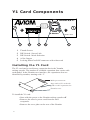
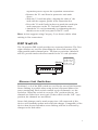
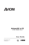
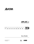
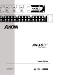
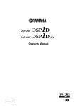
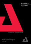
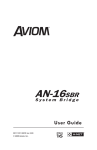
AVIOM16/ O -Y1
A-NET OUTPUT CARD FOR
YAMAHA DIGITAL MIXERS
������������
����
�
�
�
�
�
�
������ ����
�
�
�
Dn/Up - Aviom
Up/Dn - 16 ch
Up/Up - 8 ch
Dn/Dn - Test
��
����� ���
���� �� ���
U SER G UIDE
!
Warning
Failure to observe the following warnings may
lead to risk of serious injury from fire or electric
shock.
Before installing the card, you must refer to the owner’s manual of the
host device or to the Yamaha web site to verify that your host device
supports this card, and to verify the number of cards that can be
installed in combination with other Yamaha or third-party cards.
• Do not attempt to disassemble or modify the card. Do
not apply excessive force to board connectors or other
board components. (Mishandling the board may lead to
shock, fire hazard, or equipment failure.)
• You must turn off the power of your device before you
begin installing the AVIOM16/o-Y1 card.
• Be sure to disconnect the power cable from the main
unit before installing this card (to eliminate shock
hazard).
!
Caution
Failure to observe the following precautions may
lead to personal injury, or may result in damage to
equipment or other property.
• Do not touch the board’s metallic leads (pins) when
handling the card. (Pins are sharp and may cause hand
cuts.)
• The card is electrostatic-sensitive. Before handling the
card, you should briefly touch the main unit’s metal
casing with your bare hand so as to drain off any static
charge from your body.
Information in this document is subject to change. All rights reserved.
Copyright ©2004 Aviom, Inc.
Printed in USA
Document Rev. 1.01
1
WARNING!
!
NO USER SERVICEABLE PARTS INSIDE
REFER SERVICING TO QUALIFIED SERVICE PERSONNEL
ONLY
• To reduce the risk of fire or electrical shock, do not
expose this product to rain or other types of moisture.
• Operating Temperature: 10˚C to 40˚C (50˚F to 105˚F)
CAUTION:
• Using any audio system at high volume levels
can cause permanent damage to your hearing.
• Set your system volume as low as possible.
• Avoid prolonged exposure to excessive sound
pressure levels.
IMPORTANT:
This equipment has been tested and found to comply with the limits for
a Class B digital device, pursuant to part 15 of the FCC Rules. These
limits are designed to provide reasonable protection against harmful
interference in a residential installation. This equipment generates, uses
and can radiate radio frequency energy and, if not installed and used in
accordance with the instructions, may cause harmful interference to radio
communications. However, there is no guarantee that interference will not
occur in a particular installation. If this equipment does cause harmful
interference to radio or television reception, which can be determined by
turning the equipment off and on, the user is encouraged to try to correct
the interference by one or more of the following measures:
• Reorient or relocate the receiving antenna.
• Increase the separation between the equipment and
receiver.
• Connect the equipment into an outlet on a circuit different
from that to which the receiver is connected.
• Consult the dealer or an experienced radio/TV technician
for help.
Changes or modifications to the product not expressly approved by Aviom,
Inc. could void the user’s FCC authority to operate the equipment.
2
Warranty Information
Please record the following information for future reference:
Your Authorized Aviom Dealer:
Name:
_____________________________
Address: _____________________________
_____________________________
Phone:
_____________________________
Serial Number of Your Aviom Product: ___________________
Date of Purchase: ________________
Your Authorized Aviom Dealer is your primary source for service and
support. The information recorded above will be helpful in communicating with your Authorized Aviom Dealer should you need to contact
Aviom Customer Service. If you have any questions concerning the use
of this unit, please contact your Authorized Aviom Dealer first. For additional technical support, or to find the name of the nearest Authorized
Aviom Repair Station, check the Aviom web site at www.aviom.com.
To fulfill warranty requirements, your Aviom product should be
serviced only at an authorized Aviom service center. The Aviom serial
number label must appear on the outside of the unit, or the Aviom
warranty is void.
This manual and its contents are copyrighted by Aviom, Inc. All rights
are reserved by Aviom, Inc. This document may not, in whole or in
part, be copied, photocopied, reproduced, translated, or reduced to any
electronic medium or machine-readable form without prior written
consent from Aviom, Inc.
The software and/or firmware contained within Aviom products is
copyrighted and all rights are reserved by Aviom, Inc.
Although every effort has been made to ensure the accuracy of the text
and illustrations in this manual, no guarantee is made or implied as to
the accuracy of the information contained within.
Personal Monitor Mixing System is a trademark of Aviom, Inc.
A-Net is a trademark of Aviom, Inc.
©2004 Aviom, Inc.
3
Aviom, Inc. Limited Warranty
Aviom, Inc. warrants this product against defects in materials and workmanship
for a period of one year from the date of the original retail purchase.
This warranty does not apply if the equipment has been damaged due to misuse,
abuse, accident, or problems with electrical power. The warranty also does
not apply if the product has been modified in any way, or if the product serial
number has been damaged, modified, or removed.
If a defect is discovered, first write or call Aviom, Inc. to obtain a Return
Authorization number. No service will be performed on any product returned
without prior authorization. Aviom, Inc. will, at its option, repair or replace the
product at no charge to you. The product must be returned during the warranty
period, with transportation charges prepaid to Aviom, Inc., 1157 Phoenixville
Pike, Suite 201, West Chester, PA 19380, USA. You must use the product’s
original packing materials for shipment. Shipments should be insured for the
value of the product. Include your name, address, phone number, description of
the problem, and copy of the original bill of sale with the shipment. The Return
Authorization number should be written on the outside of the box.
THIS LIMITED WARRANTY GIVES YOU SPECIFIC LEGAL RIGHTS.
YOU MAY HAVE OTHER RIGHTS, WHICH VARY FROM STATE TO
STATE (OR JURISDICTION TO JURISDICTION). AVIOM’S RESPONSIBILITY FOR MALFUNCTIONS AND DEFECTS IN HARDWARE IS
LIMITED TO REPAIR AND REPLACEMENT AS SET FORTH IN THIS
LIMITED WARRANTY STATEMENT. ALL EXPRESS AND IMPLIED
WARRANTIES FOR THE PRODUCT, INCLUDING BUT NOT LIMITED TO
ANY IMPLIED WARRANTIES OF MERCHANTABILITY AND FITNESS
FOR A PARTICULAR PURPOSE, ARE LIMITED IN DURATION TO
THE WARRANTY PERIOD SET FORTH ABOVE. NO WARRANTIES,
WHETHER EXPRESS OR IMPLIED, WILL APPLY AFTER SUCH PERIOD.
AVIOM, INC. DOES NOT ACCEPT LIABILITY BEYOND THE REMEDIES
SET FORTH IN THIS LIMITED WARRANTY DOCUMENT. AVIOM, INC.’S
LIABILITY IS LIMITED TO THE REPAIR OR REPLACEMENT, AT OUR
OPTION, OF ANY DEFECTIVE PRODUCT, AND SHALL IN NO EVENT
INCLUDE INCIDENTAL OR CONSEQUENTIAL DAMAGES OF ANY
KIND.
SOME STATES DO NOT ALLOW EXCLUSIONS OR LIMITATION OF
IMPLIED WARRANTIES OR LIABILITY FOR INCIDENTAL OR CONSEQUENTIAL DAMAGES, SO THE ABOVE LIMITATIONS MAY NOT
APPLY TO YOU.
Aviom and the Aviom logo are trademarks of Aviom, Inc.
4
Welcome
Thank you for purchasing the AVIOM16/o-Y1 A-Net Output Card
for Yamaha Digital Mixers. This User Guide is designed to familiarize you with your new product and to have you up and running in no
time.
Features
The AVIOM16/o-Y1 A-Net Output Card (or “Y1” for short) provides a
host of professional features designed to make using A-Net monitoring
products flexible and easy to configure in a variety of professional
audio situations.
Y1 A-Net Output Card Features:
• Sixteen audio channels
• One A-Net output, EtherCon RJ45 connector
• Channel link switches for stereo channel pairing
• Compatible with all Yamaha digital mixing consoles
that use the Yamaha mini-YGDAI digital format for
expansion cards
• Compatibility modes for 8-channel and 16-channel
operation (The PM1D is an 8-channel device.)
• Test mode
The Y1 card is designed to be electrically and mechanically compatible with any Yamaha mixing board product that supports the
mini-YGDAI card hardware specification. Consult the documentation
provided with your Yamaha product for additional information.
The EtherCon Connector
The Neutrik EtherCon connector is a dual RJ45 type connector. It can
receive a standard Category 5e cable or a cable fitted with the special
heavy-duty EtherCon connector.
When using a standard Cat-5e cable, plug the cable into the center of
the jack; release the cable by pressing on the small plastic tab built into
the cable connector.
The locking EtherCon connector is similar to an XLR cable, the
kind commonly used on microphones. Insert the EtherCon equipped
cable into the jack until it clicks and locks in place. To remove the
cable, press on the metal release tab at the top of the panel-mounted
EtherCon jack and pull the connector outward.
5
Y1 Card Components
������������
����
�
�
�
�
�
�
�
�
�
Dn/Up - Aviom
Up/Dn - 16 ch
Up/Up - 8 ch
Dn/Dn - Test
��
������ ����
����� ���
���� �� ���
1
1
2
3
4
5
2
3
4
5
Thumb Screws
DIP Switch - Stereo Link
DIP Switch - Mode Selection
A-Net Output
Locking EtherCon RJ45 connector with release tab
Installing the Y1 Card
The Y1 card can be used in any expansion slot in the Yamaha
mixing console. The number of available expansion slots varies with
each model. In the Yamaha user interface, the expansions slots are
identified by number, starting with “1”.
Multi-pin connector
Align sides of Y1 card with
guides in the expansion slot
Thumb screws
To install the Y1 card:
• Start with the power to the Yamaha mixing console off.
• Remove the mixer’s power cord from the wall
receptacle.
• Remove the cover plate on the rear of the Yamaha
6
expansion port to expose the expansion connections.
• Remove the Y1 card from its protective anti-static
sleeve.
• Slide the Y1 card into place, aligning the sides of the
card with the support guides in the expansion slot.
• Press the Y1 card firmly in place to attach the multi-pin
card connectors on the Y1 card and Yamaha mixer.
• Attach the Y1 card permanently by tightening the two
thumb screws on the rear panel of the Y1 card.
NOTE: Aviom suggests using Category 5e (or better) cables when
making A-Net connections.
DIP Switch
The 10-position DIP switch provides two separate functions. The first
eight switches are used for controlling the stereo link status of the
eight possible audio channel pairs. The last two switches (labeled 9
and 10) provide mode selection control for the Y1 card operation.
����
����
�
�
�
�
�
�
�
�
�
�
�
�
�
������ ����
������ ����
�
�
�
�
�
����
Dn/Up - Aviom
Up/Dn - 16 ch
Up/Up - 8 ch
Dn/Dn - Test
��
��
����� ���
Stereo Link Switches
Positions 1 to 8 of the DIP switch are used for the stereo link function.
Stereo linking is possible when using Aviom’s Personal Mixers for
stereo monitoring. Each switch controls a pair of channels; see the
list below. When the switch is set to the “On” position (down), the
channels are linked as a stereo pair. If the switch is in the “Off “ (up)
position, the channels are not linked.
Stereo link changes can be made at any time. All connected A-Net
devices will instantly update and reflect the change. Compatible A-Net
devices that do not respond to stereo linking will not be affected by
changes to the link status.
7
The DIP switch 1 to 8 definitions are as follows:
• Switch 1 - controls channels 1 and 2
• Switch 2 - controls channels 3 and 4
• Switch 3 - controls channels 5 and 6
• Switch 4 - controls channels 7 and 8
• Switch 5 - controls channels 9 and 10
• Switch 6 - controls channels 11 and 12
• Switch 7 - controls channels 13 and 14
• Switch 8 - controls channels 15 and 16
����
�
�
�
�
�
�
�
�
�
��
������ ����
The example above shows a configuration where channel pairs 3-4,
13-14, and 15-16 are set for stereo operation.
Mode Select Switches
Positions 9 and 10 of the DIP switch are used for card mode selection.
There are four possible switch combinations; three operational modes
and one test mode are provided.
The Y1 card is scanned during the Yamaha console boot-up procedure
only. It is therefore important to remember that mode changes should
be made only while the console is off. If it is necessary to alter the Y1
card operational mode after the console has been booted, a console
restart will be required in order for the mode change to be recognized.
■ Switch 9 ON and Switch 10 OFF – Aviom Mode
����
�
�
�
�
�
�
�
�
�
��
������ ����
The Yamaha console software recognizes the Aviom Y1
A-Net card ID’s and will display “Aviom” in all text fields
related to the expansion card.
8
NOTE: Not all Yamaha mixers are compatible with
Aviom Mode. Software and firmware updates to the
Yamaha console may be required. Consult Yamaha
Customer Service and/or your mixer’s documentation for additional details.
■ Switch 9 OFF and Switch 10 ON – MY16-AT Mode
����
�
�
�
�
�
�
�
�
�
��
������ ����
Yamaha 16-channel capability mode.
The Yamaha console recognizes the Y1 card as a generic
16-channel expansion card. Names in text fields will
display with a generic name (such as “ADAT 16”),
depending on the model number and software version of
the Yamaha console.
!
In most cases, this mode should be selected as the default
setting for the Aviom Y1 card.
■ Switch 9 OFF and Switch 10 OFF – MY8-AT Mode
����
�
�
�
�
�
�
�
�
�
��
������ ����
Yamaha 8-channel capability mode.
Certain Yamaha consoles can support only 8-channel
9
input or output expansion cards. Use this mode only with
products designated as 8-channel devices. Consult the
Yamaha mixing console’s documentation for additional
information about 8-channel compatibility. (The PM1D is
an 8-channel device.)
■ Switch 9 ON and Switch 10 ON – Test Mode
����
�
�
�
�
�
�
�
�
�
��
������ ����
In Test Mode, channels 1 through 4 output a 1kHz, 48k
sine wave. This mode can be used to troubleshoot an
audio system. Make sure to set the Yamaha console’s
internal sample rate to 48k when using Test Mode.
When troubleshooting using the Y1 card Test Mode, if
the 1kHz test tones are heard in channels 1 through 4 of a
connected A-Net device, this indicates that the Y1 card is
operating properly. Check the channel routing settings in
the Yamaha console user interface to determine that audio
is being routed properly.
!
WARNING: Before switching the Y1 card to Test
Mode, lower the volume on any connected A-Net
devices to avoid sudden volume changes and/or
possible hearing damage.
To exit the Test Mode, a console restart is required. Power
off the Yamaha mixing console. Reset the Y1 card DIP
switches to the desired operational mode position, and
then reboot the Yamaha console.
10
Aviom Warranty Registration
Please take a moment to fill in this warranty registration form. Return it to
Aviom via mail or fax. All information will be kept confidential.
Model Number ................................
Serial Number ................................
Model Number ................................
Serial Number ................................
Model Number ................................
Serial Number ................................
Model Number ................................
Serial Number ................................
Date Purchased ...............................
Dealer Name ..........................................................................................................
Dealer Location ......................................................................................................
......................................................................................................
Your Name ..........................................................................................
Address ................................................................................................
Address ...............................................................................................
City ......................................................................................................
State/Province ..................................................
Zip/Postal Code ...............................................
Country .............................................................
Email Address .............................................................................................
Fax this form to Aviom at +1 610-738-9950
12
Aviom, Inc.
1157 Phoenixville Pike
Suite 201
West Chester, PA 19380
www.aviom.com
Part Number 9310 1008 0001