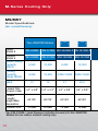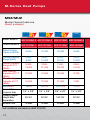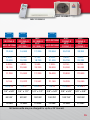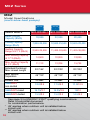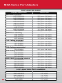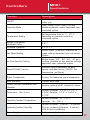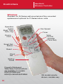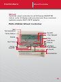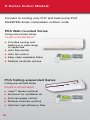
1
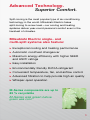
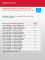
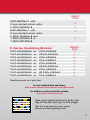
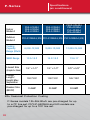
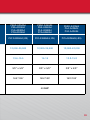
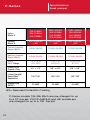
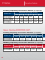
M-SERIES & P-SERIES
Pocket Reference Guide
CounterPRO
Your #1 Support Team
mitsubishipro.com
© 2012 Mitsubishi Electric & Electronics USA, Inc.
I
Form No. MQRO 01-12 Reprint
Pre-visit Checklist
3
Verify appointment
3
Call 30 minutes before you arrive
3
Verify equipment in stock at distributor
3
Credit application/financing options
3
Local rebate information
3
Bring this booklet along so you have
product information and the contact
phone numbers below handy
Inside Sales: 866-323-4822
Service: 877-391-5550
M-Series Applications: 800-433-4822 (press 3)
Parts: 678-376-2940
www.mitsubishipro.com
Advanced Technology. Superior Comfort.
Split-zoning is the most popular type of air-conditioning
technology in the world. Mitsubishi Electric takes
split-zoning to a new level—our cooling and heating
systems deliver year-round personal comfort even in the
harshest of climates.
Mitsubishi Electric single- and
multi-split systems also feature:
▶▶
Exceptional cooling and heating performance
▶▶
Automatic cool/heat changeover
▶▶
aximum energy efficiency with higher SEER
M
and HSPF ratings
▶▶
Easy installation
▶▶
Environmentally friendly R410A refrigerant
▶▶
Convenient temperature, fan, and airflow control
▶▶
Advanced filtration to help provide high air quality
▶▶
Whisper-quiet operation
M-Series components are up to
83 % recyclable
M-Series was green before
green was cool.
1
ENERGY STAR®
Mitsubishi Electric systems are now
more environmentally friendly than ever!
Use them to earn any available state, municipal,
and utility rebates.
M-Series Qualifying Models*
MUY-GE09NA w/ MSY-GE09NA-8
MUY-GE12NA w/ MSY-GE12NA-8
MUY-GE15NA-1 w/ MSY-GE15NA-8
MUY-GE24NA w/ MSY-GE24NA
MUZ-GE09NA w/ MSZ-GE09NA-8
MUZ-GE12NA w/ MSZ-GE12NA-8
MUZ-GE15NA-1 w/ MSZ-GE15NA-8
MUZ-GE24NA w/ MSZ-GE24NA
MUZ-FE09NA-1 w/ MSZ-FE09NA-8
MUZ-FE12NA1 w/ MSZ-FE12NA-8
MUZ-FE18NA w/ MSZ-FE18NA
SUZ-KA09NA w/ SEZ-KD09NA4
SUZ-KA12NA w/ SEZ-KD12NA4
SUZ-KA15NA w/ SEZ-KD15NA4
SUZ-KA18NA w/ SEZ-KD18NA4
SUZ-KA09NA w/ SLZ-KA09NA
SUZ-KA12NA w/ SLZ-KA12NA
*Qualifying model as of print time
2
Energy
Star
3
3
3
3
3
3
3
3
3
3
3
3
3
3
3
3
3
Energy
Star
MXZ-2B20NA-1 with
2 non-ducted indoor units
2 MSZ-GE09NA-8
MXZ-3B24NA-1 with
3 non-ducted indoor units
2 MSZ-GE06NA-8 and
1 MSZ-GE09NA-8 or
1 MSZ-GE12NA-8
P-Series Qualifying Models*
PUZ-HA30NHA4
PUZ-HA30NHA4
PUZ-HA30NHA4
PUZ-HA30NHA4
PUZ-HA36NHA4
PUZ-HA36NHA4
PUZ-HA36NHA4
PUZ-HA36NHA4
PUZ-HA36NHA4
w/
w/
w/
w/
w/
w/
w/
w/
w/
PCA-A30KA4
PEAD-A30AA4
PKA-A30KA4
PLA-A30BA4
PCA-A36KA4
PEAD-A36AA4
PKA-A36KA4
(2) PEA-A18AA4
PLA-A36BA4
3
3
3
3
Energy
Star
3
3
3
3
3
3
3
3
3
*Qualifying model as of print time
For tax credit details and forms,
visit www.mitsubishicomfort.com/taxcredit
For details on state and utility rebates,
visit www.dsireusa.org
Get the free mobile app at
Use your smart phone to scan the
tag to the left and go to the page.
Get the free app for your smart
phone at http://gettag.mobi
3
Features & Benefits
M-Series Systems
How to Read a Model Number
M X Z - 2 B 20 N A - 1
FAMILY
M = Mini-split
S = Mini-split
TYPE
S = Wall-mounted indoor unit
E = Horizontal-ducted indoor unit
U = Single system outdoor unit
X = Multi-system outdoor unit
F = Floor-mounted unit
L = Ceiling recessed indoor unit
COOLING ONLY / HEAT PUMP
Nothing = Cooling only (non-INVERTER)
Y = Cooling only (INVERTER-driven)
Z = Heat pump (INVERTER-driven)
NUMBER OF ZONES
MODEL VERSION
WIRING METHOD
A = A Control
COMPRESSOR
VOLTAGE
W = 115V Compressor
N = 230V Compressor
CAPACITY (nominal)
In Btu/h (x 1,000)
SYSTEM
GENERATION
2 = Max. number of zones
M-Series (9,000 - 48,000 Btu/h)
1. For residential and light commercial buildings
(including conference rooms and storage areas)
2. User-friendly cooling and heating solutions for
single-room and multi-room applications
3. H2i (hyper-heating INVERTER) outdoor units
can provide high heating at lower ambient
temperatures
4. 19 ENERGY STAR® models
4
How to Read a Model Number
pka
a 24 Ka 4 bs
FAMILY
P = Professional
TYPE
K = Wall-mounted indoor unit
C = Ceiling-suspended indoor unit
L = Ceiling-recessed indoor unit
E = Horizontal-ducted indoor unit
U = Single system outdoor unit
COOLING ONLY / HEAT PUMP
Y = Cooling only (INVERTER-driven)
Z = Heat pump (INVERTER-driven)
A = Both heating and cooling
BS = Seacoast protection
pkg. for outdoor unit
Model Version
SYSTEM Controls
generation
CAPACITY (nominal)
In Btu/h (x 1,000)
GENERATION
A = Generation A
HA = Hyper-heating INVERTER unit
P-Series (12,000 - 42,000 Btu/h)
1. For commercial, industrial, institutional, and
large residential buildings - ideal in areas
requiring year-round, low ambient cooling such
as computer, elevator and equipment rooms
2. H2i (Hyper Heating Inverter) outdoor units
can provide high heating at lower ambient
temperatures
3. Long lineset lengths
4. Outside air intake on PLA, PCA
and PEA/D models
5
M-Series Models
Our standard line is now greener than ever!
GE Models
Eight ENERGY STAR®
models
▶▶ “Smart Set" programming
(9,000 - 22,500 Btu/h)
button with SETBACK
down to 50º F in heating
(9,000 - 18,000 only)
▶▶ Washable 10-year catechin filter and anti-allergy
enzyme filter
▶▶ Cooling-only and heat pump models
▶▶ Five fan speeds plus AUTO
See page 12-15 for more information.
▶▶ As quiet as 19 dB(A)
▶▶
D Models
(30,700 - 34,600 Btu/h)
Wide vane mode for precise directional airflow (also
available on MSY/Z-GE24NA & MSZ-FE18NA)
▶▶ Powerful mode for quick 15 minute heating/cooling
boost (also available on MSY/Z-GE24NA
and MSZ-FE18NA)
▶▶ Cooling-only and heat pump models
▶▶
With the WIDE VANE or SWING mode,
available on the MSY(Z)-GE24/
D30/36NA and MSZ-FE18NA, there
is an option for seven horizontal
airflow directions that provide 150°
of airflow for greater conditioned air
circulation.
150°
6
High-efficiency, Hyper-Heating systems
FE Models
Three ENERGY STAR®
models
▶▶ i-see™ sensor
(9,000 - 18,000 Btu/h)
automatically adjusts
comfort conditioning by sensing temperature variations
in the room and adjusting vane direction (MSZ-FE09
and MSZ-FE12 models only)
▶▶ 100% heating capacity at 5º F on MSZ-FE09NA and
MSZ-FE18NA; 92% capacity at 5º F
on MSZ-FE12NA
▶▶ Standard filters plus platinum catalyst deodorizing filter
▶▶ Four fan speeds plus AUTO
See page 14 for more information.
▶▶ As quiet as 22 dB(A)
▶▶
MFZ Models
Ideal for low-wall mounted
applications
▶▶ Bi-directional airflow (top
and bottom discharge)
▶▶ “Smart Set" programming
(9,000 - 18,000 Btu/h)
button with SETBACK down
to 50º F in heating
▶▶ Washable, 10-year catechin filter and anti-allergy
enzyme filter
▶▶ For use with MXZ multi-zone outdoor units only
▶▶
7
M-Series Models
SEZ Models
(8,100 – 17,200 Btu/h)
Small compact design (7-7/8" height)
Adjustable static pressure
▶▶ Built-in condensate lift mechanism (22-1/2" lift)
▶▶ Rear return or bottom return (with optional accessory)
▶▶ Low operating sound pressure levels; as low as 23
dB(A)
▶▶ All four models ENERGY STAR® rated
▶▶
▶▶
See page 16-17 for more information.
SLZ Models
(8,400 – 15,000 Btu/h)
Fits in 2x2 suspended ceiling grid
4-way airflow
▶▶ Built-in condensate lift mechanism (19-11/16" lift)
▶▶ Catechin deodorizing filter
▶▶ Two models ENERGY STAR® rated
▶▶ Outside air intake
▶▶
▶▶
8
select
systems
M-Series Models
Multi-Zone Heat Lineup
MXZ Multi-Zone
Heat Pumps
In door U n i ts :
2:1, 3:1, 4:1, and 8:1 Zoned Solutions
(20,000-48,000 Btu/h)
hree combinations qualify
T
for ENERGY STAR®
▶▶ Precise, individual room
comfort control
▶▶ Multiple indoor air handler
options (ductless and ducted)
▶▶ Minimum of two indoor units
must be installed
▶▶
MSZ-FE09 -18NA
MSZ-GE06-24NA
SLZ-KA09-15NA
PLA-A12-24BA4
MF Z- K A 09-18NA
(for use with MXZ-B only)
select
systems
Outd o o r Uni ts:
M XZ-2 B2 0NA -1 (2:1)
M XZ-3 B2 4NA -1 (2:1, 3:1)
M XZ-3 B3 0NA -1 (2:1, 3:1)
M XZ-4 B3 6NA -1 (2:1, 3:1, 4: 1)
M XZ-8 B4 8NA (2:1 - 8:1)
See pages 18-19 for more information.
S EZ-K D09-18NA 4
PEA D-A 24AA 4
9
M-Series Models
Di am ond C o m f o r t M X Z
MXZ-8B48NA
Outdoor Unit
SEZ Horizontal-DUCTED
INDOOR UNITS
SEZ-KD09-18NA4 Models
10
MFZ FLOOR-MOUNTED
Indoor units
MFZ-KA09-18NA Models
(for use with MXZ-B units only)
M ulti-zone S ys t e m s
MSZ WALL-MOUNTED
INDOOR UNITS
MSZ-FE09-18NA
MSZ-GE06-24NA
PEAD Horizontal-DUCTED
INDOOR UNITS
PEAD-A24AA4 Models
SLZ CEILING-RECESSED
Indoor units
SLZ-KA09-15NA
PLA-A12-24BA4 Models
11
M-Series Cooling Only
MS/MSY
Model Specifications
(air conditioners)
*Non-INVERTER Models
Indoor
Model #
Outdoor
Model #
*MS-A09WA *MS-A12WA MSY-GE09NA-8 MSY-GE12NA-8
*MU-A09WA *MU-A12WA MUY-GE09NA MUY-GE12NA
Rated Cooling
Capacity
(Btu/h)
9,500
12,000
Cooling
Capacity
Range (Btu/h)
9,500
12,000
13
13
SEER
Lineset Size
(Liquid x Gas)
1/4" x 3/8" 1/4" x 1/2"
9,000
12,000
3,800-12,200 3,800-13,600
21
20.5
1/4" x 3/8"
1/4" x 3/8"
Lineset
Length/
Height Max.
Separation
65'/35'
65'/35'
65'/40'
65'/40'
Breaker Size
15 AMP
20 AMP
15 AMP
15 AMP
*Use ICM-326HM-1 Head Pressure Controller Accessory for Non-INVERTER
Models (for low outdoor ambient cooling only).
12
MUY-GE15NA-1
MSY-GE15NA-8
MSY-GE15NA-8 MSY-GE18NA-8 MSY-GE24NA MSY-D30NA-8 MSY-D36NA-8
MUY-GE15NA-1 MUY-GE18NA-1 MUY-GE24NA MUY-D30NA-1 MUY-D36NA-1
14,000
17,200
22,500
30,700
34,600
3,100-18,200 3,700-18,700 8,200-31,400 9,800-30,700 9,800-34,600
21
19.2
19
16
15.1
1/4" x 1/2"
1/4" x 1/2"
3/8" x 5/8"
3/8" x 5/8"
3/8" x 5/8"
65'/40'
100'/50'
100'/50'
100'/50'
100'/50'
15 AMP
15 AMP
20 AMP
25 AMP
25 AMP
M-Series units are pre-charged for up to a 25' line set.
13
M-Series Heat Pumps
MSZ/MUZ
Model Specifications
(heat pumps)
Indoor Model #
MSZ-FE09NA-8 MSZ-FE12NA-8 MSZ-FE18NA MSZ-GE09NA-8
Outdoor Model # MUZ-FE09NA-1 MUZ-FE12NA1 MUZ-FE18NA
MUZ-GE09NA
Rated Cooling
Capacity (Btu/h)
9,000
12,000
18,000
9,000
Cooling Capacity
Range (Btu/h)
2,8009,000
2,80012,000
8,20025,200
3,80012,200
3,00018,000
3,00021,000
7,50029,700
4,50014,100
12,500
13,600
19,300
8,700
10,900
12,500
21,600
7,061
26/10
23/10.5
20.2/10.3
21/10
1/4" x 3/8"
1/4" x 3/8"
3/8" x 5/8"
1/4" x 3/8"
65'/40'
65'/40'
100’/50’
65'/40'
15 AMP
15 AMP
20 AMP
15 AMP
Heating Capacity
Range at 47°F
(Btu/h)
Max. Heating
Capacity at 17°F
(Btu/h)
Max. Heating
Capacity at 5°F
(Btu/h)
SEER/HSPF
Lineset Size
(Liquid x Gas)
Lineset Length/
Height Max.
Separation
Breaker Size
Test conditions are based on AHRI 210/240.
14
MUZ-FE09NA-1
MSZ-FE09NA-8
MSZGE12NA-8
MUZ-GE12NA
MSZGE15NA-8
MUZGE15NA-1
MSZMSZ-GE24NA
GE18NA-8
MUZMUZ-GE24NA
GE18NA-1
MSZD30NA-8
MUZD30NA-1
MSZD36NA-8
MUZD36NA-1
12,000
14,000
17,200
22,500
30,700
33,200
3,80013,600
3,10018,200
3,70018,700
8,20031,400
9,80030,700
9,80033,200
5,50018,100
4,80020,900
3,50025,200
7,50036,900
8,70034,000
8,70036,000
11,200
15,900
17,200
24,600
20,800
22,800
9,194
13,022
13,562
21,160
16,305
19,090
20.5/10
21/10
19.2/10
19/10
14.5/8.2
14.5/8.2
1/4" x 3/8"
1/4" x 1/2"
1/4" x 1/2"
3/8" x 5/8"
3/8" x 5/8"
3/8" x 5/8"
65'/40'
65'/40'
100'/50'
100'/50'
100'/50'
100'/50'
15 AMP
15 AMP
15 AMP
20 AMP
25 AMP
25 AMP
M-Series units are pre-charged for up to a 25' line set.
15
SEZ/SLZ Models Specifications
(heat pumps)
SEZ-KD15NA4
SUZ-KA15NA
Indoor Model #
SEZ-KD09NA4
SEZ-KD12NA4
SEZ-KD15NA4
Outdoor Model #
SUZ-KA09NA
SUZ-KA12NA
SUZ-KA15NA
8,100
11,500
14,100
Cooling Capacity
Range (Btu/h)
3,800-10,900
3,800-13,300
3,800-17,000
Heating Capacity
Range at 47ºF (Btu/h)
4,800-14,100
4,800-16,400
4,800-21,100
Max Heating Capacity
at 17ºF (Btu/h)
6,700
9,000
11,900
SEER/HSPF
15/10
16/10
15.5/10
1/4" x 3/8"
1/4" x 3/8"
1/4" x 1/2"
Lineset Length/Height
Max. Separation
65’/40’
65’/40’
65’/40’
Breaker Size (MOCP)
15 AMP
15 AMP
15 AMP
Rated Cooling Capacity
(Btu/h)
Lineset Size
(Liquid x Gas)
16
All Controllers
Ordered separately
SLZ-KA15NA
MHK1
TM
SEZ-KD18NA4
SLZ-KA09NA
SLZ-KA12NA
SLZ-KA15NA
SUZ-KA18NA
SUZ-KA09NA
SUZ-KA12NA
SUZ-KA15NA
17,200
8,400
11,100
15,000
3,800-19,000
3,100-10,900
3,400-13,300
3,800-17,700
4,800-24,900
3,100-14,100
3,100-17,100
3,100-22,200
13,100
6,200
8,300
12,000
17.5/10
15/9.6
15.4/9.6
16/9.6
1/4" x 1/2"
1/4" x 3/8"
1/4" x 3/8"
1/4" x 1/2"
100’/50’
65’/40’
65’/40’
65’/40’
15 AMP
15 AMP
15 AMP
15 AMP
17
MXZ Series
MXZ
Model Specifications
(multi-zone heat pumps)
Outdoor Model #
MXZ-2B20NA-1 MXZ-3B24NA-1 MXZ-3B30NA-1
Rated Cooling
Capacity (Btu/h)
18,000
22,000
28,400
Cooling Capacity
Range (Btu/h)
7,800-20,000
12,600-25,500
12,600-28,400
Heating Capacity
Range at 47°F (Btu/h)
8,500-25,500
11,400-30,600
11,400-36,000
Max. Heating Capacity
at 17°F (Btu/h)
14,500
18,800
18,800
Max. Heating Capacity
at 5°F (Btu/h)
11,113
13,336
15,704
Individual/Combined
Max. Lineset Length
82'/164'
82'/230'
82'/230'
Max. Vertical
Separation
49'*/33'
49'*/33'
49'*/33'
20 AMP
20 AMP
20 AMP
18.0/8.9
17.5/9.3
17.5/10.5
SEER/HSPF mixed
16.75/8.7
16.25/8.9
16/10
SEER/HSPF ducted
15.5/8.5
15.0/8.5
14.5/9.5
Breaker Size
SEER/HSPF
non-ducted
See page 3 for ENERGY STAR qualifying combinations. Refer to submittal document
for combination performance.
* 49' applies when outdoor unit is installed below
indoor unit.
** 66' applies when outdoor unit is installed below
indoor unit.
18
®
MXZ-4B36NA-1 MXZ-8B48NA
35,400
48,000
12,600-36,400 12,000-54,000
11,400-43,000 12,000-60,000
24,600
36,600
18,671
32,400
82'/230'
230'/377'
49'*/33’
66'**/98'
25 AMP
50 AMP
18.0/9.3
15.0/8.7
16.5/9.2
14.8/8.8
15.0/9.0
14.7/8.9
MXZ-8B48NA
BRANCH BOX FOR INDOOR
UNIT CONNECTIONS
Each MXZ-8B48NA requires
at least one branch box with
a maximum of two. Two
sizes are available: 3-branch
(PAC-AKA31BC) and 5-branch
(PAC-AKA51BC, shown above).
See page 20 for indoor
unit Connection
Capabilities
See section 5 of installation manual for full details
on MXZ-8B48NA refrigeration piping lengths.
19
MXZ-Series Port Adapters
Port AdaptEr Guide
Available Indoor Units
Line set size
MSZ Wall-mounted
MSZ-GE06NA-8
3/8" gas x 1/4" liquid
MSZ-GE09NA-8
3/8" gas x 1/4" liquid
MSZ-FE09NA-8
3/8" gas x 1/4" liquid
MSZ-GE12NA-8
3/8" gas x 1/4" liquid
MSZ-FE12NA-8
3/8" gas x 1/4" liquid
MSZ-GE15NA-8
1/2" gas x 1/4" liquid
MSZ-FE18NA
5/8" gas x 3/8" liquid
MSZ-GE18NA-8
1/2" gas x 1/4" liquid
MSZ-GE24NA
5/8" gas x 3/8" liquid
MFZ Floor-standing
MFZ-KA09NA
3/8" gas x 1/4" liquid
MFZ-KA12NA
3/8" gas x 1/4" liquid
MFZ-KA18NA
1/2" gas x 1/4" liquid
PLA Ceiling-recessed
PLA-A12BA4
1/2" gas x 1/4" liquid
PLA-A18BA4
1/2" gas x 1/4" liquid
PLA-A24BA4
5/8" gas x 3/8" liquid
PCA Ceiling-suspended
PCA-A24KA4
5/8" gas x 3/8" liquid
SLZ Ceiling-recessed
SLZ-KA09NA
3/8" gas x 1/4" liquid
SLZ-KA12NA
3/8" gas x 1/4" liquid
SLZ-KA15NA
1/2" gas x 1/4" liquid
SEZ/PEAD Horizontal-ducted
SEZ-KD09NA4
3/8" gas x 1/4" liquid
SEZ-KD12NA4
3/8" gas x 1/4" liquid
SEZ-KD15NA4
1/2" gas x 1/4" liquid
SEZ-KD18NA4
1/2" gas x 1/4" liquid
PEAD-A24AA4
5/8" gas x 3/8" liquid
Port Adapters Part Numbers
20
MAC-A454JP-E
3/8" x 1/2"
MAC-A455JP-E
1/2" x 3/8"
MAC-A456JP-E
1/2" x 5/8"
PAC-SG76RJ-E
3/8" x 5/8"
PAC-493PI
1/4" x 3/8"
MXZ-2B20NA-1
MXZ-3B30NA-1
Port A = 3/8" gas x 1/4" liquid
Port A = 1/2" gas x 1/4" liquid
Port B = 3/8" gas x 1/4" liquid
Port B = 3/8" gas x 1/4" liquid
Port C = 3/8" gas x 1/4" liquid
MXZ-3B24NA-1
Port A = 1/2" gas x 1/4" liquid
MXZ-4B36NA-1
Port B = 3/8" gas x 1/4" liquid
Port A = 1/2" gas x 1/4" liquid
Port C = 3/8" gas x 1/4" liquid
Port B = 3/8" gas x 1/4" liquid
Port C = 3/8" gas x 1/4" liquid
Port D = 3/8" gas x 1/4" liquid
MXZ-8B48NA
Branch Box
Branch Box
PAC-AKA31BC
PAC-AKA51BC
PORT A = 3/8" gas x 1/4" liquid
PORT A = 3/8" gas x 1/4" liquid
PORT B = 3/8" gas x 1/4" liquid
PORT B = 3/8" gas x 1/4" liquid
PORT C = 3/8" gas x 1/4" liquid
PORT C = 3/8" gas x 1/4" liquid
PORT D = 3/8" gas x 1/4" liquid
PORT E = 1/2" gas x 1/4" liquid
Notes for application:
**Check the lineset sizes for your indoor selected models.
**Select the branch box or boxes needed for your application.
**Compare indoor unit lineset sizes to branch box or outdoor
unit port sizes.
**Connect 15K + indoor units to the larger 1/2" port on the
PAC-AKA51BC branch box or outdoor unit.
**Adapt lineset size with appropriate port adapter from above list.
**When using the PLA-A24BA4, PEAD-A24AA4, PCA-A24KA4 MSZ-FE18NA
or MSZ-GE24NA two port adapters will be needed
1-MAC-A456JP-E (1/2" x 5/8") or 1-PAC-SG76RJ-E (3/8" x 5/8") and
1-PAC493PI (1/4" x 3/8").
21
M-Series Correction Factors
Cooling Capacity Correction Factors
Model
Refrigerant piping length (one way)
25 ft (std)
40 ft
65 ft
Capacity
x 1.0
Capacity
x 0.954
Capacity
x 0.878
MU-A09WA
MU-A12WA
MUZ-GE09NA
MUY-GE09NA
MUZ-GE12NA
MUY-GE12NA
MUZ-GE15NA-1
MUY-GE15NA-1
MUZ-FE09NA-1
MUZ-FE12NA1
SUZ-KA09NA
SUZ-KA12NA
SUZ-KA15NA
Model
Refrigerant piping length (one way)
25 ft (std)
40 ft
65 ft
100 ft
Capacity
x 1.0
Capacity
x 0.954
Capacity
x 0.878
Capacity
x 0.713
Capacity
x 1.0
Capacity
x 0.954
Capacity
x 0.878
Capacity
x 0.771
MUZ-GE18NA-1
MUY-GE18NA-1
MUZ-D30NA-1
MUZ-D36NA-1
MUY-D30NA-1
MUY-D36NA-1
SUZ-KA18NA
MUZ-GE24NA
MUY-GE24NA
MUZ-FE18NA
22
M-Series Air Outlet Coverage Range*
Model Number
MS-A09WA
MS-A12WA
MSZ-GE06NA-8
MSY-GE09NA-8
MSZ-GE09NA-8
MSY-GE12NA-8
MSZ-GE12NA-8
MSY-GE15NA-8
MSZ-GE15NA-8
MSY-GE18NA-8
MSZ-GE18NA-8
MSY-GE24NA
MSZ-GE24NA
MSZ-FE09NA-8
MSZ-FE12NA-8
MSZ-FE18NA
MSY-D30NA-8
MSZ-D30NA-8
MSY-D36NA-8
MSZ-D36NA-8
MFZ-KA09NA
MFZ-KA12NA
MFZ-KA18NA
SLZ-KA09NA
SLZ-KA12NA
SLZ-KA15NA
Mode
Function
Airflow (CFM)
Coverage (ft)
FAN
DRY
335
25.4
COOL
WET
300
22.8
FAN
DRY
406
30.6
COOL
WET
363
27.5
HEAT
DRY
406
29.5
COOL
WET
286
21.0
HEAT
COOL
HEAT
COOL
HEAT
COOL
HEAT
COOL
HEAT
COOL
HEAT
COOL
DRY
WET
DRY
WET
DRY
WET
DRY
WET
DRY
WET
DRY
WET
463
385
512
385
738
661
381
307
420
350
738
661
33.5
28.0
36.9
28.0
36.9
33.2
27.7
22.4
30.4
25.4
36.9
33.2
HEAT
DRY
848
45.0
COOL
WET
763
40.7
HEAT
COOL
HEAT
COOL
HEAT
COOL
HEAT
COOL
HEAT
COOL
HEAT
COOL
DRY
WET
DRY
WET
DRY
WET
DRY
WET
DRY
WET
DRY
WET
332
303
335
309
434
379
350
320
390
350
390
350
15.4
14.2
15.6
14.5
20.0
17.5
12.1
11.1
13.5
12.1
13.5
12.1
*Air coverage represents the distance with one ft/sec air speed when blowing
out horizontally from the unit operating at the High fan speed. This is only a
general guideline; actual coverage depends on size and layout of the room.
23
MXZ-Series Accessories
BV-Series Ball Valves
zz
zz
zz
zz
zz
Engineered for Single-split and
Multi-split HVAC Units
Full Port Design
C
US
700 PSIG Rated
LISTED 891N
R410A Compatible
REFRIGERANT
VALVE
Flare Connections
▶▶ Sizes available:
▶▶ Teflon® seals and gaskets (no
▶▶ Fully assembled from
▶▶ Seal cap design permits
1/4"; 3/8"; 1/2"; 5/8".
the factory
▶▶ Furnace brazed and
pressure tested.
▶▶ Each ball valve is equipped
with a Schrader Valve for
refrigerant service.
▶▶ Design working pressure:
700 PSIG.
▶▶ Temperature range:
-40˚ F to +325˚ F (-40˚ C
to +149˚ C).
▶▶ Forged brass body and
seal cap.
24
synthetic O-rings).
valve operation without
removal of seal cap.
▶▶ Suitable for use with R-11,
R-22, R-123, R-125, R-134A,
R-236FA, R-4202A, R-402B,
R-404A, R-407C, R-410A,
R-500, R-502, and R-507.
▶▶ One-year limited materials and
workmanship warranty on Ball
Valves.
M-Series Sizing
Heating vs. Cooling
It is very important that all contractors follow proper procedure and size
units based on a Manual J calculation. A load calculation takes into
account all the factors that cause the building to lose heat in the winter
and gain heat in the summer. Some of the factors taken into consideration
are exposed walls, insulation, windows, doors, and even the direction the
building faces.
Inverter technology has changed the way heat pumps are used. Because
the inverter can vary the capacity of the system, we can now size units
based on the largest load, which in many cases may be the heat load.
When single speed compressors are sized on heat load and changed
over to cooling, the units can be grossly over-sized. The result is very little
dehumidification and comfort problems.
Using charts like the ones below from the technical service manual,
you can check the equipment capacity at the design temperatures for
heating and cooling. If these values fall within both the heating and
cooling capacity ranges of the system, you can select that system with
confidence.
MSZ/MUZ-FE09NA
Heating Capacity
Outdoor
Temperature
Degrees (ºF)
-13.0
Heating
Capacity
(Btu/h)
6,740 8,978 1,1216 13,453 15,090 16,469 17,848 21,338
Ratio
0.62
0.82
1.03
1.23
1.38
1.51
1.64
1.96
Percent
Heating
Capacity
62%
82%
100%
100%
100%
100%
100%
100%
-4.0
5.0
14.0
23.0
32.0
41.0
50.0
Cooling Capacity
Indoor Air
IWB (ºF)
71
67
63
85
TC SHC
10.3 6.5
9.7 7.4
9.1 8.1
Outdoor intake air DB temperature (ºF)
95
105
115
TPC TC SHC TPC TC SHC TPC TC SHC TPC
0.63 9.7 6.1 0.68 9.0 5.6 0.72 8.3 5.2 0.75
0.60 9.0 6.8 0.65 8.4 6.4 0.69 7.7 5.8 0.72
0.58 8.5 7.6 0.62 7.7 6.9 0.66 7.0 6.3 0.69
Notes:
IWB: Intake air wet-bulb temperature
TC: Total capacity
SHC: Sensible heat capacity
25
TPC: Total power consumption (kW)
Controllers
MHK1 Wireless
Remote Controller Kit
Exclusive for INVERTER-driven
M- and P-Series Systems
TM
MRCH1 Wireless Remote Controller
Backlit, easy-to-read display
Compatible with MCCH1 Portable Central Controller
▶▶ Enabled with RedLINK™ reliability
▶▶
▶▶
MIFH1 Wireless Receiver
Required for MRCH1 Wireless Remote Controller
Dual set-point control with system changeover
▶▶ Enabled with RedLINK reliability
▶▶
▶▶
Note:
Compatible with all current INVERTER models
26
MHK1
Controllers
Specifications
Function
Description
ON/OFF
On/Off operation for a single
indoor unit
Operation Mode
Cool / Drying / Auto / Heat / Fan only
Available operation modes dependent upon
connected system.
Temperature Setting
Set temperature from 50° F – 87° F
depending on operation mode and
connected system
System Changeover
Deadband Value
2-8° F
Schedule Operation
5-2, 5-1-1
Fan Speed Setting
Hi/Mid-2/Mid-1/Low/Auto. Available fan
speed settings dependant upon connected
system.
Air Flow Direction Setting
Airflow angles: 100o - 80o - 60o - 40o and
oscillate. Available air flow direction settings
dependent upon connected system.
Permit/Prohibit Function
Individual prohibit operations for each
remote controller function (ON/OFF, Set
Temperature, and Mode).
Space Temperature
Displays the measured space temperature.
Error Indication
Displays error code.
Display Outside Temperature and
Humidity
Requires optional MOS1 Outside Air Sensor
Dimensions - (W x D x H)
Remote Controller: 5-3/16" x 1-1/2" x
3-9/16" Receiver: 3-1/4" x 1-5/16" x
6-7/16"
Operating Ambient Temperature
Remote Controller: 32 - 120° F
Receiver: -40 – 165° F
Operating Ambient Humidity
Remote Controller: 5 percent - 90 percent
RH (non-condensing)Receiver: 5 percent 90% RH (non-condensing)
Power Supply
2 AA batteries (included)
27
Controllers
Handheld
Wireless Controller
Wireless
Standard for M-Series wall-mounted and floor-mounted
systems and optional for P-Series indoor units
Operation
Select
(Heat, Cool,
Auto, Dry)
Econo
Cool
Fan Speed
Timer
Vane
Control
HR/MIN
(Time Set)
Smart Set
Button
Reset
Clock
Set
Sliding
Cover
Powerful Mode and
Wide Vane Control buttons
are available on models
MSZ-FE18NA and
MSY(Z)-GE24/D30/D36NA
28
GE model remote
shown, models vary
Controllers
Wired Controller
Wired
Optional, wired controller for all M-Series INVERTER
indoor units. M-Series wall-mounted and floor-mounted
systems require MAC-397IF adapter
PAR-21MAA Wired Controller
Set Temperature
Timer Menu
Mode
Set Time
Timer On/Off
On/Off
Fan Speed
Filter
Test Run
Check
Airflow
Up/Down
Louver
Ventilation
29
P-Series Indoor Models
Connect to cooling-only PUY and heat pump PUZ
INVERTER-driven compressor outdoor units.
PKA Wall-mounted Series
Cooling-only and Heat Pumps
12,000 to 34,200 Btu/h
Provides cooling and
heating in a wide range
of capacities
▶▶ Auto flap shutter
▶▶ Auto fan control
▶▶ Easy-clean washable filters
▶▶
▶▶
Multiple controller options
PCA Ceiling-suspended Series
Cooling-only and Heat Pumps
24,000 to 42,000 Btu/h
i-see™ Sensor optional
Knockout for ventilation air
▶▶ Auto fan speed control
▶▶
▶▶
▶▶
▶▶
30
Multiple controller options
Optional, high-efficiency filter
PLA Ceiling-recessed Series
Cooling-only and Heat Pumps
12,000 to 42,000 Btu/h
Built-in condensate
lift mechanism (33" lift)
▶▶ Branch duct outlet
▶▶ i-see™ Sensor optional
▶▶ Knockout for ventilation air
▶▶
▶▶
Multiple controller options
PEA/PEAD Horizontal Ducted Series
Cooling-only and Heat Pumps
12,000 to 42,000 Btu/h
▶▶
Automatic fan
speed control
Built-in condensate
lift mechanism (21 11/16" PEA,
27 9/16" PEAD lift)
▶▶ Multiple controller options
▶▶ Adjustable static pressure
▶▶
31
Specifications
(air conditioners)
P-Series
Indoor
Model #
Outdoor
Model #
PEA-A12AA4
PKA-A12HA4
PLA-A12BA4
PEA-A18AA4
PKA-A18HA4
PLA-A18BA4
PEAD-A24AA4
PKA-A24KA4
PLA-A24BA4
PCA-A24KA4
PUY-A12NHA4(-BS) PUY-A18NHA4(-BS) PUY-A24NHA4(-BS)
Cooling
Capacity
Range (Btu/h)
6,000-12,000
8,000-18,000
12,000-24,000
SEER Range
13.5-15.2
14.2-15.3
13.6-17
Lineset Size
(Liquid x Gas)
1/4" x 1/2"
1/4" x 1/2"
3/8" x 5/8"
Lineset
Length/
Height Max
Separation
100'/100'
100’/100’
165'/100'
Breaker Size
(MOCP)
15 AMP
20 AMP
30 AMP
BS= Seacoast Protection Coating
P-Series models 12k-36k Btu/h are pre-charged for up
to a 70’ line set. PUY/Z-A42NHA and H2i models are
pre-charged for up to a 100’ line set.
32
PEAD-A30AA4
PKA-A30KA4
PLA-A30BA4
PCA-A30KA4
PEAD-A36AA4
PKA-A36KA4
PLA-A36BA4
PCA-A36KA4
PEAD-A42AA4
PLA-A42BA4
PCA-A42KA4
PUY-A30NHA4(-BS)
PUY-A36NHA4(-BS)
PUY-A42NHA4(-BS)
12,000-30,000
12,000-35,000
18,000-42,000
13.6-15.5
14-15
13.8-15.8
3/8" x 5/8"
3/8" x 5/8"
3/8" x 5/8"
165'/100'
165'/100'
165'/100'
40 AMP
33
Specifications
(heat pumps)
P-Series
Indoor
Model #
PEA-A18AA4
PKA-A18HA4
PLA-A18BA4
PEAD-A24AA4
PKA-A24KA4
PLA-A24BA4
PCA-A24KA4
PEAD-A30AA4
PKA-A30KA4
PLA-A30BA4
PCA-A30KA4
Outdoor
Model #
PUZ-A18NHA4
(-BS)
PUZ-A24NHA4
(-BS)
PUZ-A30NHA4
(-BS)
Cooling Capacity
Range (Btu/h)
8,000-18,000
12,000-24,000
12,000-30,000
Heating Capacity
Range (Btu/H)
8,000-20,000
12,000-28,000
12,000-34,000
SEER/
HSPF Range
14.2-15.3/
9.5-10.0
13.7-17/
8.5-10.2
13.6-15.5/
8.7-9.4
Lineset Size
(Liquid x Gas)
1/4" x 1/2"
3/8" x 5/8"
3/8" x 5/8"
Lineset Length/
Height Max
Separation
100'/100'
165'/100'
165'/100'
20 AMP
30 AMP
40 AMP
Breaker Size
(MOCP)
BS= Seacoast Protection Coating
P-Series models 12k-36k Btu/h are pre-charged for up
to a 70' line set. PUY/Z-A42NHA and H2i models are
pre-charged for up to a 100' line set.
34
PEAD-A36AA4
PKA-A36KA4
PLA-A36BA4
PCA-A36KA4
PEAD-A42AA4
PLA-A42BA4
PCA-A42KA4
PEAD-A30AA4
PKA-A30KA4
PLA-A30BA4
PCA-A30KA4
(2) PEA-A18AA4
PEAD-A36AA4
PKA-A36KA4
PLA-A36BA4
PCA-A36KA4
PUZ-A36NHA4
(-BS)
PUZ-A42NHA4
(-BS)
PUZ-HA30NHA4
(-BS)
PUZ-HA36NHA4
(-BS)
12,000-35,000
18,000-42,000
18,000-30,000
18,000-36,000
12,000-38,000
18,000-48,000
18,000-34,000
18,000-40,000
14-15/
9.3-10.2
13.8-15.8/
9.3-10.2
15.6-16.5/
9.3-9.5
16.7-17/
10-10.4
3/8" x 5/8"
3/8" x 5/8"
3/8" x 5/8"
3/8" x 5/8"
165'/100'
165'/100'
245'/100'
245'/100'
40 AMP
35
P-Series
Correction Factors
Cooling Capacity Correction Factor
Outdoor Unit
PUY-A12/18NHA4
PUZ-A18NHA4
PUY-A24-36NHA4
PUZ-A24-36NHA4
PUY-A42NHA4
PUZ-A42NHA4
(x capacity)
Refrigerant piping length (one way)
16 ft
33 ft
70 ft
100 ft
130 ft
165 ft
1.00
0.985
0.967
0.931
–
–
1.00
0.988
0.966
0.946
0.929
0.913
1.00
0.985
0.967
0.931
0.908
0.886
Hyper-Heating INVERTER (H2i®)
Cooling Capacity Correction Factors (x capacity)
Outdoor Unit
PUZ-HA30NHA4
PUZ-HA36NHA4
Refrigerant piping length (one way)
16 ft
33 ft
70 ft
100 ft
130 ft
1.00
0.985
0.957
0.931
0.908
Heating Capacity Correction Factors
Outdoor Unit
PUZ-HA30NHA4
PUZ-HA36NHA4
36
(x capacity)
Refrigerant piping length (one way)
16 ft
33 ft
70 ft
100 ft
130 ft
1.00
0.997
0.991
0.985
0.979
Heating Capacity Correction Factors
Outdoor Unit
PUZ-A18NHA4
PUZ-A24-36NHA4
PUZ-A42NHA4
(x capacity)
Refrigerant piping length (one way)
16 ft
33 ft
70 ft
100 ft
130 ft
165 ft
1.00
1.00
1.00
0.997
0.997
0.997
0.991
0.991
0.991
0.985
0.985
0.985
–
0.979
0.979
–
0.973
0.973
Refrigerant piping length (one way)
165 ft
180 ft
195 ft
230 ft
260 ft
0.886
0.876
0.865
0.846
0.829
Refrigerant piping length (one way)
165 ft
180 ft
195 ft
230 ft
260 ft
0.973
0.970
0.967
0.961
0.955
37
P-Series Air Coverage Range
Outlet Air Speed and Coverage Range*
Model
Air Flow (CFM) Air Speed (ft/sec) Coverage Range (ft)
PLA-A12BA4
530
8.5
13
PLA-A18BA4
640
10.5
15
PLA-A24BA4
640
10.5
15
PLA-A30BA4
740
12.1
18
PLA-A36BA4
1060
17.4
26
PLA-A42BA4
1090
17.7
26
PKA-A12HA4
425
20.0
35
PKA-A18HA4
425
20.0
35
PKA-A24KA4
775
19.7
47
PKA-A30KA4
775
19.7
47
PKA-A36KA4
920
22.3
53
PCA-A24KA4
670
10.2
32
PCA-A30KA4
705
10.5
33
PCA-A36KA4
990
11.8
41
PCA-A42KA4
1,025
12.1
42
*Air coverage represents the distance with 0.8 ft/sec air speed when
blowning out horizontally from the unit operating at the High fan speed.
This is only a general guideline; actual coverage depends on size and
layout of the room.
38
Installation
Required Tools for Installation
•
•
•
•
•
•
•
•
Phillips screwdriver
Pipe cutter with reamer
Level
Flaring tool
Scale
Nitrogen
Utility knife or scissors
Vacuum pump
• Micron gauge
• 3" (75mm) hole saw
• Charge hose for R410A
• 1/4"-5/8" torque wrench
• Gauge manifold for R410A
• 5/32" (4mm) hexagonal
wrench
• Adjustable wrenches
Condensate Drain Pipe Installation
Yes:
No:
39
M-Series Wall-mounted System Clearances
2-7/8"
or more/
4" or more
for left &
left back
piping using
spacer
4-3/4"
or more
7-7/8" or more
5' or
more
from
floor to
bottom
of unit
Note: Do not
obstruct air outlet
20" or
more
4" o
r mo
4" or
re
20"
ore
or m
14"
more
or m
ore
Applies to all M-Series models except MXZ-8B48NA.
Check installation instructions for your exact model.
40
P-Series Outdoor System Clearances
Basically
open
To illustrate the space required around the outdoor unit,
the required clearances for all P-Series models are shown
below. See installation manual for the exact minimum
clearances achievable for your model.
3-15/16" or more as long as
no obstacle is placed at the rear
or right or left side of the unit
3-15/16" or more
13-25/32" or more
*1
*2
39-3/8" or more
*1
5-29/32" or more
2 sides should be open in
the right, left and rear side.
Minimum installation space for outdoor unit
*1 In a place where short cycling can occur, cooling
and heating capacity will decrease and power
consumption will increase by 10 percent. Air outlet guide
(optional PAC-SG58SG-E) will help improve.
*2 If air is discharged to the wall, the surface might discolor.
41
Installation
Refrigerant Piping
Installing Refrigerant Piping
For “Twinning" indoor units for better airflow coverage
in a large or L-shaped room (For A24/A36, and HA36
outdoor units only)
a1
A1
C
>
=
a2
A2
b
>
=
d<
= 100 ft
e<
= 3 ft
Refrigerant piping limitations of length, height
difference are shown in the figure below.
B
Max. length, PUY/PUZ-A24/36NHA systems:
a1 + a2 + b <
= 165 ft
Max. length, PUZ-HA36NHA hyper-heating systems:
>
a1 + a2 + b <
== 245 ft
Key:
A = Indoor unit
>
=
B = Outdoor unit
C = Multi distribution pipe (option)
d = Height difference (Indoor unit-Outdoor unit) Max. 100 ft.
e = Height difference (Indoor unit-Indoor unit) Max. 3 ft.
42
How to Check for Refrigerant Restriction:
1. Verify the refrigerant charge.
•Remove the charge and weigh it back in.
•Make sure the system has the refrigerant
amount specified for the line length (see
Service Manual).
2. Measure for temperature differences across
evaporator.
•Set unit operation to cooling and change
temperature set point to lowest degree
available, or switch system to emergency
COOL mode.
•Change fan operation to high speed.
•Run system for five minutes, and then measure
both the entering and leaving air temperatures
with a thermometer.
•The temperature differential should be around
20° F to 23° F (see Service Manual).
Assuming you have verified the charge, a difference
of less than 20° F means the system is restricted.
A difference of 23° F or more usually means low
air flow, often because dirt has built up on the
fan blades. Clean the fan and coil and check
temperatures again.
Note: When testing the system, remember to
change the fan operation to high speed and verify
that the unit is charged with the proper amount
of refrigerant.
43
Installation
Wiring: M-Series
and P-Series
▶▶
Indoor unit power is supplied from the outdoor unit.
▶▶
On M-Series models, use AWG-14-3 600 VAC-rated
copper wiring between outdoor unit and indoor unit for
high voltage and controls circuits.
On P-Series models, use AWG-16-3 600 VAC-rated
copper wiring between outdoor unit and indoor unit for
high voltage and controls circuits.
▶▶ If larger gauge wiring is required by code – use that on
S1 and S2 terminals while using proper wire size on S3
communication terminal (16 gauge on P-Series and 14
gauge on M-Series).
▶▶
▶▶
Two types of connection patterns, for 1:1 system and for
P-Series “twin" operation (“twinning") are shown in the
diagrams at right.
Key:
A = Outdoor unit power supply
B = Wiring circuit breaker or isolating switch
C = Outdoor unit
D = Indoor unit/Outdoor unit connecting wiring
E = Remote control
F = Indoor unit
Note: All wiring shall comply with NEC and local
electrical codes. See unit installation manual for details.
44
INDOOR UNIT
Notes:
* A disconnect
switch may be
required at
indoor unit.
** Use a ring
tongue terminal
if AWG12 wire
is used.
Ground
Terminal
Terminal Block
** **
S1 S2 S3
*TAZ-MS303
3 Pole Disconnect
DC Control
Circuit
12-24V DC
208/230V AC
1 Phase, 60 Hz
Power Supply
208/230V AC
1 Phase, 60 Hz
** **
S1 S2 S3
L1
L2
Ground
Terminal
OUTDOOR UNIT
“Twinning" Operation
Power Supply
208/230V AC
A
B
C
208/230V AC
L1
L2
GR
E
S1**
S2**
S3
F
1
2
F
1
2
S1**
S2**
S3
S1**
S2**
S3
*TAZ-MS303
12-24V DC
D
45
Installation
Test Run
1. Turn power on to outdoor unit.
2. Press the emergency operation
button once. The test will run for 30
minutes. If the LED light blinks every
0.5 seconds, verify the indoor/outdoor connecting wire
is installed properly. After the test run, the emergency
COOL mode (75°F) will operate.
3. To stop operation, press the emergency operation
button several times until all LED lights turn off. See
operation manual for details.
Checking the Remote (Infrared) Signal Reception
1. P
ress the ON/OFF button on the remote controller and
listen for a beep from the indoor unit.
2. Press the ON/OFF button again to turn the air
conditioner off.
3. A
fter the compressor stops in the outdoor unit, the
restart prevention device will activate. This causes the
compressor to stop operation for three minutes, which
protects the air conditioner.
Caution:
After finishing the test run or checking the remote (infrared)
signal reception, use emergency operation button or remote
controller to turn unit off before turning power supply off.
If this sequence is not followed properly, the unit will start
operating automatically when the power supply resumes.
46
FYI
Need help when you
are on the jobsite?
Check out www.mylinkdrive.com
Here you can find: service
bulletins, FAQs, Guide Specs,
Install Manuals, MSDS sheets,
Operation Manuals, Parts Lists,
Service Manuals, Submittals,
Accessories and the M&P
troubleshooter
Auto Restart Function:
Mitsubishi Electric split systems are equipped with an auto
restart function. If the power shuts off while the system is
operating (blackouts, etc.), the system will automatically
resume operation at the previous setting after the power
resumes. If the end user prefers not to use this function,
a service representative can deactivate it. See Operation
Manual for details.
Necessary End User Information:
After installation, show the end user how to operate the
air conditioner, remote controller and remote controller
holder, remove the air filter, cleaning methods, operating
precautions, etc. Recommend that the end user read the
Operation Manual.
Continuous Fan Operation:
Explain to the end user that the indoor unit fan is designed
to continuously run air across the filters. A sensor also
constantly measures room temperature to maintain set point.
These functions help improve air quality and reduce wear
and tear on the fan motor.
47
Ducting Considerations
Ducting Considerations for the PEA/PEAD/SEZ
Horizontal Ducted Indoor Unit
With the introduction of ducted indoor unit products, some
information on duct selection and design seems appropriate.
Considering the performance and design of these indoor
units, selection and proper duct sizing and installation will be
necessary for satisfactory operation.
The maximum available static pressure from the PEA and
SEZ indoor units is 0.2 in. W.G. and for the PEAD indoor
units 0.6 in. W.G.
Most of the static pressure duct loss comes from allowing
the duct work to sag. Allowing even a 30 percent sag in the
ductwork can increase the static pressure loss up to eight
times. Flexible ductwork runs should be kept to less than 15 ft.
Air Flow (CFM)
Grille Size (In. x In.)
50
6x6
100
6x6
150
8x6
200
10x6, 8x8
250
12x6, 10x8
Inches of Static Pressure Loss per 100 ft. of hard duct
48
4"ø
6"ø
8"ø
10"ø
50 CFM
0.15
0.02
-
-
100 CFM
0.6
0.08
0.02
-
150 CFM
-
0.2
0.04
-
200 CFM
-
0.3
0.08
0.02
250 CFM
-
0.45
0.11
0.04
500 CFM
-
-
0.4
0.15
LIMITED WARRANTY INFORMATION
Effective July 4, 2009
All Mitsubishi Electric Split Air-conditioners and Heat pumps
are covered by a Limited Warranty, which includes a five-year
warranty on parts and a seven-year warranty on the compressor
(7 & 7 Warranty reserved for Mitsubishi Electric Diamond Contractors).
Equipment must be installed by a licensed HVAC contractor
for warranty coverage to apply. The full text of this Limited
Warranty is available on the Mitsubishi Electric website (http://
www.mitsubishicomfort.com/en/consumer/consumer-resources/
warranty-statement).
The Limited Warranty gives the owner specific legal rights and
the owner may also have other rights that vary from state to
state. Some states do not allow limitations on warranties or
exclusions or limitation of damages, so the specified limitations
or exclusions may not apply. This Limited Warranty is valid only
in the continental United States, Alaska and Hawaii and is not
transferable.
For more information, contact:
Inside Sales: 866-323-4822
Service: 877-391-5550
M- and P-Series Applications: 800-433-4822 (press 3)
Parts: 678-376-2940
Web: http://www.mitsubishipro.com
49
For more information, visit:
www.mitsubishipro.com
Inside Sales: 866-323-4822
Service: 877-391-5550
M-Series and P-Series Applications:
800-433-4822 (press 3)
Parts: 678-376-2940
Mitsubishi Electric, Mr. Slim, H2i and the three diamond logo are registered trademarks
of Mitsubishi Electric Corporation.
Hyper-heating technology is a pending patent of Mitsubishi Electric Corporation.
RedLINK and RedLINK wireless technology logos are registered trademarks of Honeywell
International. Form No. MQRO 01-12 50K OA
Specifications subject to change without notice.