1
INSTALLATION &
OWNER’S MANUAL
AUTOMATIC REMOTE LIGHTING SAFETY PILOT SYSTEM
WITH VARIABLE FLAME-HEIGHT REMOTE
FOR NATURAL OR PROPANE GAS
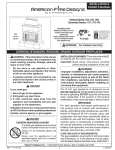
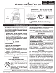
FEATURES:
• CONTROL OPERATED ON/OFF •
• VARIABLE FLAME-HEIGHT REMOTE •
• VARIABLE FLAME HEIGHT CONTROL •
Models:
APK-17(M)(P)
SUITABLE FOR THE FOLLOWING BURNERS:
• PAN BURNERS (P-SERIES) •
• G4 SERIES BURNERS •
• G45 SERIES BURNERS •
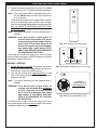
APK-17 PILOT KITS
Important: Read these instructions carefully
before starting installation of the
burner control system.
WARNING
If the information in this manual is not followed
exactly, a fire or explosion may result, causing
property damage, personal injury, or loss of life.
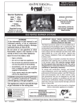
The Peterson Real-Fyre® burner system is to be
installed only in a solid-fuel-burning fireplace with a
working flue constructed of noncombustible material.
Solid fuels shall not be burned in a fireplace where the
unit is installed. The installation, including provisions
for combustion, ventilation air, and required minimum
permanent vent opening, must conform with the
National Fuel Gas Code (ANSI Z223.1/NFPA 54)
and applicable local building codes. In Canada, the
installation must conform with the Natural Gas and
Propane Storage and Handling Installation Code
(CSA-B-149.1). A damper stop clamp is included to
maintain the minimum permanent vent opening and to
prevent full closure of the damper blade. The chimney
damper must be fixed fully opened when burning
the unit. The burner system is designed to burn
with yellow flames; thus, adequate ventilation is
absolutely necessary.
Do not store or use gasoline or other
flammable vapors and liquids in the vicinity
of this or any other appliance.
WHAT TO DO IF YOU SMELL GAS:
• Open a window.
• Do not try to light any appliance.
• Do not touch any electrical switch; do
not use any phone in the building.
• Immediately call the gas supplier from
a neighbor’s phone and follow the gas
supplier’s instructions.
• If you cannot reach the gas supplier,
call the fire department.
Installation and service must be
performed by an NFI Certified or other
qualified professional installer, service
agency, or the gas supplier.
INSTALLER & CONSUMER
These instructions MUST be
retained with this appliance
Robert H. Peterson Co. • 14724 East Proctor Avenue • City of Industry, California 91746
Rev 5 - 1310220810
1
L-A2-256
INSTALLATION &
MODE D'EMPLOI
SYSTÈME DE PILOTE DE SÉCURITÉ DISTANCE DE L'ÉCLAIRAGE AUTOMATIQUE
AVEC TELECOMMANDE VARIABLE DE FLAMME HAUTEUR
D'GAZ NATUREL OU PROPANE
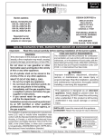
CARACTÉRISTIQUES:
• COMMANDE À ACTION ON / OFF •
Modèles #
APK-17(M)(P)
• VARIABLE DE FLAMME HAUTEUR
DISTANCE •
• CONTRÔLE DE LA HAUTEUR VARIABLE DES
FLAMMES •
ADAPTÉ POUR LES FEUX SUIVANTES:
• BRÛLEURS PAN (P-SERIES) •
• BRÛLEURS SÉRIE G4 •
• G45 FEUX DE LA SÉRIE •
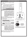
APK-17 KITS DE PILOTES
AVERTISSEMENT
Important: Lire attentivement ces instructions
avant de commencer l'installation du
système de contrôle du brûleur.
Si les informations contenues dans ce manuel
ne sont pas suivies à la lettre, un incendie ou
une explosion pourraient s'ensuivre, causant
des dommages matériels, des blessures ou des
pertes de vie.
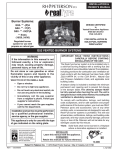
La Peterson réel Fyre système de brûleur® doit être
installé uniquement dans un foyer à combustible solide
qui brûle avec une cheminée de travail construite en
matériaux incombustibles. Les combustibles solides
ne doit pas être brûlé dans un foyer où l'appareil
est installé. L'installation, y compris les dispositions
pour la combustion, l'air de ventilation et d'aération
minimale requise ouverture permanente, doivent
être conformes au Code national du gaz combustible
(ANSI Z223.1/NFPA 54) et aux codes du bâtiment
locaux. Au Canada, l'installation doit être conforme
avec le stockage de gaz naturel et propane et le code
d'installation de manutention (CSA B-149.1). Un collier
d'arrêt d'amortissement est inclus pour maintenir
l'ouverture de ventilation minimum permanent et pour
empêcher la fermeture complète du clapet. Le registre
de cheminée doit être fixé complètement ouvert lors
de la combustion de l'appareil. Le système de brûleur
est conçu pour brûler avec des flammes jaunes; ainsi,
une ventilation adéquate est absolument nécessaire.
Ne pas entreposer ni utiliser d'essence ou
d'autres vapeurs et liquides inflammables à
proximité de cet appareil ou de tout autre.
QUE FAIRE SI UNE ODEUR DE GAZ:
• Ouvrez une fenêtre.
• Ne pas tenter d'allumer d'appareil.
• Ne touchez à aucun interr upteur
électrique; n'utilisez aucun téléphone
dans le bâtiment.
• Appeler immédiatement le fournisseur
de gaz à partir du téléphone d'un voisin
et suivez les instructions du fournisseur
de gaz.
Installation et l'entretien doivent être
effectués par une personne certifiée NFI ou
un autre installateur professionnel qualifié,
une agence de service ou le fournisseur de
gaz.
INSTALLATEUR ET DE CONSOMMATION
Ces instructions doivent être conservées
avec l'appareil
Robert H. Peterson Co. • 14724 East Proctor Avenue • City of Industry, California 91746
Rev 5 - 1310220810
2
L-A2-256
TABLE OF CONTENTS
GETTING STARTED
IMPORTANT INFORMATION ..................................................................................................................... 4
SPECIFICATIONS......................................................................................................................................... 4
REPLACEMENT PARTS LIST ..................................................................................................................... 5
NOTES PAGE ................................................................................................................................................ 6
INSTALLATION
INSTALLATION............................................................................................................................................ 7
PREPARATION......................................................................................................................................... 7
CONVERTING FOR DIFFERENT GAS TYPE ............................................................................................ 7
INSTALL VALVE ....................................................................................................................................... 7
INSTALL FLAME DIVERTER BRACKET ................................................................................................... 8
INSTALL PILOT ASSEMBLY TO BURNER ................................................................................................. 8
CONNECT TO GAS SUPPLY .................................................................................................................... 9
HEAT SHIELD PLACEMENT .................................................................................................................. 10
DECORATIVE MEDIA REPLACEMENT.................................................................................................. 10
CONNECT REMOTE RECEIVER (if equipped)......................................................................................... 10
USE, CARE, & SERVICE
LIGHTING INSTRUCTIONS ..................................................................................................................... 11
LIGHTING THE PILOT .......................................................................................................................... 11
REMOTE LIGHTING (if equipped) .......................................................................................................... 11
MANUAL LIGHTING .............................................................................................................................. 13
PILOT BURNER CHECK/ADJUSTMENT ................................................................................................ 15
SHUTTING DOWN ................................................................................................................................. 15
REMOTE OPERATING INSTRUCTIONS ................................................................................................ 15
ORIENTATION ....................................................................................................................................... 15
FLAME HEIGHT .................................................................................................................................... 15
TROUBLESHOOTING ............................................................................................................................... 17
WARRANTY ............................................................................................................................................... 18
Rev 5 - 1310220810
3
L-A2-256
IMPORTANT INFORMATION
CHECK TO BE SURE THAT THE PROPER FUEL GAS IS BEING USED WITH THIS PILOT KIT.
The installation, including provisions for combustion and ventilation air, must conform with local codes, or in the
absence of local codes, with the National Fuel Gas Code (ANSI Z223.1/NFPA 54).
This component and its individual shutoff valve must be disconnected from the gas-supply piping system when
testing at pressures that exceed 1/2 psig. This is accomplished by closing the gas-supply line valve.
This component must be isolated from the gas-supply piping system by closing its individual manual shutoff
valve during any testing of the gas-supply system at test pressures up to and including 1/2 psig.
A fireplace screen must be in place when the gas burner system is in operation. Unless other provisions for
combustion air are provided, the screen shall have an opening(s) for introduction of combustion air.
WHEN GLASS FIREPLACE ENCLOSURES (DOORS) ARE USED, OPERATE THE BURNER SYSTEM WITH
THE GLASS DOORS FULLY OPEN; BOTH SIDES IF THE FIREPLACE IS A SEE-THROUGH TYPE.
This appliance may be installed in an aftermarket, permanently located, manufactured (mobile) home where not
prohibited by local codes. Installation of appliances designed for manufactured homes or mobile homes must
conform with Manufactured Home Construction and Safety Standard, Title 24 CFR, Part 3280 in the U.S.; or with
CAN/CSA Z240 MH in Canada; or with ANSI/NCSBCS A225.1/NFPA 501A, Manufactured Home Installations
Standard when such as standard is not applicable.
Do not use this appliance if any part has been underwater. Immediately call a qualified service technician to
inspect the appliance and to replace any part of the control system and any gas control that has been underwater.
ALWAYS KEEP GRANULES AND ALL FOREIGN OBJECTS AWAY FROM THE PILOT
ASSEMBLY AND VALVE ASSEMBLY.
IT IS CRITICAL THAT THE HEAT SHIELD BE PLACED CORRECTLY OVER THE VALVE
FOR THE UNIT TO OPERATE CORRECTLY.
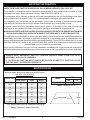
SPECIFICATIONS
Minimum firebox dimensions required for burner system
(with APK valve attached):
Burner size
Min. Firebox Dimensions
Center Width *
Depth
Height
16/19"
30"
11"
18"
18/20"
31"
14"
18"
24"
35"
14"
18"
30"
41"
15"
18"
36"
47"
16"
18"
42"
53"
16"
18"
48"
59"
16"
18"
54"
65"
16"
18"
60"
71"
16"
18"
Model
APK-17
BTUs
Nat.
L.P.
100 k
200 k
Table 2 - Maximum BTUs
Center width
Depth
* This required width allows for centering of the log set.
Table 1 - Minimum Firebox Dimensions
Rev 5 - 1310220810
4
L-A2-256
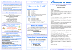
REPLACEMENT PARTS LIST
2
Wire harness to
remote receiver
(if equipped)
4
6
1
3
5
Note: Photos not to scale
Item Description
Rev 5 - 1310220810
Part No.
Qty.
SV-37
SV-37P
1
1
PAC-1NAT
PAC-1LP
1
1
1.
or
Control valve (natural)
Control valve (propane)
2.
or
Pilot assembly (natural)
Pilot assembly (propane)
3.
Flame diverter bracket
SH-1
1
4.
Valve heat shield
HS-35
1
5.
Control knob
KNOB-9
1
6.
Remote kit (if equipped)
VR-1A
1
5
L-A2-256
NOTES PAGE
Please use this page to record any information that you may want to have at hand.
Rev 5 - 1310220810
6
L-A2-256
INSTALLATION
This safety pilot system must be installed by a qualified professional service technician. Instructions
must be followed carefully when installing to ensure proper performance and full benefit from the
burner system and safety pilot system.
These instructions must be used as a supplement to the instructions supplied with the R.H. Peterson burner
system. Follow the burner system instructions and make adjustments as appropriate for the addition of a safety
pilot system. Use gas pipe sealing compound that is resistant to all gasses (or Teflon tape) and apply to all
male pipe connections. Make sure that all connections are tight.
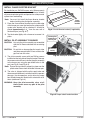
The valve system is shipped pre-assembled for easy
installation onto the burner pan.
Note: Installation is easier when done outside of the
fireplace.
PREPARATION
If the burner that the valve system is to be added to is
already installed; remove all decorative media, set aside to
be reinstalled later, and disconnect the flex connector and
adapter from the burner pan (using the instructions that
came with the original burner).
Fig. 7-1 Pilot conversion (only if applicable)
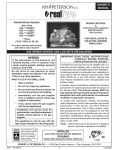
CONVERTING FOR DIFFERENT GAS TYPE
CAUTION: Check to be sure this pilot kit is designed
and labeled for the type of gas (natural or
propane gas) supplied to the fireplace.
The safety pilot kit may require a pilot orifice conversion.
Replace the existing gas orifice with the opposite gas
orifice (contained in the envelope marked "L.P. GAS" or
"NAT GAS") by carefully removing the pilot gas supply line.
Re-attach the pilot gas supply line to the pilot when done.
Reference Fig. 7-1.
CAUTION: During any conversions, all components must
be set/converted for the appropriate gas type
(i.e. burner orifice, regulator, etc.). Contact
your dealer and a qualified professional
service technician.
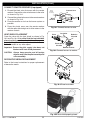
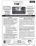
Install shown on
a G45 pan
Attach the valve to the
air mixer/fuel injector by
rotating the burner pan.
Burner
pan
Fuel injector
or air mixer
Valve
INSTALL VALVE
1. Apply gas pipe sealing compound (or Teflon tape) to the
male end of the fuel injector or air mixer on the burner.
Fig. 7-2 Install valve
2. Install the valve to the fuel injector or air mixer by
screwing the pan into the valve (Fig. 7-2). Take care not
to damage the attached pilot assembly when rotating
the burner pan. Be sure all connections are tight.
Important: Ensure the valve is positioned parallel with the
fireplace floor. Adjust as necessary.
Rev 5 - 1310220810
7
L-A2-256
INSTALLATION (Cont.)
INSTALL FLAME DIVERTER BRACKET
For installation on G4/G45 burners only. When properly
installed onto the burner pan, the flame diverter bracket
will promote quicker ignition and protect the safety control
system from overheating.
REAR WALL
BURNER
Burner
pan
PAN
Note: You must first install the flame diverter bracket
before installing the pilot/igniter assembly.
1. Place the flame diverter bracket over the side edge
of the burner pan, near the location the safety control
system pilot bracket will be attached. It should be
placed approximately 1-1/4" from the rear wall of
the burner pan (see Fig. 8-1).
2. Tap the bracket lightly with a hammer to secure it in
place.
INSTALL PILOT ASSEMBLY TO BURNER
1
21-1/2
/4"
FLAME
DIVERTER
Flame
BRACKET
diverter
bracket
Fig. 8-1 Install diverter bracket (if applicable)
Fasten pilot
assembly to
burner pan
CAUTION: Use only the pilot assembly pre-assembled
with this kit. Never substitute with an existing
pilot.
CAUTION: Do not kink or damage the pilot supply tube
and thermocouple lead. Do not unscrew the
gas line from the valve.
1. The pilot assembly comes with two Phillips screws
installed on the long side of the pilot bracket. Remove
the screws and use them to fasten the pilot assembly
to the burner pan using the pre-drilled holes in the
pan (see Fig. 8-2 and Fig. 8-3).
(screw from
inside)
Fig. 8-2 Install pilot assembly
Note: Ensure the insulation is properly in place over the
pilot bracket. Screw from the inside of burner pan.
2. The valve is shipped with the pilot supply tube and
thermocouple lead bent in an ideal manner to prevent
damage / unsafe operation, and to allow for proper
heat shield placement. Maintain this orientation at all
times (reference Fig. 8-3).
WARNING: Keep the pilot assembly clear at all
times. Never cover any part of the pilot
assembly.
Fig. 8-3 Proper tube & lead orientation
Rev 5 - 1310220810
8
L-A2-256
INSTALLATION (Cont.)
CONNECT TO GAS SUPPLY
To connect the valve to the gas supply, the flex connector
kit and component parts will be needed, which are included
with the burner system. Refer to the PARTS LIST in the
instructions supplied with the burner to identify the key
parts needed.
Attach adapter &
flex connector to
nipple on valve
1. MAKE SURE THE FIREPLACE GAS SUPPLY IS
TURNED OFF.
2. Locate the gas-supply stub inside the fireplace and
remove the cap, if attached.
CAUTION:
When removing the cap, make sure the stub
does not turn, loosening the connection inside
the wall.
3. Attach the small adapter (included with burner flex
connector kit) to the gas nipple on the control valve
using a pipe compound resistant to all gasses.Tighten
securely. Then attach one end of the connector to the
small adapter. Tighten securely. See Fig. 9-1.
Fig. 9-1 Install flex connector to valve
4. Place the burner system in the fireplace. Center the
burner in the fireplace.
5. Be sure gas to the fireplace is off. Attach the large
adapter (included with burner flex connector kit) to
the gas-supply stub using a pipe compound resistant
to all gasses. Tighten securely. Then attach the open
end of the flex connector to the large adapter. Tighten
securely.
6. LEAK TEST: Turn on the fireplace gas supply, and test
at all connections for leaks using the appropriate soapy
water solution. If bubbles appear, a leak is present.
Turn off the gas and tighten at all connections. Repeat
until no leaks are present. If a leak persists, turn off
the gas supply and contact the local gas company
or dealer. NEVER USE A FLAME TO CHECK FOR
LEAKS.
7. Follow the instructions supplied with the Peterson
burner system for any additional requirements
regarding specific burner setup and placement.
Rev 5 - 1310220810
9
L-A2-256
INSTALLATION (Cont.)
CONNECT REMOTE RECEIVER (if equipped)
1. Discard the black wires that come with the remote
receiver. Connect the valve wire harness to the valve
as shown in Fig. 10-1.
2. Connect the valve wire harness to the remote receiver
as shown in Fig. 10-2.
(from
remote
receiver)
Connect here
Wire
harness
Valve
3. Place the receiver as far from the burner system as
possible.
4. Place the plastic cover over the remote receiver
with the open side facing front to allow access to the
receiver controls.
Fig. 10-1 Connect harness to valve
Insulation
HEAT SHIELD PLACEMENT
Valve
Cover the valve with the heat shield as shown in Fig.
10-3 and Fig. 10-4. It is critical that the heat shield be
placed correctly over the valve for the unit to operate
properly. Keep the area above the heat shield clear of
decorative media or any other object.
Important: Ensure the pilot supply tube does not
interfere with heat shield placement.
CAUTION: Always keep granules and all foreign
objects away from the pilot assembly and
valve assembly.
Black wire
this side
Red wire
this side
N
AR
LE
J.
AD
ON
TE
MO
RE
F
OF
Remote receiver
Fig. 10-2 Connect harness to receiver
DECORATIVE MEDIA REPLACEMENT
Refer to the burner instructions for proper replacement
of decorative media.
Fig. 10-3 Place heat shield
Fig. 10-4 Heat shield properly placed
Rev 5 - 1310220810
10
L-A2-256
LIGHTING INSTRUCTIONS
FOR YOUR SAFETY READ BEFORE LIGHTING
WARNING: If you do not follow these instructions exactly, a fire or explosion may result causing property
damage, personal injury or loss of life.
A. Use only your hand to push in or turn the gas control knob. Never use tools. If the knob will not push in or turn
by hand, don't try to repair it. Call a qualified professional service technician. Excessive force or attempted
repair may result in fire or explosion.
B. BEFORE OPERATING, smell all around the appliance area for gas. Be sure to smell next to the floor
because some gas is heavier than air and will settle on the floor.
WHAT TO DO IF YOU SMELL GAS
• Do not light any appliance.
• Do not touch any electric switch; do not use any phone in your building.
• Immediately call your gas supplier from a neighbor's phone. Follow the gas supplier's instructions.
If you cannot reach your gas supplier, call the fire department.
C. The burner system has a pilot that can be lit by hand using a match or long-necked lighter. When lighting
the pilot, follow these instructions exactly.
D. Do not use this appliance if any part has been under water. Immediately call a qualified service technician
to inspect the appliance and to replace any part of the control system and any gas control which has been
under water. Attempted operation may result in fire or explosion resulting in property damage, personal
injury or loss of life.
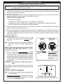
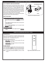
LIGHTING THE PILOT
OFF
OFF
ON
2. Turn the control knob counterclockwise to PILOT
(Fig. 11-1). Push the control knob firmly and fully
in and hold. Hold a long fireplace match or lighter
near the thermocouple to light the pilot. Continue to
hold the control knob in for approximately 60 seconds
after the pilot is lit, then release the knob. The pilot
will remain lit.
1. Turn knob clockwise
to OFF prior to lighting
the pilot.
2.
Tu r n k n o b
counterclockwise to
PILOT position. Press
knob in, push piezo
button, and hold for
60 seconds while
lighting pilot.
Fig. 11-1 Control knob detail (OFF, PILOT)
WARNING: If the pilot fails to light repeat steps 1
and 2.
If the pilot fails to light after several tries, turn the control
knob to OFF and contact a qualified professional service
technician.
ADJ.
LEARN
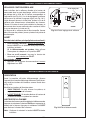
REMOTE LIGHTING (if equipped)
Note: Step 1 may not be required if previously done during
an earlier lighting.
1. Ensure the pilot is burning. Then locate the 3-position
switch on the remote receiver (see Fig. 11-2), and slide
the switch to the REMOTE position.
11
ON
F
Allow five (5) minutes for any gas in the unit to dissipate.
IF YOU SMELL GAS, SEE STEP B ABOVE. If you don’t
smell gas, go on to step 2.
PILOT
PILOT
Note: The control knob cannot be turned from PILOT to
OFF unless the knob is pushed in slightly. Do not
force.
PILOT
ON
OFF
PILOT
1. Locate the valve on the side of the unit. Push in the
gas control knob slightly and turn clockwise to OFF
(Fig. 11-1).
OFF REMOTE
ON
Fig. 11-2 Remote receiver detail (REMOTE)
INSTRUCTIONS D'ALLUMAGE
POUR VOTRE SÉCURITÉ LISEZ AVANT D'ALLUMER
AVERTISSEMENT: Si vous ne suivez pas ces instructions à la lettre, un incendie ou une explosion entraînant
des dommages matériels, des blessures ou des pertes de vie.
A. N'utilisez que votre main pour enfoncer ou tourner le bouton de contrôle du gaz. Ne jamais utiliser d'outils. Si le
bouton ne sera pas enfoncer ou à tourner à la main, n'essayez pas de le réparer. Appelez un technicien de service
qualifié. Une force excessive ou une tentative de réparation pourrait provoquer un incendie ou une explosion.
B. AVANT DE FAIRE FONCTIONNER, sentez autour de l'appareil pour le gaz. Assurez-vous de sentir près du
plancher, car certains gaz sont plus lourds que l'air et se déposent sur le sol.
QUE FAIRE SI UNE ODEUR DE GAZ
• Ne pas allumer l'appareil.
• Ne touchez à aucun interrupteur électrique; n'utilisez aucun téléphone dans votre bâtiment.
• Appelez immédiatement votre fournisseur de gaz à partir du téléphone d'un voisin. Suivez les instructions du
fournisseur de gaz. Si vous ne pouvez joindre votre fournisseur de gaz, appeler les pompiers.
C. Le système de brûleur a un pilote qui peut être allumée en utilisant une allumette ou briquet long cou. Pour
allumer la veilleuse, suivez ces instructions à la lettre.
D. Ne pas utiliser cet appareil si une partie quelconque a été submergée. Appelez immédiatement un technicien de
service qualifié pour inspecter l'appareil et pour remplacer toute pièce du système de contrôle et toute commande
de gaz qui a été sous l'eau. Tentative d'opération peut entraîner un incendie ou une explosion entraînant des
dommages matériels, des blessures ou des pertes de vie.
ALLUMAGE DE LA VEILLEUSE
AVERTISSEMENT: Si le pilote ne s'allume pas, répétez
les étapes 1 et 2.
Si le pilote ne s'allume pas après plusieurs essais, tournez
le bouton de commande sur OFF et contactez un technicien
qualifié.
1. Tourner le bouton
dans le sens horaire
en position OFF avant
d'allumer la veilleuse.
OFF
2.
To u r n e r l e
bouton dans le sens
antihoraire àlaposition
PILOT. Appuyez sur
le bouton, poussez
le bouton piezo, et
maintenez pendant
60 secondes allumer
la veilleuse.
Fig. 12-1 Détail bouton de commande
(OFF, PILOTE)
ADJ.
LEARN
DISTANCE DE L'ÉCLAIRAGE (le cas échéant)
Note: Étape 1 ne peut être exigé s'il a déjà été fait au cours
d'un éclairage plus tôt.
1. Assurer la veilleuse est allumée. Ensuite, localisez
le commutateur à 3 positions sur le récepteur de la
télécommande (voir Fig. 12-2), Et faites glisser le
commutateur sur la position REMOTE.
12
ON
PILOT
PILOT
ON
2. Tournez le bouton de réglage dans le sens antihoraire
pour PILOTE (Fig. 12-1). Appuyez sur le bouton de
commande fermement et pleinement enfoncée. Tenir
un long match de cheminée ou un briquet à proximité
du thermocouple pour allumer la veilleuse. Continuez
à tenir le bouton de commande pendant environ 60
secondes après que le pilote est allumé, puis relâchez
le bouton. Le pilote reste allumé.
OFF
ON
Attendez cinq (5) minutes pour n'importe quel gaz dans
l'unité de se dissiper. S'IL YA UNE ODEUR DE GAZ, voir
l'étape B CI-DESSUS. Si vous ne sentez pas de gaz, passez
à l'étape 2.
PILOT
PILOTE
PILOT
Note: Le bouton de commande ne peut être activée à partir
PILOTE sur OFF si le bouton est enfoncé légèrement.
Ne pas forcer.
OFF
OFF
OFF
1. Localiser la vanne sur le côté gauche de l'appareil. Appuyer
sur le bouton de contrôle du gaz et tourner dans le sens
horaire en position OFF (Fig. 12-1).
OFF REMOTE
ON
Fig. 12-2 Détail récepteur de télécommande
(REMOTE)
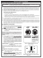
LIGHTING INSTRUCTIONS (cont.)
2. Locate the remote transmitter and press the ON/HI
button (see Fig. 13-1).The ignition sequence will begin.
Note: Upon initial use or after an extended period of no
use, the ON/HI button may have to be pressed for
up to 3 seconds.
ON/HI
The remote receiver will emit an audible "beep"; then the
valve will automatically open and the burner will light.
Adjust to the desired setting with the remote transmitter.
See the REMOTE OPERATING INSTRUCTIONS
section for details.
LO/OFF
Note: The ignition sequence will take approximately 5
seconds.
WARNING: If the burner fails to light within 10
seconds, press and hold the OFF button
on the remote transmitter and/or slide the
switch to the OFF position. Allow five (5)
minutes for any gas in the unit to dissipate,
then repeat steps 1 and 2 above. IF YOU
SMELL GAS, SEE STEP B AT BEGINNING
OF LIGHTING INSTRUCTIONS.
Fig. 13-1 Remote transmitter detail
ADJ.
If the burner fails to light after several tries, turn all control/
remote system components to OFF and contact a qualified
professional service technician.
LEARN
OFF REMOTE
ON
MANUAL LIGHTING
OFF
ON
PILOT
Note: The ignition sequenceOFF
will take approximately 5
PILOT
seconds.
WARNING: If the burner fails to light within 10
seconds, turn the control knob clockwise
to PILOT. Allow five (5) minutes for any
gas in the unit to dissipate, then repeat
step 2 above. IF YOU SMELL GAS, SEE
STEP B AT BEGINNING OF LIGHTING
INSTRUCTIONS.
ON
If the burner fails to light after several tries, push in the
control knob slightly and turn clockwise to OFF, and contact
a qualified professional service technician.
13
ON
ON
PILOT
2. Turn the gas control knob counterclockwise to ON
(Fig. 13-3) to ignite the burner. The valve will open and
the burner will light.
Fig. 13-2 Remote receiver (OFF for Manual Light)
OFF
1. Ensure the pilot is burning. If equipped, locate the
3-position switch on the remote receiver (see Fig. 13-2),
and slide the switch to the OFF position.
For Manual
Lighting, turn knob
counterclockwise to
ON position.
Fig. 13-3 Control knob detail (ON)
INSTRUCTIONS D'ALLUMAGE (cont.)
2. Localisez la télécommande et appuyez sur le bouton
ON/HI (voir Fig. 14-1). La séquence d'allumage
commencera.
Note: Lors de la première utilisation ou après une longue
période de non utilisation, la touche ON/HI bouton
peut être pressé pendant 3 secondes.
ON/HI
LO/OFF
Le récepteur de la télécommande émettra un «bip»
sonore, puis la vanne s'ouvre automatiquement et le
brûleur s'allume. Choisissez le réglage souhaité avec
la télécommande. Voir la section INSTRUCTIONS DE
FONCTIONNEMENT A DISTANCE pour plus de détails.
Note: La séquence d'allumage dure environ 5 secondes.
WARNING: Si le brûleur ne s'allume pas dans les
10 secondes, appuyez et maintenez le
bouton OFF de la télécommande, ou
faites glisser le commutateur sur la
position OFF. Attendez cinq (5) minutes
pour n'importe quel gaz dans l'unité à se
dissiper, puis répétez les étapes 1 et 2 cidessus. S'IL YA UNE ODEUR DE GAZ, voir
étape b AU DÉBUT DE INSTRUCTIONS
D'ALLUMAGE.
Fig. 14-1 Détail télécommande
ADJ.
Si le brûleur ne s'allume pas après plusieurs essais, tournez
tout contrôle / composants du système à distance sur OFF
et contacter un technicien professionnel qualifié.
ALLUMAGE MANUEL
LEARN
OFF REMOTE
ON
Fig. 14-2 Récepteur de la télécommander
Note: La séquence d'allumage dure environ 5 secondes.
ON
WARNING: Si le brûleur ne s'allume pas dans les
10 secondes, tournez le bouton de
commande vers la droite pour PILOT.
Attendez cinq (5) minutes pour n'importe
quel gaz dans l'unité à se dissiper, puis
répétez l'étape 2 ci-dessus. S'IL YA UNE
ODEUR DE GAZ, voir étape b AU DÉBUT
DE INSTRUCTIONS D'ALLUMAGE.
Si le brûleur ne s'allume pas après plusieurs tentatives,
appuyez sur le bouton de commande et tournez légèrement
à OFF et contactez un technicien qualifié.
14
ON
SUR
ON
PILOT
OFF
ON
PILOT
2. Tournez le bouton de contrôle du gaz dans le sens
OFF
antihoraire sur ON (Fig. 14-3)
pour allumer le brûleur.
PILOT
La vanne s'ouvre et le brûleur s'allume.
(OFF pour Light Manuel)
OFF
1. Assurer la veilleuse est allumée. Si vous êtes équipé,
localisez le commutateur à 3 positions sur le récepteur
de la télécommande (voir Fig. 14-2), Et faites glisser
le commutateur sur la position OFF.
Pour l'éclairage
manuel, tournez
le bouton dans le
sens antihoraire à la
position ON.
Fig. 14-3 Détail bouton de commande (SUR)
LIGHTING INSTRUCTIONS (cont.)
PILOT BURNER CHECK/ADJUSTMENT
Pilot adjustment screw
With the pilot burner lit and the control knob in the pilot
position, check the pilot system for proper flame size and
appearance (see Fig. 15-1). The pilot adjustment screw is
located on the front of the gas valve (see Fig. 15-1). Using a
small flat head screwdriver, adjust the pilot screw to properly
size the flames. Turning the screw clockwise will lower the
flames, and turning it counterclockwise will raise them. Be
careful not to back the screw out of its threads.
The pilot flame should be a quiet, soft blue flame with yellow
tipping that encircles the thermocouple tip.
Thermocouple
PILOT
VALVE
Fig. 15-1 Pilot adjustment detail
SHUTTING DOWN
To extinguish the main burner (pilot will remain lit):
• For a remote shut down, press and hold the LO/OFF
button on the remote transmitter until the burner shuts
off.
If your remote is lost, slide the switch on the receiver
to the OFF position.
• For a manual shutdown, turn the control knob
clockwise to PILOT.
To extinguish the pilot:
• Push in the control knob slightly and turn clockwise
to OFF.
REMOTE OPERATING INSTRUCTIONS
ORIENTATION
Prior to remote transmitter use, light the appliance per the
REMOTE LIGHTING section. Familiarize yourself with the
transmitter keys, as illustrated in Fig. 15-2.
ON/HI
Identify the two transmitter keys:
• ON/HI KEY: This keys turn the system ON, and
increases the flame height.
LO/OFF
• LO/OFF KEY: This keys decreases the flame height
and turn the system OFF.
FLAME HEIGHT
The flame height may be adjusted via the remote transmitter.
Press and hold the ON/HI key to increase the flame height.
Press and hold the LO/OFF key to decrease the flame height.
Note: Continuing to hold the LO/OFF key will turn off the
burner.
15
Fig. 15-2 Remote transmitter detail
INSTRUCTIONS D'ALLUMAGE (cont.)
VEILLEUSE CONTROLE/REGLAGE
Vis de réglage de
Avec le brûleur de la veilleuse allumée et le bouton de
commande dans le poste de pilotage, vérifier le système
de pilotage de la taille de la flamme correspondant et
l'apparence (voir Fig. 16-1). La vis de réglage de la veilleuse
se trouve sur la face de la soupape à gaz (voir Fig. 16-1).
L'aide d'un petit tournevis à tête plate, ajustez la vis de la
veilleuse pour dimensionner correctement les flammes.
Tourner la vis dans le sens horaire réduira les flammes, et
en tournant dans le sens antihoraire leur susciterai. Veillez
à ne pas desserrer la vis de ses fils.
La flamme de la veilleuse devrait être tranquille, flamme
bleu pâle avec des pointes jaunes qui entoure la pointe du
thermocouple.
Thermocouple
PILOTE
VANNE
Fig. 16-1 Détail réglage de la veilleuse
ARRÊT
Pour éteindre le brûleur principal (pilote restera allumé):
• Pour éteindre à distance, appuyez et maintenez le
bouton LO/OFF sur la télécommande jusqu'à ce que
le brûleur est éteint.
Si la télécommande est perdue, faites glisser
l'interrupteur du récepteur sur la position OFF.
• Pour un arrêt manuel, tournez le bouton de
commande vers la droite pour PILOT.
Pour éteindre le pilote:
• Appuyez sur le bouton de commande et tournez
légèrement sur OFF.
MODE D'EMPLOI À DISTANCE
ORIENTATION
Avant la première utilisation télécommande, allumez
l'appareil pour la section d'éclairage à distance. Familiarisezvous avec les touches de l'émetteur, comme illustré dans
la Fig. 16-2.
Identifier les touches de l'émetteur deux:
ON/HI
LO/OFF
• ON/HI TOUCHE: Ce clés allumer le système, et
augmente la hauteur de la flamme.
• LO/OFF TOUCHE: Ce touches diminue la hauteur de
la flamme et mettre le système hors tension.
HAUTEUR DE LA FLAMME
La hauteur des flammes peut être réglée via la télécommande.
Appuyez et maintenez le bouton ON/HI pour augmenter la
hauteur de la flamme. Appuyez et maintenez la LO/OFF
pour diminuer la hauteur de la flamme.
Note: Continuer à maintenir la touche LO/OFF éteindre
le brûleur.
16
Fig. 16-2 Détail télécommande
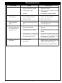
TROUBLESHOOTING
PROBLEM
CAUSE
SOLUTION
a. Obstruction in pilot gas supply or
pilot gas-supply line is kinked
a. Clear out obstruction. Replace pilot gassupply line if kinked
b. Inadequate gas supply
b. Have gas pressure checked by installer
or gas supplier
c. Air in line
c. Air should clear; attempt to relight
a. Thermocouple connection to valve
either too tight or too loose
a. Thermocouple should be finger tight and
then 1/8" turn with a wrench
b. Bad thermocouple
b. Replace thermocouple
3. Log set extinguishes
a few minutes after
lighting
a. Inadequate gas supply causes
pilot flame to reduce after burner
lights
a. Using pilot adjustment, increase gas to
pilot. Pilot flame must be in contact with
the thermocouple tip.
4. Log set extinguishes
after burning for some
time (approximately 10
minutes to 1 hour)
a. Thermocouple has overheated;
glass doors are closed
a. Be sure glass doors are open during
operation
b. Thermocouple has overheated;
insulation pad is not in place
b. Be sure that the insulation pad is in place
between the burner pan and the pilot
bracket
c. Thermocouple has overheated;
burner flames are heating the
thermocouple cold junction
c. Be sure the pilot assembly and the flame
diverter are in their proper position.
Re-arrange logs so that flame is not
deflected to the thermocouple.
a. Valve over heated
a. Ensure that the valve heat shield is
properly placed and no gas leaks are
present at the valve gas fittings
1. Pilot will not light
2. Pilot will not stay lit after
releasing knob
5. Valve will not turn "OFF"
with remote
b. Low batteries
b. Replace batteries in remote receiver
17
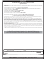
WARRANTY
PETERSON VENTED DECORATIVE GAS APPLIANCE
LIMITED WARRANTY
Robert H. Peterson Co. ("RHP") warrants your Real Fyre® vented decorative gas appliance to be free from defects in material and
workmanship.
Peterson vented gas logs are warranted for as long as you own them (lifetime).
Peterson vented burner assemblies are WARRANTED for TEN (10) YEARS. Peterson vented outdoor stainless-steel burner
assemblies are warranted for FIVE (5) YEARS.
Peterson glass, gems, nuggets are warranted for FIVE (5) YEARS.
SPK-26 controls are warranted for THREE (3) YEARS.
APK-17 controls (including -17 valve) are warranted for TWO (2) YEARS.
All other Peterson valves, pilots, and controls are warranted for ONE (1) YEAR (excluding batteries).
A COPY OF YOUR SALES SLIP FOR PROOF OF PURCHASE IS REQUIRED
This warranty applies to the original purchaser for products installed in the United States or Canada and operated and maintained as intended for
single family residential usage. It commences on the date of purchase and is valid only with proof of purchase.
This warranty does not cover components becoming defective through negligence, misuse, use not in compliance with the Installation & Owner’s
Manual, accidental damage, improper handling, improper storage, improper installation, lack of required routine maintenance (as specified in the
Installation & Owner’s Manual), electrical damage, local gas impurities or failure to protect against combustibles. Product must be installed (and gas
must be connected) as specified in the Installation & Owner’s Manual by a qualified professional installer. Modifications which are not specifically
authorized will void this warranty. Accessories, parts, valves, remotes, etc when used must be Peterson product or warranty is void. Warrantied items
will be repaired or replaced at Peterson’s sole discretion.
This warranty does not apply to rust, corrosion, oxidation, or discoloration unless the affected component becomes inoperable. This warranty does
not cover labor or labor related charges.
This warranty specifically excludes liability for indirect, incidental, or consequential damages. Some states and provinces do not allow the exclusion
or limitation of incidental or consequential damages, so the above exclusion may not apply to you. This warranty gives you specified legal rights, and
you may have other rights that vary from state to state or province.
For additional information regarding this warranty, or to place a warranty claim, contact the R. H. Peterson dealer where the product was purchased.
TO REGISTER YOUR PRODUCT ONLINE GO TO: WWW.RHPETERSON.COM,
AND CLICK ON PRODUCT REGISTRATION. THANK YOU FOR YOUR PURCHASE.
Quality Check
Date:_________________
Leak Test:
________________ Burn Test: _________________ Gas Type:
Inspector:
________________
Robert H. Peterson Co. • 14724 East Proctor Avenue • City of Industry, CA 91746
18
Nat. / L.P.