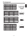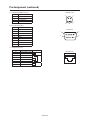
1
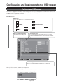
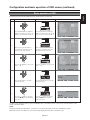
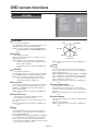
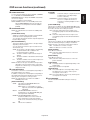
LCD Display Monitor MODEL Features ............................................................................................................................................................................................... English-2 Important Information ............................................................................................................................................................................ English-3 Declaration ............................................................................................................................................................................................ English-5 Safety Precautions, Maintenance & Recommended Use ..................................................................................................................... English-6 Contents ............................................................................................................................................................................................... English-7 Parts Name and Functions .................................................................................................................................................................... English-8 Buttons, Switch, and Indicator............................................................................................................................................... English-8 Connectors and Terminals ..................................................................................................................................................... English-9 Wireless Remote Control ....................................................................................................................................................... English-10 How to Use the Wireless Remote Control ............................................................................................................................. English-11 Preparation for use ................................................................................................................................................................................ English-12 Flow of preparation ................................................................................................................................................................ English-12 [P-1] Preparation for installation ......................................................................................................................................................... English-13 Determine the installation location ......................................................................................................................................... English-13 Ventilation requirements for enclosure mounting .................................................................................................................. English-13 To avoid the monitor from falling ........................................................................................................................................... English-13 [P-2] Installing the monitor ................................................................................................................................................................. English-14 Installing and removing the stands ........................................................................................................................................ English-14 Using the wall mount or ceiling mount................................................................................................................................... English-14 Preventing the handles from touching the wall ...................................................................................................................... English-15 Removing the stand guide frames ......................................................................................................................................... English-15 Using the wall mount spacers ................................................................................................................................................ English-15 Installing in the portrait or face-up position ........................................................................................................................... English-16 Attaching the corner protectors ............................................................................................................................................. English-16 Using the monitor without the bezel ...................................................................................................................................... English-17 [P-3] Installing the optional speakers ................................................................................................................................................. English-18 [P-4] Connection procedure ............................................................................................................................................................... English-19 Wiring diagram ....................................................................................................................................................................... English-19 Prevention of disconnection of HDMI cable .......................................................................................................................... English-20 Connecting with a computer (analog connection) ................................................................................................................. English-21 Connecting with a computer (digital connection) .................................................................................................................. English-22 Connecting a video device (component video/HDMI device) ................................................................................................ English-23 Connecting a video device (composite video/S video device)/stereo amplifier .................................................................... English-24 [P-5] Installing the expansion module ................................................................................................................................................ English-25 Installation of the expansion module ..................................................................................................................................... English-25 SDI for long-distance connection or multiple-monitor connection ........................................................................................ English-25 Connecting OPS-compliant computer................................................................................................................................... English-26 [P-6] Connecting RS-232C ................................................................................................................................................................. English-27 Monitor control via RS-232C ................................................................................................................................................. English-27 [P-7] Connecting LAN......................................................................................................................................................................... English-28 Monitor connection using LAN .............................................................................................................................................. English-28 [P-8] Connecting a USB device .......................................................................................................................................................... English-29 Connecting multiple USB devices using the USB hub function ............................................................................................ English-29 [P-9] Connecting the power cord to the monitor................................................................................................................................ English-30 Connecting the power source ................................................................................................................................................ English-30 How to Use............................................................................................................................................................................................ English-31 Flow of How to Use................................................................................................................................................................ English-31 [U-1] Turning on all the connected devices ........................................................................................................................................ English-32 Turning on external devices ................................................................................................................................................... English-32 Turning on the monitor ........................................................................................................................................................... English-32 Power Management Function ................................................................................................................................................ English-33 [U-2] Selecting the video input ........................................................................................................................................................... English-34 [U-3] Controlling the external devices ................................................................................................................................................ English-35 [U-4] Selecting the OSD language ...................................................................................................................................................... English-35 [U-5] Auto-setup ................................................................................................................................................................................. English-36 [U-6] Selecting the picture mode ........................................................................................................................................................ English-37 [U-7] Screen adjustment ..................................................................................................................................................................... English-37 [U-8] Picture adjustment ..................................................................................................................................................................... English-38 [U-9] Speaker setting .......................................................................................................................................................................... English-38 [U-10] Volume, balance, and tone control ............................................................................................................................................ English-39 [U-11] Schedule setting ........................................................................................................................................................................ English-40 How to set up schedule ......................................................................................................................................................... English-41 [U-12] Remote control .......................................................................................................................................................................... English-42 RS-232C Remote control ....................................................................................................................................................... English-42 LAN Remote control............................................................................................................................................................... English-44 [U-13] Setting the USB hub .................................................................................................................................................................. English-45 Configuration and basic operation of OSD screen ............................................................................................................................... English-46 Configuration of OSD screen ................................................................................................................................................. English-46 Basic operation of OSD ......................................................................................................................................................... English-47 OSD screen functions ........................................................................................................................................................................... English-48 Other functions ...................................................................................................................................................................................... English-58 Picture size ............................................................................................................................................................................. English-58 Picture mode .......................................................................................................................................................................... English-58 Control Lock mode ................................................................................................................................................................ English-58 OSD information..................................................................................................................................................................... English-58 Audio input change ................................................................................................................................................................ English-59 Supplemental information of the auto brightness function .................................................................................................... English-60 PIP, POP function .................................................................................................................................................................. English-61 Remote control numbering function ...................................................................................................................................... English-62 Troubleshooting .................................................................................................................................................................................... English-63 Specifications ........................................................................................................................................................................................ English-64 Pin Assignment ..................................................................................................................................................................................... English-65 English-1 English Index Features Industry-use LED backlight adopted LED backlight panel Power-on Delay Page 64 Commercial grade panel adopting the LED backlight. With the LED backlight, the monitor has achieved low power consumption and eliminated mercury. The slim monitor design allows installation in more various environments than the conventional monitors. High-quality LCD panel which provides a wide variety of contents and messages clearly Full HD panel Page 64 The MDT552S panel reproduces images from video and computer signals with precision and clarity, delivering full 1920 x 1080 high-definition resolution. Page 57 For installations employing numerous monitors, the power-on delay function can power up the monitors sequentially with delay between 2-50 seconds after the power is applied. Using this function can prevent inrush current problems and reduce the overall electrical load requirements when a single power supply is used. LAN Control Pages 28, 44, and 54 You can efficiently and centrally control multiple monitors for reconfiguration and remote diagnosis by sending control commands from a computer via a LAN network. The user can choose to use Mitsubishi protocol to control this monitor, or other popular protocols including Crestron’s RoomView TM and AMX’s Device Discovery. Brightness Compensation by the Ambient Light Sensors for Enhanced Visibility and Lower Power Consumption Ambient Light Sensors (Brightness sensors) Enhanced Display Functionality for Various Commercial Use/Support for System Configuration Suitable for Diversified Applications Tiling Capability with Frame compensation Page 57 Up to 25 panels (5 wide x 5 high) can be combined to create a single large image (i.e., video wall) or other high-impact signage. A frame compensation function is incorporated to compensate the width of panel bezels so that images are displayed with the utmost accuracy. PIP, POP and Side-by-side Pages 10, 52, and 61 Pages 8 and 60 Automatic screen brightness adjustment for enhanced visibility and lower power consumption. The ambient light sensors on the front and rear of the monitor detect not only the light reflected on the front but also from the rear to automatically adjust the image brightness for optimum viewing. The screen is always easy to view in spite of brightness variation during the day or night. Others Picture-In-Picture and Picture-Outside-Picture are available when you want to display video content from a video input source in the sub picture and display the PC input source in the main picture, and vice versa. The native resolution as high as 1920 x 1080 can display these two input sources in the Side-by-side mode, ideal for broadcasting and videoconferencing applications. DisplayPort Digital Zoom Built-in Speakers Page 50 Pages 9 and 22 DisplayPort-compliant terminal is provided. The monitor is equipped with a terminal supporting DisplayPort, a digital interface standard. You can transmit video signals over a single cable of max. 15-meters long. Pages 8 and 38 Zoom mode for expanding 4:3 image to 16:9. Various zoom modes are provided and it is possible to expand 4:3 aspect ratio images to 16:9. In addition, you can select the dynamic display mode to display naturally widened images with different zooming rates around the screen center and screen edges. You can also optimally change the image size diagonally, horizontally, and vertically. This monitor offers built-in stereo speakers to deliver audio messages. Optional external stereo speakers can also be used. The user have the option to switch between using external or built-in speakers from the menu. Expansion slot allowing installation of expansion modules according to applications Closed Caption Option Slot Page 25 You can mount an expansion module recommended by Mitsubishi on the monitor. With such expansion module, you can expand the functionality of the monitor according to the purpose of use. SDI Connection (option) Page 25 The SDI BOX receives SD-SDI, HD-SDI, and 3G-SDI signals at a maximum speed of 2.970 Gbit/s and displays them on the monitor. A single image is distributed to multiple monitors that are daisy-chained via SDI cables (BNC). Various Management Functions Supporting Efficient Operation and Management Programmable Scheduling Function Pages 40, 41, and 55 The monitor’s operating schedule can be programmed for up to seven different scheduled time intervals by time, day of the week and input port. This allows video content from different inputs to be displayed on certain monitors within the same installation according to the schedule, and extends the monitor’s life and saves the power by turning it off during those hours or days it is not in use. Screen-saver Functions Remote Control Pages 10 and 11 A wireless remote control is supplied to control the various functions of this monitor, including power on/off, input select, and menu access. Page 57 You can display captions. When closed-caption is encoded with the video signal, the user can select to display or hide the caption on screen. This monitor is compliant with EIA-608-A. USB hub function Page 57 Multiple USB devices can be connected to the computer. The monitor is equipped with the USB hub having 2 self-powered downstream ports, where the USB devices can be connected. You will find this function convenient when mounting a device such as a digital camera and a touch-panel unit on the monitor. Super Resolution (image conversion) technique Page 49 Still images/natural images and video content are displayed with enhanced clarity based on the super resolution settings. In addition, the monitor is equipped with the resolution recognition function that recognizes the resolution of the input image and automatically applies the effect depending on the recognized resolution. Daisy Chain Connection (DVI-D) Page 22 By connecting the DVI-D OUT connectors and the DVI-D IN connectors using DVI-D cables (commercially available), you can transmit video signals to up to 4 monitors (when using 2-meter cables). This function is useful in supplying a video signal to multiple monitors. Page 53 To reduce image persistence and maximize the panel life in demanding signage applications, this product is equipped with four screen-saver functions. • GAMMA • COOLING FAN • BRIGHTNESS • MOTION English-2 Canadian Department of Communications Compliance Statement DOC: This Class A digital apparatus meets all requirements of the Canadian Interference-Causing Equipment Regulations. C-UL: Bears the C-UL Mark and is in compliance with Canadian Safety Regulations according to CAN/CSA C22.2 No. 60950-1. FCC Information 1. Use the attached specified cables with the MDT552S (A2129) color monitor so as not to interfere with radio and television reception. (1) Please use the supplied power cord or equivalent to ensure FCC compliance. (2) Please use the supplied shielded video signal cable, 15-pin mini D-SUB to 15-pin mini D-SUB. 2. This equipment has been tested and found to comply with the limits for a Class A digital device, pursuant to Part 15 of the FCC Rules. These limits are designed to provide reasonable protection against harmful interference when the equipment is operated in a commercial environment. This equipment generates, uses, and can radiate radio frequency energy and, if not installed and used in accordance with the instruction manual, may cause harmful interference to radio communications. Operation of this equipment in a residential area is likely to cause harmful interference in which case the user will be required to correct the interference at his own expense. 3. You are cautioned that changes or modifications not expressly approved by the party responsible for compliance could void your authority to operate the equipment. Windows is a registered trademark of Microsoft Corporation. HDMI, the HDMI logo, and High-Definition Multimedia Interface are trademarks or registered trademarks of HDMI Licensing LLC in the United States and other countries. VESA, DisplayPort, and the DisplayPort icon are trademarks or registered trademarks of Video Electronics Standards Association in the United States and other countries. Intel is a trademark of Intel Corporation in the United States and other countries. Crestron, Crestron RoomView and RoomView are trademarks or registered trademarks of Crestron Electronics, Inc. in the United States and other countries. AMX is a trademark or registered trademark of AMX, LLC in the United States and other countries. All other brands and product names are trademarks or registered trademarks of their respective owners. English-3 English Important Information Important Information (continued) WARNING TO PREVENT FIRE OR SHOCK HAZARDS, DO NOT EXPOSE THIS UNIT TO RAIN OR MOISTURE. ALSO, DO NOT USE THIS UNIT’S POLARIZED PLUG WITH AN EXTENSION CORD RECEPTACLE OR OTHER OUTLETS UNLESS THE PRONGS CAN BE FULLY INSERTED. REFRAIN FROM OPENING THE CABINET AS THERE ARE HIGH VOLTAGE COMPONENTS INSIDE. REFER SERVICING TO QUALIFIED SERVICE PERSONNEL. CAUTION CAUTION: TO REDUCE THE RISK OF ELECTRIC SHOCK, MAKE SURE POWER CORD IS UNPLUGGED FROM WALL SOCKET. TO FULLY DISENGAGE THE POWER TO THE UNIT, PLEASE DISCONNECT THE POWER CORD FROM THE AC OUTLET. DO NOT REMOVE COVER (OR BACK). NO USER SERVICEABLE PARTS INSIDE. REFER SERVICING TO QUALIFIED SERVICE PERSONNEL. This symbol warns user that uninsulated voltage within the unit may have sufficient magnitude to cause electric shock. Therefore, it is dangerous to make any kind of contact with any part inside this unit. This symbol alerts the user that important literature concerning the operation and maintenance of this unit has been included. Therefore, it should be read carefully in order to avoid any problems. English-4 Declaration We hereby certify that the color monitor MDT552S (A2129) is in compliance with Council Directive 2006/95/EC: — EN 60950-1 Council Directive 2004/108/EC: — EN 55022 — EN 61000-3-2 — EN 61000-3-3 — EN 55024 and marked with Mitsubishi Electric Corporation 2-7-3, Marunouchi, Chiyoda-Ku Tokyo 100-8310, Japan Warning This is a Class A product. In a domestic environment this product may cause radio interference, in which case the user may be required to take adequate measures. Declaration of the Manufacturer Note: This symbol mark is for EU countries only. This symbol mark is according to the directive 2002/96/EC Article 10 Information for users and Annex IV, and/or to the directive 2006/66/EC Article 20 Information for end-users and Annex II. Your MITSUBISHI ELECTRIC product is designed and manufactured with high quality materials and components which can be recycled and/or reused. This symbol means that electrical and electronic equipment, batteries and accumulators, at their end-of-life, should be disposed of separately from your household waste. If a chemical symbol is printed beneath the symbol shown above, this chemical symbol means that the battery or accumulator contains a heavy metal at a certain concentration. This will be indicated as follows: Hg: mercury (0,0005%), Cd: cadmium (0,002%), Pb: lead (0,004%) In the European Union there are separate collection systems for used electrical and electronic products, batteries and accumulators. Please, dispose of this equipment, batteries and accumulators correctly at your local community waste collection/recycling centre. Please, help us to conserve the environment we live in! English-5 English Declaration of the Manufacturer Safety Precautions, Maintenance & Recommended Use FOR OPTIMUM PERFORMANCE, PLEASE NOTE THE FOLLOWING WHEN SETTING UP AND USING THE LCD COLOR MONITOR: • • • • • • • • • • • • • • • • • • • DO NOT REMOVE MONITOR BACK COVER. There are no user serviceable parts inside and opening or removing covers may expose you to dangerous shock hazards or other risks. Refer all servicing to qualified service personnel. Do not spill any liquids into the cabinet or use your monitor near water. Do not insert objects of any kind into the cabinet slots, as they may touch dangerous voltage points, which can be harmful or fatal or may cause electric shock, fire or equipment failure. Do not place any heavy objects on the power cord. Damage to the cord may cause shock or fire. Do not place this product on a sloping or unstable cart, stand or table, as the monitor may fall, causing serious damage to the monitor. When operating the LCD monitor with its AC 100-120 V power supply in North America, use a power supply cord provided with the monitor. If a power cord is not supplied with this monitor, please contact your supplier. When operating the LCD monitor with its AC 220-240 V power supply in Europe, use a power supply cord provided with the monitor. If a power cord is not supplied with this monitor, please contact your supplier. In UK, use a BS-approved power cord with molded plug having a black (10 A) fuse installed for use with this monitor. When operating the LCD Monitor with a 220-240 V AC power supply in Australia, use the power cord provided with the monitor. If a power cord is not supplied with this equipment, please contact your supplier. For all other cases, use a power cord that matches the AC voltage of the power outlet and has been approved by and complies with the safety standard of your particular country. Do not place any objects onto the monitor and do not use the monitor outdoors. Do not bend power cord. Do not use monitor in high temperature, humid, dusty, or oily areas. If monitor or glass is broken, do not come in contact with the liquid crystal and handle with care. If the LCD monitor is damaged and the liquid crystal leaks out, do not inhale or swallow it. Allow adequate ventilation around the monitor, so that heat can properly dissipate. Do not block ventilated openings or place the monitor near a radiator or other heat sources. Do not put anything on top of the monitor. The power cable connector is the primary means of detaching the system from the power supply. The monitor should be installed close to a power outlet, which is easily accessible. • • Handle with care when transporting. Save packaging for transporting. Please clean the holes of back cabinet to reject dirt and dust at least once a year because of set reliability. If using the cooling fan continuously, it’s recommended to wipe holes a minimum of once a month. When installing the remote control batteries; - Align the batteries according to the (+) and (-) indications inside the case. - Align the (-) indication of the batteries first inside the case. CAUTION: Immediately unplug your monitor from the wall outlet and refer servicing to qualified service personnel under the following conditions: • When the power supply cord or plug is damaged. • If liquid has been spilled, or objects have fallen inside the monitor. • If the monitor has been exposed to rain or water. • If the monitor has been dropped or the cabinet damaged. • If the monitor does not operate normally by following operating instructions. Recommend Use CAUTION: • For optimum performance, allow 20 minutes for warm-up. • Rest your eyes periodically by focusing on an object at least 5 feet away. Blink often. • Position the monitor at a 90° angle to windows and other light sources to minimize glare and reflections. • Clean the LCD monitor surface with a lint-free, non-abrasive cloth. Avoid using any cleaning solution or glass cleaner! • Adjust the monitor’s brightness, contrast, and sharpness controls to enhance readability. • Avoid displaying fixed patterns on the monitor for long periods of time to avoid image persistence (after image effects). • Get regular eye checkups. Ergonomics To realize the maximum ergonomic benefits, we recommend the following: • Use the preset Size and Position controls with standard signals. • Use the preset Color Setting. • Use non-interlaced signals. • Do not use primary color blue on a dark background, as it is difficult to see and may produce eye fatigue due to insufficient contrast. English-6 Contents English Your LCD monitor (MDT552S) comes with the following: 54.6" LCD Display Monitor MODEL User’s Manual Video Signal Cable (Mini D-SUB 15-pin to Mini D-SUB 15-pin Cable) LCD Monitor Wireless Remote Control and AAA Batteries * Clamper x 2 (For fall prevention) Screw (M4) x 2 (For the monitor fall prevention clampers) Clamper x 3 (For tying cables) Clamper x 2 (For holding the HDMI cables) Band x 4 (For the HDMI cable holding clampers) Wall mount spacer x 9 Cable holder (For holding the power cord) Corner protector x 4 Screw (M3) x 4 (For the corner protectors) Protective cover Label to cover the UL certification marking Option slot cover Label to cover the logo (Use it as necessary.) The supplied power cord varies depending on destination. Power Cord For EU * Power Cord For North America For the use in the other regions, use a power cord that matches the AC voltage of the power outlet and has been approved by and complies with the safety standard of those regions or countries. The following components are supplied as option. • External Speakers • Stands • SDI BOX English-7 Parts Name and Functions Buttons, Switch, and Indicator Front Rear Control buttons ON OFF 1 Main Power Switch 3 POWER button ( Switches the main power on/off. Switches the power on/off. This button doesn’t work when the power indicator is off. Turn on the main power. (See page 32.) ) NOTE: Within 2 seconds after turning off the power by the POWER button on the wireless remote control or the monitor or by a communication command, don’t turn off the main power switch, don’t disconnect the power cord, and don’t turn off the breaker. If the AC power is turned off immediately after the power-off operation, all the OSD settings including the language selection may be reset to the factory defaults at the next power-on. If the OSD settings are reset to the factory defaults as described above, reconfigure the OSD settings using the following procedure. 1. Turn off the power of the monitor using the wireless remote control or otherwise. 2. Wait for at least 2 seconds. 3. Turn on the power of the monitor using the wireless remote control or otherwise. 4. Check and reconfigure the OSD settings. Displays the OSD menu to switch the video input. You can select [HDMI1], [HDMI2], [DVI-D], [D-SUB], [OPTION]*, [DISPLAYPORT], [YPbPr], [S-VIDEO], or [VIDEO] using the UP ( ) or DOWN ( ) button. * OPTION can be used when an expansion module is mounted on the option slot. 2 Remote control sensor and Power indicator Acts as (-) button to decrease the adjustment in the OSD menu. Decreases the audio output level when the OSD menu is off. Remote control sensor: Receives the signal from the wireless remote control. Power indicator: Indicates the state of the LCD monitor. • Steady green: The power is on. • Steady red: The power is off. Some operations such as power-on are possible. • Steady green and red: The LCD monitor is in the sleep mode. • Off: The main power is off. • Steady red and blinking green: The LCD monitor is in the schedule standby mode. • Blinking red: The LCD monitor has an error (detected by the self-diagnostic function). 4 MUTE button Switches the audio mute on/off. 5 INPUT button 6 PLUS (+) button Acts as (+) button to increase the adjustment in the OSD menu. Increases the audio output level when the OSD menu is off. 7 MINUS (-) button 8 UP ( ) button Acts as button to move the highlighted area up to select an adjustment item in the OSD menu. 9 DOWN ( ) button Acts as button to move the highlighted area down to select an adjustment item in the OSD menu. 10 EXIT button Activates the OSD menu when the OSD menu is off. Acts as EXIT button to go back to the previous OSD menu. 11 Speakers Audio sound is output from the built-in speakers. 12 Brightness sensor (on the front and rear) Sensor for the auto brightness function. (Reference) Control Lock mode You can lock the operation buttons. See page 58. NOTE: For details about the OSD menu operation using the buttons, see “Basic operation of OSD.” (See page 47.) English-8 Parts Name and Functions (continued) Rear Left side OUT IN Main Power Switch IN IN OUT 1 AC IN (3-pin, with earth terminal) 9 LAN connector Connects with the supplied power cord. Connects with a LAN cord. Anti-theft lock slot You can insert a Kensington anti-theft lock key. 2 USB hub 10 VIDEO IN/OUT (S connector/BNC) USB upstream port (Standard B): 1 To be connected to an external computer. USB downstream port (Standard A): 2 To be connected to peripheral devices such as digital camera and touch-panel. Connects with video equipment. S-VIDEO IN: S-video input connector (MINI DIN 4-pin) VIDEO IN: BNC connector VIDEO OUT: BNC connector 3 DISPLAYPORT IN Connects with the audio output connector of external equipment such as a computer, VCR, and DVD player. Connects with the digital video output of a computer, etc. 11 AUDIO ANALOG IN 4 HDMI1 IN, HDMI2 IN 12 AUDIO ANALOG OUT Connects with the digital video output of a computer, DVD player, etc. Outputs the signal that is supplied to the AUDIO ANALOG IN connector ( 11 ). Connects with an external audio amplifier, etc. 5 DVI-D IN NOTE: Headphones and earphones aren’t supported. Connects with the digital video output of a computer, etc. 6 DVI-D OUT 13 EXTERNAL SPEAKER TERMINAL Outputs the signal that is supplied to the DVI-D IN connector ( 5 ). Connects with the special stereo speakers (option). 7 D-SUB/YPbPr IN 14 Option slot Connects with the analog video output of a computer or the component video output of a DVD player, etc. Insert an expansion module (option or commercially available) in this slot. 8 RS-232C connector (D-SUB 9-pin) CAUTION: Damage to the product may result or monitor may not function properly if an incompatible device is installed in this slot. See page 25. When mounting an OPS-compliant computer (commercially available), turn on the cooling fan. IN connector: Connects with the RS-232C OUT connector of a computer or other connected MDT552S. OUT connector: Connects with the RS-232C IN connector of other connected MDT552S. English-9 English Connectors and Terminals Parts Name and Functions (continued) Wireless Remote Control 8 AUDIO INPUT buttons Selects the audio input according to the video input. NOTE: This button works only while any of HDMI1, HDMI2, OPTION (SDI BOX or OPS-compliant computer), or DISPLAYPORT video input is selected. See page 59. 9 PIP (Picture-In-Picture) buttons ON/OFF button: INPUT button: Switches the PIP or POP mode on/off. Selects video to be displayed in the sub picture. CHANGE button: Changes the main picture with the sub picture. [Description] PIP: Picture-In-Picture The sub picture is displayed within the main picture. POP: Picture-Outside-Picture The sub picture is displayed to the bottom right of the main picture. SBS: Side-By-Side The main picture and the sub picture are displayed side by side. 1 POWER button NOTE: When the screen size is [CUSTOM] or [REAL], the PIP and POP modes don’t work. Switches the power on/off. * When the Power indicator is not glowing, no controls will work. 10 STILL button 2 INPUT buttons Select the input signal from [HDMI1], [HDMI2], [DVI-D], [D-SUB], [OPTION]*, [DISPLAYPORT], [YPbPr], [S-VIDEO], and [VIDEO]. * OPTION can be used when an expansion module is mounted on the option slot. 3 PICTURE MODE button Selects the picture mode from [HIGHBRIGHT], [STANDARD], [sRGB], and [CINEMA]. See page 37. HIGHBRIGHT: The brightness is maximized. STANDARD: Factory default setting. sRGB: Suitable for color matching with sRGBcompliant devices. CINEMA: Suitable for viewing movies. 4 DISPLAY button Displays the screen information. See page 58. When the remote control mode is LOCK, you can set it back to NORMAL by holding down the DISPLAY button for at least 5 seconds (see page 57). ON/OFF button: Switches the still picture mode on/off. CAPTURE button: Captures the new picture. 11 SIZE button Selects the picture size from [FULL], [NORMAL], [CUSTOM], [DYNAMIC], and [REAL]. See page 58. 12 MENU button Switches the OSD menu mode on/off. 13 UP button ( ) Acts as button to move the highlighted area up to select an adjustment item in the OSD menu. When the PIP mode is active, this button moves the sub picture up. 14 PLUS button (+) Acts as (+) button to increase the adjustment in the OSD menu. When the PIP mode is active, this button moves the sub picture to the right. 15 EXIT button Displays the previous OSD menu. 5 SET button 16 DOWN button ( Accepts the settings made in the OSD menu. Acts as button to move the highlighted area down to select an adjustment item in the OSD menu. When the PIP mode is active, this button moves the sub picture down. 6 MINUS button (-) Acts as (-) button to decrease the adjustment in the OSD menu. When the PIP mode is active, this button moves the sub picture to the left. ) 17 MUTE button Switches the mute function on/off. 7 AUTO SETUP button 18 VOLUME buttons (VOL) Displays the auto setup menu. See pages 36 and 53. Pressing the plus (+) side increases the audio output level. Pressing the minus (-) side decreases the audio output level. English-10 Parts Name and Functions (continued) Operating Range of the Wireless Remote Control Point the wireless remote control toward the LCD monitor’s remote control sensor during button operation. Use the wireless remote control within a distance of about 7 m from the front of the LCD monitor’s remote control sensor and at a horizontal and vertical angle of within 30° within a distance of about 3.5 m. Installing and removing the wireless remote control batteries The wireless remote control is powered by 1.5 V AAA batteries. How to install the batteries 1. Unlock and pull up the cover in the arrow’s direction. 2. Align the batteries according to the (+) and (-) indications inside the case. 3. Replace the cover. How to remove the batteries 1. Unlock and pull up the cover in the arrow’s direction. 2. Remove the batteries. CAUTION: The remote control system may not function when direct sunlight or strong illumination strikes the remote control sensor of the LCD monitor, or when there is an object in the path. Handling the wireless remote control * * * * Do not subject to strong shock. Do not allow water or other liquid to splash on the wireless remote control. If the wireless remote control gets wet, wipe it dry immediately. Avoid exposure to heat and steam. Other than to install the batteries, do not open the wireless remote control. CAUTION: Incorrect use of batteries can result in leaks or explosion. Be careful especially about the following points. • Place “AAA” batteries matching the (+) and (-) signs on each battery to the (+) and (-) signs of battery compartment. • Do not mix battery types. • Do not combine new batteries with used ones. It causes shorter battery life or leakage of batteries. • Remove dead batteries immediately to prevent battery liquid from leaking into the battery compartment. Don’t touch exposed battery acid because it causes damage to your skin. NOTE: • When the wireless remote control doesn’t work at all or it works only within a short distance to the monitor, change both batteries with new ones. • If you do not use the wireless remote control for a long period, remove the batteries. English-11 English How to Use the Wireless Remote Control Preparation for use Flow of preparation P-1 Preparation for installation - Determine the installation location - Ventilation requirements for enclosure mounting - To avoid the monitor from falling Page 13 Carry out as necessary P-2 Installing the monitor Pages 14 to 17 - Installing and removing the stands (The stands are optionally available.) - Using the wall mount or ceiling mount - Preventing the handles from touching the wall - Removing the stand guide frames - Using the wall mount spacers - Installing in the portrait or face-up position - Attaching the corner protectors - Using the monitor without the bezel Carry out as necessary P-3 P-4 Installing the optional speakers Connection procedure - Wiring diagram - Prevention of disconnection of HDMI cable - Connecting with a computer (analog connection) - Connecting with a computer (digital connection) - Connecting a video device (component video/HDMI device) - Connecting a video device (composite video/S video device)/stereo amplifier Page 18 Pages 19 to 24 Carry out as necessary P-5 Installing the expansion module - Installation of the expansion module - SDI for long-distance connection or multiple-monitor connection - Connecting OPS-compliant computer Pages 25 to 26 Carry out as necessary P-6 Connecting RS-232C - Monitor control via RS-232C Page 27 Carry out as necessary P-7 Connecting LAN - Monitor connection using LAN Page 28 Carry out as necessary P-8 P-9 Connecting a USB device - Connecting multiple USB devices using the USB hub function Connecting the power cord to the monitor - Connecting the power source The monitor is ready for use. How to Use Page 31 English-12 Page 29 Page 30 Preparation for installation Determine the installation location CAUTION: DO NOT ATTEMPT TO INSTALL THE LCD MONITOR BY YOURSELF. Installing your LCD monitor must be done by a qualified technician. Contact your dealer for more information. CAUTION: MOVING OR INSTALLING THE LCD MONITOR MUST BE DONE BY TWO OR MORE PEOPLE. Failure to follow this warning may result in injury if the LCD monitor falls. This LCD has a temperature sensor and cooling fan. If the LCD becomes hot, the cooling fan will turn on automatically. If the LCD becomes overheated, the “Caution” menu will appear. If the “Caution” menu appears, stop using the monitor and allow it to cool. When the LCD monitor is used in an enclosure or with protection on LCD surface, please check the inside temperature of the monitor by “HEAT STATUS” (See page 57). If the temperature is higher than the normal level, set “COOLING FAN” to ON using the SCREEN SAVER function (See page 53). When mounting an OPS-compliant computer (commercially available), turn on the cooling fan. To avoid the monitor from falling CAUTION: Proper operation of the monitor is not guaranteed when it is mounted upside down or face down. IMPORTANT: Lay the protective sheet, which was wrapped around the LCD monitor when it was packaged, beneath the LCD monitor so as not to scratch the panel. Ventilation requirements for enclosure mounting To allow heat to disperse, leave space around the monitor as shown in the figure below. When installing the monitor using the tabletop stands (option), take measures to prevent the monitor from falling over in case of an earthquake or other disaster to lessen the probability of injury and damage resulting from the fall. As shown in the figure, secure the monitor to a solid wall or pillar using rope (commercially available) strong enough to bear the weight of the monitor. [approximately 30.1 kg (with the optional stands)] When using screw hooks (commercially available), use ring hooks, not C-hooks (with opening). 400 mm Screw hook, etc. (commercially available) Screw holes Wall Rope, etc. (commercially available) Clamper Don’t block these holes. CAUTION: Don’t block the holes in the rear of the monitor shown in the figure above. If they are blocked, heat accumulates inside the monitor, causing breakdown. The upper limit of the operationguaranteed ambient temperature when the monitor is installed in the landscape position is 40˚C. When installing the monitor in a case or an enclosure, ensure adequate ventilation to keep the temperature inside the case 40˚C or lower by providing a cooling fan or ventilation holes in the case. The upper limit when the monitor is in the portrait or face-up position is 35˚C. Screw CAUTION: • The effect of the fall prevention substantially depends on the strength of brackets and base to which the fall prevention devices is attached. When you cannot ensure sufficient strength, provide adequate reinforcement. • Though the recommended fall prevention is intended to lessen the probability of injury and damage, it doesn’t assure its effectiveness against any kind of earthquake or disaster. • Do not sleep where the monitor may topple over or fall in case of an earthquake or other disaster. • Before moving the monitor, remove the rope that is securing the monitor. Failure to do so may result in injury or breakdown of the monitor. English-13 English P-1 Installing the monitor Carry out as necessary Table 624 624 200 200 52 How to install the stands 1. Turn the monitor off. 2. Insert the option stands in the guide frames on both sides to the end. Secure the option stands on both sides firmly using the screws supplied with the option stands. 307.5 200 The stands are available as option. Refer to the user’s manual of the stand for more information. 200 Installing and removing the stands 411.5 P-2 Guide frame Screw x 4 (Accessories of the option stand) Protective Sheet (mm) Handles Option stand x 2 (Longer portion comes to the front.) 3. Install the monitor on a flat and stable surface. NOTE: • Install the stands so that their longer portions come to the front. How to remove the stands 1. Spread the protective sheet on a flat surface, such as a desk. 2. Place the monitor on the protective sheet. 3. Remove the screws to remove the option stands. Using the wall mount or ceiling mount Lay the screen face down Lay the protective sheet on a table, which was wrapped around the monitor when it was packaged, beneath the screen surface so as not to scratch the screen surface. This device cannot be used or installed without the Tabletop Stand or other mounting accessory. Failure to follow the correct mounting procedures can result in damage to the equipment or injury to the user or installer. Product warranty does not cover damage caused by improper installation. Failure to follow these recommendations can void your warranty. For installation, use M6 iron screws (with a loose-proof spring washer and having a length 10 mm longer than the thickness of the mounting bracket) and tighten them securely. MITSUBISHI ELECTRIC recommends using mounting interface that comply with TÜV-GS and UL1678 standard in North America. CAUTION: For preventing the monitor from falling: • Install the monitor with metal brackets for wall or ceiling installation (commercially available) on your own responsibility. For detailed procedures of installation, refer to the instructions of the metal brackets. • To lessen the probability of injury and damage resulting from fall of the monitor in case of earthquake or other disaster, be sure to consult the bracket manufacturer for installation location. • To lessen the risk of falling of the monitor, thread commercially available rope through the handles at the right and left of the monitor and secure the rope to the wall mount brackets or ceiling mount brackets. Use rope that can bear a load 6 times the weight of the monitor (approximately 171 kg). • Do not sleep where the monitor may topple over or fall in case of an earthquake or other disaster. • Use screws having enough strength to support the LCD display monitor (made of stainless steel etc.). About the metal bracket: • Use a VESA-compliant metal bracket. • Before installation, make sure that the installation surface has sufficient strength. • Use a metal bracket (commercially available) that is strong enough to hold the monitor. • Before installation, check the strength and other properties to ensure the safety. • Do not block the heat dissipating holes in the monitor with the metal bracket. See page 13. • For details of the mounting procedure and the safe installation procedure, see the user instructions of the metal bracket (commercially available) to be used. • Take measures such as using multiple metal brackets, holding the monitor at several points, and taking measures to prevent falling or dropping in case of a problem in the metal bracket or the installation location. English-14 Installing the monitor (continued) Carry out as necessary 2. Slightly move and remove the stand guide frames. Preventing the handles from touching the wall By attaching the handles in the opposite orientation, you can reduce the depth of the monitor. NOTE: • Retain the stand guide frames and the screws that you have removed because they are necessary to install the monitor using the option stands. 1. Remove the screws that are holding the handles. Using the wall mount spacers Normal handle position When the option slot cover or the stand guide frames touch the wall or block the heat dissipating holes in the rear of the monitor, use the wall mount spacers (accessories) to mount the metal bracket (commercially available). Handle Screws 1. Put the wall mount spacers (9 pcs.) between the metal bracket and the wall mount screw holes of the monitor and attach them using screws (a). (a) Screw x 4 2. Attach the handles in the opposite orientation and secure them using the screws you have removed in step 1. Handle position for shallow depth Wall mount spacer (accessory) Handle (a): Screw for attaching the wall mount spacer (M6, 9 pcs.) For mounting, use M6 iron screws (with a loose-proof spring washer, long enough to accommodate the thickness of the metal bracket and that of the wall mount spacer (17 mm) and penetrate the monitor to a depth of 10 mm) and tighten them securely. Screws Screw Metal bracket Screw x 4 Wall mount spacer (accessory) 17 mm Removing the stand guide frames Monitor 10 mm By removing the stand guide frames, you can reduce the depth of the monitor. 1. Remove the screws that are holding the stand guide frames. 339 Stand guide frame Option slot cover (accessory) Screws 276 Screw x 4 Stand guide frames English-15 English P-2 P-2 Installing the monitor (continued) Carry out as necessary Installation in the face-up position Installing in the portrait or face-up position Face-up The monitor can be installed in the portrait or face-up position. Ensure that the monitor is oriented as shown below. CAUTION: • The operating environmental condition (temperature) when the monitor is in the portrait or face-up position is 0˚C to 35˚C. • Proper operation of the monitor is not guaranteed when it is not mounted as shown below (upside down, face down, etc.). • When mounting an OPS-compliant computer (commercially available), be sure to set COOLING FAN to ON using SCREEN SAVER in the CONFIGURATION1 menu of the OSD screen function. If it is set to AUTO, the life of the computer may become shorter than that with it set to ON or the computer may have trouble. • In the portrait or face-up position, the lifetime of the backlight is shorter than that in the landscape position. • When the monitor is in the face-up position, be sure to set COOLING FAN to ON using SCREEN SAVER in the CONFIGURATION1 menu of the OSD screen function. Installation in the portrait position ” logo should be on the LEFT side when The “ viewed from the front of the monitor. NOTE: This monitor doesn’t have a function to rotate displayed images. To display images in the portrait orientation, use already rotated images. Face-down Operation environment for portrait or face-up installation When the monitor is installed in the portrait or face-up position, the following conditions should be satisfied. Temperature 0 - 35°C / 32 - 95°F Humidity 20 - 80% (without condensation) Attaching the corner protectors CAUTION: It is recommended to use the corner protectors (accessories). When installing the monitor, hold its body firmly. If you hold the monitor by the corner protectors when moving it, the monitor may detaches and fall from the corner protectors, causing injuries. 1. Attach the corner protectors using the accessory screws (c). Corner protector (c) Landscape (c) (c) (c) 90° (c) Clockwise Portrait logo Portrait (c): Screw for attaching the corner protector (M3, 4 pcs.) English-16 Installing the monitor (continued) Using the monitor without the bezel Carry out as necessary 3. Peel off the separators from the protective cover (b) assembled in step 1 and then attach the protective cover to the LCD panel. CAUTION: • MDT552S satisfies the UL requirements as long as it is used with the bezel attached. When using the monitor without the bezel, in which case the monitor doesn’t satisfy the UL requirements, cover the UL certification marking on the rear panel with the supplied label. • To prevent static damage to circuit boards, attach the protective cover to the LCD panel. CAUTION: Never touch the circuit boards because they may be damaged. 1. Assemble the supplied protective cover according to the following procedure. (b) Peel off the separators. Peel off the separators. 4. Cover the UL certification marking on the rear panel with the supplied label (c). 2. Unscrew the screws (a) that hold the bezel to remove the bezel from the monitor. CAUTION: If you remove other screws than the screws (a), the bezel falls apart. If you do so, the bezel may fall, causing injury or damaging the monitor. (a) (a) (a): Screws for securing the bezel (M3, 14 pcs.) English-17 (c) English P-2 P-3 Installing the optional speakers Carry out as necessary How to install the optional speakers 1. Install the optional speakers on the monitor. Use the metal fittings and screws supplied with the optional speakers. Please refer to Quick Setup Guide of the optional speakers for the detailed installation procedure. 2. Insert the left speaker cable into the SPEAKER (S)(L) on the monitor, and insert the right speaker cable into the SPEAKER (S)(R). NOTE: Match the polarity of the speaker cables and that of the terminals (+ (red)/- (black)). Unmatched polarity may cause problems with audio output. Right speaker (option) Left speaker (option) Black(-) To speaker terminal (L) SPEAKER (S)(L) Red(+) Black(-) To speaker terminal (R) SPEAKER (S)(R) Red(+) NOTE: Switch the built-in speaker mode to the optional speaker mode after you power on the monitor. See the page for How to Use (on page 31) for further details. CAUTION: Don’t hold the speakers when moving the monitor. The monitor and the speakers may be damaged and you may be injured if the monitor falls. English-18 Connection procedure Before making connections • First turn off the power of all the connected equipment before making connections. • Refer to the user manual of each piece of equipment. NOTE: Please use the audio cable without resistance when the audio output terminal of the audio device and PC is stereo mini-Jack. When the audio cable with resistance is used, the audio level may be affected or no sound could be heard. Wiring diagram LCD monitor (front) Personal computer (DVI-D, HDMI, DISPLAYPORT) LCD monitor (first monitor) Stereo amplifier DVD player or HD disk player (HDMI, BNC) Personal computer (Analog RGB) LCD monitor (second monitor) External speakers English-19 English P-4 P-4 Connection procedure (continued) Prevention of disconnection of HDMI cable For connecting an HDMI cable to the connector on the monitor, it is recommended to secure the cable using an accessory clamper to prevent accidental disconnection. 1. Connect an HDMI cable to the connector on the monitor. 2. Secure the HDMI cable using a clamper (accessory) and a band (accessory). Remove the screw from the monitor. Attach the clamper to the monitor using the screw you have removed in step . Screw HDMI cable Secure the HDMI cable and the clamper using the band. NOTE: The band isn’t reusable. The monitor comes with 2 spare bands. To replace the band, cut and remove the existing band and attach a new one of the same shape (commercially available, 2.5 mm in width and approximately 100 mm in length). Clamper (accessory) Band (accessory) 3. Secure the HDMI cable using a clamper (accessory). Clamper (accessory) English-20 P-4 Connection procedure (continued) Analog connection: (1) Connect a signal cable (mini D-SUB 15-pin – mini D-SUB 15-pin) (accessory) to the D-SUB/YPbPr IN connector. (2) Select [D-SUB] using the INPUT button on the monitor or the D-SUB button on the wireless remote control. At the moment of the selection, the audio is automatically switched to [ANALOG]. Audio connection: • Connect an audio cable (ø3.5-mm stereo mini) (commercially available) to the AUDIO ANALOG IN connector. Because the audio is automatically switched to [ANALOG] when [D-SUB] is selected, the audio is output just by connecting the cable. LCD monitor (side) Personal computer (Analog RGB) LCD monitor (rear) Signal cable (mini D-SUB 15-pin – mini D-SUB 15-pin) To D-SUB output To audio output D-SUB/YPbPr IN AUDIO ANALOG IN Audio cable (ø3.5-mm stereo mini) The monitor automatically distinguishes the timings shown in the table below and sets the screen information. When a PC or other device is connected, it automatically displays images properly. See the page describing AUTO SETUP/AUTO ADJUST. <Factory preset timing> Resolution 1 2 3 4 5 6 7 8 640 x 480 800 x 600 1024 x 768 1280 x 720 1280 x 768 1280 x 800 1360 x 768 1440 x 900 Frequency Horizontal Vertical 31.5 kHz 60 Hz 37.9 kHz 60 Hz 48.4 kHz 60 Hz 45.0 kHz 60 Hz 47.8 kHz 60 Hz 49.7 kHz 60 Hz 47.7 kHz 60 Hz 55.9 kHz 60 Hz Remarks Resolution 9 10 11 12 13 14 15 1280 x 1024 1400 x 1050 1680 x 1050 1600 x 1200 1920 x 1080 1920 x 1080 1920 x 1200 Frequency Remarks Horizontal Vertical 64.0 kHz 60 Hz 65.3 kHz 60 Hz 64.7 kHz 60 Hz 75.0 kHz 60 Hz 56.2 kHz 50 Hz 67.5 kHz 60 Hz Recommend timing 74.0 kHz 60 Hz CVT Reduced Blanking NOTE: When a signal other than 1920 x 1080 is input, characters may be blurred and figures and objects may be distorted. Images may not be displayed correctly depending on the video card or driver being used. English-21 English Connecting with a computer (analog connection) P-4 Connection procedure (continued) Connecting with a computer (digital connection) Digital connection: • Connection via the HDMI IN connector (1) Connect an HDMI cable (commercially available) to the HDMI1 IN or HDMI2 IN connector. (2) Select [HDMI1] or [HDMI2] according to the connected connector by pressing the INPUT button on the monitor or the HDMI1 or HDMI2 button on the wireless remote control. • Connection via the DVI-D IN connector (1) Connect a DVI-D cable (commercially available) to the DVI-D IN connector. (2) Select [DVI-D] using the INPUT button on the monitor or the DVI-D button on the wireless remote control. • Connection via the DISPLAYPORT IN connector (1) Connect a DisplayPort cable (commercially available) to the DISPLAYPORT IN connector. (2) Select [DISPLAYPORT] using the INPUT button on the monitor or the DISPLAYPORT button on the wireless remote control. Second monitor connection: • Connect the DVI-D OUT connector on the first monitor and the DVI-D IN connector on the second monitor using a DVI-D cable (commercially available). NOTE: • In the daisy chain connection, you can connect up to 4 monitors (when using 2-meter cables). However, the maximum number of connectable monitors may be limited. It is recommended to check the number of connectable monitors in advance in your installation environment. • Set RGB of POWER SAVE in the CONFIGURATION1 menu to OFF when using DVI-D in the daisy chain mode. Audio connection: • Connect an audio cable (ø3.5-mm stereo mini) (commercially available) to the AUDIO ANALOG IN connector. When connecting an HDMI cable, select [HDMI1] or [HDMI2] according to the connected connector by pressing the INPUT button on the monitor or the HDMI1 or HDMI2 button on the wireless remote control. Note that you can select HDMI1, HDMI2, or ANALOG audio at this time. (You can select HDMI audio only when the video input is [HDMI1] or [HDMI2]. The audio of only the selected input is output and HDMI is displayed.) When connecting a DVI-D cable, select [DVI-D] using the INPUT button on the monitor or the DVI-D button on the wireless remote control. At the moment of the selection, the audio is automatically switched to [ANALOG]. When connecting a DisplayPort cable, select [DISPLAYPORT] using the INPUT button on the monitor or the DISPLAYPORT button on the wireless remote control. Note that you can select DISPLAYPORT or ANALOG audio at this time. • To output the audio to the second monitor, connect the AUDIO ANALOG OUT connector on the first monitor and the AUDIO ANALOG IN connector on the second monitor using an audio cable (ø3.5-mm stereo mini) (commercially available). Even when HDMI or DISPLAYPORT is selected on the first monitor, the selected audio is output from the AUDIO ANALOG OUT connector. NOTE: • For switching the audio input when an HDMI cable or a DisplayPort cable is connected, see “Audio input change.” Personal computer (DVI-D, HDMI) LCD monitor (first monitor) Audio cable (ø3.5-mm stereo mini) AUDIO ANALOG IN DisplayPort cable DP IN To audio output To DP output HDMI cable To HDMI output DVI-D cable To DVI-D output HDMI1 IN or HDMI2 IN DVI-D IN LCD monitor (first monitor) DVI-D OUT LCD monitor (second monitor) DVI-D cable AUDIO ANALOG OUT AUDIO ANALOG IN Audio cable (ø3.5-mm stereo mini) DVI-D IN English-22 LCD monito