1
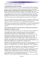
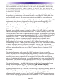
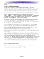
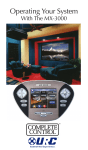
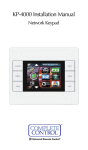
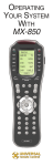
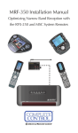
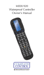
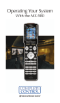
MRZ-260 Installation Manual
MRZ-260 Installation Manual ©2009-2013 Universal Remote
Control, Inc.
The information in this owner’s manual is copyright protected. No part of
this manual may be copied or reproduced in any form without prior written
consent from Universal Remote Control, Inc.
UNIVERSAL REMOTE CONTROL, INC. SHALL NOT BE LIABLE FOR OPERATIONAL, TECHNICAL OR EDITORIAL ERRORS/OMISSIONS MADE IN
THIS MANUAL.
The Home Theater installation on the cover was designed and installed by
Stone-Glidden of King of Prussia and Doylestown, PA.
The information in this owner’s manual may be subject to change without
prior notice.
Complete Control is a registered trademark of Universal Remote Control,
Inc.
All other brand or product names are trademarks or registered trademarks
of their respective companies or organizations.
500 Mamaroneck Avenue, Harrison, NY 10528
Phone: (914) 835-4484 Fax: (914) 835-4532
TABLE OF CONTENTS
Introduction
1
Features and Benefits
2
Parts Guide
2
Installation
3
Testing
5
Front Blaster Overload
7
Disabling the Front Blaster - Step by Step via PC
7
Controlling Four Identical Components/Zones
8
Identical Components/Zones - Step by Step via PC
8
Programming For Multiple Equipment Locations
10
Limited Warranty Statement
11
End User Agreement
13
Frequently Asked Questions
14
Specifications
14
Federal Communication Commission
Interference Statement
15
MRZ-260 BASE STATION
Introduction
The MRZ-260 base station is an “addressable” base station. MAC
addressing gives you the ability to use an unlimited amount of MRZ260’s and allows the control of many identical components as needed
throughout the house. The MRZ-260 is only compatible with 2.4
GHz remote controls (Z remotes) such as the MX-880Z.
1. The MX-880Z sends radio
waves in every direction, so you
don’t have to point the remote
anymore!
2. The MRZ-260 built-in Front Blaster sends commands to components in the same cabinet space or you can use flashers.
3. Self-adhesive “Flashers” affix to
the Infrared sensors on the front panels of your components. The
Flashers relay commands to components out of sight of the MRZ-260
Front Blaster. The flashers plug in to
the MRZ-260 rear flasher line outputs via their 10 foot cables.
Uniquely, the MRZ-260 can also
connect to components with rear
panel IR Inputs via its adjustable IR
Line Outputs.
Page 1
MRZ-260 BASE STATION
Features and Benefits
Interference Rejection and Extended Range via Spread Spectrum
The MRZ-260 receives RF (radio frequency) signals via it’s integrated RF receiver and antenna. A compatible RF remote such as the
MX-880Z can be used with the MRZ-260 base station.
Two Fixed IR Outputs one with RFTX URC Lighting Control
The MRZ-260 is equipped with two fixed IR line outputs with standard
3.5 mm jacks for standard and sleeved IR emitter/flashers. One Fixed
IR Output has a dual role for URC Lighting Control via the RFTX
transmitter
Two Variable IR Outputs Match Rear Panel IR Inputs
The MRZ-260 is equipped with two adjustable IR line outputs. Each
output can be individually matched to rear panel IR inputs on any
component that is designed to be operated by a standard IR repeater.
The outputs utilize a 3.5mm jack and are compatible with standard IR
emitter/flashers as well.
No Limit Equipment Locations With Identical Components
Each MX-880Z remote is “addressable.” They can be programmed to
specifically control components in a particular room by installing an
MRZ-260 base station at each location. In operation it’s simple: when
you select a device located in the Den, the MX-880Z remote only
sends commands to the Den. When you select a device located in
the Family Room, the MX-880Z remote only sends commands to it.
A Single MRZ-260 Can Control an Array of Identical Components
or Individual Zones of a Multi Zone Preamp/Matrix Switcher
Each MRZ-260 has four “addressable” IR Line Outputs. For example,
you can control up to four identical TV’s with one MRZ-260 or route
volume commands for a specific zone to a particular zone IR input on
a multi-zone preamp. If you have more than four identical components or zones, there is no limit on how many MRZ-260s can be
installed to control them (thus allowing an unlimited amount of identical components or individual zones in one house).
Parts Guide
The MRZ-260 RF Base Station includes:
1 - MRZ-260 Base Station
1 - Mounting Plate for wall mounting
the MRZ-260
4 - Screws for wall mounting
1 - 9V-300mA Power Supply
12 - Labels for IR Line Outputs
4 - Visible Flashers with 10 foot plug in
cables including 1 pink sleeved
emitter for the RFTX-1 port
4 - Extra self adhesive pads for
Emitters
1 - Screwdriver for Variable Outputs
Page 2
MRZ-260 BASE STATION
Installation and MAC Address Discovery
1. Unplug the MRZ-260. Test all IR commands and macros line of
sight.
2. Power on all AV components including the TV. Turn on all of the
lights and lower all dimmers to 50%. Power on anything that
may create Interference (particularly devices with high speed
microprocessors or hard drives).
3. Once all commands and macros work in direct line of sight,
connect the MRZ-260 to its DC wall adapter and plug the wall
adapter into a live AC outlet.
4. Open CCP editor to discover the MRZ-260 RF base station.
5. Select Program then Configure Home.
6. Add a MRZ-260 base station and the properties window opens.
7. Plug the MX-880Z remote via USB to the PC.
8. Click on the Discover button to automatically discover the MAC
address of the MRZ-260 base or type in the 8 characters found
on the MAC ID sticker located in the rear.
Note: If you
receive a Not
Connected message simply unplug then replug the USB cable and
try again.
9. Once the MRZ-260 is found, highlight the matching MAC
address and select Apply.
10. Now the MAC address will populate the ACCESS ID field.
11. Press OK to close the window and now the MRZ-260 has been
discovered.
12. Place the MRZ-260 in a location at least 3 feet away from satellite receivers, cable boxes, HDTV tuners, DVRs, PCs or any
Page 3
MRZ-260 BASE STATION
other device with a high speed microprocessor (these generate
broad band Radio Frequency Interference -RFI). Of course, you
should keep in mind that the emitter cables are 10’ long.
13. Observe the Status LED of the MRZ-260.
The red POWER LED indicates that the MRZ-260 is
powered on.
The red STATUS LED flashes when a command is
pressed from the remote.
14. Once you have found a location, test to
see if the range is adequate and that
macro reliability is perfect. Start with
the antenna angle set to 45 degrees and
positioned so that the long side of the
antenna is facing the customer’s favorite
seating position.
45°
15. Now that the location is fixed, connect each of the emitters to
the appropriate IR output and run the cable to the appropriate
component. Do not attach the emitters to the front panel yet!
Utilize the included preprinted labels to identify which emitter
goes to which component. If you’d like to make your own, the
slots for the labels have been sized at 12mm to enable a
Brother P-Touch 12mm label to fit perfectly.
NOTE: TiVo, Replay TV, other DVRs, Satellite Receivers and Cable
Boxes are all extremely sensitive to IR overload or saturation. For
this reason, it is recommended that you always connect the IR
flashers for these types of component to the Variable IR Outputs of
the MRZ-260.
Page 4
MRZ-260 BASE STATION
Testing
Test a few commands for each device before fixing the flasher in
place on the front panel of a device.
Since TiVo, Replay TV, Satellite Receivers and Cable Boxes are all
extremely sensitive to IR overload or saturation, you should test
them thoroughly. Put up the on screen guide and test the navigation
arrows. Compare operation via RF to the original remote control.
Operation should be identical. If operation is inconsistent or
sluggish, lower the IR line output and/or reposition the flasher.
If you still have sluggish operation, check that the remote control is
set to a particular LINE OUT, rather than ALL. When IR commands
are sent to all the flashers in a cabinet, you can have difficulty
adjusting the IR Output. Reprogram the remote control to send IR
commands only via a specific (1-4) Line Output, then readjust the
IR Line Output level.
1. Connect an IR emitter to each IR output and run the emitter
wire to the front panel of each component. DO NOT STICK the
emitter in place. ADJUST the level first.
2. Adjust each of the IR Output levels for best operation. If the
component operates best at minimum level, but is still operating
sluggishly or intermittently, move the emitter farther away from
the components IR sensor.
Page 5
MRZ-260 BASE STATION
Integrating RFTX-1 to control URC Lighting
Not only will you have greater control of your home theatre equipment now, you also have control of your URC Lighting. What better
way to watch a movie and control your universe!
1. Simply plug the included RFTX-1 10’ pink connecting cable into
the MRZ-260 pink fixed port #4.
2. Set the URC Lighting Device in the CCP Editor to RF and set the
IR output to Port #4.
3. Download to the MX-880Z remote, set up your lights and begin
controlling.
Page 6
MRZ-260 BASE STATION
Front Blaster Overload
A few models of audio/video components can be overloaded by the
Front Blaster. If you are having intermittent or inconsistent results
with a particular component, try repositioning the MRZ-260 and
facing the Front Blaster in a different direction. If this improves the
situation but is impractical, it may be necessary to utilize the selfadhesive flashers only and follow the steps below to Disable the
Front Blaster. This will limit the number of components your MRZ260 can control to four. If you have more than four components
you can purchase an additional MRZ-260.
Enabling/Disabling the Front Blaster - Step by
Step via PC
Open the PC software, then plug the MX-880Z PC programmable
remote control into the PC. Open your saved configuration and follow these steps to turn off the front blaster:
1. Open the RF Control Window
The RF Control window opens after selecting RF Control.
2. Turn on/off the Front Blaster
Click on the cell in the IR LED OUTPUT/IR BLASTER column. A list
box will appear. Select a PORT for your device or choose Blaster 1
to enable the front blaster.
3.
Next, click on Save to apply your change.
Page 7
MRZ-260 BASE STATION
Controlling Four Identical Components/Zones
There are several considerations to take into account when you are
installing an MRZ-260 to control an array of identical components:
1. Each identical component must receive IR commands ONLY
from a dedicated Flasher affixed to its front panel or a rear panel
direct IR input. The SIGNAL of the remote should be set to RF
ONLY for each identical component. IR can still be utilized for
other devices in your system!
2. You must note the NUMBER of the Flasher Output you have utilized for EACH of the identical components.
Identical Components/Zones - Step by Step via PC
1. Create and Program a Device for Each Component/Zone
Try to name each device with a descriptive title. At a minimum,
label them TV1, TV2, TV3 and so on.
2. Open the RF Setup Window
The RF Setup window opens after selecting RF Control from the
Program Menu. The RF Setup window is composed of a “spread
sheet” of options for EACH of your devices.
By looking at the Signal column, you can see that the factory
default programming sets all of the devices to send IR commands.
Page 8
MRZ-260 BASE STATION
If you look at the column for IR output, you can see that the default
sends IR commands for all devices to ALL of the IR outputs. Both
options must be changed for identical components.
3. Adjust the Signal For Each of the Identical Devices
The RF Setup window enables you to adjust the Signal output for
each device individually, by clicking on the intersection of a row
and a column and then selecting RF from the two options shown in
the pull down list box.
Select RF from the two options shown for EACH of the identical
TVs. You may leave the other components of the system set to IR
& RF.
4. Adjust the Flashers For Each of the Identical Devices
The RF Setup window enables you to adjust which Flashers output
by the remote control for each device individually, by clicking on
the intersection of a row and a column and then selecting 1-4 from
the five options shown in the pull down list box.
Select the correct Flasher (refer to your connection notes) for
EACH of the identical TVs. You may leave the other components of
the system set to ALL.
See figure on the next page.
In the figure below, each device is set to a specific flasher.
5. Close the RF window and Download to the Remote.
Page 9
MRZ-260 BASE STATION
Programming For Multiple Equipment Locations
You can operate an unlimited amount of different equipment locations within range of your MX-880Z remote, each with an MRZ-260
assigned with a unique MAC Address. You program each of your
remotes to talk to the equipment locations you want by assigning
each of your devices to a receiver. First, you must add and name
your receivers for the locations they are placed in:
1. Open CCP Editor
This editor will allow you to program multiple base stations.
2. Click on Program and Configure Home
3. Add as many MRZ-260 base stations as needed
Follow steps 4 - 11 on page 3 ‘Installation and Discovery’ to automatically discovery multiple base stations for an unlimited amount
of equipment locations.
4. Save and Download to your remote.
Page 10
MRZ-260 BASE STATION
Limited Warranty Statement
1. Limited Warranty and Disclaimers
Universal Remote Control, Inc. (“URC”) warrants that the URC equipment
shall be free from defects in material and workmanship under normal usage
for one (1) year from purchase when such is purchased from URC. This
limited warranty is valid only in the United States of America. URC warrants
that the software will substantially conform in any material respect to its
functional specifications at the time of delivery. URC SHALL NOT BE LIABLE
FOR OPERATIONAL, TECHNICAL OR EDITORIAL ERRORS AND/OR
OMISSIONS MADE IN THE URC DOCUMENTATION. URC DOES NOT
WARRANT THAT THE URC SOFTWARE IS BUG-FREE OR ERROR FREE
OR THAT THERE ARE NO ERRORS/BUGS IN THE URC SOFTWARE.
URC warrants that at the time of purchase the URC equipment and the URC
software complied with all applicable regulations and policies of the Federal
Communications Commissions (“FCC”) regarding electromagnetic
interference caused by electronic/computing devices and to the extent that the
URC equipment and/or the URC software fails to so comply, URC shall, at its
own expense, take all reasonable measures to promptly cause such to
comply.
URC equipment purchases from other than an authorized URC dealer or
distributor are without warranty.
THIS LIMITED WARRANT DOES NOT COVER TECHNICAL ASSISTANCE
FOR HARDWARE OR SOFTWARE USAGE EXCEPT AS EXPRESSLY
PROVIDED FOR HEREIN, THE EQUIPMENT, SOFTWARE AND
DOCUMENTATION OF URC ARE SUPPLIED “AS IS” WITHOUT ANY
WARRANTY, EXPRESS, STATUTORY OR IMPLIED, OF ANY KIND. TO
THE MAXIMUM EXTENT PERMITTED BY APPLICABLE LAW, URC
EXPRESSLY DISCLAIMS ALL WARRANTIES, EXPRESS, STATUTORY OR
IMPLIED, INCLUDING BUT NOT LIMITED TO THE WARRANTIES OF
MERCHANTABILITY AND FITNESS FOR A PARTICULAR PURPOSE. URC
DOES NOT WARRANT, GUARANTEE, OR MAKE ANY
REPRESENTATIONS REGARDING THE USE OF, OR THE RESULTS OF THE
USE OF, THE EQUIPMENT, SOFTWARE OR DOCUMENTATION IN
TERMS OF CORRECTNESS, ACCURACY, RELIABILITY OR OTHERWISE.
EXCEPT AS EXPRESSLY PROVIDED FOR HEREIN, TECHNICAL SERVICES
ARE SUPPLIED “AS IS”, WITHOUT ANY WARRANTY, EXPRESS,
STATUTORY OR IMPLIED, OF ANY KIND. TO THE MAXIMUM EXTENT
PERMITTED BY APPLICABLE LAW, URC EXPRESSLY DISCLAIMS ALL
WARRANTIES, EXPRESS, STATUTORY OR IMPLIED, INCLUDING BUT
NOT LIMITED TO THE WARRANTIES OF QUALITY OR REASONABLE
SKILL AND CARE, OR OUTCOME OR RESULTS.
WITHOUT IN ANY WAY LIMITING THE GENERALITY OF THE OTHER
Page 11
MRZ-260 BASE STATION
PROVISIONS HEREIN, WARRANTY DOES NOT COVER: (I) DAMAGE
FROM MISUSE, NEGLECT OR ACTS OR NATURE, (II) MODIFICATIONS,
(III) INTEGRATION WITH THIRD PARTY CONTENT (IV) BEYOND THE
WARRANTY PERIOD AND/ OR FAILURE TO FOLLOW URC WARRANTY
CLAIM PROCEDURE.
The warranty limitations and warranty disclaimers may not apply to end user
in whole or in part, where such are restricted or excluded by applicable law
and such shall apply to the maximum extent permitted by applicable law.
In the event of any warranty claim, URC will, at its sole option, repair the URC
equipment using new or comparable rebuilt parts, or exchange the URC
equipment for new or rebuilt equipment. In the event of a defect, these are
the end user’s exclusive remedies.
All the URC equipment returned for service, exchange or repair require an
RGA number. To obtain an RGA number, you must complete a Return
Request Form which you may obtain by calling (914) 835-4484 or contacting
URC at [email protected]. To obtain warranty service, end
user must deliver the URC equipment, freight prepaid, in its original packaging
or packaging affording adequate protection to URC at 420 Columbus Avenue,
Valhalla, NY 10595. It is end user’s responsibility to backup any macro
programming, artwork, software or other materials that may have been
programmed into the unit. It is likely that such data, software, or other
materials will be lost during service and URC will not be responsible for any
such damage or loss. A dated purchase receipt, bill of sale, installation contract
or other verifiable proof of purchase is required. For the URC equipment
support and other important information, please visit URC's website available
at www.universalremote.com or call the Customer Service Center at (914)
835-4484.
This limited warranty only covers the URC equipment issues caused by
defects in material or workmanship during ordinary consumer use. It does not
cover product issues caused by any other reason, including but not limited to
product issues due to commercial use, acts of God, third-party installation,
misuse, limitations of technology, or modification of or to any part of the URC
equipment. This limited warranty does not cover the URC equipment sold as
used, as is, refurbished, so called "B stock" or consumables (such as batteries).
This limited warranty is invalid if the factory applied serial number has been
altered or removed from the URC equipment. This limited warranty
specifically excludes the URC equipment sold by unauthorized resellers.
With the exception of URC’s IR-only, broad-based consumer remotes, none of
URC’s PC programmable remotes or any of our Total Control® whole-house
equipment are authorized for online internet sales. Buying URC’s PC
programmable remotes or any of our Total Control® whole-house equipment
online means buying equipment that does not have a URC’s limited warranty.
Page 12
MRZ-260 BASE STATION
Such equipment is not eligible for URC tech support or software support,
either.
2. URC’S Limitations of Liability
IN NO EVENT SHALL URC BE LIABLE FOR INDIRECT, SPECIAL,
INCIDENTAL, EXEMPLARY, PUNITIVE OR CONSEQUENTIAL DAMAGES
OF ANY KIND OR LOSS OF PROFITS OR BUSINESS OPPORTUNITY,
EVEN IF URC IS ADVISED OF THE POSSIBILITY OF SUCH DAMAGES.
IN NO EVENT SHALL URC BE LIABLE FOR LOSS OF OR DAMAGE TO
DATA, COMPUTER SYSTEMS OR COMPUTER PROGRAMS.
URC’S LIABILITY, IF ANY, FOR DIRECT DAMAGES OF ANY FORM SHALL
BE LIMITED TO ACTUAL DAMAGES, NOT IN EXCESS OF AMOUNTS
PAID BY END USER FOR THE URC EQUIPMENT.
IN NO EVENT SHALL URC BE LIABLE FOR ANY EVENTS BEYOND ITS
CONTROL, INCLUDING ANY INSTANCE OF FORCE MAJEURE.
IN NO EVENT SHALL URC BE LIABLE FOR THE ACTS OR OMISSIONS OF
END USER OR ANY THIRD PARTY.
THE LIMITATIONS OF LIABILITY MAY NOT APPLY TO END USER IN
WHOLE OR IN PART, WHERE SUCH ARE RESTRICTED LIMITED OR
EXCLUDED BY APPLICABLE LAW AND SUCH SHALL APPLY TO THE
MAXIMUM EXTENT PERMITTED BY APPLICABLE LAW.
URC SHALL NOT BE HELD RESPONSIBLE FOR THE STATEMENTS MADE
BY OTHERS.
SOME STATES OR JURISDICTIONS DO NOT ALLOW THE EXCLUSION
OR LIMITATION OF INCIDENTAL OR CONSEQUENTIAL DAMAGES, OR
ALLOW LIMITATIONS ON HOW LONG AN IMPLIED WARRANTY
LASTS, SO THE ABOVE LIMITATIONS OR EXCLUSIONS MAY NOT APPLY
TO END USER. THIS LIMITED WARRANTY GIVES END USER SPECIFIC
LEGAL RIGHTS AND END USER MAY HAVE OTHER RIGHTS WHICH
VARY FROM STATE TO STATE OR JURISDICTION TO JURISDICTION.
End User Agreement
The terms and conditions of the End User Agreement available at
www.universalremote.com/eua.php shall apply.
Page 13
MRZ-260 BASE STATION
Frequently Asked Questions
Can I use flasher/emitters that I have already installed in the system to connect to the MRZ-260?
Yes, the flashers are compatible if they use 3.5mm mono mini plugs with
the same polarity (Tip is data, sleeve is ground). It is important to notate
the RFTX-1 shared port utilizes a sleeved emitter for long term use.
I’m getting inconsistent operation regardless of flasher level or
position.
Some components are easily overloaded with IR from nearby flashers.
Prevent IR from affecting the problem component from other flashers or the
front panel blaster by setting the device to a specific IR Line Output instead
of ALL, then adjust the Line Output.
I am unable to control my URC Lighting Dimmer/Switch with the
MRZ-260. Now what?
Make sure the RF switch on the RFTX-1 is set to the correct frequency for
the URC Dimmer or Switch. URC Lighting Models MRFA is 418MHz and
MRFB is 433MHz.
Specifications
Power Supply: 9V 300mA
2 Variable IR Outputs: 3.5mm Mono Mini Jack
2 Fixed IR Outputs (1 combination RFTX-1 Port): 3.5 mm Mono
Mini Jack (Use sleeved emitter only for RFTX-1 output)
RF Frequency: 2.4GHz
Size: 5”x3.25”x1”
Page 14
MRZ-260 BASE STATION
Federal Communication Commission
Interference Statement
This equipment has been tested and found to comply with the limits for a Class B digital device, pursuant to part 15 of the FCC Rules. These limits are designed to provide
reasonable protection against harmful interference in a residential installation. This
equipment generates, uses and can radiate radio frequency energy and, if not installed
and used in accordance with the instructions, may cause harmful interference to radio
communications. However, there is no guarantee that interference will not occur in a
particular installation. If this equipment does cause harmful interference to radio or television reception, which can be determined by turning the equipment off and on, the
user is encouraged to try to correct the interference by one more of the following measures:
u Reorient or relocate the receiving antenna.
u Increase the separation between the equipment and receiver.
u Connect the equipment into an outlet on a circuit different from that to
which the receiver is connected.
u Consult the dealer or an experienced radio/TV technician for help.
Warning!
Changes or modifications not expressly approved by the manufacturer could void the
user's authority to operate the equipment.
Note : The manufacturer is not responsible for any Radio or TV interference caused by
unauthorized modifications to this equipment. Such modifications could void the user's
authority to operate the equipment.
FCC Caution
This device complies with Part 15 of the FCC Rules. Operation is subject to the
following two conditions: (1) this device may not cause harmful interference, and (2) this
device must accept any interference received, including interference that may cause
undesired operation.
Any changes or modifications not expressly approved by the party responsible for compliance could void the authority to operate equipment.
The antenna(s) used for this transmitter must not be co-located or operating in
conjunction with any other antenna or transmitter.
Page 15
500 Mamaroneck Avenue, Harrison, NY 10528
Phone: (914) 835-4484 Fax: (914) 835-4532
www.universalremote.com
OCE-0057G REV02