1
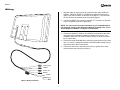
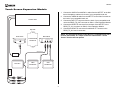
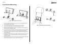
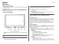
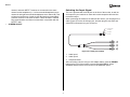
MZ7TFT
Installation and Operation Manual
MZ7TFT
TOUCH PANEL 7-INCH TFT LCD
IR
POWER
AV-IN
Introduction
Thank you for purchasing the Audiovox MZ7TFT Touch Screen Monitor. This
package contains (1) one MZ7TFT, Installation and Operation Manual,
mounting bracket with tool, wiring harness, touch screen expansion module
and a three year limited warranty.
Toll-Free Installation Assistance
If you require assistance, contact Technical Support at 1-800-645-4994 from
9:00 a.m. to 6:00 p.m. EST Monday through Friday (U.S.A. and Canada only).
MZ7TFT
Wiring
1. Align the ridges on either end of the combined input cable (VIDEO IN,
AUDIO L, AUDIO R, REAR TS, GROUND and ACC) and connect the
cable to the male connector on the back of the MZ7TFT. The connector
will only fit when the notched areas are properly aligned.
2. Connect the REAR TS connector to the MZ7-TFT connector on the back
of your compatible head unit (if applicable).
NOTE: You can connect up to three monitors to your compatible head
unit using the Touch Screen Expansion Module (included). See “Touch
Screen Expansion Module” on page 4 for instructions.
3. Connect the AUDIO R, AUDIO L and VIDEO IN connectors to the Video
and Audio output (Headphone Multizone) cables on the back of your
compatible head unit or to another auxiliary device for which you would
like to output video.
4. Connect the black GROUND wire to the factory ground wire on your head
unit, or to a clean, unpainted metal part of the automobile chassis using a
ring terminal and a sheet metal screw.
5. Connect the ACC wire to the factory accessory or ignition wire, which
receives power when the key is turned on.
Red
Yellow
White
Black
FU
SE
AUDIO R (right)
VIDEO IN
AUDIO L (left)
REAR TS
GROUND
ACC
Figure 1: Wiring Connections
3
MZ7TFT
Touch Screen Expansion Module
1. Connect the AUDIO R and AUDIO L cables from the MZ7TFT to the Multizone Headphone cables on the back of your compatible head unit.
2. Connect the VIDEO IN cable from the MZ7TFT to the Video Out cable on
the back of your compatible head unit.
HEAD UNIT
3. Connect the MZ7-TFT connector from the back of your compatible head
unit to the REAR_TS_OUT connector on Side 1 of the Expansion Module.
4. Connect the REAR TS connector from the back of the MZ7TFT to the
REAR_TS_IN 1 connector on Side 2 of the Expansion Module.
5. Connect the REAR TS connectors for additional TFT screens to the
REAR_TS_IN 2 and 3 connectors.
Top View
Side 2 View
Side 1 View
EXPANSION
MODULE
REAR_TS_IN
1
2
3
REAR TS (Black)
REAR TS (Black)
MZ7-TFT
2ND
MONITOR
3RD
MONITOR
Multizone
Headphone
MZ7TFT
REAR TS (Black)
Black
REAR_TS_OUT
NOTE: The touchscreen feature of the MZ7TFT is compatible only with a
receiver with an MZ7-TFT output connector. Otherwise the "Touch
Screen" function will not operate.
Red
White
VIDEO OUT (Yellow)
AUDIO R (Red)
AUDIO L (White)
VIDEO IN (Yellow)
4
MZ7TFT
Installation/Mounting
Figure 2: Attach Bracket/Secure Bracket
1. Insert the metal end of the center arm on the mounting bracket into the
slot on the back of the monitor.
2. Turn the large plastic nut to secure the bracket to the monitor.
Figure 3: Install Headrest/Tighten and Adjust
3. Tighten the smaller plastic nut to further secure the bracket.
4. Install the headrest through the holes in the headrest mounting pieces on
either end of the mounting bracket.
5. Use the Allen wrench provided to loosen the headrest mounting pieces on
either end and rotate, if necessary, to achieve the appropriate depth.
6. Use the Allen wrench provided to secure the headrest mounting pieces to
the headrest poles.
7. Position the monitor at the desired angle, and then use the Allen wrench
to tighten the other side of the headrest mounting pieces and prevent
them from rotating.
8. Once installed, use the knob on the top of the center arm of the mounting
bracket to tilt or rotate the monitor. Tighten when finished.
5
MZ7TFT
Operation
Power On/Off/Standby
NOTE: Your head unit must be compatible with the MZ7TFT touch
screen capability for the IR remote repeater function to work.
The input allows voltage ranges from DC 10.8V to 16V, which includes the DC
12V car power supply.
After connecting the power, the monitor will be in standby mode. Press the
POWER button to turn the monitor on. Press and hold the POWER button to
return the unit to standby mode.
4. Touch Screen
Controls and Indicators
5. Infrared Transmitter Array: Do not block or cover this area, as it will
affect audio transmission to headphones.
3. AV-IN: Audio/video input connector (AUX AV IN).
NOTE: Your head unit must be compatible with the MZ7TFT touch
screen capability for the Touch Screen function to work.
IR Interference
When used in or near direct sunlight, you may experience loud background
noise or a low audio signal. This is inherent in Infrared Ray communication
and does not mean there is a problem with the MZ7TFT itself.
If you use the MZ7TFT by a window with bright sunlight, draw the curtains/
blinds to shut out the direct sunlight, or use the MZ7TFT away from the
sunlight.
Menu Operation
MZ7TFT
While the monitor is turned on, press the POWER button to access the “MAIN
MENU” on the MZ7TFT screen. Touch a main menu selection to see the
corrresponding sub-menu.
• EXIT: To exit the menu from any level, touch the EXIT option on screen.
• PICTURE: Adjust the Brightness, Color, Contrast or Tint from -15 to +15.
• FUNCTION
• BLUE SCREEN (ON/OFF)
• VIDEO IMAGE (NORMAL/IMAGE (MIRROR))
• DISPLAY MODE ( NORMAL/FULL)
• AUTO DIMMER (ON/OFF): Useful for Daytime/Nighttime viewing
• DIMMER SCOPE (-30 to 0), -30 being more dim
• SOURCE
• SOURCE (AV1/AUX AV IN):
• IR AUDIO (A/B/OFF): If there is more than one (1) MZ7TFT in use
simultaneously, each headphone must be set to receive on a different
TOUCH PANEL 7-INCH TFT LCD
IR
POWER
AV-IN
5
2
1
3
5
4
Figure 4: Front Panel Controls
1. POWER: Red illumination indicates standy mode, blue indicates working
state.
NOTE: The LCD backlight will turn off after 10 seconds without signal
input.
2. IR: Remote signal repeater allows you to control your compatible head
unit using the head unit’s remote control.
6
MZ7TFT
•
Selecting the Input Signal
channel, and each MZ7TFT must be set to transmit on the same
channel as the headphone (i.e., left seat monitor/headphones set to
channel A and right seat monitor/headphones set to channel B). This
will prevent interference of audio by the IR signal being transmitted
from two monitors on the same channel. This is inherent in Infrared
Ray communication and does not mean there is a problem with the
MZ7TFT itself.
SCREEN ADJUST
The unit is provided with a AV-IN jack on the front of the monitor, as well as
AV1 inputs for your head unit or other device with composite video and line
level audio output.
When connecting the monitor to an alternate A/V device, you can plug an A/V
cable (Figure 5) into the AV-IN input jack, and then plug the red, white and
yellow RCA connectors into your A/V device.
Composite Video
Audio Return
Audio Right
Audio Left
Red
1
Yellow
2
White
3
Figure 5: A/V Cable (not included)
1. Audio Input 1
2. Audio Input 2
3. Composite Video
After connecting a device using an A/V Adapter Cable, press the POWER
button on the front of the monitor to access the MAIN MENU. Select
SOURCE and then select “AUX AV IN” for the SOURCE option.
7
MZ7TFT
Care and Maintenance
•
•
•
•
•
Do not remove the rear panel of this product. If in need of service, please
call a qualified technician.
Keep away from strong light while using this product so as to obtain the
clearest and the most colorful picture.
Avoid heavy impact, do not drop.
Do not use chemical solutions to clean this unit. Please wipe with a clean
soft cloth to keep brightness of the surface.
Do not expose this product to direct sunlight, heat or humid conditions.
Specifications
Video input: 2 channels CVBS
Audio input: 2 channels stereo
Audio output: Infrared modulation
Monitor specification: 7 inch color TFT LCD
Pixel: RGB 234 x 1440
Power: 10.8~16V, Negative grounding
Max. current: 1A
Standby current: <5mA
Video input amplitude: 1v-pp, 75 ohm load
Audio input amplitude: 2Vrms max
Operating temperature: -10°C~+60°C
IR carrier frequency:
• A Channel: 2.3/2.8MHz±100ppm
• B Channel: 3.2/3.8MHz±100ppm
IR wavelength: 850nm
Modulation mode: Frequency modulation (FM)
Range of IR emitting:
• Frontage: 5m
• Left and right / up and down (30º): 2m
8
Limited Warranty
Audiovox Electronics Corporation (“the Company”) is committed to
quality and customer service, and are pleased to offer you this
Warranty. Please read it thoroughly and contact the Company at 1-800323-4815 with any questions.
Who is covered?
The Company extends this warranty to the original retail purchaser of products
purchased through an authorized Audiovox retailer in the U.S.A., Puerto Rico or
Canada. This warranty is not transferable or assignable. Proof of purchase is
required in the form of an original sales receipt.
What is covered?
The Company warrants that should this product or any part thereof, under normal
use, be proven defective in material or workmanship within 36 months from the
date of original purchase, such defect(s) will be repaired or replaced with a new or
reconditioned product (at the Company's option) without charge for parts and
repair labor.
What is not covered?
This Warranty does not cover the following:
•
Damage incurred during shipping or transporting the product to the
Company or a service center
•
Elimination of car static or motor noise
•
Defects in cosmetic, decorative or non-operative structural parts
•
Correction of antenna problems
•
Costs incurred for installation, removal or reinstallation of the product
•
Consequential damage to compact discs, USB devices, digital media
cards, accessories or vehicle electrical systems
•
Damage caused by improper installation, mishandling, misuse, neglect,
accident, blown fuse, battery leakage, theft or improper storage
•
Products whose factory serial number/bar code label(s) or markings
have been removed or defaced
•
Damage resulting from moisture, humidity, excessive temperature,
extreme environmental conditions or external natural causes
Please review the “Care and Maintenance” section of your Installation
and Operation Manual for additional information regarding the proper
use of your product.
DO NOT RETURN THIS PRODUCT TO THE STORE
Limitations
THE EXTENT OF THE COMPANY'S LIABILITY UNDER THIS WARRANTY
IS LIMITED TO THE REPAIR OR REPLACEMENT PROVIDED ABOVE AND,
IN NO EVENT, SHALL THE COMPANY'S LIABILITY EXCEED THE
PURCHASE PRICE PAID BY PURCHASER FOR THE PRODUCT.
This Warranty is in lieu of all other express warranties or liabilities. ANY IMPLIED
WARRANTIES,
INCLUDING
ANY
IMPLIED
WARRANTY
OF
MERCHANTABILITY, SHALL BE LIMITED TO THE DURATION OF THIS
WRITTEN WARRANTY. ANY ACTION FOR BREACH OF ANY WARRANTY
HEREUNDER
INCLUDING
ANY
IMPLIED
WARRANTY
OF
MERCHANTABILITY MUST BE BROUGHT WITHIN A PERIOD OF 36
MONTHS FROM DATE OF ORIGINAL PURCHASE. IN NO CASE SHALL THE
COMPANY BE LIABLE FOR ANY CONSEQUENTIAL OR INCIDENTAL
DAMAGES FOR BREACH OF THIS OR ANY OTHER WARRANTY, EXPRESS
OR IMPLIED, WHATSOEVER. No person or representative is authorized to
assume for the Company any liability other than expressed herein in connection
with the sale of this product.
Some states do not allow limitations on how long an implied warranty lasts or the
exclusion or limitation of incidental or consequential damage so the above
limitations or exclusions may not apply to you. This Warranty gives you specific
legal rights and you may also have other rights which vary from state to state.
Obtaining Warranty Service
• To obtain repair or replacement within the terms of this Warranty,
call 1-800-323-4815 for the location of a warranty station serving
your area.
• You must prepay the initial shipping charges to the Company.
The Company will pay the return shipping charges for all
warranteed products returned to an address within the U.S.A.,
Puerto Rico or Canada.
• Please package the product securely to avoid shipping damage.
We recommend using a carrier that provides tracking service to
prevent lost packages. Lost or damaged packages are not
covered by this warranty.
• Provide a detailed description of the problem(s) for which you
require service.
Audiovox Electronics Corporation
Hauppauge, NY 11788
Technical Assistance: 1-800-645-4994
www.audiovox.com
© 2008 Audiovox
Ver. 121907
Printed in China