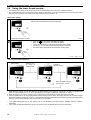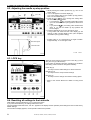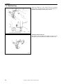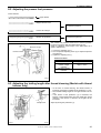
1
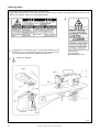
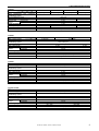
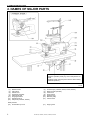
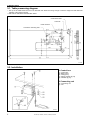
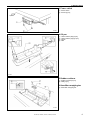
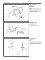
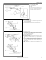
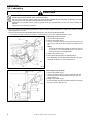
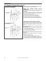
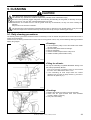
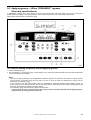
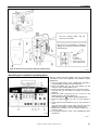
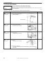
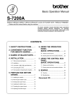
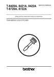
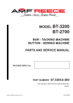
T-8421A
TWIN NEEDLE DIRECT DRIVE LOCK STITCHER
T-8422A
TWIN NEEDLE DIRECT DRIVE LOCK STITCHER
WITH THREAD TRIMMER
T-8452A
TWIN NEEDLE DIRECT DRIVE SPLIT NEEDLE BAR
LOCK STITCHER WITH THREAD TRIMMER
T-8722A
TWIN NEEDLE DIRECT DRIVE LOCK STITCHER
WITH LARGE HOOK AND THREAD TRIMMER
T-8752A
TWIN NEEDLE DIRECT DRIVE SPLIT NEEDLE BAR
LOCK STITCHER WITH LARGE HOOK
AND THREAD TRIMMER
Thank you very much for buying a BROTHER sewing machine. Before using your new machine, please read the safety
instructions below and the explanations given in the instruction manual.
With industrial sewing machines, it is normal to carry out work while positioned directly in front of moving parts such as the
needle and thread take-up, and consequently there is always a danger of injury that can be caused by these parts. Follow
the instructions from training personnel and instructors regarding safe and correct operation before operating the machine so
that you will know how to use it correctly.
SAFETY INSTRUCTIONS
1. Safety indications and their meanings
This instruction manual and the indications and symbols that are used on the machine itself are provided in order to ensure
safe operation of this machine and to prevent accidents and injury to yourself or other people.
Indications
DANGER
The instructions which follow this term indicate situations where failure to follow the
instructions may result in death or serious injury.
CAUTION
The instructions which follow this term indicate situations where failure to follow the
instructions could cause injury when using the machine or physical damage to
equipment and surroundings.
Symbols
·····
This symbol (
) indicates something that you should be careful of. The picture inside the triangle
indicates the nature of the caution that must be taken.
(For example, the symbol at left means “beware of injury”.)
·····
This symbol (
·····
This symbol (
) indicates something that you must do. The picture inside the circle indicates the
nature of the thing that must be done.
(For example, the symbol at left means “you must make the ground connection”.)
) indicates something that you must not do.
T-8421A, 8422A, 8452A, 8722A, 8752A
i
2. Notes on safety
DANGER
Wait at least 5 minutes after turning off the power switch and disconnecting the power cord from the wall outlet
before opening the face plate of the control box. Touching areas where high voltages are present can result in
severe injury.
CAUTION
Environmental requirements
Use the sewing machine in an area which is free
from sources of strong electrical noise such as
electrical line noise or static electric noise.
Sources of strong electrical noise may cause
problems with correct operation.
Any fluctuations in the power supply voltage
should be within ±10% of the rated voltage for the
machine.
Voltage fluctuations which are greater than this
may cause problems with correct operation.
The power supply capacity should be greater than
the requirements for the sewing machine's power
consumption.
Insufficient power supply capacity may cause
problems with correct operation.
The ambient temperature should be within the
range of 5°C to 35°C during use.
Temperatures which are lower or higher than this
may cause problems with correct operation.
The relative humidity should be within the range of
45% to 85% during use, and no dew formation
should occur in any devices.
Excessively dry or humid environments and dew
formation may cause problems with correct
operation.
In the event of an electrical storm, turn off the power
and disconnect the power cord from the wall outlet.
Lightning may cause problems with correct
operation.
Installation
Machine installation should only be carried out by
a qualified technician.
Contact your Brother dealer or a qualified
electrician for any electrical work that may need to
be done.
The sewing machine weighs approximately 50 kg.
The installation should be carried out by two or
more people.
Do not connent the power cord until installation is
complete. The machine may operate if the treadle
is depressed by mistake, which could result in
injury.
Turn off the power switch before inserting or
removing the plug, otherwise damage to the
control box could result.
Be sure to connect the ground. If the ground
connection is not secure, you run a high risk of
receiving a serious electric shock, and problems
with correct operation may also occur.
ii
When securing the cords, do not bend the cords
excessively or fasten them too hard with staples,
otherwise there is the danger that fire or electric
shocks could occur.
If using a work table which has casters, the casters
should be secured in such a way so that they
cannot move.
Use both hands to hold the machine head when
tilting it back or returning it to its original position. If
only one hand is used, the weight of the machine
head may cause your hand to slip, and your hand
may get caught.
Be sure to wear protective goggles and gloves
when handling the lubricating oil and grease, so that
they do not get into your eyes or onto your skin,
otherwise inflammation can result.
Furthermore, do not drink the oil or eat the grease
under any circumstances, as they can cause
vomiting and diarrhea.
Keep the oil out of the reach of children.
T-8421A, 8422A, 8452A, 8722A, 8752A
CAUTION
Sewing
This sewing machine should only be used by
operators who have received the necessary training
in safe use beforehand.
Attach all safety devices before using the sewing
machine. If the machine is used without these
devices attached, injury may result.
The sewing machine should not be used for any
applications other than sewing.
Do not touch any of the moving parts or press any
objects against the machine while sewing, as this
may result in personal injury or damage to the
machine.
Be sure to wear protective goggles when using the
machine.
If goggles are not worn, there is the danger that if a
needle breaks, parts of the broken needle may
enter your eyes and injury may result.
Turn off the power switch at the following times.
The machine may operate if the treadle is
depressed by mistake, which could result in injury.
When threading the needle
When replacing the bobbin and needle
When not using the machine and when leaving
the machine unattended
If using a work table which has casters, the casters
should be secured in such a way so that they
cannot move.
Use both hands to hold the machine head when
tilting it back or returning it to its original position. If
only one hand is used, the weight of the machine
head may cause your hand to slip, and your hand
may get caught.
If an error occurs in machine, or if abnormal noises
or smells are noticed, immediately turn off the
power switch. Then contact your nearest Brother
dealer or a qualified technician.
If the machine develops a problem, contact your
nearest Brother dealer or a qualified technician.
Cleaning
Turn off the power switch before carrying out
cleaning. The machine may operate if the treadle is
depressed by mistake, which could result in injury.
Use both hands to hold the machine head when
tilting it back or returning it to its original position. If
only one hand is used, the weight of the machine
head may cause your hand to slip, and your hand
may get caught.
Be sure to wear protective goggles and gloves
when handling the lubricating oil and grease, so that
they do not get into your eyes or onto your skin,
otherwise inflammation can result.
Furthermore, do not drink the oil or eat the grease
under any circumstances, as they can cause
vomiting and diarrhea.
Keep the oil out of the reach of children.
Use only the proper replacement parts as specified
by Brother.
T-8421A, 8422A, 8452A, 8722A, 8752A
iii
3.Warning labels
The following warning labels appear on the sewing machine.
Please follow the instructions on the labels at all times when using the machine. If the labels have been removed or are
difficult to read, please contact your nearest Brother dealer.
1
2
3
Be sure to connect the ground. If the ground connection is not
secure, you run a high risk of receiving a serious electric shock,
and problems with correct operation may also occur.
4
Direction of operation
Safety devices:
(A) Finger guard
(B) Thread take-up cover
Oil pan
2867M
Control box
2083M
2868M
iv
T-8421A, 8422A, 8452A, 8722A, 8752A
CONTENTS
1. MACHINE SPECIFICATIONS .............. 1
7. SEWING ............................................... 32
2. NAMES OF MAJOR PARTS................ 3
7-1. Sewing............................................................32
7-2. Backtacking ....................................................33
7-3. Sewing condensed stitches ............................34
3. INSTALLATION.................................... 4
3-1. Table processing diagram .............................. 5
3-2. Installation ...................................................... 5
3-3. Lubrication...................................................... 9
3-4. Connecting the cords ..................................... 11
3-4-1. Opening the control box cover ............ 11
3-4-2. Connecting the cords .......................... 11
3-5. Test operation (Operating the treadle) ........... 15
4. PREPARATION BEFORE SEWING .... 16
4-1. Installing the needle .......................................... 16
4-2. Removing the bobbin ..................................... 17
4-3. Winding the lower thread ............................... 18
4-4. Installing the bobbin ....................................... 19
4-5. Threading the upper thread............................ 21
4-6. Adjusting the stitch length .............................. 23
4-7. Using the knee lifter ....................................... 23
4-8. Using the thread wiper
(Models with thread trimmer only) .................. 23
4-9. Corner sewing method (T-8452A, 8752A)...... 24
5. USING THE OPERATION PANEL
(BASIC OPERATIONS)........................ 25
8. THREAD TENSION .............................. 35
8-1. Adjusting the thread tension ...........................35
8-2. Adjusting the presser foot pressure ................36
8-3. Adjusting the trailing length after thread
trimming (Models with thread trimmer only)....36
8-4. Adjusting the thread take-up amount..............37
9. CLEANING ........................................... 38
9-1. Daily cleaning procedures ..............................38
9-2. Lubricating via the oil cover
(every 6 months).............................................39
9-3. Applying grease – When “GREASEUP”
appears (Semi dry specifications)...................40
10. ADJUSTING THE ROTARY HOOK
LUBRICATION AMOUNT .................. 43
11. TROUBLESHOOTING ....................... 44
11-1. Sewing..........................................................44
11-2. Error code displays .......................................49
5-1. Names and functions ..................................... 25
5-2. Sewing start and end backtack stitches ......... 27
5-3. Sewing fixed stitches...................................... 28
5-4. Using the lower thread counter ...................... 29
6. USING THE OPERATION PANEL
(ADVANCED OPERATIONS) .............. 30
6-1. Names and functions ..................................... 30
6-2. Adjusting the needle up stop position............. 31
6-3. LOCK key....................................................... 31
6-4. Resetting all settings to their defaults ............ 31
T-8421A, 8422A, 8452A, 8722A, 8752A
1. MACHINE SPECIFICATIONS
1. MACHINE SPECIFICATIONS
A
A
B
C
D
E
B C
D E
F
Rotary hook
4
Standard hook
7
Large hook
Stitch function
2
Fixed needle bar
5
Split needle bar
Thread trimmer
1
-
2
○
Quick reverse
Thread wiper
4
○
○
T
○
-
Lubrication type
0
Minimum lubrication
3
Semi dry
F
F
1
Use
For foundation
3
For light-weight and
medium- weight materials
T-8421A, 8422A, 8452A, 8722A, 8752A
5
For heavy-weight materials
1. MACHINE SPECIFICATIONS
T-8421A
Max. sewing speed
Start backtacking and continuous
backtacking speed
End backtacking speed
Max. stitch length
Presser foot
Lifting lever
height
Knee lifter
Feed dog height
Needle (DP×5)
Motor
Control circuit
-T3F
3,000 rpm
-T33
3,000 rpm
-T03
4,000 rpm
-T05
3,000 rpm
250–1,800 rpm
1,000 rpm
4 mm
5 mm
7 mm
13 mm
1 mm
#11–#16
AC servo motor (4-pole, 550W)
Microprocessor
#9–#14
#14–#22
T-8422A
Max. sewing speed
Start backtacking and continuous
backtacking speed
End backtacking speed
Max. stitch length
Presser foot
Lifting lever
height
Knee lifter
Feed dog height
Needle (DP×5)
Motor
Control circuit
-403
4,000 rpm
-433
-405
3,000 rpm
250–1,800 rpm
1,000 rpm
4 mm
5 mm
7 mm
13 mm
1 mm
#11–#16
AC servo motor (4-pole, 550W)
Microprocessor
#14–#22
T-8452A
-403
Max. sewing speed
Start backtacking and continuous
backtacking speed
End backtacking speed
Max. stitch length
Presser foot
Lifting lever
height
Knee lifter
Feed dog height
Needle (DP×5)
Motor
Control circuit
-405
3,000 rpm
250–1,800 rpm
1,000 rpm
5 mm
7 mm
13 mm
1 mm
#11–#16
#14–#22
AC servo motor (4-pole, 550W)
Microprocessor
T-8722A, 8752A
-403
Max. sewing speed
Start backtacking and continuous
backtacking speed
End backtacking speed
Max. stitch length
Presser foot
Lifting lever
height
Knee lifter
Feed dog height
Needle (DP×5)
Motor
Control circuit
-405
3,000 rpm
250–1,800 rpm
1,000 rpm
7 mm
7 mm
13 mm
1 mm
#11–#16
#14–#22
AC servo motor (4-pole, 550W)
Microprocessor
T-8421A, 8422A, 8452A, 8722A, 8752A
2
2. NAMES OF MAJOR PARTS
2. NAMES OF MAJOR PARTS
The settings for this sewing machine are carried out
using the operation panel (13), and so this panel is not
used.
(Settings made using this panel will not affect sewing
machine operation.)
2869M
(1)
(3)
(5)
(7)
(9)
(11)
(13)
(15)
Bobbin winder
Lifting lever
Presser foot
Knee lifter assembly
Stitch length dial
Oil gauge window
Operation panel
Stop lever (T-8452A, 8752A )
Safety devices
(16) Thread take-up cover
3
(2)
(4)
(6)
(8)
(10)
(12)
(14)
Thread wiper (T-8422A, 8452A, 8722A, 8752A)
Quick reverse (Actuator)
Control box
Power switch
Reverse lever
Machine pulley
Cotton stand
(17)
Finger guard
T-8421A, 8422A, 8452A, 8722A, 8752A
3. INSTALLATION
3. INSTALLATION
CAUTION
Machine installation should only be carried out by a
qualified technician.
Contact your Brother dealer or a qualified electrician
for any electrical work that may need to be done.
The sewing machine weighs approximately 50 kg.
The installation should be carried out by two or more
people.
Do not connect the power cord until installation is
complete. The machine may operate if the treadle is
depressed by mistake, which could result in injury.
Use both hands to hold the machine head when
tilting it back or returning it to its original position. If
only one hand is used, the weight of the machine
head may cause your hand to slip, and your hand
may get caught.
About the machine set-up location
Do not set up this sewing machine near other equipment such as
televisions, radios or cordless telephones, otherwise such
equipment may be affected by electronic interference from the
sewing machine.
The sewing machine should be plugged directly into an AC wall
outlet. Operation problems may result if extension cords are
used.
2086M
Carrying the machine
The machine should be carried by the arm by two people as
shown in the illustration.
* Hold the motor cover (A) by hand also so that the pulley does
not rotate.
2870M
Tilting back the machine head
Hold section (B) with your foot so that the table does not move,
and then push the arm with both hands to tilt back the machine
head.
2871M
Returning the machine head to the upright position
1. Clear away any tools, etc. which may be near the table holes.
2. While holding the face plate with your left hand, gently return the
machine head to the upright position with your right hand.
2872M
T-8421A, 8422A, 8452A, 8722A, 8752A
4
3. INSTALLATION
3-1. Table processing diagram
The top of the table should be 40 mm in thickness and should be strong enough to hold the weight and with-stand the
vibration of the sewing machine.
Drill holes as indicated in the illustration below.
Cotton stand hole
Cord hole
Head rest hole
Control box mounting hole
2873M
3-2. Installation
1. Control box
(1)
(2)
(3)
(4)
(5)
Control box
Bolts [3 pcs]
Nuts [3 pcs]
Spring washers [3 pcs]
Washers [3 pcs]
2. Connecting rod
(6) Connecting rod
(7) Nut
2091M
5
T-8421A, 8422A, 8452A, 8722A, 8752A
3. INSTALLATION
3. Power switch
(1) Power switch
(2) Screws [2 pcs]
Operator
2092M
4. Oil pan
(1)
(2)
(3)
(4)
Head cushions (left) [2 pcs]
Head cushions (right) [2 pcs]
Oil pan
Oiler
2874M
5. Rubber cushions
(1) Rubber cushions [2 pcs]
(2) Nails [4 pcs]
6. Knee lifter complying bar
(3) Knee lifter complying bar
2875M
T-8421A, 8422A, 8452A, 8722A, 8752A
6
3. INSTALLATION
7. Machine head
(1) Hinges [2 pcs]
(2) Machine head
(3) Head rest
NOTE:
Tap the head rest (3) securely into
the table hole. If the head rest (3) is
not pushed in as far as it will go, the
machine head will not be sufficiently
stable when it is tilted back.
2876M
8. Operation panel
(1) Operation panel
(2) Screws [2 pcs]
(Use for tightening rear cover)
2877M
9. Cotton stand
(1) Cotton stand
NOTE:
Securely tighten the nut (4) so that
the two rubber cushions (2) and the
washer (3) are securely clamped and
so that the cotton stand (1) does not
move.
2878M
7
T-8421A, 8422A, 8452A, 8722A, 8752A
3. INSTALLATION
10. Knee lifter plate
(1) Knee lifter plate
(2) Bolt
* Loosen the bolt (3) and the bolt (4),
and move the knee lifter plate (1) to
a position where it is easy to use.
2879M
<Knee lifter adjustment>
1. Turn the machine pulley so that the feed dog is below the
top of the needle plate.
2. Lower the presser foot (5) by using the lifting lever (4).
2880M
2881M
3. Loosen the nut (6).
4. Turn the screw (8) to adjust so that the amount of play in
the knee lifter (7) is approximately 2 mm when the knee
lifter plate (1) is gently pressed.
5. Securely tighten the nut (6).
6. Loosen the nut (9).
7. Turn the screw (10) until the distance between the end of
the screw (10) and the knee lifter (7) is approximately 5
mm.
8. Turn the adjusting screw (10) to adjust so that the presser
foot (5) is at the desired position within a distance of 13
mm of the needle plate when the knee liter plate (1) is
fully pressed.
9. After adjustment is completed, securely tighten the nut
(9).
Within 13 mm
2882M
T-8421A, 8422A, 8452A, 8722A, 8752A
8
3. INSTALLATION
3-3. Lubrication
CAUTION
Do not connect the power cord until lubrication has been completed, otherwise the machine may operate if the
treadle is depressed by mistake, which could result in injury.
Be sure to wear protective goggles and gloves when handling the lubricating oil and grease, so that they do not get
into your eyes or onto your skin, otherwise inflammation can result.
Furthermore, do not drink the oil or eat the grease under any circumstances, as they can cause vomiting and
diarrhea.
Keep the oil out of the reach of children.
The sewing machine should always be lubricated and the oil supply replenished before it is used for the first time, and also
after long periods of non-use.
Use only the lubricating oil (Nisseki Mitsubishi Sewing Lube 10N; VG10) specified by Brother.
* If this type of lubricating oil is difficult to obtain, the recommended oil to use is <Exxon Mobil Essotex SM10; VG10>.
<Lubricating via the oil cover>
1. Tilt back the machine head.
2. Remove the rubber cap (1).
3. Use the accessory oiler (2) to pour lubricating oil into the
oil cover (3) until the oil level reaches the reference line
(4).
NOTE:
Do not fill with lubricating oil past the reference line (4).
If you pour in too much lubricating oil, it may spill out
when the machine head is tilted back.
4. Replace the rubber cap (1).
5. Return the machine head to its original position.
* If the lubricating oil level drops below the bottom (6) of the
oil gauge window (5), be sure to add more oil.
2883M
<Lubricating via the oil tank>
1. Remove the rubber cap (1).
2. Use the accessory oiler (2) to pour in lubricating oil until
the oil level reaches the top reference line (4) of the oil
gauge window (3).
3. Replace the rubber cap (1).
* If the lubricating oil level drops below the bottom reference
line (6), be sure to add more oil.
2884M
9
T-8421A, 8422A, 8452A, 8722A, 8752A
3. INSTALLATION
■Lubrication
Apply 1 - 2 drops of oil to the places indicated by the arrows.
<Minimum lubrication type only>
* Do not apply oil for semi dry types.
2885M
<T-8452A, 8752A>
<Semi dry type and minimum lubrication type>
Rotary hook race
(left and right)
2886M
2887M
T-8421A, 8422A, 8452A, 8722A, 8752A
10
3. INSTALLATION
3-4. Connecting the cords
DANGER
Wait at least 5 minutes after turning off the power switch and disconnecting the power cord from the wall outlet
before opening the face plate of the control box. Touching areas where high voltages are present can result in
severe injury.
CAUTION
Contact your Brother dealer or a qualified electrician for any electrical work that may need to be done.
Do not connect the power cord until all cords have been connected.
The machine may operate if the treadle is depressed by mistake, which could result in injury.
Be sure to connect the ground. If the ground connection is not secure, you run a high risk of receiving a serious
electric shock, and problems with correct operation may also occur.
3-4-1. Opening the control box cover
(1) Screw
(2) Cover
2888M
3-4-2. Connecting the cords
1. Sewing machine cords
2889M
11
T-8421A, 8422A, 8452A, 8722A, 8752A
3. INSTALLATION
(1)
(2)
(3)
(4)
7-pin head detector unit connector
10-pin operating panel connector
14-pin encoder connector
14-pin machine connector
Refer to the following page for the 4-pin
motor connector.
Push in securely until
the tabs (5) engage.
3131M
3132M
2. Repeat cable tie
(1) Repeat cable tie
(2) Wire clip
<Removal>
NOTE:
Bind the cords in such a way that the
connector does not get pulled out.
All cords that come out from the
control box should be secured to the
cord holder (3) using the repeat
cable tie (1), otherwise vibration from
the sewing machine may cause the
cords to become disconnected,
which can cause problems with the
operation of the control box.
Press
the tab.
<Securing>
Cords
<Closing the cover>
2110M
T-8421A, 8422A, 8452A, 8722A, 8752A
12
3. INSTALLATION
2890M
3. Other cords
(1)
(2)
(3)
(4)
6-pin power supply connector
4-pin motor connector
Wire clip
Power cord
<For single-phase specifications>
Insert the power cord plug (5) into a
wall outlet.
<For three-phase specifications>
1. Attach an appropriate plug to the
power cord (4). (The green and
yellow wire is the ground wire.)
2. Insert
the
plug
into
a
properly-grounded AC power supply.
<Single-phase>
<Three-phase>
NOTE:
Do not use extension cords,
otherwise
machine
operation
problems may result.
Green and yellow wire
(ground wire)
2891M
13
T-8421A, 8422A, 8452A, 8722A, 8752A
3. INSTALLATION
4. Ground wire
(1) Ground wire
(2) Screw [With washer]
(3) Screw
Ground symbol
NOTE:
Always be sure to connect the
ground wire (1), otherwise problems
may occur with sewing machine
operation.
Oil pan
2892M
T-8421A, 8422A, 8452A, 8722A, 8752A
14
3. INSTALLATION
3-5. Test operation (Operating the treadle)
CAUTION
Do not touch any of the moving parts or press any objects against the machine while sewing, as this may result in
personal injury or damage to the machine.
2114M
<Turning on the power>
Press the ON power switch (1).
The power indicator (2) and (3) will illuminate.
NOTE: When turning the power switch on for the first time
The treadle and the operation panel will not operate for
approximately four seconds after the power switch is
turned on.
After approximately 4 seconds, “iniT rPM” (speed
initialization) or “iniT ALL” (full initialization) will be
displayed on the operation panel. After “iniT rPM” or “iniT
ALL” is displayed, the treadle can be operated. (The
operation panel will change to the stitch number display.)
This message will not appear the second and subsequent
times that the power switch is turned on.
2893M
2116M
<Test operation>
1. Check that the machine sews at low speed when the
treadle (4) is gently pressed to position (B).
2. Then check that it sews at high speed when the treadle
(4) is gently pressed to position (C).
3. After pressing the treadle (4) forward, check that the
needle is lowered to the top of the needle plate when the
treadle (4) is returned to the neutral position (A). (when
needle down stopping has been set.)
4. If the treadle (4) is pressed to position (D), (thread
trimming is carried out for models with thread trimmer)
and the needle rises above the needle plate and stops.
2117M
15
T-8421A, 8422A, 8452A, 8722A, 8752A
4. PREPARATION BEFORE SEWING
4. PREPARATION BEFORE SEWING
4-1. Installing the needle
CAUTION
Turn off the power switch before installing the needle.
The machine may operate if the treadle is depressed by mistake, which could result in injury.
1. Turn the machine pulley to move the needle bar to its
highest position.
2. Loosen the screws (1).
3. Insert the needle (2) straight in as far as it will go so that the
long groove is facing inward, and then securely tighten the
screws (1).
<T-8421A, 8422A, 8722A>
Long groove
2894M
<T-8452A, 8752A>
Long groove
3125M
T-8421A, 8422A, 8452A, 8722A, 8752A
16
4. PREPARATION BEFORE SEWING
4-2. Removing the bobbin
CAUTION
Turn off the power switch before removing the bobbin.
The machine may operate if the treadle is depressed by mistake, which could result in injury.
<Latch type>
1. Open the slide plates (1) by moving them to the right and
left.
2. Pull the rotary hook latches (2) upward, and them remove
the bobbins (3).
2895M
<Bobbin case type>
1. Open the slide plates (1) by moving them to the right and
left.
2. Lift up the latch (2) of the rotary hook, and then remove the
bobbin case (3).
3. Remove the bobbin.
2896M
17
T-8421A, 8422A, 8452A, 8722A, 8752A
4. PREPARATION BEFORE SEWING
4-3. Winding the lower thread
CAUTION
Do not touch any of the moving parts or press any objects against the machine while winding the lower thread, as this
may result in personal injury or damage to the machine.
1. Turn on the power switch.
2. Place the bobbin (1) onto the bobbin winder shaft (2).
3. Wind the thread several times around the bobbin (1) in the
direction indicated by the arrow.
* Check that the thread is not loose anywhere along the
thread path.
4. Push the bobbin presser arm (3) toward the bobbin (1).
5. Raise the presser foot with the lifting lever.
6. Depress the treadle. Lower thread winding will then start.
7. Once winding of the lower thread is completed, the bobbin
presser arm (3) will return automatically.
8. After the thread has been wound on, remove the bobbin
and cut the thread with the knife (4).
2897M
* Loosen the screw (5) and move the bobbin presser (6) to
adjust the amount of thread wound onto the bobbin.
NOTE:
The amount of thread wound onto the bobbin should be
a maximum of 80 % of the bobbin capacity.
More thread
Less thread
2123M
2124M
T-8421A, 8422A, 8452A, 8722A, 8752A
18
4. PREPARATION BEFORE SEWING
4-4. Installing the bobbin
CAUTION
Turn off the power switch before installing the bobbin.
The machine may operate if the treadle is depressed by mistake, which could result in injury.
2898M
<Latch type>
1. Insert the bobbin (1) into the rotary hook (2) so that the
winding direction is as shown in the illustration.
2. Return the rotary hook latch (3) to its original position.
3. Turn the machine pulley to rotate the rotary hook (2) until
the tension spring (4) is visible.
4. Pass the thread through slit (5) in the rotary hook and then
pass it under the thread tension spring.
5. Pull out the thread to a length of approximately 50 mm.
6. Close the slide plates.
2899M
2900M
There is an anti-spin spring (6) inside the rotary hook. The
anti-spin spring (6) prevents the bobbin from racing at times
such as during thread trimming.
Use bobbins (1) made of light alloy as specified by
BROTHER.
2901M
19
T-8421A, 8422A, 8452A, 8722A, 8752A
4. PREPARATION BEFORE SEWING
<Bobbin case type>
1. Insert the bobbin (1) into the bobbin case (2) so that the
winding direction is as shown in the illustration.
2. There are three types of cap (2) (<A>, <B> and <C>).
Thread the thread by one of the following methods in
accordance with the shape of the bobbin case (2) being
used.
<A>
<A>
1)
2)
2902M
Pass the thread through slot (3) and under the
thread tension spring (4).
Pass the thread through the thread hole (8) and pull
out about 50 mm.
<B> <C>
1) Pass the thread through slot (3) and under the
thread tension spring (4).
2) Pass the thread through slots (5) and (6), and then
through the spring (7).
3) Pass the thread through the thread hole (8) and pull
out about 50 mm.
<B>
3. Insert the bobbin case (2) into the rotary hook.
4. Push latch (9) of the rotary hook flat.
5. Close the slide plates.
3126M
3127M
<C>
2903M
There is an anti-spin spring (10) inside the rotary hook. The
anti-spin spring (10) prevents the bobbin from racing at
times such as during thread trimming.
Use bobbins (1) made of light alloy as specified by
BROTHER.
2904M
T-8421A, 8422A, 8452A, 8722A, 8752A
20
4. PREPARATION BEFORE SEWING
4-5. Threading the upper thread
CAUTION
Turn off the power switch before threading the upper thread.
The machine may operate if the treadle is depressed by mistake, which could result in injury.
・ Turn the machine pulley and raise the thread take-up (1) before threading the upper thread.
This will make threading easier and it will prevent the thread from coming out at the sewing start.
・ Thread the left-side thread first.
21
T-8421A, 8422A, 8452A, 8722A, 8752A
4. PREPARATION BEFORE SEWING
<For all models except foundation
specifications and T-8452A-405>
Do not pass the
thread through.
<For foundation specifications
Center
and T-8452A-405>
Pass the thread
through.
(Refer to p.37)
If the tension discs are opened as
follows, the thread will become easier
to thread.
<Models with thread trimmer>
Press the tension release plate (2).
<Models without thread trimmer>
Press the tension release plate (2),
or operate the lifting lever or the knee
lifter to raise the presser foot.
The thread can be passed securely
in between the tension discs.
Pass the thread on the inside of the tab (3).
2905M
T-8421A, 8422A, 8452A, 8722A, 8752A
22
4. PREPARATION BEFORE SEWING
4-6. Adjusting the stitch length
1. Unlock the stitch length dial (2) by turning the dial lock lever
(1) to the right until a click is heard.
2. Turn the stitch length dial (2) clockwise or counterclockwise
so that the desired stitch length is at the uppermost position
on the dial.
The larger the number, the longer the stitch length will be.
(The numbers on the dial are for use as a guide. The
length of the finished stitches may vary depending on the
type and thickness of material being sewn. Adjust while
looking at the finished stitches.)
When turning the stitch length dial (2) from a larger
setting to a smaller setting, it will be easier to turn the dial
if the reverse lever (3) is pushed to the halfwaydown
position.
3. Turn the dial lock lever (1) firmly to the left to lock the stitch
length dial (2).
* Check that the stitch length dial (2) does not rotate.
Locked
Unlocked
2906M
4-7. Using the knee lifter
The presser foot (2) can be raised by pressing the knee lifter
plate (1).
2907M
2908M
4-8. Using the thread wiper (Models with thread trimmer only)
2909M
Press the thread wiper switch (1) to the
side.
After thread trimming is carried out, the thread wiper (2) will
pull up the thread.
2209M
2910M
23
T-8421A, 8422A, 8452A, 8722A, 8752A
4. PREPARATION BEFORE SEWING
4-9. Corner sewing method (T-8452A, 8752A)
NOTE:
If using this machine in place of a single-needle machine, remove the needle which is not being used. In such cases, do not
use the procedures given below to stop the unused needle bar from moving, otherwise damage to the machine may result.
4-9-1. To stop the needle bars (right and left)
Operate the stop lever after the needle has penetrated the
material and has stopped moving.
Do not sew at speeds of over 1,000 rpm while one of the
needle bars has been stopped.
<To stop operation of the left needle bar>
Move the stop lever (1) to the “L” position.
Needle
stop
3128M
<To stop operation of the right needle bar>
Move the stop lever (1) to the “R” position.
Needle
stop
3129M
<To resume twin-needle sewing>
Press the push lever (2).
The stop lever (1) will then return to its original position
automatically.
Push
3130M
4-9-2. Number of stitches: quick-reference guide
3131M
Sewing angle 40°
No. of stitches 6
Sewing
angle
No. of
Stitches
2
3
4
5
6
7
8
30°
4.8
4.0
3.7
3.0
40°
50°
60°
4.4
3.5
2.9
2.5
2.2
4.6
3.4
2.7
2.3
2.0
1.7
3.5
2.8
2.2
1.9
1.6
70°
80°
90°
100°
110°
120°
130°
140°
4.6
3.0
2.3
1.8
1.5
3.8
2.5
1.9
1.5
1.3
3.2
2.1
1.6
1.3
2.7
1.8
1.3
2.2
1.5
1.8
1.2
1.5
1.1
<For 1/4” needle width>
Determine the stitch length from the chart above to make beautiful corner stitching.
The number of stitches of the outer needle varies according to the combination of sewing angle and stitch length.
[Example]
For a sewing angle of 40° and a stitch length of 2.9 mm, the number of stitches becomes 6.
T-8421A, 8422A, 8452A, 8722A, 8752A
24
5. USING THE OPERATION PANEL (BASIC OPERATIONS)
5. USING THE OPERATION PANEL
(BASIC OPERATIONS)
5-1. Names and functions
• The operation panel keys cannot be operated while sewing is in progress.
Select the keys and set the number of stitches before starting sewing.
• In the case of keys with indicators, the indicator illuminates when that function is operating, and the indicator switches off
when the key is pressed once more.
Power indicator
2135M
The power indicator illuminates when the power is turned on.
(1) Main display
• In start backtack display, AB illuminates and the number of stitches for A and B are
displayed.
• In end backtack display, CD illuminates and the number of stitches for C and D are
displayed.
• In continuous backtack display, ABCD illuminates and the number of stitches for A, B, C
and D are displayed.
• In fixed stitch display, E or F illuminates and the number of stitches for E or F are
displayed.
2136M
(2)
Setting keys
These keys are used to set the number of backtack stitches for A, B, C and D and the
number of fixed stitches for E and F.
• When the
key is pressed, the setting increases from 0 up to 99.
• When the
key is pressed, the setting decreases from 99 down to 0.
2137M
(3)
2138M
2139M
Start backtack key
When this key is pressed so that the indicator illuminates, the number of start backtack
stitches (0−99) in the A and B stitch number displays is sewn.
2140M
(4)
End backtack key
When this key is pressed so that the indicator illuminates, the number of end backtack
stitches (0−99) in the C and D stitch number displays is sewn. When the treadle is
depressed backward, end backtacking is carried out. (For models with thread trimmer, the
thread is trimmed automatically.)
If the treadle has not yet been depressed backward, the end backtack function can be set
to ON, the number of stitches can be changed and the function can be set back to OFF.
2141M
(5)
25
Continuous backtack key
When this key is pressed so that the indicator illuminates, the number of backtack stitches
(0−99) in the A, B, C and D stitch number displays is sewn continuously. The sewing
machine sews a single cycle of A, B, C and D, and for models with thread trimmer, the
thread is trimmed automatically.
2142M
T-8421A, 8422A, 8452A, 8722A, 8752A
5. USING THE OPERATION PANEL (BASIC OPERATIONS)
(6)
Fixed stitch key
When this key is pressed so that the indicator illuminates, the number of stitches (1−1999)
in the E stitch number display is sewn, and then the sewing machine stops automatically.
2143M
(7)
Name label key
When this key is pressed so that the indicator illuminates, fixed stitch sewing of the number
of stitches (1−1999) in the E and F stitch number displays is carried out repeatedly.
2144M
(8)
Pleat presser sewing key
When this key is pressed so that the indicator illuminates, the number of backtack stitches
(1−1999) in the E stitch number display can be sewn by pressing the actuator.
(9)
Thread trimming key (Models with thread trimmer only)
• This can only be set for use together with the fixed stitch key (6) or the name label key
(7).
• When this key is pressed so that the indicator illuminates, the set number of stitches
(start or end backtack stitches or fixed stitches) are sewn, and then the thread is
trimmed automatically.
2145M
2146M
(10)
AUTO key
• This can only be set for use together with the continuous backtack key (5), the fixed
stitch key (6) or the name label key (7).
• When this key is pressed so that the indicator illuminates, the set number of stitches
(start or end backtack stitches or fixed stitches) are sewn automatically and the thread
is then trimmed (models with thread trimmer only) simply by depressing the treadle
once.
2147M
(11)
Sewing speed control display
This shows the sewing speed when the treadle is depressed to the maximum amount.
• If all bars are illuminated, it indicates that the maximum speed can be set.
• If all bars are switched off, it indicates the minimum speed (220 rpm).
(12)
Sewing speed control keys
These keys let you adjust the sewing speed that is used when the treadle is depressed to
the maximum amount.
The sewing speed can also be adjusted while sewing is in progress.
• When the
key is pressed, the sewing speed becomes faster.
• When the
key is pressed, the sewing speed becomes slower.
2148M
2149M
(13)
2150M
2151M
Thread trimming lock key (Models with thread trimmer only)
• When this key is pressed so that the indicator illuminates, the sewing machine stops in
the needle up position without thread trimming being carried out even if the treadle is
depressed backward.
• If the indicator of the thread trimming key (9) is illuminated, the sewing machine stops in
the needle up position without thread trimming being carried out after the set number of
stitches have been sewn.
2152M
(14)
Half stitch key
When the sewing machine is stopped, the needle bar can be moved up and down by
pressing this key.
2153M
(15)
Lower thread counter display
This shows the lower thread counter value.
The counter is reduced by “1” for every ten stitches sewn.
2154M
(16)
Lower thread counter keys
These keys are used to set the initial value for the lower thread counter. (Refer to p.25.)
(17)
RESET key
2155M
This key is used to return the lower thread counter to its initial value and to cancel warning
conditions. (Refer to p.25.)
2156M
T-8421A, 8422A, 8452A, 8722A, 8752A
26
5. USING THE OPERATION PANEL (BASIC OPERATIONS)
5-2. Sewing start and end backtack stitches
2911M
1
Setting start backtack stitches
Example:
2157M
2
Setting end backtack stitches
Example:
2158M
3
Start backtacking is carried out. After it has finished, normal sewing continues for as long as
the treadle remains depressed.
NOTE:
If the treadle is returned to the neutral position, the sewing machine will continue
operating until the set number of start backtack stitches has been sewn.
2159M
4
End backtacking is carried out. After it has finished, the thread is trimmed automatically
(models with thread trimmer) and the sewing machine stops in the needle up position.
NOTE:
• If the treadle is depressed backward before sewing of the set number of start backtack
stitches is complete, end backtacking will not be carried out.
• For models with thread trimmer, if the indicator of the thread trimming lock key is
illuminated, the sewing machine will stop in the needle up position without thread
trimming being carried out.
2160M
27
T-8421A, 8422A, 8452A, 8722A, 8752A
5. USING THE OPERATION PANEL (BASIC OPERATIONS)
5-3. Sewing fixed stitches
2912M
1
2161M
Example:
From 1 to 1999 stitches can be set.
2
After the set number of stitches in E (fixed stitches) have been sewn, the sewing machine
stops in the needle position that has been set by the needle up/down key (refer to p.26). After
this, normal sewing is carried out if the treadle is depressed.
2159M
3
After the treadle is depressed backward, the thread is trimmed (models with thread trimmer)
and the sewing machine switches to fixed stitch sewing mode.
2160M
<Automatic thread trimming (Models with thread trimmer only)>
Press the thread trimming key to turn on the thread trimming function. When the treadle is
continuously depressed, thread trimming is carried out after the fixed stitches have been sewn.
<Automatic sewing>
When the AUTO key is pressed to turn on the automatic sewing function, the fixed stitches are sewn
simply by depressing the treadle once without needing to depress it continuously.
<Start and end backtack sewing>
• The start backtack key and end backtack key can be pressed to turn on the backtack sewing
function.
• If changing the number of end backtack stitches in C and D, press the fixed stitch key to
temporarily turn off the fixed stitch function before making the change. (The CD display will show
the number of stitches and the setting can then be changed.)
T-8421A, 8422A, 8452A, 8722A, 8752A
28
5. USING THE OPERATION PANEL (BASIC OPERATIONS)
5-4. Using the lower thread counter
The lower thread counter can be used to let you know approximately how much lower thread is remaining.
The value displayed by the lower thread counter display is reduced by 1 from the initial setting value each time the sewing
machine sews 10 stitches, and a warning is given when the counter reaches “-5”.
<Initial value setting>
1
After about 2 seconds, the buzzer will sound and the lower thread counter display
will show the initial value which was set previously.
2166M
(Press for 2 seconds or more)
2
key is pressed, the setting increases.
When the
When the
key is pressed, the setting decreases.
If you hold down the keys, the setting will change more quickly.
If a value of “0” is set, the lower thread counter will not operate.
The initial setting value will be accepted when sewing starts.
2167M
2168M
2169M
<Lower thread counter operation>
(Initial value)
Reduces by 1
for every 10
stitches sewn
Press the
RESET key (2).
Press the RESET key (2)
for 2 seconds or more.
2170M
1. When sewing is carried out, the value shown in the lower thread counter display is reduced by 1 for every 10 stitches sewn.
(After the value reaches zero “0”, a minus sign appears and counting continues to a maximum of “-999”.)
2. When the value is “-5” or less, a warning icon (1) illuminates and an electronic buzzer sounds for 5 seconds.
3. After the treadle returns to the neutral position and the sewing machine stops, the sewing machine will not start up again
even if the treadle is depressed. However, if the treadle is depressed backward, the thread is trimmed (models with thread
trimmer) and the sewing machine stops in the needle up stop position.
If you press the RESET key (2), the warning icon (1) will disappear and sewing will be possible when the treadle is
depressed.
If you press and hold the RESET key (2) for 2 seconds or more, the display will return to the initial value.
29
T-8421A, 8422A, 8452A, 8722A, 8752A
6. USING THE OPERATION PANEL (ADVANCED OPERATIONS)
6. USING THE OPERATION PANEL
(ADVANCED OPERATIONS)
The operations described in this section should only be carried out by a technician.
6-1. Names and functions
These are used for making advanced
operating settings.
They should only be used by a technician.
(18)
2171M
Slow start key
• When this key is pressed so that the slow start icon (19) illuminates, the first two
stitches that are sewn immediately after the treadle is depressed backward are sewn at
700rpm. After this, the sewing speed corresponds to the treadle depression amount.
• If you press this key again while the icon (19) is illuminated, the icon (19) will turn off.
2172M
(20)
Correction key
• When this key is pressed so that the correction icon (21) illuminates, correction sewing
can be carried out.
If the sewing machine is stopped, sewing will be carried out at slow speed (250 rpm)
while the actuator is being pressed.
NOTE:
• If you press the actuator while sewing is in progress, backtack stitches will be
sewn.
• Correction sewing cannot be carried out while the indicator of the pleat presser
sewing key (8) is illuminated.
• If you press this key again while the icon (21) is illuminated, the icon (21) will turn off.
2173M
(22)
Needle up/down key
Use this key to select whether the needle bar stops in the up position or the down position
when the treadle is returned to the neutral position and sewing stops.
• When the needle up icon
(23) is illuminated, the needle bar stops in the up position.
• When the needle down icon
(24) is illuminated, the needle bar stops in the down
position.
2207M
T-8421A, 8422A, 8452A, 8722A, 8752A
2208M
2174M
30
6. USING THE OPERATION PANEL (ADVANCED OPERATIONS)
6-2. Adjusting the needle up stop position
2210M
(–10 – 20)
1. While pressing the needle up/down key (1), turn on the
power switch.
2. “n.0 xx” will appear in the main display (2).
(“xx” is the setting value for the needle up stop position,
and “0” is the default setting.)
3. Press the
or
key (3) to change the setting value
for the needle up stop position.
• If you press the
key, the setting value will increase
up to 20 and the needle up stop position will become
lower.
• If you press the key, the setting value will decrease
down to -10 and the needle up stop position will
become higher.
4. Press the ENTER key (4) for two seconds or more.
A long buzzer will sound and the main display (2) will
change to stitch number display mode. (This completes
the needle up stop position setting.)
* A setting value of “10” corresponds to an angle of rotation
of approximately 10° for the upper shaft.
Becomes higher
Becomes lower
2138M
2913M
2139M
6-3. LOCK key
When the power switch is turned on, the LOCK key (1) turns
ON. (The icon (2) is illuminated.)
In this state, the following three key operations are invalid so
that setting values cannot be changed accidentally.
FUNC key (3)
This key is used to make settings for various functions.
ENTER key (4)
This key is used to accept function settings.
MAX key (5)
This key is used to change the maximum sewing speed.
* Refer to the Service Manual for details on using these
keys.
2212M
6-4. Resetting all settings to their defaults
While holding down the RESET key, turn on the power switch.
If you press the ENTER key, the settings will then be reset.
Once the settings have been reset, “iniT ALL” appears in the display and the operation panel settings are reset to their factory
default settings.
Once the above display appears, normal operation will then be possible.
31
T-8421A, 8422A, 8452A, 8722A, 8752A
7. SEWING
7. SEWING
CAUTION
Attach all safety devices before using the sewing machine. If the machine is used without these devices attached,
injury may result.
Turn off the power switch at the following times.
The machine may operate if the treadle is depressed by mistake, which could result in injury.
When threading the needle
When replacing the bobbin and needle
When not using the machine and when leaving the machine unattended
Do not touch any of the moving parts or press any objects against the machine while sewing, as this may result in
personal injury or damage to the machine.
Use both hands to hold the machine head when tilting it back or returning it to its original position. If only one hand
is used, the weight of the machine head may cause your hand to slip, and your hand may get caught.
7-1. Sewing
2914M
1. While holding the two upper threads with your fingers, turn
the machine pulley by hand toward you until the lower
threads come out onto the feed dog.
2. Pull the lower threads toward you and check that they pull
out smoothly.
Lower
thread
Lower thread
2915M
2114M
3. Press the ON power switch (1).
The power indicator (2) and (3) will illuminate.
4. Use the operating panel to carry out the programming
which is necessary for sewing.
(Refer to the chapter on “5. using the operating panel”.)
5. Depress the treadle to start sewing.
2893M
T-8421A, 8422A, 8452A, 8722A, 8752A
32
7. SEWING
7-2. Backtacking
2916M
When the actuator (1) or the reverse lever (2) is pressed
during sewing, the feed direction will be reversed. When it is
released, the feed direction will return to normal.
2917M
<Actuator rotation function>
The actuator can be rotated 90 degrees as shown in the
illustration. Select the position (A or B) that is easier to use.
2918M
33
T-8421A, 8422A, 8452A, 8722A, 8752A
7. SEWING
7-3. Sewing condensed stitches
If you press the actuator (1) or the reverse lever (2) while
sewing is in progress, you can sew stitches (forward
direction) with small stitch lengths.
Before carrying out sewing, set the stitch length for
condensed stitches as follows.
Sewing direction
Condensed stitches
2919M
2920M
Locked
<Setting>
1. Unlock the stitch length dial (4) by turning the dial lock
lever (3) to the right.
2. Turn the stitch length dial (4) to the stitch length to be
used for condensed stitches.
3. Loosen the screw (5) and lift up the stopper (6) until it
touches the reverse stitching lever plate (7).
4. Tighten the screw (5) to secure the stopper (6).
<Sewing>
1. Return the stitch length dial (4) to the stitch length for
normal sewing.
2. Turn the dial lock lever (3) firmly to the left to lock the
stitch length dial (4).
3. Start sewing.
4. At the position where you would like to start sewing
condensed stitches, press the actuator (1) or the reverse
lever (2).
(Condensed stitches are sewn while the actuator (1) or
reverse lever (2) is being pressed.)
Unlocked
* To stop sewing condense stitches and return to using the
backtack function, lower the stopper (6) so that it does not
touch the reverse stitching lever plate (7).
2921M
T-8421A, 8422A, 8452A, 8722A, 8752A
34
8. THREAD TENSION
8. THREAD TENSION
8-1. Adjusting the thread tension
Good even stitches
Upper thread
Lower thread
0572M
Upper thread tension too weak or
lower thread tension too strong
Increase the upper thread tension.
Decrease the lower thread tension.
Upper thread tension too strong
or lower thread tension too weak
Decrease the upper thread tension.
Increase the lower thread tension.
0573M
0574M
<Latch type>
2922M
<Lower thread tension>
CAUTION
Turn off the power switch before adjusting the
lower thread tension.
The machine may operate if the treadle is
depressed by mistake, which could result in injury.
Turn the adjusting screw (1) to adjust.
Becomes weaker
Becomes stronger
<Bobbin case type>
Becomes stronger
Becomes weaker
2923M
<Upper thread tension>
After the lower thread tension has been adjusted, adjust the
upper thread tension so that a good, even stitch is obtained.
1. Lower the presser foot.
2. Adjust by turning the tension nut (2).
Becomes stronger
Becomes weaker
Becomes weaker
Becomes stronger
2924M
35
T-8421A, 8422A, 8452A, 8722A, 8752A
8. THREAD TENSION
8-2. Adjusting the presser foot pressure
Correct stitches
Upper thread
0894M
0895M
Skipped stitches occur
Increase the pressure.
0896M
0897M
Uneven stitch length
Stitches are puckered
Decrease the pressure.
The presser foot pressure should be as weak as possible,
but strong enough so that the material does not slip.
(Refer to “Adjusting screw height” in the table below as a
guide to adjustment.)
Becomes stronger
1. Loosen the adjusting nut (1).
2. Turn the presser adjusting screw (2) to adjust the presser
foot pressure.
3. Tighten the adjusting nut (1).
Becomes weaker
Reference values
Use
For foundation
For light-weight and
medium- weight
materials
For heavy-weight
materials
Adjusting screw height
Approx. 34mm
Approx. 34mm
Approx. 29mm
2925M
8-3. Adjusting the trailing length after thread trimming (Models with thread
trimmer only)
Longer
At the time of thread trimming, the thread tension is
loosened and tension is applied by the pretension (1) only.
The standard trailing length for the upper thread is 33–37
mm.
If the tension of the pretension (1) is increased, the
lengths of the threads trailing from the needle tips will be
reduced; if the tension is reduced, the lengths will be
increased.
Shorter
Trailing thread
2926M
Adjust by turning the pretension (1).
2927M
T-8421A, 8422A, 8452A, 8722A, 8752A
36
8. THREAD TENSION
8-4. Adjusting the thread take-up amount
<For all models except foundation
specifications and T-8452A-405>
2928M
The thread take-up amount is adjusted by how the thread is
passed through the thread amount adjuster (1).
<Using the
adjuster (1)>
standard
thread
amount
For all models except foundation specifications and
T-8452A-405
Do not pass the thread through the thread amount adjuster
(1). Loosen the screw (2) and slide the thread amount
adjuster (1) to the right-side position.
Do not pass the
thread through.
For foundation specifications and T-8452A-405
Pass the thread through the thread amount adjuster (1).
The standard position of the thread amount adjuster (1) is
when the screw (2) is in the center of the adjustment range.
<Adjusting the thread take-up amount>
When the thread has been passed through the thread
amount adjuster (1), the thread take-up amount becomes
less when the thread amount adjuster (1) is moved to the
right.
<For foundation specifications
and T-8452A-405>
Center
It is better not to pass the thread through the thread
amount adjuster (1):
Pass the thread
through.
・ When sewing heavy materials using a sewing machine
with foundation specifications
・ When the thread take-up amount is not enough, such as
when the stitch length is increased
It is better to pass the thread through the thread amount
adjuster (1):
2929M
37
・ When sewing with slippery threads such as synthetic
yarns
・ When sewing light materials
・ When sewing with a stitch length of 2 mm or less
・ When sewing under any of the above three conditions and
you would like to prevent skipped stitches, thread
tightening problems such as looping, or thread breakages
T-8421A, 8422A, 8452A, 8722A, 8752A
9. CLEANING
9. CLEANING
CAUTION
Turn off the power switch before carrying out cleaning.
The machine may operate if the treadle is depressed by mistake, which could result in injury.
Be sure to wear protective goggles and gloves when handling the lubricating oil and grease, so that they do not get
into your eyes or onto your skin, otherwise inflammation can result.
Furthermore, do not drink the oil or eat the grease under any circumstances, as they can cause vomiting and
diarrhea.
Keep the oil out of the reach of children.
Use both hands to hold the machine head when tilting it back or returning it to its original position. If only one hand
is used, the weight of the machine head may cause your hand to slip, and your hand may get caught.
9-1. Daily cleaning procedures
The following cleaning operations should be carried out each day in order to maintain the performance of this machine and to
ensure a long service life.
Furthermore, if the sewing machine has not been used for a long period of time, carry out the following cleaning procedures
before using it again.
<Cleaning>
1. Turn the machine pulley to move the needle to the needle
up stop position.
2. Open the slide plates at the left and right.
3. Remove the bobbin.
4. Clean the thread scraps from the rotary hook.
5. Install the bobbin (and the bobbin case).
2930M
<Filling the oil tank>
Use only the lubricating oil (Nisseki Mitsubishi Sewing Lube
10N; VG10) specified by Brother.
* If this type of lubricating oil is difficult to obtain, the recommended
oil to use is <Exxon Mobil Essotex SM10; VG10>.
1. If the lubricating oil level drops below the bottom
reference line (2) of the oil gauge window (1), be sure to
add more oil. (Refer to p.9.)
2931M
<Checking>
1. Replace the needle if it is bent or if the tip is broken.
2. Check that the upper threads have been threaded
correctly. (Refer to page 22.)
3. Carry out a test sewing.
2932M
T-8421A, 8422A, 8452A, 8722A, 8752A
38
9. CLEANING
<Draining lubricating oil>
1. If the oiler (1) has filled with oil, unscrew the oiler (1) and
dispose of the oil inside it.
2. Screw the oiler (1) back into the oil pan.
3002M
9-2. Lubricating via the oil cover (every 6 months)
<Minimum lubrication specifications>
Pour lubricating oil into the oil cover (1) about once every six
months.
<Semi dry specifications>
Pour lubricating oil into the oil cover (1) about as often as
grease is applied.
2190M
Use only the lubricating oil (Nisseki Mitsubishi Sewing Lube
10N; VG10) specified by Brother.
* If this type of lubricating oil is difficult to obtain, the recommended
oil to use is <Exxon Mobil Essotex SM10; VG10>.
1. Tilt back the machine head.
2. Pour lubricating oil into the oil cover (1) until the oil level
reaches the reference line (2). (Refer to p.9.)
3. Return the machine head to its normal position.
2933M
39
T-8421A, 8422A, 8452A, 8722A, 8752A
9. CLEANING
9-3. Applying grease --- When “GREASEUP” appears
(Semi dry specifications)
If “GREASEUP" flashes on the main display (1) and a buzzer sounds when the power switch is turned on, it means that
grease needs to be applied. (The sewing machine will not operate at this time, even if the treadle is depressed.)
Apply grease while referring to the following page.
2191M
<To continue sewing temporarily without applying grease>
1. Press the RESET key (2).
2. The main display (1) will change to stitch number display mode, and sewing will be possible when the treadle is depressed.
(The power indicator (3) will flash.)
NOTE
・ If you do not apply grease when the “GREASEUP” notification appears, the notification will continue to appear and the
power indicator (3) will flash each time the power is turned on until you reset the notification by carrying out the
procedure on the following page.
・ If you continue to use the sewing machine after the “GREASEUP” notification appears without applying grease (or
without carrying out the reset procedure), “Err100” will appear after a certain period of time and the sewing machine will
be forcibly prevented from operating for safety reasons.
If this happens, apply grease and carry out the reset procedure.
* If you continue to use the sewing machine after carrying out the reset procedure but without applying grease,
problems with the sewing machine may result.
T-8421A, 8422A, 8452A, 8722A, 8752A
40
9. CLEANING
<Applying grease>
NOTE:
・ Use only the grease <BZL-301 (SA2694-001) in the blue
tube> specified by Brother.
Blue
・ Do not use the BZL-300 (SA2355-001) grease in the
white tube with this sewing machine.
2934M
・ Do not use the BZL-301 (SA2694-001) grease in the blue
tube for any models except for those which are indicated
with “Use only the grease <BZL-301 (SA2694-001)>
specified by Brother”.
Purchase the grease unit (SA2693-001) to use for
applying grease.
1. Using the tube
2935M
2. Applying grease
Follow the procedure below to apply grease to the places indicated by arrows on the next page.
Grease
Insert the tip of the nozzle
(1) all the way into the hole
in the part.
1.
2.
3.
4.
Apply grease without
letting it spill out.
Tighten the screw to push in
the grease.
2936M
Turn the power switch to “OFF”.
Remove the screw (2). (Refer to the next page for greasing locations.)
Apply grease to each of the holes until the grease overflows slightly.
Tighten the screw (2) to push in the grease.
5. Use a cloth to wipe away any excess grease from around the screw
(2).
6. Apply grease to all locations shown on the next page in the same way.
7. Carry out the reset procedure given on the next page.
NOTE:
・ Once the grease tube has been opened, remove the nozzle from the
tube, attach the cap securely and store the tube in a cool dark place.
・ The grease should be used as quickly as possible.
・ When using the grease again, remove any old grease from inside the
nozzle first.
(Store the tube away carefully once the tube has been opened, otherwise the
grease remaining inside the tube may deteriorate, and this may affect its
lubricating performance.)
2937M
41
T-8421A, 8422A, 8452A, 8722A, 8752A
9. CLEANING
2938M
Turn the machine pulley until the
screw (1) can be seen.
Use the tip of a screwdriver or similar to
apply 5-10 mm beads of grease to the slide
block slider (2).
4 places at top,
bottom, left and right
of the slide block (3)
* Pour oil into the oil cover at the same time. (Refer to p.9.)
2939M
<Resetting the cumulative operating time>
2940M
After the grease has been applied, carry out the following
procedure to reset the cumulative time between grease
applications.
1. Turn the power switch to “ON”. “GREASEUP” will flash in
the main display (1) and the buzzer will sound.
2. Press the RESET key (2). The main display (1) will
change to stitch number display mode.
3. Press and hold the LOCK key (3) for 2 seconds or more.
The lock icon (4) will switch off and the lock will be
released.
4. Press the FUNC (Function) key (5). “n.134 xxx” will
appear in green in the main display (1).
(xxx represents the time between grease applications.)
5. Press the rightmost key (6). The “xxx” will change to
“0”.
6. Press and hold the ENTER key (7) for two seconds or
more.
The buzzer will make a long beep, and then the main
display (1) will change to stitch number display mode.
7. Depress the treadle to run the sewing machine for 1
second or more.
8. Turn the power switch to “OFF”. (This completes the reset
procedure.)
2139M
T-8421A, 8422A, 8452A, 8722A, 8752A
42
10. ADJUSTING THE ROTARY HOOK LUBRICATION AMOUNT
10. ADJUSTING THE ROTARY HOOK LUBRICATION
AMOUNT
CAUTION
Be careful not to touch your fingers or the lubrication amount check sheet against moving parts such as the rotary
hook or the feed mechanism when checking the amount of oil supplied to the rotary hook, otherwise injury may
result.
Use the following procedure to check the amount of oil being supplied to the rotary hook when replacing the rotary hook or
when changing the sewing speed.
2941M
More oil
Less oil
2942M
Spattered oil
Too much
Correct
Too little
2943M
43
<Guide to lubrication adjustment>
1. Tilt back the machine head.
2. Turn the oil adjusting screw (1) to adjust the height to
within 9-14 mm.
<Checking the lubrication amount>
1. Turn off the power switch.
2. Remove the thread from all points from the thread take-up
to the needle.
3. Remove the needle and the bobbin.
4. Use the lifting lever to lift the presser foot.
5. Turn on the power switch.
6. Run the machine at the normal sewing speed for
approximately 1 minute without sewing any material
(following the same start/stop pattern as when actually
sewing).
7. Place the lubrication amount check sheet (2) to the left of
the rotary hook (the right side is the right side of the rotary
hook), and hold it in place while running the sewing
machine at the normal sewing speed for approximately 8
seconds. (Any type of paper can be used as the
lubrication amount check sheet (2).)
8. Check the amount of oil which has spattered onto the
sheet.
<Adjusting the lubrication amount>
1. Tilt back the machine head.
2. Turn the adjusting screw (1) to adjust the lubrication
amount.
・ If the rotary hook adjusting screw (1) is turned
counterclockwise, the lubrication amount becomes
greater.
・ If the rotary hook adjusting screw (1) is turned
clockwise, the lubrication amount becomes smaller.
3. Check the lubrication amount again according to the
procedure given in “Checking the lubrication amount”
above.
* Turn the adjusting screw (1) and check the lubrication
amount repeatedly until the lubrication amount is
correct.
4. Check the lubrication amount again after the sewing
machine has been used for approximately two hours.
T-8421A, 8422A, 8452A, 8722A, 8752A
11. TROUBLESHOOTING
11. TROUBLESHOOTING
Please check the following points before calling for repairs or service.
If the following remedies do not fix the problem, turn off the power switch and consult a qualified technician or the place of
purchase.
DANGER
Wait at least 5 minutes after turning off the power switch and disconnecting the power cord from the wall outlet
before opening the face plate of the control box. Touching areas where high voltages are present can result in
severe injury.
CAUTION
Turn off the power switch and disconnect the power cord before carrying out troubleshooting.
The machine may operate if the treadle is depressed by mistake, which could result in injury.
11-1. Sewing
Items with a “*” in the “Page” column should only be checked by a qualified technician.
Problem
1
Possible cause
Upper thread is not tight.
Page
Has the thread been threaded incorrectly?
If the thread is threaded incorrectly, thread it correctly.
Is the upper thread tension or lower thread tension too weak?
Adjust the upper thread tension or lower thread tension.
Is the thread take-up spring operating range too small?
Lower the position of the stopper.
18-22
35
*
Lower thread is not tight.
If using a sewing machine with medium-weight material
specifications, poor thread tightening may occur depending on the
type of material being sewn.
In such cases, replace the presser foot with one that has slots on
the underside, or replace the feed dog with a grooved feed dog.
Grooves
Slot
0574M
2
2944M
0573M
Loops appear in seam.
Is the thread path not smooth enough?
Use a file with a fine grain or sandpaper to polish smooth the
thread path.
Is the bobbin not turning smoothly?
Pull out the lower thread to check that there is no slackness in
the thread tension, or replace the bobbin or bobbin case.
Is the thread take-up amount too large?
Adjust the thread take-up amount.
37
0977M
T-8421A, 8422A, 8452A, 8722A, 8752A
44
11. TROUBLESHOOTING
3 Skipped
stitches
while sewing
occur
2945M
4 Skipped stitches at sewing
start
Thread
unravelling
sewing start
at
Is the needle tip bent? Is the needle tip blunt?
If the needle tip is bent or broken, replace the needle.
Is the needle properly installed?
If it is incorrect, install the needle correctly.
Is the machine properly threaded?
If it is incorrect, thread the thread correctly.
Is the presser foot pressure too weak?
Adjust the presser foot pressure.
Is the needle too thin?
Replace the needle with a needle that is one rank thicker.
Is the presser foot too high?
Adjust the height of the presser foot.
Is the thread take-up spring too weak?
Adjust the tension of the thread take-up spring.
Is the thread take-up amount too large?
Adjust the thread take-up amount.
Is the thread take-up spring tension too strong?
Reduce the tension of the thread take-up spring.
Is the thread take-up spring operating range too large?
Raise the position of the stopper.
Are the trailing lengths of the upper threads too short after thread
trimming?
Adjust the pretension.
Are the threads not being trimmed cleanly?
Sharpen the fixed knives, or replace the fixed and movable
knives if necessary.
Is the needle too wide?
Try using a needle with a count that is one lower than the
current needle.
Is the sewing speed too fast at the sewing start?
Use the slow start feature.
Is the needle up stop position too high?
Adjust the needle up stop position.
Is the lower thread pressed by the plate spring (1) after thread
trimming?
If the lower thread is not
pressed by the plate spring
(1), adjust the installation
position of the movable
knife (2).
Lower thread
2947M
If sewing light or medium-weight materials, is a presser foot with
slots on the underside or grooved feed dog being used?
Use a presser foot without slots.
Use a feed dog without grooves.
Grooves
Slot
2944M
2946M
45
T-8421A, 8422A, 8452A, 8722A, 8752A
16
18-22
36
*
*
37
*
*
36
*
30
31
*
11. TROUBLESHOOTING
Problem
5
Possible cause
Uneven seam
Page
Is the presser foot pressure too weak?
Adjust the presser foot pressure.
Is the feed dog too low?
Adjust the feed dog height.
Is the bobbin scratched?
If the bobbin is damaged, smooth it with an oiled grindstone or
replace it.
36
*
2948M
6
Large degree of puckering
(excess tension)
2949M
7
Material slippage
Is the upper thread tension too strong?
Make the upper thread tension as weak as possible.
Is the lower thread tension too strong?
Make the lower thread tension as weak as possible.
Are the thread take-up spring tensions too strong?
Make the thread take-up spring tension as weak as possible.
Is the thread take-up spring operating range too large?
Move the stopper to as high a position as possible.
Is the presser foot pressure too strong?
Adjust the presser foot pressure.
Is the sewing speed too fast?
Use the sewing speed control keys to gradually reduce the
sewing speed.
Is the thread take-up amount too small?
Adjust the thread take-up amount.
Is the presser foot pressure too strong?
Adjust the presser foot pressure.
35
35
*
*
36
26
37
36
2950M
8
Lower thread is tangled at
the sewing start.
Spinning of bobbin during
thread trimming
Lower
thread
Is the bobbin spinning direction correct when the lower thread is
being pulled?
Set the bobbin so that it turns in the opposite direction to the
rotary hook.
Is there too much thread
wound onto the bobbin?
The
bobbin
winding
amount should not be
more that 80 %.
Is the anti-spin spring attached? (Models with thread trimmer)
Attach the anti-spin spring.
Is the bobbin turning smoothly?
If the bobbin is not turning smoothly, replace the bobbin.
Is a bobbin other that the light-alloy bobbins specified by Brother
being used?
Use only bobbins which are specified by Brother.
19
18
19-20
19-20
2124M
2951M
T-8421A, 8422A, 8452A, 8722A, 8752A
46
11. TROUBLESHOOTING
Problem
9
Possible cause
Upper and lower threads
are breaking.
0471M
10
11
Incorrect thread trimming
Broken needles
Page
Is the needle bent or is the needle tip broken?
Replace the needle if it is bent or broken.
Is the needle properly installed?
If it is incorrect, install the needle correctly.
Is the machine properly threaded?
If it is incorrect, thread the thread correctly.
Is the oil tank filled with lubricating oil?
If the level of lubricating oil is below the bottom reference line,
add more oil.
Is the upper or lower thread tension too weak or too strong?
Adjust the upper thread or lower thread tension.
Is the rotary hook blocked with dust or thread scraps?
Clean the rotary hook.
Is the upper thread may be loose because the thread take-up spring
operating range is too small?
Adjust the position of the stopper.
Is the rotary hook, feed dog or other part damaged?
If they are damaged, smooth them with an oiled grindstone or
replace the damaged parts.
Is the thread path damaged?
If the thread path is damaged, smooth it with sandpaper or
replace the damaged part.
Is the thread take-up amount correct?
Adjust the thread take-up amount.
Is the movable knife damaged or bent?
Replace the movable knife
16
18-22
9
35
38
*
*
*
37
*
Is the material being pushed or pulled with excessive force during
sewing?
Is the needle bent, is the needle tip broken, or is the needle hole
blocked?
Replace the needle.
Does the needle drop into the center of the needle hole in the feed
dog?
Check the needle drop position. If the needle does not drop into
the center of the needle hole in the feed dog, reinstall the feed
dog.
If the needle bar has rotated, rotate the needle bar to the
correct position.
16
*
*
Caution
0469M
12
Machine does not operate
when power is turned on
and treadle is pressed.
It is extremely dangerous to leave any pieces of broken
needle sticking in the material. If the needle breaks, search
for all pieces until the whole of the needle is found again.
Furthermore, we recommend we recommend that through
steps be taken to account for such needles to comply with
product liability regulations.
Is the power supply connector
disconnected from the control
box?
Insert
the
connector
securely.
13
2952M
47
T-8421A, 8422A, 8452A, 8722A, 8752A
11. TROUBLESHOOTING
Problem
13
14
15
Possible cause
Page
Machine does not operate
at high speed.
Is the sewing speed setting or backtack speed setting incorrect?
Use the sewing speed control keys to set the high speed.
Machine
sewing.
Is the fixed stitch key turned on?
Press the fixed stitch key so that the indicator turns off.
Is the power supply voltage too low?
Check the power supply.
(If the power cord is too long or too many appliances are being
run from a single outlet, this may cause voltage drops which will
in turn cause the reset function to activate and stop the
machine, even if the power supply itself is normal.)
stops
during
Nothing appears on the
operation panel display.
Is the power supply connector
disconnected from the control
box?
Insert
the
connector
securely.
Is
the
operation
26
26
*
2952M
13
panel
connector inside the control
box disconnected?
Insert
the
connector
securely.
12*
3154M
16
“GREASEUP” flashes on
the operation panel when
the power is turned on.
This display is to notify you that it is time to apply grease.
Apply grease.
T-8421A, 8422A, 8452A, 8722A, 8752A
40*
48
11. TROUBLESHOOTING
11-2. Error code displays
If an error code appears on the operation panel display
1. Make a note of the error code and then turn off the power.
2. After the operation panel display has turned off, eliminate the cause of the error and then turn
the power back on.
2198M
Items with a “*” in the “Page” column should only be checked by a qualified technician.
Error code
Err
1
(Overvoltage)
Possible cause
Page
Does the power supply voltage match the
control box voltage specifications?
Check the voltage.
*
Voltage rating label
2199M
Err
2
(Overcurrent)
Is the electrical equipment connector inside
the control box disconnected?
Insert the connector securely.
*
3155M
Err
3
(Encoder error)
Is the encoder connector inside the control
box disconnected?
Insert the connector securely.
12*
3156M
Err
(Motor lock)
4
Is the motor connector disconnected from the
control box?
Insert the connector securely.
13
Has the machine locked up?
Turn off the power and then turn the machine pulley by hand and check that it
turns easily.
2953M
49
T-8421A, 8422A, 8452A, 8722A, 8752A
11. TROUBLESHOOTING
Error code
Err
5
(Safety switch
operated)
Possible cause
Is the machine connector inside the control
box disconnected?
Insert the connector securely.
Is the machine head tilted back?
Return the machine head to its normal position.
Err
6
(Voltage drop)
Err
8
(Over time)
Err
13
(Treadle unit
error)
Page
12*
3157M
Was the power turned on while the treadle was still depressed?
Return the treadle to the neutral position, and then turn on the power switch.
This appears on the display when the sewing machine has been operating
continuously for 3 minutes or more.
Turn the power switch off and then back on again, and then operate the
sewing machine normally.
Is the treadle unit connector inside the control
box disconnected?
Insert the connector securely.
*
3158M
Err
21
(Thermistor error)
Is connector CN16 inside the control box
disconnected?
Insert the connector securely.
*
3159M
Err 100
(GrEASEUP)
This appears on the display when the sewing machine has continued to be used for
a certain period after the “GREASEUP” notification appears without the grease
being applied (without the reset procedure being carried out).
Apply grease and then carry out the reset procedure.
Err 101
(diP SW4)
Is DIP switch No.4 inside the control box set
to ON?
Set DIP switch No.4 to OFF.
40*
*
3160M
If an error code that is not listed above appears, contact the place of purchase.
T-8421A, 8422A, 8452A, 8722A, 8752A
50
INSTRUCTION MANUAL
http://www.brother.com/
Printed in Japan
T-8421A, 8422A, 8452A , 8722A, 8752A
SA2698-301
2005.04.B (1)