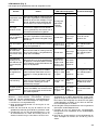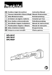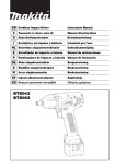
1
GB Cordless Screwdriver
Instruction Manual
F
Visseuse sans fil
Manuel d’instructions
D
Akku-Schrauber
Betriebsanleitung
I
Avvitatrice a batteria
Istruzioni per l’uso
NL Snoerloze schroevendraaier
Gebruiksaanwijzing
E
Atornillador a batería
Manual de instrucciones
P
Aparafusadora a bateria
Manual de instruções
DK Akku skruemaskine
Brugsanvisning
S
Sladdlös momentskruvdragare
Bruksanvisning
N
Akku momentskrutrekker
Bruksanvisning
SF Langaton ruuvinväännin
Käyttöohje
GR Ασύρµατο κατσαβίδι
Οδηγίες χρήσεως
BFT020F
BFT021F
BFT040F
BFT080F
BFT122F
BFT081F
BFT123F
3
2
2
1
1
1
2
4
(C)
E
F
orange
4
E
5
80% - 100%
60% - 80%
40% - 60%
10% - 40%
0% - 10%
F
5
6
80% - 100%
60% - 80%
40% - 60%
10% - 40%
0% - 10%
orange
3
4
A
7
B
8
5
6
10
11
9
7
2
8
13
12 mm (15/32")
10
11
14
15
12
16
9
9 mm (3/8")
10
17
18
11
12
BFT020F
BFT021F
19
360
300
240
20
180
120
60
0
0.5
1
1.5
2
21
13
BFT040F
19
20
14
360
300
240
180
120
60
0
20
21
1
2
3
BFT080F
19
4
360
300
240
180
120
60
0
21
3
4
5
6
7
8
15
3
BFT122F
19
20
360
300
240
180
120
60
05
21
6
7
8
9
10 11 12
16
BFT081F
19
360
300
240
20
180
120
60
21
0
3
4
5
6
7
8
17
BFT123F
19
20
360
300
240
180
120
60
05
22
6
7
8
9
10 11 12
18
19
23
24
20
4
21
ENGLISH
Explanation of general view
1
2
3
4
5
6
7
8
Battery cartridge
Button
Red part
Indicator lamp
Capacity
Switch trigger
Reversing switch lever
Front lamp
9
10
11
12
13
14
15
16
LED indicator
Adjusting ring
Ring
Scale
Adjusting grip
Hole for adjusting grip
Yellow line
Compression spring
17
18
19
20
21
22
23
24
Bit
Sleeve
Range of fastening capacity
Revolution angle (°)
Torque (N•m)
Limit mark
Brush holder cap
Screwdriver
SPECIFICATIONS
Model
Fastening
torque
(N•m)
BFT020F
BFT021F
BFT040F
BFT080F
BFT122F
BFT081F
BFT123F
Hard joint
0.5 – 2
0.5 – 2
1–4
3–8
5 – 12
3–8
5 – 12
Soft joint
0.5 – 2
0.5 – 2
1 – 3.5
3 – 6.5
5 – 10
3 – 7.5
5 – 12
540
320
950
540
320
700
390
No load speed (min-1)
200 x 65 x 251 mm
(with Battery Cartridge BH9020/BH9020A)
200 x 71 x 242 mm
(with Battery Cartridge
BH1220C)
200 x 65 x 274 mm
(with Battery Cartridge BH9033/BH9033A)
200 x 71 x 251 mm
(with Battery Cartridge
BH1233C)
1.3 kg
(with Battery Cartridge BH9020/BH9020A)
1.5 kg
(with Battery Cartridge
BH1220C)
1.5 kg
(with Battery Cartridge BH9033/BH9033A)
1.7 kg
(with Battery Cartridge
BH1233C)
D.C. 9.6 V
D.C. 12 V
Dimensions
Net weight
Rated voltage
• Due to our continuing program of research and development, the specifications herein are subject to change
without notice.
• Note: Specifications may differ from country to country.
5.
Intended use
The tool is intended for screwdriving in wood, metal and
plastic.
IMPORTANT SAFETY INSTRUCTIONS
FOR CHARGER & BATTERY CARTRIDGE
Safety hints
For your own safety, please refer to the enclosed safety
instructions.
SAVE THESE INSTRUCTIONS.
ENC002-3
1.
2.
ADDITIONAL SAFETY RULES FOR TOOL
ENB026-1
1.
2.
3.
4.
Be aware that this tool is always in an operating
condition, because it does not have to be
plugged into an electrical outlet.
Hold tool by insulated gripping surfaces when
performing an operation where the cutting tool
may contact hidden wiring. Contact with a “live”
wire will also make exposed metal parts of the
tool “live” and shock the operator.
Always be sure you have a firm footing. Be sure
no one is below when using the tool in high locations.
Hold the tool firmly.
Keep hands away from rotating parts.
3.
4.
5.
6.
SAVE THESE INSTRUCTIONS — This manual
contains important safety and operating instructions for battery charger.
Before using battery charger, read all instructions and cautionary markings on (1) battery
charger, (2) battery, and (3) product using battery.
CAUTION — To reduce risk of injury, charge only
MAKITA type rechargeable batteries. Other types
of batteries may burst causing personal injury
and damage.
Do not expose charger to rain or snow.
Use of an attachment not recommended or sold
by the battery charger manufacturer may result
in a risk of fire, electric shock, or injury to persons.
To reduce risk of damage to electric plug and
cord, pull by plug rather than cord when disconnecting charger.
5
7.
8.
9.
10.
11.
12.
13.
14.
15.
Make sure cord is located so that it will not be
stepped on, tripped over, or otherwise subjected
to damage or stress.
Do not operate charger with damaged cord or
plug — replace them immediately.
Do not operate charger if it has received a sharp
blow, been dropped, or otherwise damaged in
any way; take it to a qualified serviceman.
Do not disassemble charger or battery cartridge;
take it to a qualified serviceman when service or
repair is required. Incorrect reassembly may
result in a risk of electric shock or fire.
To reduce risk of electric shock, unplug charger
from outlet before attempting any maintenance
or cleaning. Turning off controls will not reduce
this risk.
The battery charger is not intended for use by
young children or infirm persons without supervision.
Young children should be supervised to ensure
that they do not play with the battery charger.
If operating time has become excessively
shorter, stop operating immediately. It may result
in a risk of overheating, possible burns and even
an explosion.
If electrolyte gets into your eyes, rinse them out
with clear water and seek medical attention right
away. It may result in loss of your eyesight.
ADDITIONAL SAFETY RULES FOR CHARGER
& BATTERY CARTRIDGE
1.
2.
3.
4.
5.
6.
7.
8.
6
Do not charge battery cartridge when temperature is BELOW 10°C (50°F) or ABOVE 40°C
(104°F).
Do not attempt to use a step-up transformer, an
engine generator or DC power receptacle.
Do not allow anything to cover or clog the
charger vents.
Do not short the battery cartridge:
(1) Do not touch the terminals with any conductive material.
(2) Avoid storing battery cartridge in a container
with other metal objects such as nails, coins,
etc.
(3) Do not expose battery cartridge to water or
rain.
A battery short can cause a large current flow,
overheating, possible burns and even a breakdown.
Do not store the tool and battery cartridge in
locations where the temperature may reach or
exceed 50°C (122°F).
Do not incinerate the battery cartridge even if it
is severely damaged or is completely worn out.
The battery cartridge can explode in a fire.
Be careful not to drop, shake or strike battery.
Do not charge inside a box or container of any
kind. The battery must be placed in a well ventilated area during charging.
FUNCTIONAL DESCRIPTION
CAUTION:
• Always be sure that the tool is switched off and the battery cartridge is removed before adjusting or checking
function on the tool.
• Always switch off the tool before insertion or removal of
the battery cartridge.
For Models BFT020F, BFT021F, BFT040F, BFT080F
and BFT122F (Fig. 1)
• To remove the battery cartridge, withdraw it from the
tool while pressing the buttons on both sides of the cartridge.
• To insert the battery cartridge, align the tongue on the
battery cartridge with the groove in the housing and slip
it into place. Always insert it all the way until it locks in
place with a little click. If not, it may accidentally fall out
of the tool, causing injury to you or someone around
you.
For Models BFT081F and BFT123F (Fig. 2)
• To remove the battery cartridge, withdraw it from the
tool while sliding the button on the front of the cartridge.
• To insert the battery cartridge, align the tongue on the
battery cartridge with the groove in the housing and slip
it into place. Always insert it all the way until it locks in
place with a little click. If you can see the red part on
the upper side of the button, it is not locked completely.
Insert it fully until the red part cannot be seen. If not, it
may accidentally fall out of the tool, causing injury to
you or someone around you.
• Do not use force when inserting the battery cartridge. If
the cartridge does not slide in easily, it is not being
inserted correctly.
Charging
Before using battery charger, read all instructions and
cautionary markings on the battery charger.
Tips for maintaining maximum battery life
1. Charge the battery cartridge before completely discharged.
Always stop tool operation and charge the battery cartridge when you notice less tool power.
2. Never recharge a fully charged battery cartridge.
Overcharging shortens the battery service life.
3. Charge the battery cartridge with room temperature at
10°C – 40°C (50°F – 104°F).
Let a hot battery cartridge cool down before charging it.
4. Charge the Nickel Metal Hydride battery cartridge
when you do not use it for more than six months.
5. Always stop tool operation and charge the battery cartridge when you notice that the warning lamp lightened up.
6. Remove the battery cartridge from the tool when it
remains unused for a long time in the future.
Refresh charging
Switch action (Fig. 4)
Refreshing adapter (optional accessory) can refresh an
inactive battery cartridge.
• Refresh charging should be done once a week.
• When you charge a new battery cartridge or a battery
cartridge that has not been used for a long time, it may
not accept a full charge. In this case, refresh charging
must be done. The battery cartridge may decrease the
tool performance, because the chemical substance of
the battery cartridge is inactive.
CAUTION:
Before inserting the battery cartridge into the tool, always
check to see that the switch trigger actuates properly and
returns to the “OFF” position when released.
Checking the remaining battery capacity (Fig. 3)
For BH9020A and BH9033A
When charging
When the charging begins, the first (far left) indicating
lamp begins to flicker. Then, as charging proceeds, the
other lamps light, one after the other, to indicate the battery capacity.
When using
When the tool is switched on, the lamps will light after
2 seconds to indicate the remaining battery capacity.
When the tool is switched off, the light goes out.
If the battery has not been used for a long time, or is
needed refresh charging, the orange lamp begins to
flicker.
Use Makita refreshing adapter to refresh the battery.
CAUTION:
A battery cartridge extracted from the charger that has
been unplugged with the battery cartridge inserted does
not indicate the battery capacity due to its protective
function even if the tool is switched on after the battery
insertion into the tool. At this time, recharge it for about
five seconds before use.
NOTE:
Please contact Makita Authorized Service Center if the
warning lamp of the battery cartridge does not light up
when using or charging.
To start the tool, simply pull the switch trigger. Release
the switch trigger to stop.
Reversing switch action (Fig. 5)
CAUTION:
• Always check the direction of rotation before operation.
• Use the reversing switch only after the tool comes to a
complete stop. Changing the direction of rotation
before the tool stops may damage the tool.
• When not operating the tool, always set the reversing
switch lever to the neutral position.
This tool has a reversing switch to change the direction of
rotation. Depress the reversing switch lever from the A
side for clockwise rotation or from the B side for counterclockwise rotation.
When the reversing switch lever is in the neutral position,
the switch trigger cannot be pulled.
Lighting up the lamps (Fig. 6)
CAUTION:
Do not look in the light or see the source of light directly.
Pull the switch trigger to light up the lamp. The lamp
keeps on lighting while the switch trigger is being pulled.
The light automatically goes out 11 seconds after the
switch trigger is released.
NOTE:
Use a dry cloth to wipe the dirt off the lens of lamp. Be
careful not to scratch the lens of lamp, or it may lower the
illumination.
LED indicator (Fig. 7)
The lamp on the tool shows the following functions.
Function
Status
Status of
the LED indicator/beeper
LED indicator
Beeper
Lights up in
green for
approximately
one second.
__
Action to be taken
Auto-stop
fastening
This function works when the tool has
reached the preset fastening torque
and normal tightening has been completed. This helps overtightening to be
avoided.
Delayed re-start
For approximately one second after
auto-stop fastening, the tool does not
start even if the switch trigger is pulled.
Warning against
insufficient fastening
Insufficient fastening has been performed when the switch trigger has
Lights up in
released before reaching the preset fas- red.
tening torque.
A long beep
Retighten the screw.
Warning for battery cartridge
capacity
This indicates the appropriate time to
replace the battery cartridge when the
battery power becomes low.
A series of
long beeps
Replace the battery
with fully charged
one.
Flickers in red
slowly.
__
7
Function
Status
Status of
the LED indicator/beeper
LED indicator
Action to be taken
Beeper
Checking the
remaining battery
capacity,
Autostop
This function works when the battery
power is almost used up. At this time,
tool stops immediately.
Lights up in
red.
A long beep
Check the LED
indicator, light and
beeper operation
This function works to check the proper
operation of the LED indicator, light
and beeper when a battery cartridge
has been inserted into the tool.
Lights up first
in green, next
red. (And then
the light
comes on.)
A series of
very short
beeps
Anti-reset of
controller
This function works when an abnormal
drop of the battery voltage occurs for
some reason and the tool stops.
Flickers in red
and green
alternatively.
A series of
short beeps
Replace the battery
with fully charged
one.
Overheat
This function works when the temperature of the controller goes up very
highly, and the tool stops.
Flickers in red
quickly.
A series of
short beeps
Remove the battery
cartridge immediately and cool the tool
down.
Operation error of
the switch trigger
This function works to avoid the tool's
immediate start upon insertion of battery cartridge into the tool with the
switch trigger being pulled.
Flickers in red
and green
alternatively.
A series of
short beeps
Release the switch
trigger.
Adjusting the fastening torque (Fig. 8 & 9)
When you wish to drive machine screws, wood screws,
hex bolts, etc. with the predetermined torque, adjust the
fastening torque as follows.
1. First remove the battery cartridge from the tool.
2. Loosen and remove the screw that secures ring.
3. Rotate the ring in the front of the tool by hand so that a
hole can be seen below the ring.
4. Place the battery cartridge in place and pull the switch
trigger. Release it so that the adjusting ring rotates
and becomes visible in the hole. And then remove the
battery cartridge.
5. Use an optional adjusting grip to adjust the fastening
torque. Insert the pin of the adjusting grip into the hole
in the front of the tool. And then, turn the adjusting grip
clockwise to set a greater fastening torque, and counterclockwise to set a smaller fastening torque.
6. Align the yellow line with your desired number on the
fastening torque scale.
7. Insert the battery cartridge and be sure that a fastening torque has been set up by using a fastening torque
tester.
8. Rotate the ring in front of the tool and then tighten the
screw to secure the ring.
NOTE:
Numbers on the fastening torque scale is a guideline to
set up your desired fastening torque.
Replace the battery
with fully charged
one.
__
ASSEMBLY
CAUTION:
Always be sure that the tool is switched off and the battery cartridge is removed before carrying out any work on
the tool.
Installing or removing driver bit or socket bit
(Fig. 10 & 11)
Use only the driver bit or socket bit shown in the figure.
Do not use any other driver bit or socket bit.
To install the bit, pull the sleeve in the direction of the
arrow and insert the bit into the sleeve as far as it will go.
Then release the sleeve to secure the bit.
To remove the bit, pull the sleeve in the direction of the
arrow and pull the bit out firmly.
NOTE:
If the bit is not inserted deep enough into the sleeve, the
sleeve will not return to its original position and the bit will
not be secured. In this case, try re-inserting the bit
according to the instructions above.
OPERATION
Screwdriving operation (Fig. 12)
Place the point of the driver bit in the screw head and
apply pressure to the tool. Then switch the tool on. When
the clutch cuts in, the motor will stop automatically. Then
release the switch trigger.
NOTE:
Make sure that the driver bit is inserted straight in the
screw head, or the screw and/or bit may be damaged.
8
Limits of fastening capacity (Fig. 13, 14, 15, 16,
17, 18)
Use the tool within the limits of fastening capacity. If you
use the tool beyond the limits, the clutch does not work.
And the tool cannot deliver enough fastening torque.
NOTE:
• The revolution angle means the angle which a screw/
bolt revolves when the tool attains to 100% from 51% of
desired torque.
• Use of a low temperature conditioned battery cartridge
may sometimes give warning for battery cartridge
capacity by warning lamp and beeper which makes the
tool stop immediately. In this case, the range of fastening capacity may be inferior to those shown in the
above even if a charged battery cartridge is used.
MAINTENANCE
CAUTION:
Always be sure that the tool is switched off and the battery cartridge is removed before attempting to perform
inspection or maintenance.
Replacing carbon brushes
Remove and check the carbon brushes regularly.
Replace when they wear down to the limit mark. Keep
the carbon brushes clean and free to slip in the holders.
Both carbon brushes should be replaced at the same
time. Use only identical carbon brushes. (Fig. 19)
Use a screwdriver to remove the brush holder caps. Take
out the worn carbon brushes, insert the new ones and
secure the brush holder caps. (Fig. 20)
To maintain product SAFETY and RELIABILITY, repairs,
any other maintenance or adjustment should be performed by Makita Authorized, always using Makita
replacement parts.
ACCESSORIES
CAUTION:
These accessories or attachments are recommended for
use with your Makita tool specified in this manual. The
use of any other accessories or attachments might
present a risk of injury to persons. Only use accessory or
attachment for its stated purpose.
If you need any assistance for more details regarding
these accessories, ask your local Makita service center.
•
•
•
•
•
•
Automatic refreshing adapter
Adjust grip
Protector
Grip Base Set
Grip 37
Various type of Makita genuine batteries and chargers
9
NEDERLANDS
Verklaring van algemene gegevens
1
2
3
4
5
6
7
8
9
Accu
Knop
Rood gedeelte
Indicatielampje
Capaciteit
Aan/uit trekschakelaar
Omkeerschakelaar
Voorlamp
LED-indicator
10
11
12
13
14
Instelring
Ring
Schaal
Instelgreep
Bevestigingsgat voor
instelgreep
15 Gele streep
16 Drukveer
17
18
19
20
21
22
23
24
Bit
Mof
Bereik van aandraaicapaciteit
Draaiingshoek (°)
Aandraaikoppel (N•m)
Limietstreep
Borstelhouderdop
Schroevendraaier
TECHNISCHE GEGEVENS
Model
Aandraaikoppel
(N•m)
BFT020F
BFT021F
BFT040F
BFT080F
BFT122F
BFT081F
BFT123F
Harde
verbinding
0,5 – 2
0,5 – 2
1–4
3–8
5 – 12
3–8
5 – 12
Zachte
verbinding
0,5 – 2
0,5 – 2
1 – 3,5
3 – 6,5
5 – 10
3 – 7,5
5 – 12
540
320
950
540
320
700
390
Toerental onbelaste
(min-1)
200 x 65 x 251 mm
(accu inbegrepen BH9020/BH9020A)
200 x 71 x 242 mm
(accu inbegrepen
BH1220C)
200 x 65 x 274 mm
(accu inbegrepen BH9033/BH9033A)
200 x 71 x 251 mm
(accu inbegrepen
BH1233C)
1,3 kg
(accu inbegrepen BH9020/BH9020A)
1,5 kg (accu inbegrepen
BH1220C)
1,5 kg
(accu inbegrepen BH9033/BH9033A)
1,7 kg (accu inbegrepen
BH1233C)
D.C. 9,6 V
D.C. 12 V
Afmetingen
Netto gewicht
Nominale spanning
• In verband met ononderbroken research en ontwikkeling behouden wij ons het recht voor bovenstaande
technische gegevens te wijzigen zonder voorafgaande
kennisgeving.
• Opmerking: De technische gegevens kunnen van land
tot land verschillen.
AANVULLENDE
VEILIGHEIDSVOORSCHRIFTEN
VOOR HET GEREEDSCHAP
Doeleinden van gebruik
Dit gereedschap is bedoeld voor het indraaien van
schroeven in hout, metaal en plastic.
Veiligheidswenken
Voor uw veiligheid dient u de bijgevoegde Veiligheidsvoorschriften nauwkeurig op te volgen.
2.
1.
3.
4.
5.
Denk eraan dat dit gereedschap altijd gebruiksklaar is, omdat het niet op een stopcontact hoeft
te worden aangesloten.
Houd het gereedschap bij de geïsoleerde handgrepen vast wanneer u boort op plaatsen waar
het gereedschap met verborgen elektrische
bedrading in aanraking kan komen. Door contact
met een onder spanning staande draad, zullen
ook de niet-geïsoleerde metalen delen van het
gereedschap onder spanning komen te staan en
zal de gebruiker een elektrische schok krijgen.
Zorg ervoor dat u altijd stevige steun voor de
voeten hebt. Controleer of er zich niemand beneden bevindt wanneer u het gereedschap op een
hoge plaats gaat gebruiken.
Houd het gereedschap stevig vast.
Houd uw handen uit de buurt van roterende
onderdelen.
BEWAAR DEZE VOORSCHRIFTEN.
26
BELANGRIJKE
VEILIGHEIDSVOORSCHRIFTEN VOOR
ACCULADER EN ACCU
AANVULLENDE
VEILIGHEIDSVOORSCHRIFTEN VOOR
ACCULADER EN ACCU
1.
1.
2.
3.
4.
5.
6.
7.
8.
9.
10.
11.
12.
13.
14.
15.
BEWAAR DEZE VOORSCHRIFTEN — Deze
gebruiksaanwijzing bevat belangrijke veiligheids- en bedieningsvoorschriften betreffende
de acculader.
Lees alle voorschriften en waarschuwingen die
zijn aangebracht op (1) de acculader, (2) de accu
en (3) het product waarvoor de accu wordt
gebruikt, aandachtig door alvorens de acculader
in gebruik te nemen.
LET OP — Om gevaar voor verwonding te voorkomen, dient u met de acculader uitsluitend
MAKITA oplaadbare accu’s te laden. Accu’s van
andere merken kunnen gaan barsten en verwondingen of schade veroorzaken.
Stel de acculader niet bloot aan regen of
sneeuw.
Het gebruik van een accessoire dat door de
fabrikant van de acculader niet wordt aanbevolen of verkocht, kan brandgevaar, elektrische
schok of verwondingen veroorzaken.
Om beschadiging van het netsnoer en de stekker
te voorkomen, dient u de stekker vast te pakken
om het netsnoer uit het stopcontact te halen.
Zorg ervoor dat het netsnoer zodanig is
geplaatst, dat niemand erop kan stappen of
erover kan struikelen, en dat het niet aan
beschadiging of druk is blootgesteld.
Gebruik de acculader niet met een beschadigd
netsnoer of een beschadigde stekker — vervang
deze onmiddellijk.
Gebruik de acculader niet indien deze een sterke
schok heeft ondergaan, op de grond is gevallen,
of een andere vorm van beschadiging heeft opgelopen; breng deze naar een bevoegde monteur.
Haal de acculader of de accu niet uit elkaar;
breng deze naar een bevoegde monteur wanneer
onderhoud of reparatie nodig is. Onjuist
opnieuw ineenzetten kan namelijk een elektrische schok of brandgevaar opleveren.
Om gevaar voor een elektrische schok te voorkomen, trekt u de stekker van de acculader uit het
stopcontact alvorens met onderhoud of reinigen
te beginnen. Het gevaar voor een elektrische
schok wordt niet voorkomen door de acculader
alleen maar uit te schakelen.
De acculader is niet bedoeld voor gebruik door
kleine kinderen of geestelijk gestoorden waarop
geen toezicht wordt gehouden.
Houd toezicht op kleine kinderen om te voorkomen dat ze met de acculader spelen.
Wanneer de gebruikstijd van de accu uiterst kort
is geworden, is de accu versleten en moet u het
gebruik ervan onmiddellijk stopzetten. Voortgezet gebruik kan oververhitting van de accu,
brandwonden en zelfs een ontploffing veroorzaken.
Wanneer elektrolyt in uw ogen is terechtgekomen, moet u uw ogen spoelen met schoon water
en onmiddellijk de hulp van een dokter inroepen.
Elektrolyt in de ogen kan blindheid veroorzaken.
2.
3.
4.
5.
6.
7.
8.
Laad de accu niet op bij een temperatuur BENEDEN 10°C of BOVEN 40°C.
Gebruik voor het opladen nooit een verhogingstransformator, een dynamo of een
gelijkstroombron.
Zorg ervoor dat de ventilatiegaten van de acculader niet afgesloten worden of verstopt raken.
Voorkom kortsluiting van de accu:
(1) Raak de accuklemmen nooit aan met een
geleidend materiaal.
(2) Bewaar de accu niet in een bak waarin ook
andere metalen voorwerpen zoals spijkers,
munten e.d. worden bewaard.
(3) Stel de accu niet bloot aan water of regen.
Kortsluiting van de accu kan oorzaak zijn van
een grote stroomafgifte, oververhitting, brandwonden en zelfs defecten.
Bewaar het gereedschap en de accu niet op
plaatsen waar de temperatuur kan oplopen tot
50°C of hoger.
Werp de accu nooit in het vuur, zelfs niet wanneer
deze zwaar beschadigd of volledig versleten is.
De accu kan namelijk ontploffen in het vuur.
Wees voorzichtig dat u de accu niet laat vallen
en hem niet aan schokken of stoten blootstelt.
Laad de accu niet op in een bak of container.
Laad hem uitsluitend op in een goed geventileerde ruimte.
BESCHRIJVING VAN DE FUNCTIES
LET OP:
• Zorg altijd dat het gereedschap is uitgeschakeld en de
accu ervan is verwijderd alvorens de functies op het
gereedschap af te stellen of te controleren.
• Schakel het gereedschap altijd uit alvorens de accu te
installeren of te verwijderen.
Voor de modellen BFT020F, BFT021F, BFT040F,
BFT080F en BFT122F (Fig. 1)
• Om de accu te verwijderen, haalt u deze uit het gereedschap terwijl u de knoppen aan beide zijden van de
accu indrukt.
• Om de accu te installeren, doet u de tong op de accu
overeenkomen met de groef in het huis van het gereedschap, en dan schuift u de accu erin. Schuif de accu zo
ver mogelijk erin totdat deze op zijn plaats vastklikt. Als
u dit niet doet, kan de accu per ongeluk eruit vallen en
uzelf of andere personen in uw omgeving verwonden.
Voor de modellen BFT081F en BFT123F (Fig. 2)
• Om de accu te verwijderen, haalt u deze uit het gereedschap terwijl u de knop op de voorkant van de accu
verschuift.
• Om de accu te installeren, doet u de tong op de accu
overeenkomen met de groef in het huis van het gereedschap, en dan schuift u de accu erin. Schuif de accu zo
ver mogelijk erin totdat deze op zijn plaats vastklikt. Als
het rode gedeelte op de bovenkant van de knop nog
zichtbaar is, zit de accu niet volledig erin. Schuif hem
volledig erin totdat het rode gedeelte niet meer zichtbaar is. Als u dit niet doet, kan de accu per ongeluk
eruit vallen en uzelf of andere personen in uw omgeving verwonden.
27
• Als de accu moeilijk in de houder gaat, moet u niet proberen om hem met geweld erin te duwen. Als de accu
er niet gemakkelijk ingaat, betekent dit dat u hem niet
op de juiste wijze erin steekt.
Laden
Lees alle instructies en waarschuwingen op de acculader
alvorens hem te gebruiken.
Tips om een maximale levensduur van de accu te
verzekeren
1. Laad de accu op voordat hij volledig ontladen is.
Stop het gebruik van het gereedschap en laad de
accu op telkens wanneer u vaststelt dat het vermogen
van het gereedschap verminderd is.
2. Laad een volledig opgeladen accu nooit opnieuw op.
Als u de accu te veel oplaadt, zal deze minder lang
meegaan.
3. Laad de accu op bij een kamertemperatuur tussen
10°C en 40°C.
Laat een warme accu afkoelen alvorens hem op te
laden.
4. Laad de nikkel-metaalhydride accu op wanneer u
deze langer dan zes maanden niet gebruikt.
5. Stop het gebruik van het gereedschap en laad de
accu op telkens wanneer u vaststelt dat het waarschuwingslampje brandt.
6. Verwijder de accu van het gereedschap wanneer u het
gereedschap voor langere tijd niet gaat gebruiken.
De accu opfrissen
Gebruik de opfrisadapter (los verkrijgbaar accessoire)
om een inactieve accu op te frissen.
• De accu dient eens per week te worden opgefrist.
• Een nieuwe accu of een accu die gedurende lange tijd
niet werd gebruikt, kan soms niet volledig worden
opgeladen. In dat geval dient de accu te worden opgefrist. Als u dit niet doet, kan de accu de prestaties van
het gereedschap nadelig beïnvloeden omdat de chemische stof van de accu inactief is.
Controleren van de resterende accucapaciteit
(Fig. 3)
Voor BH9020A en BH9033A
Tijdens het laden
Wanneer het laden begint, zal het eerste indicatielampje
(uiterst links) beginnen te knipperen. Naarmate het laden
wordt voortgezet, zullen de andere lampjes in volgorde
gaan branden om de accucapaciteit aan te geven.
Tijdens het gebruik
Wanneer u het gereedschap inschakelt, gaan de lampjes
na 2 seconden branden om de resterende accucapaciteit
aan te geven. Wanneer u het gereedschap uitschakelt,
zullen de lampjes uitgaan.
Als de accu een lange tijd niet is gebruikt of opgefrist
moet worden, beginnen de oranje lampjes te flikkeren.
Gebruik een Makita opfrisadapter om de accu op te frissen.
28
LET OP:
Als de accu uit de acculader wordt gehaald nadat de
stekker van de acculader uit het stopcontact werd
getrokken terwijl de accu er nog in zat, zal de accu de
acculading niet aangeven als gevolg van een beveiligingsfunctie, zelfs niet nadat de accu in het gereedschap
is geplaatst en het gereedschap is ingeschakeld. Als dit
is gebeurd, laadt u de accu nogmaals gedurende ongeveer vijf seconden op voordat u deze gebruikt.
OPMERKING:
Neem contact op met een erkend Makita servicecentrum
indien het waarschuwingslampje van de accu niet brandt
tijdens het gebruik of tijdens het laden.
Werking van de trekschakelaar (Fig. 4)
LET OP:
Alvorens de accu in het gereedschap te plaatsen, moet u
altijd controleren of de trekschakelaar juist werkt en bij
het loslaten naar de “OFF” positie terugkeert.
Om het gereedschap te starten drukt u gewoon de trekschakelaar in. Laat de trekschakelaar los om het gereedschap te stoppen.
Werking van de omkeerschakelaar (Fig. 5)
LET OP:
• Controleer altijd de draairichting alvorens het gereedschap te gebruiken.
• Verander de stand van de omkeerschakelaar alleen
nadat het gereedschap volledig tot stilstand is gekomen. Indien u de draairichting verandert terwijl de
schroefbit nog draait, kan het gereedschap beschadigd
raken.
• Zet de omkeerschakelaar altijd in de neutrale stand
wanneer het gereedschap niet wordt gebruikt.
Dit gereedschap heeft een omkeerschakelaar voor het
veranderen van de draairichting. Druk de omkeerschakelaar in vanaf zijde A voor rechtse draairichting, en vanaf
zijde B voor linkse draairichting.
Wanneer de omkeerschakelaar in de neutrale stand
staat, kan de trekschakelaar niet worden ingedrukt.
Aanzetten van de lamp (Fig. 6)
LET OP:
Kijk niet direct in het licht van de lamp.
Druk de trekschakelaar in om de lamp aan te zetten. De
lamp blijft branden zolang als u de trekschakelaar ingedrukt houdt. De lamp gaat automatisch uit 11 seconden
na het loslaten van de trekschakelaar.
OPMERKING:
Gebruik een droge doek om vuil op de lamplens eraf te
vegen. Pas op dat u geen krassen maakt op de lamplens,
omdat de verlichtingssterkte daardoor kan verminderen.
LED-indicator (Fig. 7)
Het lampje op het gereedschap toont de volgende functies.
Functie
Status van
LED-indicator/pieptoon
Status
LED-indicator
Te nemen maatregel
Pieptoon
Automatisch stoppen met aandraaien
Deze functie treedt in werking wanneer
het vooraf ingestelde aandraaikoppel is
bereikt en de schroef volledig is aangedraaid. Hierdoor wordt voorkomen dat
de schroef te vast wordt aangedraaid.
Vertraagd
opnieuw starten
Gedurende ongeveer 1 seconde na het
automatisch stoppen met aandraaien,
zal het gereedschap niet starten ook al
wordt de trekschakelaar ingedrukt.
Waarschuwing
voor onvoldoende
aandraaien
Als u de trekschakelaar loslaat voordat
het vooraf ingestelde aandraaikoppel is
Brandt rood.
bereikt, zal de schroef niet goed aangedraaid zijn.
Een lange
pieptoon
Draai de schroef
opnieuw aan.
Waarschuwing
voor accucapaciteit
Toont de geschikte tijd voor het vervanKnippert langgen van de accu wanneer de accuspanzaam in rood.
ning zwak geworden is.
Een reeks
lange pieptonen
Vervang de accu door
een volledig opgeladen accu.
Controleren van
de resterende
accuspanning en
automatisch stoppen
Deze functie treedt in werking wanneer
de accu bijna leeg is. Het gereedschap
stopt dan onmiddellijk.
Brandt rood.
Een lange
pieptoon
Vervang de accu door
een volledig opgeladen accu.
Controleert de
werking van de
LED-indicator, de
lamp en de pieptoon.
Wanneer een accu in het gereedschap
is geplaatst, controleert deze functie de
juiste werking van de LED-indicator, de
lamp en de pieptoon.
Brandt eerst
groen en vervolgens rood.
(Daarna gaat
de lamp aan.)
Een reeks
zeer korte
pieptonen
__
Neutraliseren van
het regelmechanisme
Wanneer een abnormale verlaging van
de accuspanning om een of andere
reden optreedt, treedt deze functie in
werking en zal het gereedschap stoppen.
Knippert beurtelings in rood
en groen.
Een reeks
korte
pieptonen
Vervang de accu door
een volledig opgeladen accu.
Oververhitting
Wanneer de temperatuur van het regelmechanisme zeer hoog wordt, treedt
Knippert snel
deze functie in werking en zal het
in rood.
gereedschap stoppen.
Een reeks
korte
pieptonen
Haal de accu onmiddellijk eruit en laat het
gereedschap afkoelen.
Foutieve werking
van de trekschakelaar
Deze functie voorkomt dat het gereedschap onmiddellijk start wanneer u een
accu erin plaatst terwijl de trekschakelaar wordt ingedrukt.
Een reeks
korte
pieptonen
Laat de trekschakelaar los.
Instellen van het aandraaikoppel (Fig. 8 en 9)
Wanneer u kolomschroeven, houtschroeven, zeskante
bouten e.d. met een gespecificeerd aandraaikoppel wilt
aandraaien, moet u het aandraaikoppel als volgt instellen.
1. Haal de accu uit het gereedschap.
2. Maak de bevestigingsschroef van de ring los en verwijder de schroef.
3. Draai met de hand de ring op de voorkant van het
gereedschap zodat het gat onder de ring zichtbaar wordt.
4. Installeer de accu en druk de trekschakelaar in. Laat
de trekschakelaar los zodat de instelring draait en
zichtbaar wordt in het gat. Haal daarna de accu eruit.
Brandt groen
gedurende
ongeveer
1 seconde.
Knippert beurtelings in rood
en groen.
__
__
5. Gebruik de los verkrijgbare instelgreep om het aandraaikoppel in te stellen. Steek de pen van de instelgreep in het gat op de voorkant van het gereedschap.
Draai daarna de instelgreep naar rechts om een groter
aandraaikoppel in te stellen, of naar links om een kleiner aandraaikoppel in te stellen.
6. Doe de gele streep overeenkomen met het gewenste
cijfer op de aandraaikoppelschaal.
7. Installeer de accu en gebruik een aandraaikoppeltestapparaat om te controleren of het aandraaikoppel
is ingesteld.
8. Draai de ring op de voorkant van het gereedschap en
draai vervolgens de schroef aan om de ring vast te
zetten.
29
OPMERKING:
De cijfers op de aandraaikoppelschaal dienen als een leidraad voor het instellen van het gewenste aandraaikoppel.
INEENZETTEN
LET OP:
Zorg altijd dat het gereedschap is uitgeschakeld en de
accu ervan is verwijderd alvorens enig werk aan het
gereedschap uit te voeren.
Installeren of verwijderen van de schroefbit of
sokbit (Fig. 10 en 11)
Gebruik uitsluitend de afgebeelde schroefbit of sokbit.
Gebruik nooit andere schroefbits of sokbits.
Om de bit te installeren, trekt u de mof in de richting van
de pijl en dan steekt u de bit zo ver mogelijk in de mof.
Laat daarna de mof los om de bit vast te zetten.
Om de bit te verwijderen, trekt u de mof in de richting van
de pijl en dan trekt u de bit krachtig eruit.
OPMERKING:
Als de bit niet diep genoeg in de mof zit, zal de mof niet
naar zijn oorspronkelijke positie terugkeren zodat de bit
niet goed vast zal zitten. Probeer in zo’n geval om de bit
opnieuw juist erin te steken volgens de bovenstaande
instructies.
BEDIENING
Inschroeven (Fig. 12)
Plaats de punt van de schroefbit in de schroefkop en
oefen druk uit op het gereedschap. Schakel daarna het
gereedschap in. Wanneer de koppeling ingrijpt, zal de
motor automatisch stoppen. Laat daarna de trekschakelaar los.
LET OP:
Zorg dat de schroefbit recht in de schroefkop zit, omdat
de schroef en/of schroefbit anders beschadigd kunnen
raken.
Toelaatbare aandraaicapaciteiten
(Fig. 13, 14, 15, 16, 17, 18)
Gebruik het gereedschap binnen de toelaatbare aandraaicapaciteiten. Als u de capaciteitsgrenzen overschrijdt, zal de koppeling niet werken en zal het
aandraaikoppel te laag zijn.
OPMERKING:
• De draaiingshoek is de hoek waarbij een schroef/bout
draait wanneer het gereedschap tussen 51% en 100%
van het gewenste koppel bereikt.
• Bij gebruik van een accu op lage temperatuur, kunnen
het waarschuwingslampje en de zoemer soms een
waarschuwing voor te laag accuvermogen geven zodat
het gereedschap onmiddellijk zal stoppen. In dit geval
kan het aandraaicapaciteitsbereik lager zijn dan het
hierboven opgegeven bereik, ook wanneer een opgeladen accu wordt gebruikt.
30
ONDERHOUD
LET OP:
Controleer altijd of het gereedschap is uitgeschakeld en
de accu is losgekoppeld voordat u begint met inspectie of
onderhoud.
Vervangen van koolborstels
Verwijder en controleer regelmatig de koolborstels. Vervang de koolborstels wanneer ze tot aan de limietmarkering versleten zijn. Houd de koolborstels schoon, zodat
ze gemakkelijk in de houders glijden. Beide koolborstels
dienen gelijktijdig te worden vervangen. Gebruik uitsluitend gelijksoortige koolborstels. (Fig. 19)
Gebruik een schroevendraaier om de kappen van de
koolborstelhouders te verwijderen. Haal de versleten
koolborstels eruit, schuif de nieuwe erin, en zet daarna
de kappen weer goed vast. (Fig. 20)
Om de VEILIGHEID en BETROUWBAARHEID van het
gereedschap te verzekeren, dienen alle reparaties,
onderhoudsbeurten of afstellingen te worden uitgevoerd
bij een erkend Makita Servicecentrum of Fabriekservicecentrum, en dit uitsluitend met gebruik van Makita vervangingsonderdelen.
ACCESSOIRES
LET OP:
Deze accessoires of hulpstukken worden aanbevolen
voor gebruik met het Makita gereedschap dat in deze
gebruiksaanwijzing is beschreven. Bij gebruik van
andere accessoires of hulpstukken bestaat er gevaar
voor persoonlijke verwonding. Gebruik de accessoires of
hulpstukken uitsluitend voor hun bestemd doel.
Wenst u meer bijzonderheden over deze accessoires,
neem dan contact op met het plaatselijke Makita servicecentrum.
•
•
•
•
•
•
Automatisch opfrisadapter
Instelgreep
Beschermer
Handgreepbasisset
Handgreep 37
Diverse types originele Makita accu’s en acculaders