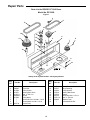
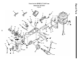
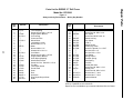
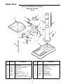
1
'3 2:1(5·60$18$/ ,1&+)/22502'(/ '5,//35(66 $VVHPEO\ 2SHUDWLRQ 5HSDLU3DUWV )RU<RXU6DIHW\ 5HDGDOOLQVWUXFWLRQVFDUHIXOO\ 48(67,21625&200(176" &$//5,'*,' Part No. SP6158 Printed in U.S.A. Table of Contents Section Page Table of Contents .......................................................... 2 Safety Instructions For Drill Press ................................. 2 Safety Signal Words ................................................... 2 Before Using The Drill Press ....................................... 2 When Installing Or Moving The Drill Press ................. 3 Before Each Use ......................................................... 3 Use Only Accessories Designed For This Drill Press To Reduce The Risk of Serious Injury From Thrown Broken Parts Or Work Pieces. ................................... 3 Plan Ahead To Protect Your Eyes, Hands, Face and Ears .................................................................... 4 Glossary of Terms ......................................................... 5 Motor Specifications and Electrical Requirements ........ 5 Power Supply and Motor Specifications ..................... 5 General Electrical Connections ................................... 5 110-120 Volt, 60 Hz. Tool Information ........................ 5 Motor Safety Protection .............................................. 6 Wire Sizes ................................................................... 6 Unpacking and Checking Contents ............................... 7 Tools Needed .............................................................. 7 Unpacking ................................................................... 7 List of Loose Parts ...................................................... 7 Loose Parts in Box and Bag ....................................... 8 Location and Function of Controls ................................. 9 Assembly ..................................................................... 10 Assembly of Base/Column ........................................ 10 Installing The Table ................................................... 11 Installing the Head .................................................... 11 Pulley Alignment and Speed Adsjustment ................ 12 Tensioning Belt ......................................................... 12 Installing Feed Handles ............................................ 13 Section Page Installing the Chuck .................................................. 13 Installing Light Bulb ................................................... 15 Adjusting the Table Square To Head ........................ 15 Bevel Scale ................................................................. 15 Getting To Know Your Drill Press ................................ 16 Drilling to a Specific Depth ........................................ 19 Another Way - Depth Scale ...................................... 19 Locking Chuck at Desired Depth .............................. 19 Removing Chuck and Arbor ...................................... 20 Re-installing the chuck and arbor ............................. 21 Safety Instructions for Basic Drill Press Operation ...... 22 Plan Ahead To Protect Your Eyes, Hands, Face and Ears ................................................................. 22 Use Only Accessories Designed For This Drill Press To Reduce the Risk of Serious Injury From Thrown Broken Parts Or Work Pieces. ................................. 22 Basic Drill Press Operation ......................................... 23 Installing Drills ........................................................... 23 Positioning Table and Workpiece ............................. 23 Tilting Table .............................................................. 24 Hole Location ............................................................ 24 Feeding ..................................................................... 24 Adjustments ................................................................. 24 Quill Return Spring ................................................... 24 Maintenance ................................................................ 25 Maintenance ............................................................. 25 Lubrication ................................................................ 25 Wiring Diagram ............................................................ 25 Troubleshooting ........................................................... 26 Repair Parts ................................................................ 27 Safety Instructions For Drill Press Safety is a combination of common sense, staying alert and knowing how your drill press works. Read this manual to understand this drill press. Safety Signal Words WARNING: means if the safety information is not followed someone could be seriously injured or killed. CAUTION: means if the safety information is not followed someone may be injured. DANGER: means if the safety information is not followed someone will be seriously injured or killed. Before Using The Drill Press WARNING: To reduce the risk of mistakes that could cause serious, permanent injury, do not plug the drill press in until the following steps have been satisfactorily completed. • Completely assemble and align drill press (See “Assembly” section). • Learn the use and function of the ON-OFF switch. (See “Getting to Know Your Drill Press” section). • Review and understand all safety instructions and operating procedures in this manual. • Review the maintenance methods for this drill press (See “Maintenance” section). • Find and read all the warning labels found on the drill press (shown at right). 2 When Installing Or Moving The Drill Press move during any use, bolt it to the floor. If the workpiece is too large to easily support with one hand, provide an auxiliary support. • To reduce the risk of injury from electrical shock, make sure your fingers do not touch the plug’s metal prongs when plugging in or unplugging the drill press. • Never Stand On Tool. Serious injury could occur if the tool tips or you accidentally hit the cutting tool. Do not store anything above or near the tool where anyone might stand on the tool to reach them. Reduce the Risk of Dangerous Environment. • Use the drill press in a dry, indoor place protected from rain. • Keep work area well lighted. • Use recommended accessories. The use of improper accessories may cause risk of injury to persons. To reduce the risk of injury from unexpected drill press movement. If there is any tendency of the drill press to tilt or Before Each Use Inspect your drill press. • To reduce the risk of injury from accidental starting, turn the switch off, unplug the drill press, and remove the switch key before raising the guard, changing the cutting tool, changing the setup, or adjusting anything. Make sure switch is in OFF position before plugging in. • Check for alignment of moving parts, binding of moving parts, breakage of parts, drill press stability, and any other conditions that may affect the way the drill press works. • If any part is missing, bent or broken in any way, or any electrical part does not work properly, turn the drill press off and unplug the drill press. • Replace damaged or missing parts before using the drill press again. • Remove adjusting keys and wrenches. Form a habit of checking for and removing keys and adjusting wrenches from table top before turning drill press on. • Make sure all clamps and locks are tight and no parts have excessive play. Use Only Accessories Designed For This Drill Press To Reduce The Risk of Serious Injury From Thrown Broken Parts Or Work Pieces • When cutting large diameter holes: - Clamp the workpiece firmly to the table. Otherwise the cutting may grab and spin it at high speed. - Use only one piece, cup-type, hole cutters. - Do not use fly cutters or multi-part hole cutters as they can come apart or become unbalanced in use. - Keep speed below 1500 R.P.M. • Drum sanders must never be operated on this drill press at a speed greater than 1800 R.P.M. • Do not install or use any drill that exceeds 7” in length or extends 6” below the chuck jaws. They can suddenly bend outward or break. • Do not use wire wheels, router bits, shaper cutters, circle (fly) cutters or rotary planers on this drill press. Kickback • Kickback is the grabbing of the workpiece by the rotating tool. The workpiece can be thrown at very high speed in the direction of rotation. This Can Cause Serious Injury. To reduce the possibility of injury from kickback: • Clamp the workpiece firmly to the table whenever possible. • Buffing or sanding wheels or drums should be contacted on the side moving away from you, not the side moving toward you. • Use only recommended accessories and follow the instructions supplied with the accessory. This drill press has 12 speeds as listed below: 250 RPM 990 RPM 340 RPM 1550 RPM 390 RPM 1620 RPM 510 RPM 1900 RPM 600 RPM 2620 RPM 650 RPM 3100 RPM See inside of guard for specific placement of belt on pulleys. Think Safety Safety is a combination of operator common sense and alertness at all times when the drill press is being used. WARNING: Do not allow familiarity (gained from frequent use of your drill press) to become commonplace. Always remember that a careless fraction of a second is sufficient to inflict severe injury. Plan Your Work • Don’t force the tool. It will do the job better and safer at the rate for which it was designed. • Use the right tool. Don’t force tool or attachment to do a job it was not designed to do. • If any part of your drill press is missing, malfunctioning, has been damaged or broken...such as the motor switch, or other operating control, a safety device or the power cord, turn the drill press off and unplug it until the particular part is properly repaired or replaced. • Never place your fingers in a position where they could contact the drill or other cutting tool if the workpiece should unexpectedly shift or your hand should slip. 3 Safety Instructions For Drill Press (continued) • To reduce the risk of injury from parts thrown by the spring, follow instructions exactly as given and shown in adjusting spring tension of quill. • To prevent the workpiece from being torn from your hands, spinning of the tool, shattering the tool or being thrown, always properly support your work so it won’t shift or bind on the tool: - Always position backup material (use beneath the workpiece) to contact the left side of the column. - Whenever possible, position the workpiece to contact the left side of the column - If it is too short or the table is tilted, clamp solidly to the table. Use table slots or clamping ledge around the outside edge of the table. - When using a drill press vise, always fasten it to a table. - Never do any work “Freehand” (hand holding workpiece rather than supporting it on the table), except when polishing. - Securely lock head to column, table support to column and table to table support before operating drill press. - Never move the head or table while the tool is running. • • • • • - Before starting the operation, jog the motor switch to make sure the drill or other cutting tool does not wobble or cause vibration. - If a workpiece overhangs the table such that it will fall or tip if not held, clamp it to the table or provide auxiliary support. - Use fixtures for unusual operations to adequately hold, guide and position workpiece. - Use the spindle speed recommended for the specific operation and workpiece material - check the inside of the belt guard for drilling information; for accessories, refer to the instructions provided with the accessories. Never climb on the drill press table, it could break or pull the entire drill press down on you. Turn the motor switch off and put away the switch key when leaving the drill press. To reduce the risk of injury from thrown work or tool contact, do not perform layout, assembly or setup work on the table while the cutting tool is rotating. Don’t overreach. Keep proper footing and balance at all times. Maintain tools with care. Keep tools sharp and clean for best and safest performance. Follow instructions for lubricating and changing accessories. Plan Ahead To Protect Your Eyes, Hands, Face and Ears Dress for safety • Do not wear loose clothing, gloves, neckties or jewelry (rings, wrist watches). They can get caught and draw you into moving parts. • Wear nonslip footwear. • Tie back long hair. • Roll long sleeves above the elbow. • Noise levels vary widely. To reduce the risk of possible hearing damage, wear ear plugs or muffs when using drill press for hours at a time. • Any power tool can throw foreign objects into the eyes. This can result in permanent eye damage. Always wear safety goggles, not glasses complying with ANSI Z87.1 (or in Canada CSA Z94-3-M88) shown on package. Everyday eyeglasses have only impact resistant lenses. They are not safety glasses. Safety goggles are available at many local retail stores. Glasses or goggles not in compliance with ANSI or CSA could seriously hurt you when they break. • For dusty operations, wear a dust mask along with safety goggles. Reduce the Risk of Accidental Starting. • Make sure switch is “OFF” before plugging drill press into a power outlet. WARNING: Don’t allow familiarity (gained from frequent use of your drill press) to cause a careless mistake. Always remember that a careless fraction of a second is enough to cause a severe injury. Keep Children Away • Keep all visitors a safe distance from the drill press. • Make sure bystanders are clear of the drill press and workpiece. Before Leaving The Drill Press • Turn the drill press off. • Wait for tool bit to stop spinning. • Unplug the drill press. • Make workshop child-proof. Lock the shop. Disconnect master switches. Remove the yellow switch key. Store it away from children and others not qualified to use the tool. 4 Glossary of Terms Workpiece The item on which the cutting operation is being performed. Drill Bit or Drill The cutting tool used in the drill press to make holes in a workpiece. Backup Material A piece of wood placed between the workpiece and table...it prevents wood in the workpiece from splintering when the drill passes through the backside of the workpice...also prevents drilling into the table top. Revolutions Per Minute (R.P.M.) The number of turns completed by a spinning object in one minute. Spindle Speed The R.P.M. of the spindle. Backlash The amount of handle movement or play between adjacent moving parts. Motor Specifications and Electrical Requirements Power Supply and Motor Specifications The A-C motor used on this tool is an induction nonreversible type, having the following specifications: WARNING: To reduce the risk of electrical hazards, fire hazards or damage to the tool, use proper circuit protection. Your tool is wired at the factory for operation using the voltage shown. Connect tool to a power line with the appropriate voltage and a 15-amp branch circuit. Use a 15-amp time delay type fuse or circuit breaker. To reduce the risk of shock or fire, if power cord is worn or cut, or damaged in any way, have it replaced immediately. Rated H.P 1/2 Voltage 110-120 Amperes 8.2 Hertz (Cycles) 60 Phase Single RPM 1725 Rotation of Shaft Clockwise General Electrical Connections DANGER: To reduce the risk of electrocution: 1. Use only identical replacement parts when servicing. Servicing should be performed by a qualified service technician. 2. Do not use in rain or where floor is wet. This tool is intended for indoor residential use only. WARNING: Do not permit fingers to touch the terminals of plug when installing or removing the plug to or from the outlet. 110-120 Volt, 60 Hz. Tool Information NOTE: The plug supplied on your tool may not fit into the outlet you are planning to use. Your local electrical code may require slightly different power cord plug connections. If these differences exist refer to and make the proper adjustments per your local code before your tool is plugged in and turned on. In the event of a malfunction or breakdown, grounding provides a path of least resistance for electric current to reduce the risk of electric shock. This tool is equipped with an electric cord having an equipment grounding conductor and a grounding plug, as shown. The plug must be plugged into a matching outlet that is properly installed and grounded in accordance with all local codes and ordinances. Do not modify the plug provided. If it will not fit the outlet, have the proper outlet installed by a qualified electrician. A temporary adapter may be used to connect this plug to a 2-prong outlet, as shown, if a properly grounded three prong outlet is not available. This temporary adapter should be used only until a properly grounded three prong outlet can be installed by a qualified electrician. The green colored rigid ear, lug and the like, extending from the adapter must be connected to a permanent ground such as a properly grounded outlet box. NOTE: In Canada the use of a temporary adapter is not permitted by the Canadian electrical code. Improper connection of the equipment grounding conductor can result in a risk of electric shock. The conductor with insulation having an outer surface that is green with or without yellow stripes is the equipment grounding conductor. If repair or replacement of the electric cord or plug is necessary, do not connect the equipment-grounding conductor to a live terminal. 5 Motor Specifications and Electrical Requirements (continued) If the grounding instructions are not completely understood, or if you are in doubt as to whether the tool is properly grounded check with a qualified electrician or service personnel. 3-Prong Plug Properly Grounded Outlet WARNING: If not properly grounded, this tool can cause an electrical shock, particularly when used in damp locations, in proximity to plumbing, or out of doors. If an electrical shock occurs there is the potential of a secondary hazard, such as your hands to hit the cutting tool. Grounding Prong NOTE: The adapter illustrated is for use only if you already have a properly grounded 2-prong outlet. NOTE: In Canada the use of a temporary adapter is not permitted by the Canadian Electrical Code. Green Grounding Lug 3-Prong Plug Adapter Make sure this Is Connected to a Known Ground 2-Prong Outlet Motor Safety Protection IMPORTANT: To avoid motor damage, this motor should be blown out or vacuumed frequently to keep sawdust from interfering with normal motor ventilation. 1. Connect this tool to a power source with the appropriate voltage for your model and a 15-amp branch circuit with a 15-amp time delay fuse or circuit breaker. Using the wrong size fuse can damage the motor. 2. If the motor won’t start, turn the switch off immediately and unplug the tool. Check the quill to make sure it turns freely. If the quill is free, try to start the motor again. If the motor still does not start, refer to the "Motor Troubleshooting Chart." 3. Fuses may "blow" or circuit breakers may trip frequently if: a. Motor Is Overloaded-Overloading can occur if you feed too rapidly or make too many start/stops in a short time. b. Line voltages should not be more than 10% above or below the nameplate voltage. For heavy loads, however, the voltage at motor terminals must equal the voltage specified for your model. c. Improper or dull drill bit is used. 4. Most motor troubles may be traced to loose or incorrect connections, overload, low voltage (such as small size wire in the supply circuit) or to overly long supply circuit wire. Always check the connections, the load and the supply circuit whenever motor doesn’t work well. Check wire sizes and length with the Wire Size Chart shown. Wire Sizes NOTE: Make sure the proper extension cord is used and is in good condition. The use of any extension cord will cause some loss of power. To keep this to a minimum and to prevent overheating and motor burnout, use the table at right to determine the minimum wire size (A.W.G.) extension cord. Use only 3-wire extension cords which have 3-prong grounding type plugs and 3-pole receptacles which accept the tools plug. 6 Extension Cord Length Gauge (A.W.G.) 0-25 25-50 16 14 Unpacking and Checking Contents Tools Needed Combination Square Must be True Draw Light Straight Edge of Line on Board Board 3/4” Thick Along this Edge This Edge Must be Perfectly Straight Medium Screwdriver Combination Square Adjustable Wrench Should be no Gap or Overlap when Square is Flipped Over in Dotted Position Unpacking WARNING: To reduce the risk of fire or toxic reaction, never use gasoline, naptha or similar highly volatile solvents to remove protective oil WARNING: To reduce the risk of injury from unexpected starting or electrical shock, do not plug the power cord into a source of power. This cord must remain unplugged whenever you are working on the drill press. 3. Apply a coat of paste wax to the table and column to prevent rust. Wipe all parts thoroughly with a clean dry cloth. NOTE: Make certain all items are accounted for, before discarding any packing material. The Drill Press is shipped complete in one box. 1. Separate all “loose parts” from packing materials and check each item with illustration and “Table of Loose Parts.” List of Loose Parts Item A B C D E F G WARNING: To reduce the risk of injury, if any parts are missing, do not attempt to assemble the drill press, plug in the power cord, or turn the switch on until the missing parts are obtained and installed correctly. 2. Remove the protective oil that is applied to the table and column. Use any ordinary household type grease and spot remover. A Description Qty. Head Asm. .........................................................1 Table...................................................................1 Column Support Assembly.................................1 Base ...................................................................1 Bag Chuck/Arbor Assembly ...............................1 Bag of Loose Parts.............................................1 Owners Manual ..................................................1 D C E F B 7 G Unpacking and Checking Contents (continued) Loose Parts in Box and Bag Key Drift (1) M10 x 1.5-40 Long Hex Head Bolt (4) Support Lock Handle (1) M10 x 1.5-12 Long Hex Socket Set Screw (2) Crank (With Set Screw) (1) M3 Hex “L” Wrench (1) Feed Handle (3) M5 Hex “L” Wrench (1) M24 Hex Box Wrench (1) Chuck Key (1) Key-Switch (1) Chuck/Arbor (1) Assembly 8 Location and Function of Controls 11 10 1 2 9 3 8 7 4 1 5 12 6 16 15 14 13 Table Removed for Clarity 1. Belt Tension Lock Handles...Tightening handles locks motor bracket support to maintain correct belt distance and tension. 2. Belt Tension Handle...Turn handle counterclockwise to apply tension to belt, turn handle clockwise to release belt tension. 3. Head Lock Set Screws...Locks the head to the column. Always have them locked in place while operating the drill press. 4. Feed Handle...For moving the chuck up or down. One or two of the handles may be removed if necessary whenever the workpiece is of such unusual shape that it interferes with the handles. 5. Table Crank...Turn clockwise to elevate table. Support lock must be released before operating crank. 6. Chuck Key...Used to tighten drill in the chuck and also to loosen the chuck for drill removal. 7. Chuck...Holds drill bit or other recommended accessory to perform desired operations. 8. Depth Scale...Allows operator to adjust drill press to drill to a desired depth. 9. Drill “On-Off” Switch...Has locking feature to prevent unauthorized and possible hazardous use by children and others. 10. Light “On-Off” Switch...Turns the light on and off. 11. Depth Scale Lock...Locks the depth scale at selected depth. 12. Spring Cap...Provides means to adjust quill spring tension. 13. Table Lock...Allows table to be rotated in various positions and locked. 14. Table Bevel Lock...Locks the table in any position from 0°- 45°. 15. Bevel Scale...Shows degree table is tilted for bevel operations. Scale is mounted on side of arm. 16. Support Lock Handle...Tightening locks table support to column. Always have it locked in place while operating the drill press. Note and follow the safety warnings and instructions that appear on the panel on the right side of the head. 9 Assembly WARNING: To reduce the risk of injury from unexpected starting or electrical shock, never connect plug to outlet until all assembly steps are completed and you read and understand all instructions. 10mm Dia. x 40mm Hex Head Bolt (4) Assembly of Base/Column 1. Locate four (4) 10mm dia. x 40mm long bolts among loose parts bag. 2. Position base on floor. Remove protective covering and discard. 3. Remove protective sleeve from column tube and discard. Place column assembly on base, and align holes in column support with holes in base. 4. Install a bolt in each hole through column support and base and tighten with adjustable wrench. Column Support Base Column 5. Locate table crank and support lock in loose parts box. 6. Install support lock from left side into table support and tighten by hand. 7. Install table crank assembly and tighten set screw with a 3mm hex “L” wrench. Do not overtighten. Set screw should be tightened against the flat section of the shaft. NOTE: To minimize crank backlash, tighten support lock, rotate elevation worm shaft clockwise, then assemble crank tight against table support and tighten set screw. Support Lock Table Support Elevation Worm Shaft Handle Table Support Table Crank 8. Check column collar for proper adjustment. Collar should not be angled on the column and it should be positioned so rack will slide freely in collar when table is rotated 360° around column tube. If readjusted, only tighten set screw enough to keep collar in place. NOTE: To reduce the risk of column or collar damage, do not overtighten set screw. Column Collar Rack Column 10 Do Not Overtighten Set Screw Installing The Table Table Crank Support Lock 1. Loosen support lock and raise table support by turning table crank clockwise until support is at a working height level. Tighten support lock. Table Support Column Rack Table Support 2. Remove protective covering from table and discard. Loosen table lock, place table in table support and tighten table lock (located under table) by hand. NOTE: If table won’t fit into table support easily, pry open table support with a flat blade screwdriver. Table Table Lock Installing the Head CAUTION: The head assembly weights about 61 pounds. To reduce the risk of back injury get help to lift the head. 10mm Dia. x 12mm Set Screw 1. Locate (2) two 10mm dia. x 12mm long set screws in loose parts bag. 2. Remove protective bag from head assembly and discard. Carefully lift head above column tube and slide it onto column making sure head slides down over column as far as possible. Align head with table and base. Head Column 3. Install a set screw in each hole (as indicated) on the right side of the head, and using a 5mm hex “L” wrench, tighten the two head lock set screws. Head Lock Set Screws Head 11 Assembly (continued) Pulley Alignment and Speed Adjustment Checking Pulley(s) Alignment Straightedge WARNING: To reduce the risk of injury due to accidental starting always turn drill press off and remove switch key before making belt adjustments. The pulleys and motor are assembled at the factory and should not require further adjustment. If the pulleys or motor are removed for service, follow the pulley alignment instructions below. 1. Place a straightedge such as a piece of wood, metal, or framing square across the top of pulleys. 2. The top of all three pulleys should touch the straightedge 3. If not: • Loosen the motor mount nuts. • Move the motor until the pulleys are in line. • Retighten the motor mount nuts. NOTE: To avoid rattles or other noise, motor frame must not touch lower belt guard. Lower Belt Guard Belt Tension Lock Handle Motor Mount Nuts Speed Adjustment 1. Release belt tension lock handles located on each side of drill press head by turning them counterclockwise. 2. Loosen belt tension by turning belt tension handle clockwise. Motor Belt Tension Handle Spindle Pulley 3. Use speed chart inside belt guard to choose speed for drilling operation. Install belts in correct position for desired speed. The longer of the two belts is always positioned between the spindle pulley and idler pulley. NOTE: Refer to inside belt guard for Recommended Drilling Speeds. Idler Pulley Tensioning Belt Belt Tension Lock Handle 1. Apply tension to belt by turning belt tension handle counterclockwise until belt deflects approximately 1/2 inch by thumb pressure at its center. 2. Tighten belt tension lock handles. NOTE: Over tensioning belt may cause motor not to start or damage bearings. 3. If belt slips while drilling, readjust belt tension. Belt Tension Handle 12 Installing Feed Handles Hub 1. Locate three (3) feed handles among loose parts. 2. Screw the feed handles into the threaded holes in the hub and tighten. 3. Tighten feed handles using M24 wrench. Tighten Using M24 Wrench Feed Handle Installing the Chuck/Arbor Assembly Quill 1. Clean the tapered surfaces on the arbor and spindle with a clean cloth. Make sure there are no foreign particles sticking to these surfaces. The slightest piece of dirt on these surfaces will prevent the arbor from seating properly. This will cause the drill to “wobble”. 2. Slide arbor into spindle on drill press. 3. Push up on chuck/arbor assembly as you rotate them. You will feel rectangular end of arbor slip into a notch in the spindle. Spindle Tapered Surface Arbor Tapered Surface Chuck Sleeve WARNING: Make sure the rectangular end of the arbor has slipped into the notch in the spindle before going on the step 4. Failure to follow this direction may allow the chuck to come loose during operation, fly out and hit the operator. Chuck Body 13 Assembly (continued) 4. Unlock support lock and raise table so its about two (2) inches below tip of chuck. Support Lock Chuck Sleeve 5. Turn chuck sleeve clockwise and open jaws in chuck completely. Chuck 6. Place a piece of wood on table. Turn feed handles counterclockwise and force chuck against table until chuck is secure. Feed Handle Wood 14 Installing Light Bulb 1. Install a light bulb (not larger than 60 watt) into the socket inside the head. Adjusting the Table Square To Head NOTE: The combination square must be “true”. See “Unpacking and Checking Contents” section for method. 1. Insert precision round steel rod or straight drill bit approximately 3” long into chuck and tighten. 2. With table raised to working height and locked on column, place combination square flat on table beside rod or bit. 3. If an adjustment is necessary, loosen the set screw under bevel lock with 3mm “L” wrench, then loosen the table bevel lock bolt with the 24mm flat wrench (included). (This adjustment is located under the table). 4. Align the table square to the rotor bit by rotating table until the square and rod or bit are in line. 5. Retighten table bevel lock. 6. Retighten set screw. Table Set Screw Table Bevel Lock Bevel Scale Table NOTE: The bevel scale has been included to provide a quick method for beveling the table to approximate angles. If precise accuracy is necessary, a square, or other precision measuring tool should be used to position the table. 1. To use the bevel scale do the following. a. Loosen set screw and table bevel lock (see step 3 above). b. Move table so desired angle on bevel scale is straight across from zero line on table. c. Retighten table bevel lock and set screw. Pointer Scale 15 Getting To Know Your Drill Press Feed Spring Adjustment Feed Spring 17 Spring Cap 1 Belt Guard Light “On-Off” Switch 25 Drill Speed Table (Inside Belt Guard) 26 Drill “On-Off” 2 Belt Tension Lock Handle Switch 18 Chuck 24 Chuck 19 Arm Key 21 Table Lock 23 Support Lock 2 Belt Tension Lock Handle 16 Depth 22 Bevel Scale 20 Table Bevel Lock Scale Lock 3 Belt Tension (Under Table) Handle 4 Head Lock 15 Depth Scale 5 Feed Handle Indicator Quill and Spindle Assembly Inside of Drill Press Splines (Grooves) 6 Column Collar 14 Depth Scale 7 Table Support Spindle 13 Table Rack (Teeth) 8 Table Crank Key Drift 12 Column 9 Rack 11 Column Support Arbor 18 Chuck 10 Base 16 Spindle Speed in R.P.M. 1. Belt Guard...Covers pulleys and belt during operation of drill press. 2. Belt Tension Lock Handle...Tightening handle locks motor bracket support to maintain correct belt distance and tension. 3. Belt Tension Handle...Turn handle counterclockwise to apply tension to belt, turn handle clockwise to release belt tension. Refer to section “AssemblyInstalling and Tensioning Belt”. 4. Head Lock Set Screws...Lock the head to the column. Always have them locked in place while operating the drill press. 5. Feed Handle...For moving the chuck up or down. One or two of the handles may be removed if necessary whenever the workpiece is of such unusual shape that it interferes with the handles. 6. Column Collar... Holds the rack to the column. Rack remains movable in collar to permit table support movements. 7. Table Support...Rides on column to support arm and crank. 8. Table Crank...Turn clockwise to elevate table. Support lock must be released before operating crank. 9. Rack...Combines with gear mechanism to provide easy elevation of table by hand operated table crank. 10. Base...Supports drill press. For additional stability, holes are provided in base to bolt drill press to floor. (See “Additional Safety Instructions for Drill Presses”. 11. Column Support...Supports column, guides rack, and provides mounting holes for column to base. 12. Column...Connects head, table and base on a onepiece tube for easy alignment and movement. 13. Table...Provides working surface to support workpiece. 14. Depth Scale...Shows depth of hole being drilled in inches and millimeters. 15. Depth Scale Indicator...Indicates drilling depth selected on depth scale. 16. Depth Scale Lock...Locks the depth scale to selected depth. 17. Spring Cap...Provides means to adjust quill spring tension. 18. Chuck...Holds drill bit or other recommended accessory to perform desired operations. 19. Arm...Extends beyond table support for mounting aligning the table. 20. Table Bevel Lock...Locks the table in any position from 0°- 45°. 21. Table Lock...Table can be rotated in various positions and locked. 22. Bevel Scale...Shows degree table is tilted for bevel operations. Scale is mounted on table support, if it is to be used for quick reference where accuracy is not critical. 23. Support Lock...Tightening locks table support to column. Always have it locked in place while operating the drill press. 24. Chuck Key...It is a self ejecting chuck key which will “pop” out of the chuck when you let go of it. This action is designed to help prevent throwing of the chuck key from the chuck when power is turned “ON”. Do not use any other key as a substitute, order a new one if damaged or lost. 25. Drill Speed...Table...Drill Speed can be changed by placing the belt in any of the steps (grooves) in the pulleys. The spindle speed chart, as shown above, lists belt positions for the various spindle speeds. 17 Getting To Know Your Drill Press (continued) 26. On-Off Switch...Has locking feature. This feature is intended to prevent unauthorized and possible hazardous use by children and others. Insert key into switch. NOTE: Key is made of yellow plastic. Key To turn drill ON, insert finger under switch lever and pull. To turn drill OFF, push lever in. NOTE: In an emergency: If the drill bit binds, stalls, stops or tends to tear the workpiece loose, you can quickly turn the drill off by hitting the switch with the palm of your hand. To lock switch in OFF position, hold switch IN with one hand and remove key with other hand. WARNING: For your own safety, always push the switch “OFF” when drill press is not in use, remove key and keep it in a safe place, also, in the event of a power failure (all of your lights go out) or blown fuse or tripped circuit breaker, turn switch off, lock it and remove the key. This will prevent the drill press from starting up again when the power comes back on. 18 Drilling to a Specific Depth Depth Scale Lock To drill a blind hole (not all the way through) to a given depth, proceed as follows. 1. Mark the depth of the hole on the workpiece. 2. Loosen the depth scale lock. 3. With the switch OFF, bring the drill bit down until the tip of lips of the bit are even with the mark. 4. Turn the depth scale counterclockwise until it stops moving. 5. Tighten the depth scale lock. 6. The drill bit will stop at this depth until the depth scale is readjusted. Depth Scale Indicator Another Way - Depth Scale Depth Scale 1. With the power off, loosen the depth scale lock. 2. Place workpiece on table. Adjust table until the tip of the drill bit is just a little above the top of the workpiece, turn the depth scale counterclockwise to zero. 3. Turn the depth scale clockwise until the depth scale indicator points to the desired drilling depth on the depth scale. 4. Tighten the depth scale lock. 5. The chuck or drill will now be stopped after traveling downward the distance selected on the depth scale. Mark Locking Chuck at Desired Depth Depth Scale Lock 1. With the switch off, loosen the depth scale lock. 2. Turn the feed handles until the chuck is at the desired depth. Hold feed handles at this position. 3. Turn the depth scale clockwise until it stops. 4. Tighten the depth scale lock. 5. The chuck will now be held at this depth when the feed handles are released. Depth Scale Adjust to Desired Depth 19 Getting To Know Your Drill Press (continued) Removing Chuck and Arbor Arbor 1. With the switch OFF, adjust depth scale to hold drill at a depth of (3) three inches. (See instructions for “Locking chuck at desired depth”). 2. Align key holes in spindle and quill by rotating the chuck by hand. (See illustration) 3. Insert key drift into key holes. 4. Tap key drift lightly until the chuck and arbor fall out of spindle. NOTE: Place one hand below chuck to catch it when it falls out. Spindle Key Hole Quill Quill Key Hole Chuck Sleeve Key Drift Chuck Sleeve Chuck Body 20 Re-installing the chuck and arbor 1. Clean the tapered surfaces on the arbor and spindle with a clean cloth. Make sure there are no foreign particles sticking to these surfaces. The slightest piece of dirt on these surfaces will prevent the arbor from seating properly. This will cause the drill to “wobble”. 2. Slide arbor into spindle on drill press. 3. Push up on chuck/arbor assembly as you rotate them. You will feel rectangular end of arbor slip into a notch in the spindle. Quill Spindle Tapered Surface Arbor Tapered Surface Chuck Sleeve WARNING: Make sure the rectangular end of the arbor has slipped into the notch in the spindle before going on the step 4. Failure to follow this direction may allow the chuck to come loose during operation, fly out and hit the operator. Chuck Body 4. Unlock support lock and raise table so its about two (2) inches below tip of chuck. 5. Turn chuck sleeve clockwise and open jaws in chuck completely. 6. Place a piece of wood on table.Turn feed handles counterclockwise and force chuck against table until arbor is secure. Support Lock Tip of Chuck Chuck Sleeve Feed Handle Chuck Wood 21 Safety Instructions for Basic Drill Press Operation Read the following instructions for operating your drill press to get the best results and to minimize the likelihood of personal injury. WARNING For your own safety, always observe the safety precautions here and on pages 2, 3 and 4. Plan Ahead To Protect Your Eyes, Hands, Face and Ears Dress for safety • Do not wear loose clothing, gloves, neckties or jewelry (rings, wrist watches). They can get caught and draw you into moving parts. • Wear nonslip footwear. • Tie back long hair. • Roll long sleeves above the elbow. • Noise levels vary widely. To reduce the risk of possible hearing damage, wear ear plugs or muffs when using drill press for hours at a time. Plan Your Work • Don’t force the tool. It will do the job better and safer at the rate for which it was designed. • Use the right tool. Don’t force tool or attachment to do a job it was not designed to do. • If any part of your drill press is missing, malfunctioning, has been damaged or broken...such as the motor switch, or other operating control, a safety device or the power cord, turn the drill press off and unplug it until the particular part is properly repaired or replaced. • Never place your fingers in a position where they could contact the drill or other cutting tool if the workpiece should unexpectedly shift or your hand should slip. • To reduce the risk of injury from parts thrown by the spring, follow instructions exactly as given and shown in adjusting spring tension of quill. • To prevent the workpiece from being torn from your hands, spinning of the tool, shattering the tool or being thrown, always properly support your work so it won’t shift or bind on the tool: - Always position backup material (use beneath the workpiece) to contact the left side of the column. - Whenever possible, position the workpiece to contact the left side of the column - If it is too short or the table is tilted, clamp solidly to the table. Use table slots or clamping ledge around the outside edge of • • • • • the table. - When using a drill press vise, always fasten it to a table. - Never do any work “Freehand” (hand holding workpiece rather than supporting it on the table), except when polishing. - Securely lock head to column, table support to column and table to table support before operating drill press. - Never move the head or table while the tool is running. - Before starting the operation, jog the motor switch to make sure the drill or other cutting tool does not wobble or cause vibration. - If a workpiece overhangs the table such that it will fall or tip if not held, clamp it to the table or provide auxiliary support. - Use fixtures for unusual operations to adequately hold, guide and position workpiece. - Use the spindle speed recommended for the specific operation and workpiece material - check the inside of the belt guard for drilling information; for accessories, refer to the instructions provided with the accessories. Never climb on the drill press table, it could break or pull the entire drill press down on you. Turn the motor switch off and put away the switch key when leaving the drill press. To reduce the risk of injury from thrown work or tool contact, do not perform layout, assembly or setup work on the table while the cutting tool is rotating. Don’t overreach. Keep proper footing and balance at all times. Maintain tools with care. Keep tools sharp and clean for best and safest performance. Follow instructions for lubricating and changing accessories. Use Only Accessories Designed For This Drill Press To Reduce the Risk of Serious Injury From Thrown Broken Parts Or Work Pieces • When cutting large diameter holes: - Clamp the workpiece firmly to the table. Otherwise the cutting may grab and spin it at high speed. - Use only one piece, cup-type, hole cutters. - Do not use fly cutters or multi-part hole cutters as they can come apart or become unbalanced in use. - Keep speed below 1500 R.P.M. • Drum sanders must never be operated on this drill press at a speed greater than 1800 R.P.M. • Do not install or use any drill that exceeds 7” in length or extends 6” below the chuck jaws. They can suddenly bend outward or break. • Do not use wire wheels, router bits, shaper cutters, circle (fly) cutters or rotary planers on this drill press. 22 Basic Drill Press Operation Installing Drills Chuck Key Insert drill into chuck far enough to obtain maximum gripping of the chuck jaws. The jaws are approximately 1" long. When using a small drill do not insert it so far that the jaws touch the flutes (spiral grooves) of the drill. Make sure that the drill is centered in the chuck before tightening the chuck with the key. Tighten the drill sufficiently, so that is does not slip while drilling. Turn the chuck key clockwise to tighten, counterclockwise to loosen. Chuck Jaws Positioning Table and Workpiece Lock the table to the column in a position so that the tip of the drill is just a little above the top of the workpiece. Always place a piece of backup material (wood, plywood, etc.) on the table underneath the workpiece. This will prevent “splintering” or making a heavy burr on the underside on the workpiece as the drill breaks through. To keep the backup material from spinning out of control, it must contact the left side of the column, as illustrated. Workpiece WARNING: To prevent the workpiece or the backup material from being torn from your hand while drilling, position them against the left side of the column. If the workpiece or the backup material are not long enough to reach the column, clamp them to the table. Failure to do this could result in personal injury. Backup Material For small pieces that cannot be clamped to the table, use a drill press vise (optional accessory). WARNING: The vise must be clamped or bolted to the table to reduce the risk of injury from spinning work and vise or tool breakage. Workpiece Drill Press Vise Bolt or Clamp Vise Securely 23 Basic Drill Press Operation (continued) Tilting Table To use the table in a bevel (tilted) position, loosen the set screw under table bevel lock with hex “L” wrench. Loosen bevel lock bolt with the 24mm flat wrench (included). Tilt table to desired angle by reading bevel scale. Retighten bevel lock and set screw. Bevel Lock WARNING: To reduce the risk of injury from spinning work or tool breakage, always clamp workpiece and backup material securely to table before operating drill press with the table tilted. Bevel Scale To return table to original position: Loosen set screw and bevel lock, tilt table back to 0° on bevel scale and retighten set screw, then tighten bevel lock. Set Screw Feeding Pull down on the feed handles with only enough effort to allow the drill to cut. Feeding too slowly might cause the drill to burn. Feeding too rapidly might stop the motor, cause the belt or drill to slip, tear the workpiece loose or break the drill bit. When drilling metal, it may be necessary to lubricate the tip of the drill with cutting oil or motor oil to prevent burning of the drill tip. Hole Location Make a dent in the workpiece where your want the hole, using a center punch or a sharp nail. Before turning the switch on, bring the drill down to the workpiece lining it up with the hole location. Adjustments WARNING: For your own safety turn switch “OFF” and remove plug from power source outlet before making any adjustments. To reduce the risk of injury from thrown parts due to spring release, follow instructions carefully and wear eye goggles. Notch Boss Quill Return Spring NOTE: The return spring tension is set at the factory and should not require further adjustment. 1. With the chuck at its highest possible position, turn the depth scale clockwise until it stops and tighten the depth scale lock. This will prevent the quill dropping while tensioning the spring. 2. Lower table for additional clearance. 3. Work from left side of drill press. 4. Place screwdriver in lower front notch of spring cap, and hold it in place while loosening and removing (outer) nut only. 5. With screwdriver remaining in notch, loosen (inner) nut (approximately 1/8") until notch disengages from boss on head. Do not remove this nut. 6. Carefully turn screwdriver counterclockwise and engage next notch in boss. Do not remove screwdriver. 7. Tighten standard nut with wrench only enough to engage boss. Do not overtighten as this will restrict quill movement. 8. Move stop nuts and depth pointer to upper most position and check tension while turning feed handles. Nut (Outer) Spring Cap Notch Nut (Inner) 9. If there is not enough tension on spring, repeat steps 4-8 moving only one notch each time and checking tension after each repetition. 10. Proper tension is achieved when quill returns gently to full up position when released from 3/4” depth. 11. When there is enough tension after checking, replace outer nut and tighten to inner nut. But do not overtighten against inner nut. 12. Check quill while feeding to have smooth and unrestricted movement. If movement is too tight, loosen outer nut and slightly loosen inner nut until unrestricted. Retighten outer nut. 24 Maintenance Maintenance Lubrication All of the ball bearings are packed with grease at the factory. They require no further lubrication. Periodically lubricate the table elevation mechanism, the splines (grooves) in the spindle, and the rack (teeth of the quill). See “Getting to Know Your Drill Press”. WARNING: For your own safety, turn switch “OFF” and remove plug from power source outlet before maintaining or lubricating your drill press. Frequently blow out any dust that may accumulate inside the motor. A coat of automotive type paste wax applied to the table and column will help to keep the surfaces clean. WARNING: To reduce the risk of shock or fire hazard, if the power cord is worn or cut, or damaged in any way, have it replaced immediately. Wiring Diagram Motor 1 Black Motor Cord 4 Green Black White Green Wire Connector White Power Switch White Black Jumper Light Black Power Cord White Green 25 Black Light Switch Troubleshooting WARNING: For your own safety, turn switch “OFF” and always remove plug from power source outlet before troubleshooting. Consult your Authorized Service Center if for any reason motor will not run. Trouble Noisy Operation Probable Cause Remedy 1. Incorrect belt tension. 1. Adjust tension. See “Installing and Tensioning Belt” section. 2. Lubricate spindle. See “Lubrication” section. 3. Checking tightness of retaining nut on pulley, and tighten if necessary. 4. Tighten set screws in pulleys. 2. Dry spindle. 3. Loose spindle pulley 4. Loose motor pulley Drill bit burns 1. Incorrect speed 2. Chips not coming out of hole 3. Dull drill bit 4. Feeding too slow 5. Not lubricated Drill bit leads off, hole not round 1. Change speed. See “Getting to Know Your Drill Press” section. 2. Retract drill bit frequency to clear chips 3. Resharpen drill bit 4. Feed fast enough, allow drill bit to cut 5. Lubricate drill bit. See “Basic Drill Press Operation” section. 1. Hard grain in wood or lengths of cutting lips and/ or angles not equal. 2. Bent drill bit 1. Resharpen drill bit correctly Wood splinters on underside 1. No “backup material” under workpiece 1. Use “backup material”. See “Basic Drill Press Operation” section. Workpiece torn loose from hand 1. Not supported or clamped properly 1. Support or clamp workpiece. See “Basic Drill Press Operation” section. Drill bit binds in workpiece 1. ‘Workpiece pinching drill bit or excessive feed pressure. 2. Improper belt tension 1. Support or clamp workpiece. See “Basic Drill Press Operation” section. 2. Adjust tension. See “Installing and Tensioning Belt” section. Excessive drill bit runout or wobble. 1. Bend drill bit 2. ‘Worn spindle bearings 3. Drill bit not properly installed in chuck 4. Chuck not properly installed 1. Use a straight drill bit. 2. Replace bearings 3. Install drill bit properly. See “Basic Drill Press Operation” section. 4. Install chuck properly, refer to “Assembly- Installing the Chuck”. Quill returns too slow or too fast 1. Spring has improper tension 1. Adjust spring tension. See “Adjustments - Quill Return Spring” section. Chuck will not stay attached to spindle, it falls off when trying to install. 1. Dirt, grease or oil on the tapered inside surface of chuck or on the spindles tapered surface. 1. Using a household detergent, clean the tapered surface of the chuck and spindle to remove all dirt, grease and oil. 26 2. Replace drill bit Repair Parts Parts List for RIDGID 15" Drill Press Model No. DP15000 Figure 1 4 5 17 12 3 16 14 6 15 13 2 1 14 8 7 12 10 11 9 19 18 Always order by Part Number - Not by Key Number Key No. 1 2 3 4 5 6 7 8 9 10 Part No. Description 817325 508047 817544 813271 817511-1 822039-1 817543 Knob Pivot Idler Pulley Center Bearing Ball 15mm Belt “V” 3/8 x 24 Guard Pulley Motor Screw Hex Soc. Set M6 x 1.0-10 Screw Wash. Hd. M6 x 1.0-16 Insert Pulley * * 821734 * Standard hardware item - may be purchased locally. 27 Key No. Part No. 11 12 13 14 15 16 17 18 19 817537 817545 817530 817536 821742 817511-2 820294 * * Description Screw Pan. Hd. M5 x 0.8-12 Ring Retaining Pulley Spindle Bearing Ball 20mm Spacer Nut Pulley M24 x 1.5 L.H. Belt “V” 3/8 x 26 Washer Foam Lockwasher M6 Ext. Figure 2 49 48 47 5 4 9 6 7 8 46 45 1 2 44 3 43 42 11 37 38 39 28 40 14 13 41 11 12 15 36 34 16 35 17 33 18 19 26 32 21 27 20 25 22 28 29 31 24 30 23 10 Repair Parts Parts List for RIDGID 15" Drill Press Model No. DP15000 Figure 2 Always order by Part Number -- Not by Key Number Key No. 29 1 2 3 4 5 6 7 8 9 10 11 12 13 14 15 16 17 18 19 20 21 22 23 24 25 Part No. 817317 * 817495 821739-1 * 817336-1 * * 826672 * * 821740-1 * 817516 817320 817494 * 817303 817343 817300 826441 826445 826447-1 817774 822216-6 Description Lever Adjusting Screw Hex Hd. M8 x 1.25-16 Support Motor Bracket Cord w/Plug Connector Wire Mount Motor Lockwasher 12mm Nut Hex M12 x 1.75 • Motor Nut Hex M8 x 1.25 Washer M8 x 16 x 1.6 Cord Motor Screw Hex Hd. M8 x 1.25-20 Support Motor Bracket Knob Motor Adjusting Handle Belt Tension Screw Hex Soc. Set M10 x 1.5-12 Pin Stop Lock Depth Screw Guide Scale Knob Rod Hub Asm. Ring Depth Stop w/Scale Head * Standard hardware item - may be purchased locally. Key No. 26 27 28 29 30 31 32 33 34 35 36 37 38 39 40 41 42 43 44 45 46 47 48 49 Description * * 826405 * 826347 826122 821741 817354 826435 817308 * * 817307 817306 817305 817304 60475 817321 * 63418 * 813317-6 813317-8 SP6158 Lockwasher Ext. M5 Screw Pan Hd. M5 x 0.8-8 Box Switch Screw Pan Hd M5 x 0.8-16 Switch Locking Key Switch Lead 3" Switch Rocker Holder Key Chuck Screw Sl. Special 10 x 1.5-27 Nut Hex M10 x 1.5 Nut Hex M12 x 1.5-8 Cap Spring Spring Torsion Retainer Spring Seat Spring Tie Wire Socket Bulb Asm. Screw Pan Hd. M6 x 1.0-12 Clamp Cord Screw Pan Hd. M5 x 0.8-12 Wrench Hex “L” 3mm Wrench Hex “L” 5mm Owners Manual • Any attempt to repair this motor may create a hazard unless repair is done by a qualified service technician. Repair service is available at your nearest Authorized Service Center. Repair Parts Parts List for RIDGID 15" Drill Press Model No. DP15000 Repair Parts Parts List for RIDGID 15" Drill Press Model No. DP15000 Figure 3 12 1 2 3 4 11 5 6 7 10 9 8 Always order by Part Number - Not by Key Number Key No. 1 2 3 4 5 6 Part No. 817309 817310 817311 813480 817535 817532 Description Lock Nut M17 x 1.0 Ring Locking Washer Bearing Ball 17mm Gasket Quill Tube Quill 30 Key No. Part No. 7 8 9 10 11 12 817326 817339 817340 817341 817531 817529 Description Key Drift Key Chuck Chuck Arbor Spindle Bearing Ball Repair Parts Parts List for RDIGID 15" Drill Press Model No. DP15000 Figure 4 1 18 15 2 4 17 5 3 16 10 6 11 14 7 2 9 2 12 13 8 19 Key No. 1 2 3 4 5 6 7 8 9 10 Part No. 821883 * 821861-2 821880 821882 821881-1 * 817577-1 826439 * Key No. Description Collar Rack Screw Hex Soc. Set M6 x 1.0-10 Support Table w/Indicator Tube Column Rack Support Column Screw Hex Hd. M10 x 1.5-40 Base Crank (Includes Set Screw) Screw Hex Soc. Set M10 x 1.5-12 11 12 13 14 15 16 17 18 19 * Standard hardware item - may be purchased locally. 31 Part No. 817288 * 817290-3 817777-3 817575-1 817294-2 817350 817349 826438 Description Pin Gear Screw hex Hd. M16 x 2.0-35 Clamp Table Arm Table w/Scale Table Clamp Column Gear Helical Worm Elevation Wrench Hex 24mm Lifetime Warranty On RIDGID Tools The RIDGID REPUTATION is the result of the consistent product quality and years of pride in workmanship. Rigorous checks and controls from raw materials to packaged products insure product confidence widely accepted as the mark of the professional trades. Therefore, RIDGID covers its products with a LIFETIME WARRANTY against defects in material or workmanship. To take advantage of this warranty, the complete product must be delivered prepaid to any RIDGID AUTHORIZED SERVICE CENTER. Obviously, failures due to misuse, abuse or normal wear and tear are not covered by this warranty. NO OTHER WARRANTY, WRITTEN OR ORAL, APPLIES. No employee, agent, dealer or other person is authorized to give any warranty on behalf of RIDGID Power Tools, Emerson Electric Co. Warranted products will be repaired or replaced, at our option, at no charge to you and returned to you via prepaid transportation. Such replacement or repair is the exclusive remedy available from RIDGID Power Tools, Emerson Electric Co. Emerson Electric Co. is not liable for damage of any sort, including incidental and consequential damages. Some U.S.A. states do not allow the exclusion or limitation of incidental or consequential damages, so the above limitation or exclusion may not apply. This warranty gives you specific legal rights, and you may have other rights which vary from state to state. Stock No. DP1500 Model No. DP15000 Model and serial numbers may be found at the left side of the head. You should record both model and serial number in a safe place for future use. QUESTIONS OR COMMENTS? CALL 1-800-4-RIDGID RIDGID Power Tools Emerson Electric Co. © 1998 Emerson Electric Co. Part No. SP6158 Form No. SP6158-2 Printed in U.S.A. 6/99