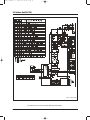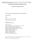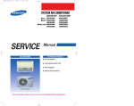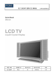
1
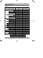
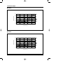
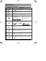
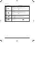
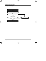
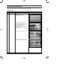
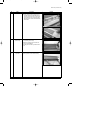
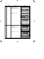
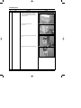
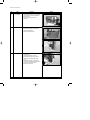
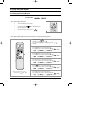
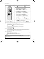
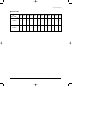
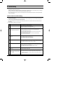
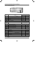
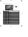
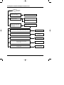
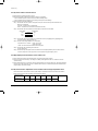
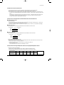
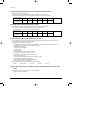
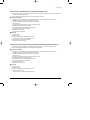
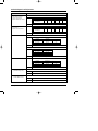
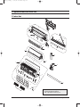
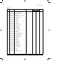
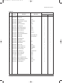
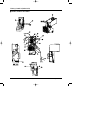
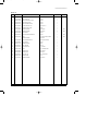
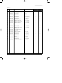
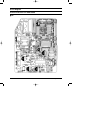
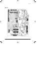
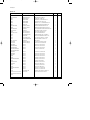
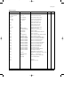
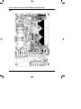
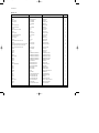
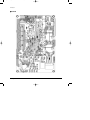
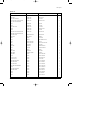
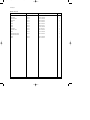
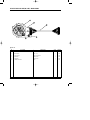
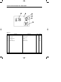
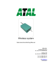
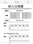
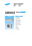
DB98_17175A_co 2/6/04 4:12 PM Page 3 ROOM AIR CONDITIONER INDOOR UNIT OUTDOOR UNIT SH09BPH SH12BPH SH09BPHX SH12BPHX SERVICE AIR CONDITIONER Manual CONTENTS 1. Product Specifications 2. Operating Instructions 3. Disassembly and Reassembly 4. Refrigerating Cycle Diagram 5. Set Up the Model Option 6. Troubleshooting 7. Exploded Views and Parts List 8. PCB Diagram 9. Wiring Diagram DB98_17175A_1 2/6/04 4:13 PM Page 1 1. Product Specifications 1-1 Table Model Power Source ø-V-Hz 1-220/240-50 1-220/240-50 W 2,800(1,500~3,400) 3,500(1,500~4,000) BTU/h 9,500(5,100~11,600) 11,900(5,100~13,600) Energy Efficiency Ratio BTU/wh 11.8(10.0~13.8) 10.9(10.2~13.8) Air Flow m3/min 5.5 6.5 \/h 1.5 1.6 34 39 53 53 Capacity Cooling Moisture Removal Noise Level Indoor Noise Level Outdoor Performance 3,200(1,500~4,500) 4,000(1,500~5,000) BTU/h 10,900(5,100~15,300) 13,600(5,100~17,000) Energy Efficiency Ratio BTU/wh 13.6(10.2~14.6) 11.6(10.0~14.6) Air Flow m /min 7.5 8.3 39 42 53 53 3 Noise Level Indoor Noise Level Outdoor Available Voltage Range V 187~264 187~264 A 3.6(2.0~4.9) 4.8(2.0~5.9) Power Input W 800(370~1,150) 1,090(370~1,330) Power Factor % 96.6(84.5~97.6) 98.0(82.3~98.7) Running Amperes A 4.0(1.8~6.5) 5.5(1.8~7.2) Power Input W 880(350~1,500) 1,170(350~1,700) Power Factor % 95.6(81.8~98.6) 97.8(81.8~98.4) A 10↓ 10↓ Fuse Capacity AxV 3.15 x 250 / 20 x 250 3.15 x 250 / 20 x 250 Power Cord AxV 15 x 250 15 x 250 mm3 x G 1.5 x 4 1.5 x 4 Heating Starting Current Cable-Connector Compressor Type - Single Rotary Single Rotary Model Name - G4C090LU1ER G4C090LU1ER Safety Devices - 204CT 204CT - YDK-204F8C-1 YDK-204F8C-1 µF x VAC 1.2µF / 450V 1.2µF / 450V - AMASS-020WTVB SIC-52FV-D828-1 µF x VAC 1.7µF / 450V - UKV-18D11 UKV-18D11 Indoor Fan Motor Outdoor Model Name Running Capacitor Model Name Running Capacitor Refrigerant Tube EEV Refrigerant to Charge (R410A) Dimension Weigth dBA Running Amperes Cooling Electrical Rating dBA W Capacity Heating SH12BPH SH12BPHX SH09BPH SH09BPHX Item g 1000 1000 Indoor unit : W x H x D mm 890 x 285 x 180 890 x 285 x 180 Outdoor unit : W x H x D mm 720 x 548 x 265 720 x 548 x 265 Indoor unit kg 9 9 Outdoor unit kg 33.8 33.8 Remark : Text condition Samsung Electronics Indoor room Outdoor room Cooling test DB27˚C / WB19˚C DB35˚C / WB24˚C Heating test DB20˚C / WB15˚C DB 7˚C / WB 6˚C 1 DB98_17175A_1 2/6/04 4:13 PM Page 2 1-2 Pressure Graph ■ SH09BPH 10.5 Pressure (kgf/cm2g) 10.0 9.5 9.0 8.5 8.0 7.5 7.0 6.5 20 25 30 35 40 45 40 45 Outdoor Temp. (ßC) ■ SH12BPH 10.5 Pressure (kgf/cm2g) 10.0 9.5 9.0 8.5 8.0 7.5 7.0 6.5 20 25 30 35 Outdoor Temp. (ßC) 2 Samsung Electronics DB98_17175A_1 2/6/04 4:13 PM Page 3 2. Operating Instructions 2-1 The Feature of Key in remote control No 1 NAMED OF KEY FUNCTION OF KEY (On/Off) On/Off button. Press the button to stop or run the air conditioner. (UP) Temperature adjustment button(UP). To increase the temperature by the pressing the temperature button. (DOWN) Temperature adjustment button(DOWN). To decrease the temperature by the pressing the temperature button. 2 3 Mode selection button. Each time you press this button Mode is changed in the following order : Auto Mode : Fan Only : Cool Mode : Heat Mode : Dry Mode Fan speed adjustment button. Each time you press this button, FAN SPEED is changed in the following order. 4 Low Medium High Automatic(rotated : 5 Swing button. It adjusts the airflow to upward and downward. 6 Turbo button. The air conditioner cools or heats the room as quickly as possible. After 30 minutes, the air conditioner is reset automatically to the previous mode. 7 Sleep button. The sleep timer can be used when you are cooling or heating your room to switch the air conditioner off automatically after a period of 6 hours. 8 Anion button. Press the button to generate ion from the air conditioner. Samsung Electronics ) 3 DB98_17175A_1 2/6/04 4:13 PM Page 4 Operating Instructions No 9 NAMED OF KEY FUNCTION OF KEY On Timer button. The On Timer enables you to switch on the air conditioner automatically after a given period of time that is from 30 minutes to 24 hours. To set the operating time, press the time display. 10 Off Timer button. The Off Timer enables you to switch off the air conditioner automatically after a given period of time that is from 30 minutes to 24 hours. To set the operating time, press the time display. 11 4 button one or more times until the required Timer Set/Cancel button. After setting On Timer or Off Timer, press the And press the 12 button one or more times until the required button to set it completely. button again to cancel On Timer or Off Timer set. Digital On/Off button. If you want to turn off the display during operation press the button. Samsung Electronics DB98_17175A_1 2/6/04 4:13 PM Page 5 Operating Instructions 2-1-1 Name & Function of Key in remote control 1. AUTO MODE : In this mode, operation mode(COOL, HEAT) is selected automatically by the room temperature of initial operation. Room Temp Operation Type Tr≥ 21°C+∆T Cool Operation (Set Temp:24˚C+∆T) 21°C +∆T>Tr Heat Operation (Set Temp:22˚C+∆T) ∆T= -1°C, -2°C, 0°C, +1°C, +2°C ∆T is controlled by setting temperature up/down key of remote control 2. COOL MODE : The unit operates according to the difference between the setting and room temperature. (18°C~30°C) 3. HEAT MODE : The unit operates according to the difference between the setting and room temperature.(16°C~30°C) *Prevention against cold wind : In order to prevent the cool air from flowing out at the heat mode, the indoor fan does not operate or operates very slowly in the following cases. At this time, the indoor heat exchanger will be preheating. - For 3~5 minutes after the initial operation - For deicing operation - The operation of an indoor fan in accordance with the temperature of an indoor heat exchanger The temperature of indoor heat exchanger DRY MODE : Has 3 states, each determined by room temperature. The unit operates in DRY mode. *Compressor ON/OFF Time is controlled compulsorily (can not set up the fan speed, always breeze). *Protective function : Low temperature release. (Prevention against freeze) 5. TURBO MODE : This mode is available in AUTO, COOL, HEAT, DRY, FAN MODE. When this button is pressed at first, the air conditioner is operated "powerful" state for 30 minutes regardless of the set temperature, room temperature. When this button is pressed again, or when the operating time is 30 minutes, turbo operation mode is canceled and returned to the previous mode. *But, if you press the TURBO button in DRY or FAN mode that is changed with AUTO mode automatically. 6. SLEEP MODE : Sleep mode is available only in COOL or HEAT mode. The operation will stop after 6 hours. *In COOL mode : The setting temperature is automatically raised by 1°C each 1hour When the temperature has been raised by total of 2°C, that temperature is maintained. *In HEAT mode : The setting temperature is automatically dropped by 1°C each 1hour. When the temperature has been dropped by total of 2°C, that temperature is maintained. 7. FAN SPEED : Manual (3 step), Auto (4 step) Fan speed automatically varies depending on both the difference between setting and the room temperature. 8. COMPULSORY OPERATION : For operating the air conditioner without the remote control. *The air conditioner starts up in the most suitable mode for the room temperature: Indoor fan speed below 28˚C off 28˚C~below 34˚C LL Speed 34˚C~below 40˚C L Speed above 40˚C Setting Speed *High temperature release function : It is a function to detect an outdoor overload by the sensor of an indoor heat exchanger and to turn the outdoor fan or the compressor ON/OFF for safety. *Deice : Deicing operation is controlled by indoor unit's heat exchanger temperature and accumulating time of compressor's operation. Deice ends by sensing of the processing time by deice condition. Samsung Electronics 4. Room Temperature Operating Mode Temperature Setting Less than 21˚C Heat 22˚C approx. 21˚C or above Cool 24˚C approx. 5 DB98_17175A_1 2/6/04 4:13 PM Page 6 Operating Instructions 9. SWING : BLADE-H is rotated vertically by the stepping motor. *Swing Set : Press the button under the remote control is displayed on LCD the and the blades move up and down. If the one more time press the button, blades location is stop. 10. SETTING THE ON/OFF TIMER. : *ON TIMER : The On Timer enables you to switch on the air conditioner automatically after a given period of time. You can set the period of time from 30 minutes to 24 hours. *OFF TIMER : The Off Timer enables you to switch off the air conditioner automatically after a given period of time. You can set the period of time from 30 minutes to 24 hours. 11. GENERATING ANION : The air conditioner can generate anion with an ionizer in the indoor unit. 12. SELF DIAGNOSIS Error Mode DISPLAY 7-SEGMENT Remark Operation Off Operation On Indoor unit room temperature sensor error (open or short) OFF E1 Indoor unit heat exchanger temperature sensor error(open or short) OFF E5 Indoor FAN MOTOR error : Keep the RPM value 100 below for 15 seconds OFF E3_01 EEPROM error OFF 06 Error in option In case of No option set-up In case of option data error OFF 09 EA_01 EA_01 Communication error 13. BUZZER SOUND : Whenever the On/Off button is pressed or whenever change occurs to the condition which is set up or select, the compulsory operation mode, buzzer is sounded "beep". 6 Samsung Electronics DB98_17175A_1 2/6/04 4:13 PM Page 7 2-2 Replace PCB Model option 2-2-1 Replace PCB model option Remove power cord Replace the PCB module Check the connection and plug in No Does all display lamp blink? Replace another PCB Yes Refer to set up the Model option(15~17page) Samsung Electronics 7 DB98_17175A_1 2/6/04 4:13 PM Page 8 3. Disassembly and Reassembly Stop operation of the air conditioner and remove the power cord before repairing the unit. 3-1 Indoor Unit No Parts 1 Front Panel Procedure Remark 1) Stop the air conditioner operation and block the main power. 2) Detach tape of Front Panel upper. 3) Slide the lower Front Grille down, then disassemble it by pulling it forwards. 4) Open the upper Front Grille by pulling right and left sides of the Grille. 5) Take the left and right Filter out. 6) Loosen one of the right screw and detach the Terminal Cover. 7) Detach the thermistor from the Front Grille. 8) Loosen 5 fixing screws of Front Grille. 9) Pull the lower left and right of discharge softly for the outside cover to be pulled out. 8 Samsung Electronics DB98_17175A_1 2/6/04 4:13 PM Page 9 Disassembly and Reassembly No Parts Procedure Remark 10) At first, press the left and center hook of the back side of the Panel Grille with the thumb to remove the hook. And press the right of the upper side of the Panel Grille with the fingers. And then disassemble the Panel Grille. 2 Electrical Parts (Main PCB) 3 Tray Drain Samsung Electronics 1) Take all the connector of PCB upper side out.(Including Power Cord) 2) Detach the outdoor unit connection wire from the Terminal Block. 3) If pulling the main PCB up, it will be taken out. 1) Pull Tray Drain out from the Back Body. 9 DB98_17175A_1 2/6/04 4:13 PM Page 10 Disassembly and Reassembly No Parts 4 Heat Exchanger Procedure Remark 1) Loosen 2 fixing earth screws of right side. 2) Detach the Connection Pipe. 3) Detach the Holder Pipe at the rear side. 4) Loosen 3 fixing screws of right and left side. 5) Detach the Heat Exchanger from the indoor unit. 5 Fan Motor & Cross Fan 1) Loosen 2 fixing screws and separate the Motor Holder. 2) Loosen 1 fixing screw of Fan Motor. (with a M3 wrench) 3) Detach the Fan Motor from the Fan. 4) Detach the Fan from the left Holder Bearing. 10 Samsung Electronics DB98_19047A(1)_1 4/21/04 2:26 PM Page 11 3-2 Outdoor Unit No Parts 1 Common Work Procedure Remark 1) Loosen each 3 fixing screws on both right and left Cabinet-Side edge and a fixing screw on the Cabinet-Front lower to detach the Cabinet-Front. 2) Loosen 1 fixing screws of the Cover-Valve. 3) Loosen 6 fixing screws of the Cabinet-Side RH. 4) Loosen 2 fixing screws of the Cabinet-Side LF. Samsung Electronics 11 DB98_19047A(1)_1 4/21/04 2:26 PM Page 12 Disassembly and Reassembly No Parts 2 Fan & Motor 3 Heat Exchanger 4 Compressor 12 Procedure Remark 1) Detach the Nut Flange.(Turn counterclockwise because the screw is right-handed) 2) Detach the Fan. 3) Loosen 4 fixing screws to detach the Motor. 1) Loosen 2 fixing screws on both sides. 2) Disassemble the pipe in both inlet and outlet with welding torch. 3) Detach the Heat Exchanger. 1) Loosen the Terminal Cover nut to open the Terminal Cover. 2) Disassemble the cloth sound felt. 3) Disassemble the pipe in both inlet and outlet of the Compressor with welding torch. 4) Disassemble the pipe in both inlet and outlet of the Condenser with welding torch. 5) Loosen the 3 bolts at the bottom. 6) Detach the Compressor. Samsung Electronics DB98_17175A_1 2/6/04 4:13 PM Page 14 4. Refrigerating Cycle Diagram Outdoor Unit Indoor Unit Capillary tube T1 2-Way valve Heat Exchanger (Evaporator) Heat Exchanger (Evaporator) Propeller fan EEV Cross fan Liquid side T2 Gas side 3-Way valve 4-Way valve Cooling Compressor Heating Gas leak check point Samsung Electronics 13 DB98_17175A_1 2/6/04 4:13 PM Page 15 5. Set Up the Model Option 5-1 Setting Option Setup Method ex) Option No. : Step 1 : Enter the Option Setup mode. 1st Take out the batteries of remote control. 2nd Press the temperature insert the battery again. 3rd Make sure the remocon display shown as button simultaneously and . Step 2 : Enter the Option Setup mode and select your option according to the following procedure. 1 The default value is Otherwise, push the . button to . Every time you push the button, the display panel reads or repeatedly. 2 Push the 3 2 . 3 1 Push the button to set the display panel to . Every time you push the button, the display panel reads ... repeatedly. 4 5 button to set the display panel to Every time you push the button, the display panel reads ... repeatedly. 6 4 Push the button to set the display panel to . Every time you push the button, the display panel reads ... repeatedly. 5 Push the button to set the display panel to . Every time you push the button, the display panel reads ... repeatedly. 6 ✳ Setting is not required if you must a value which has a default. 14 Push the button to set the display panel to . Every time you push the button, the display panel reads ... repeatedly. Samsung Electronics DB98_17175A_1 2/6/04 4:28 PM Page 16 Set Up the Model Option 7 Press button, then the default value is . 8 Push the button to set the display panel to . Every time you push the button, the display panel reads ... repeatedly. 9 8 9 Push the button to set the display panel to . Every time you push the button, the display panel reads ... repeatedly. 7 10 10 11 Push the 12 button to set the display panel to . Every time you push the button, the display panel reads ... repeatedly. 11 Push the button to set the display panel to . Every time you push the button, the display panel reads ... repeatedly. 12 Push the ✳ Setting is not required if you must a value which has a default. button to set the display panel to . Every time you push the button, the display panel reads ... repeatedly. Step 3 : Upon completion of the selection, check you made right selections. Press the Mode Selection key, to set the display part to and check the display part. The display part shows . Press the Mode Selection key, The display part shows to set the display part to and check the display part. . Step 4 : Pressing the ON/OFF button ( ) When pressing the operation ON/OFF key with the direction of remote controller for unit, the sound ''Ding'' or ''Diriring'' is heard and the OPERATION ICON( ) lamp of the display is flickering at the same time, then the input of option is completed. (If the diriring sound isn't heard, try again pressing the ON/OFF button.) Step 5 : Unit operation test-run First, Remove the battery from the remote controller. Second, Re-insert the battery into the remote controller. Third, Press ON/OFF key with the direction of remote controller for set. • Error Mode 1st If all lamps of indoor unit are flickering, Plug out, plug in battery again and press ON/OFF key to retry. 2nd If the unit is not working properly or all lamps are continuously flickering after setting the option code, see if the correct option code is set up for its model. Samsung Electronics 15 DB98_17175A_1 2/6/04 4:14 PM Page 17 Set up the Model Option ■ OPTION ITEMS REMOCON SEG1 SEG2 SEG3 SEG4 SEG5 SEG6 SEG7 SEG8 SEG9 SEG10 SEG11 SEG12 SH09BPH 0 0 9 0 A 0 1 0 0 2 2 E SH12BPH 0 0 7 0 9 0 1 1 0 3 6 2 MODEL 16 Samsung Electronics DB98_17175A_1 2/6/04 4:14 PM Page 18 6. Troubleshooting Since the inverter air conditioner is equipped with Electrical control circuits at both Indoor & outdoor unit, the trouble shooting shall be performed according to the error mode. Inside the controller of the outdoor unit (inverter), the large capacity of electrolytic condenser so that it takes the time to discharge after the power off since the electrical charge remains(the charging voltage DC 340V). Take care of the electrical shock by contact on the charging part before the discharge after the power off. (It takes approximately 2 minutes to discharge). 6-1 Basic items for trouble shooting 1. 2. 3. Is the power source proper? The power source shall be in the range of the rated voltage ±10%. If it is out of this range, it may cause the abnormal operation. Is the connection made between the indoor and outdoor unit? The connection between indoor and outdoor unit shall be performed with 4 wire. (connection cable of indoor and outdoor unit + ground wire). The phenomena as follows are not out of order. No Phenomena Cause and reason 1 The operation is not done. • Is the power off or the power unplugged? • Does it stop because it is the completion time? • Unplug and plug again the power source for 2 minutes. 2 The wind comes out but the heating/cooling is not performed. • Is the filter clogged with dust or dirty? • Is there any direct light on the outdoor unit or any obstacle against it? • Is the selected temperature too high? Lower the selected temperature lower than the current one (during cooling). • Is the selected temperature too low? Raise the desired temperature than the current one? (during heating) • Is the "Fan only Mode" operation? 3 The remote controller does not operate. • Is the battery run out? • Is the battery inserted in the wrong way(+, -)? • Is the detection part of the indoor unit blocked? • Does it interfered with the radio of neon sign? 4 The wind volume is not adjusted. • Is the operation selected among one of Auto / Dry / Turbo / Sleeping? • The temperature setting is not required since the wind volume set automatically. • Check again at the state of Cooling / Fan only / Heating. 5 The temperature is not set. • Is the operation selected among the Dry / Turbo / Sleeping / Fan only Mode. Since the temperature is automatically set, the temperature setting is not required. • Check again at the cooling / heating state. • The standard temperature ±2˚C during the automatic operation. 6 The operation lamp continues to be flickering. • Push the Operation / Stop button. • Unplug and plug the power source. 7 The immediate operation starts without control of remote controller when plugged • It is the case that the auto restart function works. ✳Auto restart function is the convenient function where the operation state is memorized in the Memory IC during the blackout and the operation restarts when the power comes back. Samsung Electronics 17 DB98_17175A_1 2/6/04 4:14 PM Page 19 6-2 The first determination method of troubled part 6-2-1 Error mode display of indoor unit TEMPERATURE / ERROR CODE ERROR CODE Discription DISPLAY Check point INDOOR OUTDOOR Indoor Unit Indoor unit room temperature sensor error (open / short) Temp-Sensor Indoor unit heat exchanger out temperature sensor error(open / short) Temp-Sensor Indoor unit heat exchanger in temperature sensor error(open / short) Temp-Sensor EEPROM error PCB Option code setting error Option Code Indoor fan motor malfunction Fan and cable Communication error or miss-wiring error Communication error between the indoor unit and outdoor unit PCB, Cable between Indoor and outdoor unit Compressor protection error Abnormal increase of operation current Abnormal increase of OLP temperature Abnormal increase of discharge temperature Over current of IPM circuit Comp. Fan Abnormal increase of heatsink temperature BLCD compressor starting error Fan Comp. PCB,Comp wire Outdoor unit sensor error (open / short) deice temp-sensor Temp-Sensor outdoor temp-sensor Temp-Sensor discharge temp-sensor Temp-Sensor OLP temp-sensor Temp-Sensor Outdoor control PCB error Communication error between 2 micom on the outdoor PCB PCB current sensor error PCB heatsink temp-sensor error PCB Voltage sensor error ✳Error display : 18 / / PCB, Outlet voltage and 2-digit-number are displayed alternately Samsung Electronics DB98_19047A(1)_1 4/21/04 2:27 PM Page 20 Troubleshooting 6-2-2 Error mode display of outdoor unit board RED GRN YEL LAMP of Display Monitor : Lamp on YELLOW GREEN RED X X X X X Comp. Peak Current (O.C.) X X Communication NG X X Comp. Starting error Heatsink sensor error X Normal Operation X DC-Iink overvoltage error X 4-Way valve error X Heatsink Temp. trip X Outdoor Sensor error(Open/Short) X Discharge sensor temp. trip X X : Lamp off Power Off / VDD NG X X Description : Lamp flickering ULN2003 Discharge sensor error(Open/Short) OLP sensor error(Open/Short) CT sensor error X Unit Over Current protection Deice sensor error(Open/Short) OLP sensor temp. trip X OPTION error (EEPROM) X Compressor rotation error X DC fan error (SH12BWHX only) DC-Link voltage sensor error PFC OC error X NO GAS error AC Line zero-crossing error Samsung Electronics 19 DB98_17175A_1 2/6/04 4:14 PM Page 21 6-3 Sequence of trouble shooting for inverter aircon OPERATION START • The indoor unit does not work even though the power is plugged. • There is no sound "DING" • The lamp is not on the display. Check the indoor unit control board. (A) The indoor unit does not work when operated by the remocon. Checking the Remocon.(B) Check the control board and display board of indoor unit.(C) The 2 digit part of indoor LED display shows Error Code and the unit stops several minutes after the indoor uint starts. Check the error code on the LED display(A), (D)-(O) In case of Error Code : Er/E1(D), Er/E5(D), Er/05(D), Er/06(A), E3/01(E) In case of Error Code : Er/09 In case of Error Code : E3/01 → (F) 20 Check the indoor unit See section 5. Setup the model option Check the communication line In case of Error Code : E3/E6(H), Er/17(K), In case of Error Code : Er/31(H), Er/32(G), Er/33(G), Er/36(K), In case of Error Code : Er/37(I), Er/38(K) Check the outdoor unit In case of Error Code : Er/11(J), Er/12(M), Er/13(M), Er/14(L), In case of Error Code : Er/15(N), Er/18(O) Check the outdoor unit and outdoor unit installation Samsung Electronics DB98_17175A_1 2/6/04 4:14 PM Page 22 Troubleshooting 6-3-1 (A) Check of indoor unit control board √ Unplug the power cord and plug it after 5 seconds. √ Press the on/off switch located indoor unit inside to operate the air conditioner. ◆ • If the air conditioner operates, check the remocon and indoor unit display board. ◆ • If the air conditioner does not operates, check according to the sequence of the followings: √ Check sequence of indoor unit control board ◆ Step 1 : Check whether two wires of power cord (Sky-blue, brown) are connected correctly to the terminal block and Relay on the control board. ◆ Step 1 : • Sky -blue : connected to "N1" of Terminal block ◆ Step 1 : • Brown : connected to RY71 Tab terminal (control board outer side) ◆ Step 2 : Check whether the wire connected to the terminal block is connected to th control board. (Control board) (Terminal block) CN71 SKY-BLU (N1) RY71 BRN 1 CN71 BLK 2 ◆ Step 3 : Check whether the fuse (F701)(F702) on the control board is normal. (3.15[A]/250[V]:F701) (1[A]/250[V]:F702) ◆ Step 1 : • If the fuse is broken, replace it with new one. ◆ Step 4 : Check the output voltage of SMPS on the control board. ◆ Step 1 : • Input power AC178 ~ AC 264V— • CN22 1-3pin : DC12V ◆ Step 1 : - Input power AC178 ~ AC 264V— • CN22 2-3pin : DC5V ◆ Step 1 : - ✳CN22 : As socket not mounted measure at the solder points ◆ Step 5 : Check whether the control board gets wet with dew ◆ Step 1 : • Dry the control board. ◆ Step 6 : Check whether tiny metal objects make a short fircuit on the PCB, especially between pins of the surface mount IC. ◆ Step 1 : • remove the objects. Do not use splay solvent or some components may get damage by solvent. 6-3-2 (B)(C) Display board and remocon check of indoor unit √ Check whether the connection wire of Display board is correctly connected to CN53 connector. √ Check the voltage of remocon battery. - the voltage of one battery shall be higher than about 1.4V, and then the remocon operates normally. √ Check whether the neon sign is on and the 3 wave long fluorescent lamp is on around the indoor unit. - After putting all lamps of the indoor out and then operate it by remocon. If it operates with the remocon, it is the abnormality due to the interference from the light of lamps. (Aircon unit is normal). 6-3-3 (D) Check the indoor temperature sensor and indoor heat exchanger temperature sensor. Take out the thermistor connected to the connector (CN41,CN42) of control board of indoor unit and measure the resistance between two wires and if it is same as follows: it is normal but if not, replace it. Ambient temperature (°C) 15°C 20°C 25°C 30°C 35°C 40°C Resistance of thermistor [KΩ] 14.68 12.09 10 8.31 6.94 5.83 Samsung Electronics 21 DB98_17175A_1 2/6/04 4:14 PM Page 23 Troubleshooting 6-3-4 (E) Check of indoor unit fan motor ■ ■ ■ ■ 1. √ Check whether the wires are connected surely between control board(CN72) and running capacitor(Tab). 1. √ Check whether the wire of fan motor is connected to the control board (CN73,CN74) of indoor unit. 1. √ Check whether the error mode displays after the strong rotation for approximately 15 seconds since air conditioner turned on. 1. √ • In case the error code displays after the fan motor is rotating for 15 seconds. → Defect of HALL IC of fan motor and/or control board. ■ 1. √ • In case that error code displays without fan motor rotating after 15 seconds. → Operate with making short circuit of AC side pins of SSR(SS71) of indoor unit control board. And then if the fan motor does not operate, it is the fan motor defect. If it rotates, it is the defect of control board(SS71,IC05,IC04). 6-3-5 (F) Check of communication line between the indoor unit and outdoor unit ■ Communication error mode ■ 1. Check of connection ■ 1. √ Check whether the cable wire connecting the indoor unit with outdoor unit is correctly connected to the (N1), 1, 2 terminal. (If the wire is connected reversely, the communication error occurs) ■ 1. √ If the cable connecting the indoor unit and outdoor unit is longer than 20m, error mode may occur (shorten the cable length). ■ Check of indoor unit ■ √ Check whether the connection wire of the terminal block and control board of indoor unit is correct. (Control board) (Terminal block) CN71 SKY-BLU (N1) RY71 BRN 1 CN71 BLK 2 ■ Check of outdoor unit ■ √ Check whether the connection wire of the terminal block and control board of outdoor unit is correct. (Control board) (Terminal block) TB-N SKY-BLU (N1) TB-L BRN 1 CN04 BLK 2 ■ 2. Check of power supply to the outdoor unit ■ 2. After operation of aircon, select the turbo mode and approximately 3minutes later, check whether the red color lamp of control board (to be seen if the top cover of outdoor unit) is on. ■ 2. → If the red lamp (LED 3) is not on, check the power part of control board of outdoor unit. ■ 2. • Check the connection of reactor. ■ 2. • → If the red lamp (LED 3) is on and green lamp is flickering, it is normal. 6-3-6 (G) Check of discharge temperature sensor and comp top OLP temperature sensor. √ Connector of outdoor unit control board (PIN#3,4 of CN51 - discharge temperature sensor), (PIN#1,2 of CN52-OLP Temperature sensor) Measure the resistance between two wires and if it is same as follows, it is normal but if not, replace. 22 Ambient temperature (°C) 0°C 10°C 20°C 30°C 40°C 50°C Resistance of thermistor [KΩ] 553 362 242 166 165 82 Samsung Electronics DB98_17175A_1 2/6/04 4:14 PM Page 24 Troubleshooting 6-3-7 (H) Check the defrost temperature sensor and outdoor temperature sensor. √ Connector of outdoor unit control board (PIN#1,2 of CN51 - outdoor temperature sensor),(PIN#3,4 of CN52-deice Temperature sensor) Measure the resistance between two wires and if it is same as follows, it is normal but if not, replace it. Ambient temperature (°C) 15°C 20°C 25°C 30°C 35°C 40°C Resistance of thermistor [KΩ] 14.68 12.09 10 8.31 6.94 5.83 6-3-8 (I) Check the heatsink temperature sensor of IPM √ This sensor is inside of the IPM module and PIN#24,25 of IPM module are the sensor terminal. Usually PIN solder crack or short circuit with small metal object cause sensor error. Check the object to make short circuit and solder condition of these pins. Ambient temperature (°C) 15°C 20°C 25°C 30°C 35°C 40°C Resistance of thermistor [KΩ] 77.4 61.4 49.1 39.5 31.9 26 6-3-9 (J) Check of operation current abnormal increase mode √ The operation abnormal current mode is the protection control for the safe operation by detecting the operation current of inverter aircon by the current sensor on the control board. √ If the operation current abnormal increase occurs, √ • The ventilation is not good because the outdoor unit is installed wrong (the ambient temperature is higher than 50 °C) √ • → Reinstall the outdoor unit so that the good ventilation can be made. √• If the Refrigerant is overcharged. √• → Check the amount of Refrigerant. √ • If the comp is locked. √• → Replace the comp. √ • If the comp is operating without the revolution of fan motor. √ • → Check the fan motor connector, replace the fan motor. √ • If the protection cover is operating with bending to the outdoor. √ • → Take out the protection cover. √• If two outdoor units are operating face to face. (the bad ventilation is made) √• → Reinstall the outdoor unit for the good ventilation. √• The air circulation is bad due to the attachment of falling leaves √• → Take away the leaves for the good ventilation. √ Check and clean the dirt of current sensor block of outdoor control board. √ especially • IC83 pin solder • C437 47uF • R459 33K • R461 4.7K 6-3-10 (K) Check of Current sensor, Voltage sensor and Communication between 2 micom on the board. √ These errors are from component trouble on the outdoor control board. √ → Replace the outdoor control board Samsung Electronics 23 DB98_17175A_1 2/6/04 4:14 PM Page 25 Troubleshooting 6-3-11 (L) Check of instantaneous over-current protection of IPM circuit. √ Inverter instantaneous over-current protection mode is the mode to be actuated in order to prevent the damage of elements from the peak current of IPM circuit elements. √ In case that the inverter circuit instantaneous over-current protection mode actuates. ■ ■ ■ ■ ■ ■ ■ ■ ■ ■ ■ • The ventilation is not good because the outdoor unit is installed wrong (the ambient temperature is higher than 50 (°C) ) • → Reinstall the outdoor unit so that the good ventilation can be made. • In case that the operation is made with the cover bent of the outdoor unit. • → Take out the cover. • If two outdoor units are operating face to face, (the bad ventilation is made) • → Reinstall the outdoor unit for the good ventilation. • The air circulation is bad due to the attachment of falling leaves. • → Take away the leaves for the good ventilation. • If the Refrigerant is overcharged. • → Check the amount of Refrigerant. ■ ■ ■ ■ ■ ■ ■ • If the comp is locked. • → Replace the comp. • If the comp is operating without the revolution of fan motor. • → Check the fan motor connector and replace the fan motor. • In case the parts of the control board is damaged. • → Replace the outdoor control board. condition of installation Unit defect 6-3-12 (M) Check of the comp discharge gas temperature and OLP temperature abnormal rise. √ If the comp discharge gas temperature and OLP temperature rises higher than a certain level, it protects the circuit. √ If the comp discharge gas temperature and OLP temperature rises abnormally, ■ ■ ■ ■ ■ ■ ■ ■ ■ ■ ■ • The ventilation is not good because the outdoor unit is installed wrong (the ambient temperature is higher than 50 (°C) ) • → Reinstall the outdoor unit so that the good ventilation can be made. • In case that the operation is made with the cover bent of the outdoor unit. • → Take out the cover. • If two outdoor units are operating face to face, (the bad ventilation is made) • → Reinstall the outdoor unit for the good ventilation. • The air circulation is bad due to the attachment of falling leaves • → Take away the leaves for the good ventilation. • If the refrigerant is insufficient. • → Fill up the amount of refrigerant. ■ ■ ■ ■ ■ ■ • If the comp is locked. • → Replace the comp. • If the comp is operating without the revolution of fan motor • → Take out the protection cover. • → Check the fan motor connector and replace the fan motor. 24 Condition of installation Unit defect Samsung Electronics DB98_17175A_1 2/6/04 4:14 PM Page 26 Troubleshooting 6-3-13 (N) Check of the heatsink temperature abnormal rise √ If the air flow around the heatsink on the control box is not good, heatsink temperature will go up and the control box will have damage. So controller check the heatsink temperature and protect at the cirtain limit. Possible troubles are fan motor trouble, fan motor drive circuit trouble and air flow blocking. ■ ■ ■ ■ ■ ■ ■ ■ ■ ■ ■ • The ventilation is not good because the outdoor unit is installed wrong (the ambient temperature is higher than 50(˚C)). • → Reinstall the outdoor unit so that the ventilation can be made. • In case that the operation is made with the cover bent of the outdoor unit. • → Take out the cover. • If two outdoor unit are operatong face to face,(the bad ventilation is made) • → Reinstall the outdoorunit for the good ventilation. • The air circulation is bad due to the attachement of falling leaves. • → Take away the leaves for the good ventilation. • If the refrigerant is insufficient. • → Fill up the amount of refrigerant. ■ ■ ■ ■ ■ ■ • If the fan is locked with some object. • → Remove the object. • If the comp is operationg without the revolution of fan motor. • → Take out the protection cover • → Check the fan motor connector(CN54), running capacitor, relay(RY503) and replace the fan motor. Condition of installation Unit defect 6-3-14 (O) Check BLDC compressor starting error √ If the compressor have some trouble inside like locking or gas pressure of suction and discharge pipe is not balanced, Inverter system will give up compressor rotation control to protect itself from overcurrent. √ In case of compressor rotation starting trouble without overcurrent condition, controller detect the compressor rotation error and stop. √ • Compressor wire connection is not good. √ • → Check Compressor TAB terminal connection of the wire and connector to control box. √ • Gas pressure balance is not good at stop condition. √ • → Check service valve open. √ • → Check EEV motor attachement and connector. √ • Compressor is locked or have some mechanical damage. √ • → Replace the compressor. Samsung Electronics 25 DB98_19047A(1)_1 4/21/04 2:27 PM Page 27 Troubleshooting 6-3-15 (P) Check no gas error Charge standard amount of refrigerant. 6-3-16 (Q) Check of 4-Way valve Check whether the wires of 4-Way valve and control board of outdoor units correct. If it is normal, replace 4-Way valve. 6-3-17 (R) Check of outdoor unit fan motor (SH12BPHX only) Check whether the wire of fan motor is connected to the control board (CN01) of outdoor unit. Check the voltage on the control board of outdoor unit and if it is same as follows, replace fan motor. Input power AC178V~AC264V. → CN01 1-3pin : DC250V±10% ~ DC370V±10% → CN01 4-3pin : DC15V 26 Samsung Electronics DB98_17175A_1 2/6/04 4:14 PM Page 27 6-4 Fault Diagnosis of Major Parts Part • Indoor "Temp.Sensor" • Indoor "Heat ex. Sensor" • Outdoor "Temp.Sensor" • Outdoor "Deice Temp. Sensor" Diagnosis Measure resistance with a tester. Normal Abnormal • Outdoor "Discharge Temp.Sensor" • Outdoor "OLP Temp.Sensor" Normal Abnormal Indoor Fan Motor Ambient temperature 15°C 20°C 25°C 30°C 35°C 40°C Resistance of thermistor[KΩ] 14.68 12.09 10 8.31 6.94 5.83 Ambient temperature 0°C 10°C 20°C 30°C 40°C 50°C Resistance of thermistor[KΩ] 553 362 242 166 165 82 ∞, OΩ … open or short ∞, OΩ … open or short Measure the voltage between terminals (CN72) with a tester Normal At ambient temperature (10°C ~ 30°C) between Voltage[V] Red, Blue 410±10% Main Red, Yellow 325±10% Sub Abnormal Measure the voltage between ground and signal wire of the fan motor Normal Outdoor Fan Motor Stepping Motor (FRONT GRILLE motor) Samsung Electronics Voltage Gray, Orange 0.5V~4.5V Yellow, Orange 5V Abnormal Abnormal if voltage does not change from 0V to 5V. Normal At ambient temperature (10°C ~ 30°C) Abnormal Stepping Motor (UP/DOWN swing motor) between between Resistance[Ω] Black, Red 275±10% Main Black, Yellow 350±10% Sub ∞, OΩ … open or short Measure resistance between red wire and each terminal. Normal Approx. 290Ω at ambient temperature (20°C ~30°C) Abnormal ∞, OΩ … open or short Measure resistance between red wire and each terminal. Normal Approx. 110Ω at ambient temperature (20°C ~30°C) Abnormal ∞, OΩ … open or short 27 DB98_17175A_1 2/6/04 4:14 PM Page 28 7. Exploded Views and Parts List 7-1 Indoor Unit 13 7 7-1 7-5 15 7-6 16 16-4 7-3 8 7-2 16-1 16-3 7-4 9 11 16-2 16-5 10 3 6 1-2 1 12 14 1-1-2 1-1-3 1-1 1-1-4 1-3 1-1-1 1-1-5 1-1-6 2 1-1-7 1-4 4 5 You can search for the updated part code number through the ITSELF. URL : http://itself.sec.samsung.co.kr 28 Samsung Electronics DB98_17175A_1 2/6/04 4:14 PM Page 29 Exploded Views and Parts List ■ Parts List No. Code No. Description Q'TY Specification Remark SH09BPH SH12BPH 1 DB92-00488C ASS'Y PANEL FRONT-TOTAL ASS'Y 1 1 1-1 DB92-00392F ASS'Y PANEL FRONT-SUB P ASS'Y 1 1 1-1-1 DB92-00346A ASS'Y PANEL FRONT ASS'Y 1 1 1-1-2 DB31-00166A MOTOR STEP - 1 1 1-1-3 DB39-00794A CONNECTOR WIRE-STEP MOTOR - 1 1 1-1-4 DB61-01114A HOLDER-MOTOR DC HIPS 1 1 1-1-5 DB61-01115A HINGE-GRILLE HIPS 1 1 1-1-6 DB61-01116A GUIDE-LINK HIPS 1 1 1-1-7 DB66-00364A LINK-MOTOR ABS 1 1 1-2 DB64-00494B GRILLE-UP ABS 1 1 1-3 DB63-00585C FILTER-PRE LF PP 1 1 1-4 DB63-00586C FILTER-PRE RH PP 1 1 2 DB92-00491B ASS'Y GRILLE-LOW SUB ASS'Y 1 1 3 DB96-04189A ASS'Y EVAP-TOTAL ASS'Y 1 1 4 DB95-00367B ASS'Y-FILTER BIO ASS'Y 1 1 5 DB63-00581A COVER TERMINAL HIPS 1 1 6 DB93-02531N ASS'Y REMOCON ASS'Y 1 1 7 DB94-00304H ASS'Y BACK BODY-SUB ASS'Y 1 1 7-1 DB61-01335A BACK-BODY HIPS 1 1 7-2 DB63-00580A COVER-IONIZER HIPS 1 1 7-3 DB91-00264A ASS'Y ELECTRIC-IONS ASS'Y 1 1 7-4 DB39-01451C ASS'Y CONNECTOR WIRE-ION ASS'Y 1 1 7-5 DB73-00128A RUBBER-BEARING - 1 1 7-6 DB94-40007A ASS'Y BEARING-MOTOR - 1 1 8 DB94-00020E ASS'Y-CROSS FAN ASS'Y 1 1 9 6009-001001 BOLT SPECIAL - 1 1 10 DB31-00152B MOTOR FAN - 1 1 11 DB61-01099A HOLDER-MOTOR PP 1 1 12 DB67-60030A SPRING-SENSOR STS301 2 2 13 DB70-00276A PLATE-HANGER SGCC-M 1 1 14 DB93-02583B ASS'Y CONTROL IN ASS'Y 1 1 15 DB90-00992A ASS'Y HOLDER-PIPE ASS'Y 1 1 16 DB94-00305H ASS'Y TRAY DRAIN ASS'Y 1 1 16-1 DB94-00062E ASS'Y DRAIN-HOSE ASS'Y 1 1 16-2 DB61-01103A BLADE-H HIPS 1 1 16-3 DB61-01104A BLADE-V PP 2 2 16-4 DB63-00587A TRAY DRAIN HIPS 1 1 16-5 DB95-20138A ASS'Y MOTOR-STEPPING ASS'Y 1 1 Samsung Electronics 29 DB98_19047A(1)_2 4/21/04 2:27 PM Page 32 7-2 Outdoor Unit 22 23 17 16 24 8 10 25 3 9 11 3-2 26 13 12 7 20 6 21 3-1 18 5 19 1 2 4 14 15 30 Samsung Electronics DB98_19047A(1)_2 4/21/04 2:27 PM Page 33 Exploded Views and Parts List Parts List Code No. 1 DB90-01581A ASS'Y-CABI FRONT ASS'Y 1 1 2 DB63-00847A GUARD FAN PP 1 1 3 DB90-01332A ASS'Y-CABI SIDE LF ASS'Y 1 1 3-1 DB64-01094A CABINET-SIDE LF COATING SC-90073T 1 1 3-2 DB64-00992A HANDLE-LF PP 1 1 4 DB90-01546A ASS'Y-CABI SIDE RH ASS'Y 1 1 5 DB63-00843A COVER-VALVE PP 1 1 6 DB90-01330F ASS'Y BASE-OUTDOOR ASS'Y 1 1 7 DB99-00401B ASS'Y VALVE-BRACKET ASS'Y 1 1 8 DB94-00584B ASS'Y PARTITION ASS'Y 1 1 9 DB61-01644A BRACKET MOTOR SGCC-M 1 1 10 DB97-02225A ASS'Y SUPPORT-PLATE B/M 1 1 11 DB31-00220A MOTOR FAN YDK-020S62213-03 1 - DB31-00238A MOTOR FAN SIC-52FV-D828-1 - 1 12 DB67-00397A FAN-PROPELLER 1 1 13 DB60-30004A NUT-FLANGE 1 1 14 DB63-00763A GROMMET ISOLATOR 3 3 15 DB60-30028A NUT-WASHER 3 3 16 DB96-03602A ASS'Y COND ASS'Y 1 1 17 DB93-02740C ASS'Y CONTROL OUT SH12BPHX - 1 DB93-02740D ASS'Y CONTROL OUT SH09BPHX 1 - 18 DB63-01043A FELT COMP SIDE FELT 1 1 19 G4C090LU1ER COMPRESSOR G4C090LU1ER 1 1 20 DB99-00481B ASS'Y VALVE 4WAY ASS'Y 1 1 21 DB97-02490B ASS'Y VALVE EEV ASS'Y 1 1 22 DB71-00090E BAR-STEEL ASS'Y 1 1 23 DB32-00083C ASS'Y THERMISTOR OUT ASS'Y 1 1 24 DB32-00121A ASS'Y THERMISTOR OLP/SUC ASS'Y 1 1 25 DB33-00021A SOLENOID-REACTOR 12A, 21mH 1 1 26 3301-001738 CORE-FERRITE ASS'Y 0 1 Samsung Electronics Description Specification Q'TY No. NR SH09BPHX SH12BPHX 31 DB98_17175A_1 2/6/04 4:14 PM Page 32 7-3 Ass'y Control In (Indoor Unit) ■ SH09BPH / SH12BPH : DB93-02583A 32 Samsung Electronics DB98_17175A_1 2/6/04 4:14 PM Page 33 Exploded Views and Parts List ■ Parts List No. Code No. 1 DB61-01631A CASE-CONTROL ABS 1 2 DB93-02584B ASS'Y MAIN PCB ASS'Y 1 3 DB93-01368G ASS'Y S/W & DISPLAY PCB ASS'Y 1 4 DB93-01369A ASS'Y-MODULE PCB ASS'Y 1 5 DB65-00149A ASS'Y TERMINAL BLOCK ASS'Y 1 6 DB70-00289A PLATE TERMINAL LOW SGCC-M,T1.2 1 7 DB61-00171A HOLDER WIRE CLAMP HIPS 1 8 6001-000929 SCREW-MACHINE PH M3xL22 1 SNA 9 6001-000725 SCREW-MACHINE TH M4xL16 2 SNA 10 DB93-01380B C/W MODULE ASS'Y 1 11 DB39-00793A C/W STEP MOTOR UP/DOWN ASS'Y 1 SNA 12 DB62-01368X SEAL 61x40x3,30FOAM-PE,GRAY 1 SNA 13 - SCREW-MACHINE PH M4x10 1 14 DB39-00780B C/W STEPPING MOTOR ASS'Y(AUTO GRILLE) 1 15 DB39-00820A C/W ION-PCB ASS'Y 1 16 DB61-01110A HOLDER-DISPLAY ABS 1 17 DB64-00763A HALF MIRROR 95,T1.5 1 18 2301-001339 FAN CAPACITOR 1.2 µF/450V 1 19 DB72-00126N SEAL T3, FOAM-PE,GRAY 1 20 DB32-00084B THERMISTOR OUT,ø6,220 1 21 DB32-00054B THERMISTOR IN,ø5,200 1 22 DB39-00183A C/W FAN_CAP UL1015 AWG #22 1 23 DB93-01549C POWER CORD 15A 1 24 6001-001054 SCREW-MACHINE TH M4xL10 1 Samsung Electronics Description Specification Q'TY Remark 33 DB98_19047A(1)_2 4/21/04 2:27 PM Page 36 7-4 Ass'y Control Out ■ SH09BPHX : DB93-02740D ■ SH12BPHX : DB93-02740C 34 Samsung Electronics DB98_19047A(1)_2 4/21/04 2:27 PM Page 37 Exploded Views and Parts List ■ Parts List Q'TY No. Code No. 1 DB93-01627A CASE CONTROL BASE ABS 5V 1 1 2 DB62-02749A HEAT SINK MAIN - 1 1 3 DB93-02741C ASS'Y PCB OUT ASS'Y - 1 DB93-02741D ASS'Y PCB OUT ASS'Y 1 - 4 6006-001051 SCREW-MACHINE M4xL16 WSP PH+ 5 5 5 6006-000160 SCREW-MACHINE M3xL16 WSP PH+ 2 2 6 6002-000630 SCREW-TAPPING PH,+,2S,M3,L8 1 1 7 DB61-01628A CASE CONTROL COVER RESIN-ABS 1 1 8 DB39-00608E CONNECTOR WIRE COMP UL1015 AWG#16 1 1 9 DB39-00607B CONNECTOR WIRE REACTOR UL1015 AWG#16 1 1 10 DB39-01003A CONNECTOR WIRE FAN UL1007 AWG#20 1 - 11 - - - - - 12 - - - - - 13 DB93-02775A ASS'Y L/W POWER UL1015 AWG#16 1 1 14 DB39-00649C CONNECTOR WIRE 4 WAY V/V UL1015 AWG#18 1 1 15 - INSULATOR-MICA - 1 1 16 DB65-00086A ASS'Y TERMINAL BLOCK 3P 3P 1 1 17 DB61-00250A HOLDER WIRE PP 1 1 18 DB70-00465A PLATE-CASE CONTROL SGCC-MTO.6 1 1 19 6003-000325 SCREW-TAPPING PH,+,2,M3,L20 1 1 20 6005-000643 SCREW-TAPPING TH,+,1,M4,L10 2 2 21 6002-000171 SCREW-TAPPING PH,+,2S,M4,L10 1 1 22 - FOAMLEX 60x180xT2.0 1 1 23 DB93-00936A RUN CAPACITOR 1.7µF/450V 1 - 24 - SCREW-TAPPING M3x14 WSP PH+ 1 - 25 DB62-02541L SEAL CASE CONTROL BASE 70x15xT10 1 1 Samsung Electronics Description Specification SH09BPHX SH12BPHX 35 DB98_17175A_1 2/6/04 4:14 PM Page 36 8. PCB Diagram 8-1 ASS'Y PCB Indoor Unit : DB93-02584A ■ TOP 36 Samsung Electronics DB98_17175A_1 2/6/04 4:14 PM Page 37 PCB Diagram ■ BOTTOM Samsung Electronics 37 DB98_17175A_1 2/6/04 4:14 PM Page 38 PCB Diagram ■ Parts List Location No. Description Specification Q'TY D101 DIODE-RECTIFIER UG2D,200V,2A,DO-204AC,TP 1 D701,D702,D703 DIODE-RECTIFIER MRA4005,600V,1A,SMA,TP 3 BD71 DIODE-BRIDGE DF06S,600V,1A,SMD-4,TP 1 ZD11 DIODE-ZENER BZX84C3V6,3.6,350mW,SOT-23,TP 1 ZD71 DIODE-ZENER 1N4749A,24V,5%,1W,DO-41,TP 1 ZD12 DIODE-ZENER BZX84-C11,10.4-11.6V,350MW,SOT-23,TP 1 CD11 DIODE-TVS ST02D-200,185/200/215V,200W,DO-214 1 Q201,Q401,Q602 TR-SMALL SIGNAL 2SC2412K,NPN,200mW,SOT-23,TP,1 3 Q603 TR-SMALL SIGNAL MMST2907A,PNP,200mW,SOT-23,TP,100- 1 Q301,Q302,Q601 TR-DIGTAL DTC114EKA,NPN,200mW,10K/A0K,SOT-23,TP 3 IC05,IC06,IC07 TR-ARRAY 2003,NPN,7,1W,SOP-16,ST,1000 3 PC02 PHOTO-COUPLER TR,50-150%,200mW,DIP-4,ST 1 PC01,PC31,PC32 PHOTO-COUPLER TR-100-300,200mW,SOP,TP 3 IC08 IC-SOURCE DRIVER TD62783AFW,SOL,18P,-,8,-500MA,TP 1 IC51 IC-EEPROM 93LC56,128x16Bit,SOP,8P,150MIL,-,2.5V,- 1 IC03 IC-VOLTAGE COMP. 7533,TO-92,3P,-,SINGLE,-,-,PLASTIC 1 IC01 IC-PWM CONTROLLER 255,DIP,8P,300MIL,PLASTIC,-0.3/7 1 VA71,VA72,VA73 VARISTOR INP14D561K 3 R703,R704 R-METAL OXIDE(S) 4.7Kohm,5%,2W,AA,TP,4x12mm 2 R701,R702 R-METAL OXIDE(S) 47Kohm,5%,3W,AA,TP,6x16mm 2 R601,R602 R-CHIP 10Kohm,1%,1/10W,TP,1068 2 R504,R505,R506 R-CHIP 330ohm,5%,1/10W,TP,1068 3 R302,R604,R605 R-CHIP 470ohm,5%,1/10W,TP,1068 1 R201,R207,R208,R301 R-CHIP 1Kohm,5%,1/10W,TP,1068 8 R-CHIP 4.7Kohm,5%,1/10W,TP,1068 2 Remark R401,R403,R607,R903 R603,R901 R206,R902 R-CHIP 10Kohm,5%,1/10W,TP,1068 2 R510,R511 R-CHIP 47Kohm,5%,1/10W,TP,1068 2 R606 R-CHIP 560ohm,5%,1/10W,TP,1068 1 R706 R-CHIP 100Kohm,5%,1/8W,TP,2012 1 R202,R203,R304,R205 R-CHIP 100Kohm,5%,1/4W,TP,3216 4 R707 R-CHIP 1Kohm,5%,1/8W,TP,2012 1 R102,R103,R104 R-CHIP 220Kohm,5%,1/4W,TP,3216 3 R106,R407 R-CHIP 220ohm,5%,1/8W,TP,2012 2 R101 R-CHIP 4.7Kohm,5%,1/8W,TP,2012 1 R105 R-CHIP 470ohm,5%,1/8W,TP,2012 1 R402,R501,R502,R503 R-CHIP 6.8Kohm,1%,1/10W,TP,1068 4 R303 R-CHIP 8.2Kohm,1%,1/10W,TP,1068 1 C104 C-CERAMIC,DISC 2.2NF,20%,400V,Y5U,BK,12.5x6mm,10 1 C103,C107,C110,C112,C201 C-CER,CHIP 100nF,+80-20%,50V,Y5V,TP,2012 11 C202,C500,C501,C502,C503 C901 38 Samsung Electronics DB98_17175A_1 2/6/04 4:14 PM Page 39 PCB Diagram ■ Parts List (cont.) Location No. Description Specification Q'TY C301,C510,C706,C903 C-CER,CHIP 1nF,10%,50V,X7R,TP,2012,- 4 C203,C204,C302,C303 C-CER,CHIP 10nF,+80-20%,50V,Y5V,TP,2012 6 C702 C-FILM,LEAD-PEF 10nF,10%,630V,TP,16x11x7.5mm,5 1 C703,C704 C-FILM,LEAD-PEF 4.7nF,10%,100V,TP,10x8.5x5.0mm 2 XC71,XC72 C-FILM,MPPF 100nF,10%,275V,BK,18x6x12,15 2 C111 C-AL 470uF,20%,16V,GP,TP,8x11.5,5 1 C106 C-AL 1000uF,20%,25V,GP,TP,13x20,5 1 C701 C-AL 470uF,20%,50V,GP,TP,13x20,5 1 C601 C-AL 47uF,20%,50V,GP,TP,6.3x11,5 1 C101,C102 C-AL 6.8uF,20%,450V,GP,TP,10x16mm,5 2 L101 INDUCTOR-RADIAL 5000uH,10%,8.0x11.0mm 1 Remark C401,C705 X301 RESONATOR-CERAMIC 10MHz,0.5%,TP,10.0x5.0x10.0mm 1 BZ61 BUZZER-PIEZO 70dB,3V,-,2KHz,BK 1 RY71 RELAY-POWER 12VDC,0,9W,20000MA,SPST,20MS,10MS 1 SS71 SSR 12Vdc,-,2A,1mS,1mS 1 F701 FUSE-CARTRIDGE 250V,3.15A,FAST-ACTING,CERAMIC,5.2x20mm 1 F702 FUSE-RADIAL LEAD 250V,1A,TIME-LAG,-,8.5x8mm 1 CN72 CONNECTOR-HEADER 1WALL,2P,1R,7.92mm,STRAIGHT,SN,WH 1 CN73 CONNECTOR-HEADER 1WALL,3P,1R,7.92mm,STRAIGHT,SN,WH 1 CN74 CONNECTOR-HEADER BOX,3P,1R,2.5mm,STRAIGHT,SN,BLU 1 CN62 CONNECTOR-HEADER BOX,5P,1R,2.5mm,STRAIGHT,SN 1 CN71 CONNECTOR-HEADER 1WALL,2P,1R,7.92mm,STRAIGHT,SN,BLU 1 CN42 CONNECTOR-HEADER BOX,2P,1R,2mm,STRAIGHT,SN,WHT 1 CN51 CONNECTOR-HEADER BOX,14P,1R,2mm,STRAIGHT,SN 1 CN53 CONNECTOR-HEADER BOX,3P,1R,2mm,STRAIGHT,SN 1 CN61 CONNECTOR-HEADER PH-5A,BOX,5P,2mm,WHT 1 CN41 CONNECTOR-HEADER BOX,4P,1R,2mm,STRAIGHT,SN,WHT 1 CN81 CONNECTOR-HEADER PH-3A,BOX,3P,1R,2mm,BLU 1 KA78L05AZTA(0.1A,Positive,Vol,Reg) 1 MB89538APF-101,MB89538APF-101,64P,+5V,10M 1 IC02 IC04 IC MICOM ST11 TRANS SWITCHING DC12V,-,-,-,-,-,-,12V,0.01A,-,E119 1 DSA POSISTOR DSA-332MA,2pF MAX,100Mohm,ASM-3 1 JE LEAD-WIRE UL1015 AWG#20 GRN/YEL 1 PCB 1 FT72 LS403110 1 C001 SC102M Y-CAP 7.5mm 1 Samsung Electronics 39 DB98_19047A(1)_2 4/21/04 2:27 PM Page 43 8-2 Ass'y PCB Outdoor Unit : DB93-02741D(9K) / DB93-02741C(12K) ■ TOP 40 Samsung Electronics DB98_19047A(1)_2 4/21/04 2:27 PM Page 44 PCB Diagram ■ Parts List Location No. Description Specification Q'TY D102 DIODE 1N4937,600V/1A 1 BD01 DIODE-BRIDGE GSIB2560 1 C011,C010 C-CERAMIC 103,2KV 2 C003,C004 C-CERAMIC 0.33uF,275V 2 C01 C-CERAMIC 684,275V 1 C101,C102,C103 C-AL 560uF,400V 3 C104,C105,C304 C-CERAMIC 222,2KV 3 C123 C-AL 10uF,450V 1 C201,C437,C117,C508 C-AL 47uF,35V 4 C301 C-FILM 10nF,100V 1 C303,C308 C-CER,CHIP 1nF,50V,1608 2 C402,C404,C406,C407 C-CER,CHIP 470pF,1608 4 C409,C410,C411 C-AL 47uF,50V 3 C416,C905 C-AL 220uF,50V 2 C418 C-FILM 100nF,630V 1 C464,C466,C108,C109,C110 C-AL 220uF,25V 5 C509 C-CER,CHIP 47nF,50V,2012 1 C520,C516,C506,C507,C513,C514,C202 C-CER,CHIP 100nF,25V,1608 13 C518,C551,C413,C414,C415,C412 C521,C305,C306,C302,C307 C-CER,CHIP 10nF,50V,1608 5 C653 C-CERAMIC 10nF,25V 1 C702 C-AL 100uF,16V 1 C902 C-AL 10uF,50V 1 CN01 CONNECTOR-HEADER YAW396-07V,WHT 1 CN04 CONNECTOR-HEADER YAW396-03AV,BLU 1 CN52,CN51 CONNECTOR-HEADER SMAW250-04,WHT 2 CN53 CONNECTOR-HEADER SMAW250-06,WHT 1 CN701 CONNECTOR-HEADER SMW200-04,NTR 1 D101 DUAL-DIODE FEP30JP 1 D201 DIODE-RECTIFIER US1G,400V 1 D401,D402,D403 DIODE-RECTIFIER 1N4937,600V,1A 3 DSA SURGE-ABSORBER DSA332M 1 FT01 SS2915044B SS2915044B 1 FT00 SS2915025B SS2915025B 1 FUSE FUSE 65TS-150-H,250V,20A 1 IC01 IC-MICOM ML66Q517 1 IC11 IC-PWM CONTROLLER TOP222P,8P/DIP 1 IC17 IC-POSI.FIXED REG KA7805A,TO-220 1 IC18 IC-POSI.FIXED REG KA7815 1 IC19 IC-POSI.FIXED REG KA7812A,TO-220 1 IC21,IC32 PHOTO-COUPLER TLP181-GRH,150-300% 2 IC701 IC-EEPROM 93LC56,128x16Bit 1 IC73 IC-POSI.ADJUST REG TL431,8P/SMD 1 Samsung Electronics 41 DB98_19047A(1)_2 4/21/04 2:27 PM Page 45 PCB Diagram ■ Parts List (cont.) Location No. Description Specification Q'TY IPM IPM FSAM15SM60A,* 1 LED1 LED 3mm/2.54,RED 1 LED2 LED 3mm/2.54,GRN 1 LED3 LED 3mm/2.54,YEL 1 PT02 PULSE TRANS PT_30AM,* 1 PTC1 PTC PTC,27R 1 Q202,Q302,Q301,Q905,Q907,Q902 TR-DIGITAL KRC102S,* 6 Q803 IGBT-SGL IRG4BC30F,* 1 Q901,Q903,Q904,Q906 TR-DIGITAL KRA102S,SOT-23 4 R001 R-CEMENT 200-J,5W 1 R101 R-METAL OXIDE(S) 47K-J,3W 1 R102 R-CHIP 6.8-F,1/10W,2012 1 R115 R-CHIP 14.3K-F,1/4W,3216 1 R201 R-METAL OXIDE 47K-J,2W 1 R202 R-METAL OXIDE 100K-J,2W 1 R204,R515 R-CHIP 20K-J,1/8W,1608 2 R301,R307 R-METAL OXIDE(S) 4.7K-J,2W 2 R303,R304 R-CHIP 470-J,1/10W,1608 2 R305,R404,R403,R402,R401,R406,R415 R-CHIP 4.7K-J,1/12W,1608 7 R306 R-CHIP 560-J,1/12W,1608 1 R418 R-CHIP 0.02R-J,7W 1 R425,R423,R421 R-CHIP 100-J,1/8W,1608 3 R459 R-CHIP 47K-J,1/8W,2012 1 R460 R-CHIP 20K-J,1/8W,2012 1 R507,R508 R-CHIP 1K-F,1/12W,1608 2 R510,R511,R509 R-CHIP 100K-J,1/12W,1608 3 R512 R-CHIP 5.6K-J,1/12W,1608 1 R513,R514,R529,R528,R527,R526,R530 R-CHIP 10K-F,1/12W,1608 15 R536 R-CHIP 1M-J,1/10W,1608 1 R537,R538 R-CHIP 10K-J,1/10W,1608 2 R801 R-CEMENT 0.045-J,3W 1 R812,R506,R517,R505,R553 R-CHIP 330-J,1/12W,1608 5 RY01 RELAY-POWER UKH-12S,12Vdc/20A 1 RY502,RY501 RELAY-MINIATURE FTR-F3AA012E,12Vdc/5A 2 VA07,VA08,VA09,VA03,VA04 VARISTOR INR14D561K-RS,560V,2500A 5 XTAL01 RESONATOR-CERAMIC 6.25MHz,* 1 R531,R525,R524,R522,R521,R533,R534 R535 ZD21 DIODE-ZENER 1N4749A,24V/1W 1 ZD23,ZD22 DIODE-ZENER MMBZ5232B,* 2 ZD31 DIODE-ZENER 1N4751A,30V/1W 1 42 Samsung Electronics DB98_19047A(1)_2 4/21/04 2:27 PM Page 46 PCB Diagram ■ BOTTOM Samsung Electronics 43 DB98_19047A(1)_2 4/21/04 2:27 PM Page 47 PCB Diagram ■ Parts List Location No. Description Specification Q'TY C111,C801 C-CER,CHIP 1uF,2012 2 C203,C421 C-CER,CHIP 1nF,50V,2012 2 C401,C403,C405,C517 C-CER,CHIP 1.2nF,2012 4 C106,C118,C121,C122,C124,C408 C-CER,CHIP 100nF,50V,2012 11 C451 C-CERAMIC 33pF,25V 1 C452 C-CERAMIC 4.7nF,25V 1 C453,C454,C462 C-CER,CHIP 2.2nF,2012 3 C806 C-CER,CHIP 470pF,50V,2012 1 C900 C-CER,CHIP 1uF,3225 1 C204,C455,C501,C502,C503,C804 C-CER,CHIP 10nF,50V,2012 12 D103,D104,D106 DIODE-RECTIFIER ES1D,200V/1A 3 D202,D451 DUAL-DIODE DCB010,* 2 D301 DIODE ES1D,200V 1 IC02 S80142 S80142ANMC-JC3T2,* 1 IC15 PHOTO-COUPLER TLP181,* 1 IC31 PHOTO-COUPLER TLP181-GRH,150-300% 1 IC451 IC-OP AMP LA6393M,* 1 IC55,IC56 TR-ARRAY ULN2003AFW,1W 2 IC74 IC-LOGIC 74HCT00D,SOP-14 1 IC83 LM324 LM324,* 1 Q201,Q802 TR-DIGITAL KRC102S,* 2 Q801,Q804 TR-SMALL SIGNAL BC847B,* 2 R002,R003 R-CHIP 470K-F,1/2W,5025 2 R105 R-CHIP 6.8K-F,1/8W,2012 1 C417,C423,C519,C802,C803 C805,C807,C903,C904,C906,C907 R110,R111,R451 R-CHIP 180K-F,6432/1W 3 R112,R113,R114 R-CHIP 470K-F,1/4W 3 R203,R405,R461,R804 R-CHIP 4.7K-J,1/8W,2012 4 R407,R408,R409 R-CHIP 33-J,1/10W,2012 3 R104,R106,R413 R-CHIP 3.3K-J,1/8W,2012 3 R414,R523,R532,R808,R810 R-CHIP 10K-F,1/10W,2012 5 R416 R-CHIP 390-J,1/10W,2012 1 R419,R420,R422,R424 R-CHIP 100-J,1/8W,2012 4 R426,R427,R428 R-CHIP 300K-F,1W,6432 3 R429 R-CHIP 1.6K-F,1/8W,2012 1 R430 R-CHIP 51-F,1/8W,2012 1 R452 R-CHIP 150K-F,1W,6432 1 44 Samsung Electronics DB98_19047A(1)_2 4/21/04 2:27 PM Page 48 PCB Diagram ■ Parts List (cont.) Location No. Description Specification Q'TY R453 R-CHIP 2.7K-F,1/8W,2012 1 R501,R504 R-CHIP 5.1K-F,1/8W,2012 2 R539,R540,R541 R-CHIP 2.2K-J,1/8W,2012 3 R502,R552 R-CHIP 24K-F,1/8W,2012 2 R554 R-CHIP 470-J,1/8W,2012 1 R802 R-CHIP 220-J,1/8W,2012 1 R803 R-CHIP 2.2K-F,6432/1W 1 R805 R-CHIP 3.3K-F,1/8W,2012 1 R302,R807 R-CHIP 1K-J,1/8W,2012 2 R103,R811,R813 R-CHIP 330-J,1/8W,2012 3 R814 R-CHIP 5.1K-J,1/8W,2012 1 R806,R809,R901,R902, R-CHIP 10K-J,1/8W,2012 8 R906 R-CHIP 6.8K-J,1/8W,2012 1 R907 R-CHIP 560-J,1/8W,2012 1 R903,R904,R905,R908 Samsung Electronics 45 DB98_17175A_1 2/6/04 4:14 PM Page 47 8-3 ASS'Y DISPLAY PCB(9K / 12K) : DB93-01368G ■ Parts List No 46 Description Specification Q'TY Remark 1 SNA 1 ASS'Y LED MODULE 2 PCB-DISPLAY FR-1 T1.6 1 SNA 3 TACT SWITCH KPT-1105A TSTA-2 1 SNA 4 RESISTOR 200ohm, 2W 2 SNA 5 RESISTOR 100ohm, 2W 3 SNA 6 CONNECTOR WIRE 14P 1 SNA Samsung Electronics DB98_17175A_1 2/6/04 4:14 PM Page 48 8-4 ASS'Y MODULE PCB(9K / 12K) : DB93-01369A ■ Parts List No Description Specification Q'TY Remark 1 PCB-DISPLAY FR-1 T1.6 1 SNA 2 CONNECTOR SMAW200-03P(WHT) 1 SNA 3 C-CERAMIC CA OA 50V 102K 1 SNA 4 DIODE SWITCHING 1N4148 1 SNA 5 C-CERAMIC CA OA 50V 104Z 1 SNA 6 MODULE REMOCON FRP4021-H7(7mm) 1 SNA Samsung Electronics 47 DB98_17175A_1 2/6/04 4:14 PM Page 49 9. Wiring Diagram 9-1 Indoor Unit(9K / 12K) This Document can not be used without Samsung's authorization. 48 Samsung Electronics DB98_19047A(1)_2 4/21/04 2:27 PM Page 50 9-2 Outdoor Unit(9K / 12K) Code No : DB98-17635A This Document can not be used without Samsung's authorization. Samsung Electronics 49 DB98_17175A_1 2/6/04 4:14 PM Page 52 MEMO 50 Samsung Electronics DB98_17175A_co 2/6/04 4:12 PM Page 2 ELECTRONICS This Service Manual is a property of Samsung Electronics Co., Ltd. Any unauthorized use of Manual can be punished under applicable International and/or domestic law. © Samsung Electronics Co., Ltd. Printed in China.