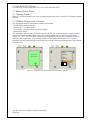
1
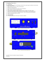
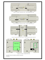
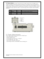
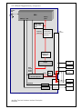
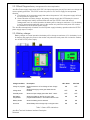
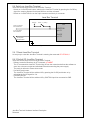
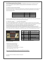
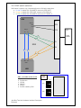
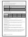
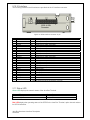
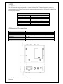
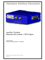
Hardware Interface Description
Java Box Terminal
Motorola G24 Cellular + GPS Engine
Version: 02.01A
Java Box Terminal_HD_V02.01 17.JUL.2008
Java Box Terminal Hardware Interface Description
Released
1. Key Features of the Java Box Terminal
Feature
Implementation
General
Incorporates G24 module
The Motorola G24 module handles all processing for audio, signal and
data within the Java Box Terminal.
Frequency bands
Quad band: GSM 850/900/1800/1900MHz
Power supply
Single supply voltage 6V to 30V
Operating temperature
-20°C to +70°C ambient temperature
Physical
Dimensions: 98mm x 82m x 30m
Weight: 160g , with battery 180g
RoHS, WEEE
All hardware components are fully compliant with the EU RoHS and
WEEE Directives
GSM / GPRS / EDGE features
Data transfer
GPRS
• Multislot Class 10
CSD
• 2.4, 4.8, 9.6 kbps
• USSD
PPP-stack for GPRS data transfer
SMS
• Point-to-point MT and MO
• Text and PDU mode
• Storage: SIM card plus 20 SMS locations in mobile equipment
• Transmission of SMS alternatively over CSD or GPRS.
Preferred mode can be user defined.
Fax
Group 3; Class 1
Audio
Speech codecs:
• Half rate HR
• Full rate FR
• Enhanced full rate EFR
• Adaptive Multi Rate AMR
Line echo cancellation
Software
AT commands
TCP/IP Stack.
Firmware update
AT-Hayes GSM 07.05 and 07.07
TCP/IP stack Access by AT commands
Upgradeable via serial interface / USB
Java Box Terminal Hardware Interface Description
Released
Java Midlet
Major benefits: integration into Java applications, no need for application
microcontroller, extremely cost-efficient hardware and software design –
ideal platform for industrial GSM applications.
The memory space available for Java programs is10.0 MB flash file
system and 1.8 MB RAM. Application code and data share the space in
the flash file system and in RAM.
Interface
Serial interface
• 8-wire modem interface with status and control lines,
unbalanced, asynchronous
• Fixed bit rates: 300 bps to 460,800 bps
• Autobauding: 300 bps to 57,600 bps
• Multiplex ability according to GSM 07.10 Multiplexer Protocol.
I²C
The I²C interface bus for transmission rates up to 100kbps.
Audio
Analog (Microphone amplifier ready, Speaker with 3W amplifier)
2.5mm output audio
SIM interface
Supported SIM cards: 3V
Antenna
Connected via antenna SMA connector or internal antenna
Power on/off, Reset
Power-on
1. Automatic on when power supply turn on ( IGN switch set on )
2. Switch on via On/Off push button
3. On/Off line on IO interface connector
Power-off
Normal switch-off by AT or On/Off push button
Reset
Shutdown and reset by AT command
Special features
GPIO
16 I/O pins of the application interface are programmable as GPIO.
Programming is done via AT commands. Alternatively,
ADC input
3 Analog-to-Digital Converter input for measuring external voltages.
Optional measuring supply voltage to the unit.
Phonebook
SIM and phone
GPS
High sensitivity for indoor reception up to -154 dBm.
Fast TTFF's at low signal levels.
Hot starts less then 2 seconds.
Support 12- Channel GPS.
GPS NMEA 0183 output format.
Java Box Terminal Hardware Interface Description
Released
2. Interface Description
2.1 Overview
Java Box Terminal provides the following connectors for power supply, interface and antennas:
1. On/Off push button.
2. SMA connector (female) for GPS / WiFi antenna.
3. GPRS Led and Power Led.
4. 9-pole (female) SUB-D plug for RS-232 serial interface.
5. SMA connector (female) for GSM antenna.
6. 24-pole GPIO 3mm Micro Mate-N-LOK connector for GPIOs, I²C, ADC, Power.
7. 4-pole 3mm Micro Mate-N-LOK connector for power supply, RTS and Ignition input.
8. 6-pole RJ11 plug (female) for audio accessory, such as a Microphone and Speaker.
9. 8-pole RJ45 plug (female) for UART2
10. USB plug type-B
11. SIM card holder.
12. 2.5mm plug (female) for audio jack, such as a Headset.
5
2
4
3
1
Figure 1: Java Box Terminal front view
7
6
Figure 2: Java Box Terminal side A view
10
9
8
Figure 3: Java Box Terminal side B view
Java Box Terminal Hardware Interface Description
Released
12
DIN rail attachment
Close option
Figure 4: Java Box Terminal rear view 1- DIN rail attachment close
DIN rail attachment
Open option
Figure 5: Java Box Terminal rear view 2 – DIN rail attachment open
DIN rail
attachment
option
Figure 6: Java Box Terminal rear view 3 – DIN rail attachment lock on DIN rail
Battery and SIM
drawer cover
11
2 holes 3mm for
external attachment
Figure 7: Java Box Terminal bottom view
Java Box Terminal Hardware Interface Description
Released
2.2 Block Diagram
Figure 3 shows a block diagram of a sample configuration that incorporates
a Java Box Terminal and typical accessories.
Antenna
GSM
On/Off
Key
SIM
G24
SMA
Antenna
GPS
USB
UART_2
SMA
GPS
GPIO
Audio
Power
USB
PC
UART_1
UART
8 pin
RJ45
USB
B-Type
9 pin
D-Type
Com/
RS232
RS232
No. 1
SW2
3 way
selection
RS232
No. 2
power Led
GPRS Led
Speaker
4 ohm
Audio
24 pin
3w Amp
Speaker
LDO
3.8V
Microphone
GPIO 1-16
Microphone
Battery
Switch
6 pin RJ11
ADC1
ADC2
ADC3
LIPO
Battery
900ma/H
3.7V
Audio
2.5 mm
connector
For Headset
RESET_N
JAVA Reset
IGNITION
Battery
Charger
Option
Input / Output
Power 6-30VDC
Power
DC to DC
5V output
Ground
Input / Output
Power 6-30VDC
To G24
From G24
Input 12v
IGNISTION
Output
RESET_N
4 pin
Figure 8: Block diagram Java Box
Java Box Terminal Hardware Interface Description
Released
24 PIN
70 PIN
G24 OEM /
Connector Pin # Connector Pin # G24-Lite
1
28
GPIO1
2
30
GPIO2
3
32
GPIO3
4
34
GPIO4
5
36
GPIO5
6
38
GPIO6
7
40
GPIO7
8
42
GPIO8
9
41
ANT_DET
10
49
GPRS
11
26
WKUPO_N
12
1
GND
13
23
RI_N
14
13
DSR_N
15
19
DTR_N
16
17
DCD_N
17
16
WKUPI_N
18
37
ADC1
19
43
ADC2
20
47
ADC3
21
25
RESET_N
22
39
TXEN_N
23
51
IGN
24
VIN
Java Box
GPIO1
GPIO2
GPIO3
GPIO4
GPIO5
GPIO6
GPIO7
GPIO8
GPIO9
GPIO10
GPIO11
GND
GPIO12
GPIO13
GPIO14
GPIO15
GPIO16 (JTool)
ADC1
ADC2
ADC3
RESET_N
TXEN_N
IGN
VIN
Table 1: Pin assignment 24 pin connector to 70 pin G24
Java Box Terminal Hardware Interface Description
Released
2.3 Power Supply
The power supply of the Java Box Terminal has to be a single voltage source of POWER 6V-30V
capable of providing a peak during an active transmission. The Java Box Terminal is protected from
supply reversal voltage. An internal fuse ensures an electrical safety according to EN60950. This fuse
is not removable. A fast acting fuse 0.8A with melting is necessary to use with the Java Box Terminal
at a 24V power supply system for vehicles. The power supply must be compliant with the EN60950
guidelines.
Pin
1
2
3
Signal name
POWER
IGNITION
GND
4
RESET_N
Direction
In
In
Out
Use
Input Power supply range 6-30V
Power on console connected to input 12V
Ground
Output notify if modem ON
Table 2: Pin assignment of the plug for power supply and relay
4
3
2
1
Pin assignment
1 – Power
2 – IGNITION
3 – GND
4 – RESET_N
Figure 9: Male 4-pole plug for power supply.
2.3.1 Supply voltage requirements
The DC power supply must be connected to the POWER input:
• Input voltage range 6 - 30V DC
• Nominal Voltage 12V DC
• Power Supply current rating: min. 1,2A @12V
• Power Supply ripple: max. 120mV
• Input current in idle mode: 20mA @ 12V
• Input average current in communication mode: 100mA @ 12V
Java Box Terminal Hardware Interface Description
Released
2.3.2 Block Diagram Battery management
On/Off
Key
G24
RESET_N
Battery
power
IGN
Linear Power
supply output
3.8V
FET
Control switch
5V Power
sense fail
24 pin
Connector
ON when input
power fail
LIPI
Battery 3.7V
900mA/h
Battery
Charger
IGNITION
RESET_N
GPIO
control
DC/DC
Off/On
Enable
Power
5V
DC to DC output 5V
Power
6-30VDC
Polly
Fuse
1.1A
GND
GROUND
IGNITION
Input 12v
IGNITION
Output
RESET_N
4 pin
Figure 9: Block diagram Java Box energy management
Java Box Terminal Hardware Interface Description
Released
2.3.3 Block Diagram Battery management flow chart explanation
Java Box Power supply Input power 6-30 VDC, the input power pass via poly fuse and over voltage and
reverse polarity protection. The DC/DC reduce the power to 5V, the 5V supply for two separate
direction,
A. First direction to Linear power supply that reduce the power to 3.8V, this power supply will hold
the unit power on regular base
B. Second direction to battery charger, the battery charger supply the LIPO battery the correct
power management, battery selected 960ma/H max size 38*39*6.1mm with internal
management card, on normal operation the battery will be charge to maximum 4.1V, the battery
is use for backup and supply the power to the modem only when the main power fail or when
the modem turn off the DC/DC power supply.
The Java Box automatically will switch from linear power supply to battery operation when the DC/DC
power supply stops 5V output.
2.3.4 Battery charger
Battery charger on normal operation the battery will be charge to maximum 4.1V, the battery is use
for backup and supply the power to the modem only when the main power fail or when the modem
turn off the DC/DC power supply.
Charge condition
Charge in progress
Charge done
Description
When the device is in Pre-Charge or fast- Charge
status
When the charging current goes lower than the
IENDTH
LD1- Green
LD2- Red
ON
OFF
OFF
ON
Stand By mode
When the input voltage goes under VBAT - 50mV
OFF
OFF
Bad battery
temperature
When the voltage on the TH pin is out of the
programmable window, in accordance with the NTC
ON
ON
Battery absent
When the battery pack is removed
ON
ON
Over time
When Battery did not charge fully on the given time
ON
ON
Table 3: Status LEDs Indications
Java Box Terminal Hardware Interface Description
Released
2.4 Switch on Java Box Terminal
There are several ways to turn on the Java Box Terminal:
• Switch on via On/Off push button, switch on the Java Box Terminal by pressing the On/Off key
signal line must be asserted for at least 2000 ms and then released.
• Switch on via IGNITION line on the 24pin connector and the 4 pin connector.
Java Box Terminal
Pull Up
SW1 – 1 ( IGN )
G24
24 pin connector
Pin number 23
IGNITION
pin 51
4 pin connector
Pin number 2
On/Off
pin 53
Front panel
On/Off switch
Figure 11: On/Off control
2.4.1 Reset Java Box Terminal
An easy way to reset the Java Box Terminal is entering the command AT+CFUN=0,1
2.4.2 Switch Off Java Box Terminal
There are several ways to turn off the java Box Terminal:
• Software controlled shutdown by AT command: AT+MRST
The AT command lets Java Box Terminal log off from the network and allows the software to
enter into a the secure state and safe data before disconnecting the power supply.
The mode is referred to Power-down mode.
• Via On/Off push button.
The Java Box Terminal will be switched off by pressing the On/Off push button or by
activating the On/Off signal for >2s.
• Via IGNITION line.
The Java Box Terminal will be switched off by IGNITION input line connected to GND.
Java Box Terminal Hardware Interface Description
Released
2.4.3 Disconnecting Power Supply
Before disconnecting the power supply from the POWER pin make sure the Java Box Terminal
is in a safe condition. A safe condition is waiting 2s after the "SHUTDOWN" result code has
been indicated.
2.5 GPIO Interface Specification
All General Purpose input / output are connected to the related pins of the Motorola G24 module over a
100 Ohms series resistor. The following table shows the logic level specifications in the Java Box
terminal interface circuits:
LEVEL
Input high level
Input low level
Output high level
Output low level
MIN
2.0V
0V
2.5V
0V
MAX
3.0V
0.4V
2.8V
0.2V
Table 4: GPIO Signal states level apply to G24 OEM
All GPIO normally HIGH with internal pull up resistor of 22k, to indicate that a LOW signal on the GPIO
connect the GPIO to GND, for HIGH signal leave the GPIO open.
2.6 RS232 number 1__ Interface G24 UART1
The serial interface RS232 number 1 of the Java Box Terminal is intended for the communication
between the GSM module and the host application. This RS232 interface is a data and control interface
for transmitting data, AT commands and providing multiplexed channels. EMC immunity
complies with the vehicular environment requirements according to EN 301 489-7.
The user interface of the Java Box Terminal is accessible from a Data Terminal Equipment DTE
connected to the RS232 interface and it is managed by AT commands according to the GSM 07.07 and
07.05 specification and the supported commands are listed in the AT Commands Reference Guide.
Pin
no.
1
2
3
4
5
6
7
8
9
Figure 12: Pin assignment RS-232
(D-Sub 9-pole female)
Signal name
I/O
Function of application
DCD
RXD
TXD
DTR
GND
DSR
RTS
CTS
RING
O
O
I
I
O
I
O
O
Data Carrier Detected
Receive Data
Transmit Data
Data Terminal Ready
Ground
Data Set Ready
Request To Send
Clear To Send
Ring Indication
Table 5: D-Sub 9-pole female RS232
Connector type on the terminal is:
• RS-232 through D9-pin female
• Baud rate from 300 to 460,600 bit/s
• Autobauding (300 to 57,600 bit/s)
• Short circuit (to Ground) protection on all outputs.
• Input voltage range: -12V to +12V
Note: some of the RRS232 pin as dual use as GPIO, refer to table 1.
Java Box Terminal Hardware Interface Description
Released
2.6.1 The PC as Data Terminal Equipment (DTE)
The software application for using the PC RS232 standard serial interface (COM-port) as Data
Terminal Equipment (DTE) is usually Hyper Terminal. Connect using the COM-port to which the
Java Box Terminal is connected with the following settings:
2.6.2 RS232 number 2__ Interface G24 UART2 or GPS
The serial interface RS232 number 2 of the Java Box Terminal is intended for the communication
between the G24 GSM module UART2 and the host application. This RS-232 interface is a data and
control interface for transmitting data, AT commands and providing multiplexed channels.
Alternative the serial interface RS232 number 2 of the Java Box Terminal can be switch with SW2 to be
connect to the GPS.
Java Box Terminal Hardware Interface Description
Released
2.6.3 SW2 switch selection
SW2 select 3 options, only 2 switches allow to be ON at the same time.
a. S1 and S2 switch ON, G24 UART2 connect to GPS UART.
b. S3 and S4 switch ON, GPS UART connect to PC RS232_2.
c. S5 and S6 switch ON, G24 UART2 connect to PC RS232_2.
G24
RS232
No. 2
UART_2
RTS
RTS
CTS
UART_2
RX
CTS
Com/
RS232
S4
S3
TX
SW2
RX
S1
S2
S6
RX
PC
TX
S5
TX
UART
GPS
SW1 - to enable switch to ON
1. IGN
2. Do Not Use
3. GPIO8
4. WKUP_I
5. GPIO1
6. DC/DC enable by IGN
GPS
Shield
SIM Drawer
ON
OFF
SW1
1
SW2
1
ON
Java Box Terminal Hardware Interface Description
Released
OFF
2.7 Audio Interface
The audio interface provides one analog input for a microphone and one analog output for Speaker.
• The microphone input not balanced.
• The Speaker output is balanced.
• For electret microphone a supply source is implemented by the G24 Modem.
• For speaker 3W amplifier implemented output 4ohm.
123456
Pin assignment
1 – GND
2 - Microphone3 - Speaker 4ohm 3w
4 - Speaker 4ohm 3w
5 - Microphone+
6 - 3.8V
Figure 13: Audio RJ11 plug (6-pole female)
Java Box
6
5
4
3
2
1
RJ11
EAR_HF+
3.8V
3W
AMP
MIC +
Speaker +
Speaker MIC -
EAR_HFMIC_HF+
MIC_HF-
GND
SPKR_N pin 67
SPKR_P pin 69
MIC pin 61
MICN pin 16
Figure 14: Audio block diagram
Sample Commands for Java Box Audio operation
1
2
AT+CLVL=
AT+MMICG=
0-7
0 - 31
Speaker Gain
Microphone Gain
For more Audio command refer to G24 AT command guide page 319
2.7.1 Supported Audio Modes
The audio interface can be configured by inserting the 2.5mm Jack the Audio will be connected to the
Headset, when this jack is out Audio will connected to RJ11 output.
Java Box Terminal Hardware Interface Description
Released
2.7 Antenna Interface
In order to send or receive data connect an external RF antenna to the SMA connector which is
internally connected to the RF signal of the GSM module.
Please consider that the recommended antenna equipment has been chosen to achieve optimum RF
performance when operating the Java Box Terminal.
Frequency range
Bandwidth
Gain
Impedance
Input power
VSWR absolute max
VSWR recommended
Depending by frequency band(s) provided by the network operator, the
customer shall use the most suitable antenna for that/those band(s)
80 MHz in EGSM 900, 70 MHz if GSM 850, 170 MHz in DCS, 140 MHz
PCS band
1.5dBi <= Gain < 3dBi (referenced to isotropic radiator)
50 Ohm
> 2 W peak power
<= 10:1
<= 2:1
Table 6: Antenna speciation
2.8.1 Operating Frequency
The operating frequencies in GSM, DCS, PCS modes are conform to the GSM specifications.
Mode
E-GSM-900
GSM-850
DCS-1800
PCS-1900
Freq. TX (MHz)
890.0 - 914.8
880.2 - 889.8
824.2 – 848.8
1710.2 - 1784.8
1850.2 - 1909.8
Freq. RX (MHz)
935.0 - 959.8
925.2 - 934.8
969.2 – 893.8
1805.2 - 1879.8
1930.2 - 1989.8
Channels (ARFC)
0 – 124
975 - 1023
128 - 251
512 – 885
512 - 810
TX - RX offset
45 MHz
45 MHz
45 MHz
95 MHz
80 MHz
Table 7: Operating frequencies
Transmitter output power
GSM–850 / 900
The Java Box modem in GSM–850/900 operating mode are class 4 in accordance with the
specification which determine the nominal 2W peak RF power (+33dBm) on 50 Ohm.
DCS–1800 / PCS-1900
The Java Box modem in DCS–1800/PCS-1900 operating mode are of class 1 in accordance with the
specifications which determine the nominal 1W peak RF power (+30dBm) on 50 Ohm.
Reference sensitivity
GSM–850 / 900
The sensitivity of the Java Box modem according to the specifications for the class 4
GSM–850/900 portable terminals is –107dBm typical in normal operating conditions.
DCS–1800 / PCS-1900
The sensitivity of the Java Box modem according to the specifications for the class 1
portable terminals DCS-1800 / PCS-1900 is –106 dBm typical in normal operating conditions.
2.9 SIM Interface
The SIM interface is intended for 3V SIM cards. The card holder is a five wire interface according to
GSM 11.11. A sixth pin has been added to detect whether or not the SIM card drawer is inserted.
Removing and inserting the SIM card during operation requires the software to be reinitialized.
Therefore, after reinserting the SIM card it is necessary to restart Java Box Terminal.
Java Box Hardware Interface Description
Released
2.10 IO Interface
The following interfaces and functions are provided via the IO interface connector.
24
13
12
GPIO 24 PIN
Connector
1
Figure 15: GPIO interface connector 24 pin
Pin
1
2
3
4
5
6
7
8
9
10
11
12
13
14
15
16
17
18
19
20
21
22
23
24
Signal name
GPIO1
GPIO2
GPIO3
GPIO4
GPIO5
GPIO6
GPIO7
GPIO8
GPIO9
GPIO10
GPIO11
GND
GPIO12
GPIO13
GPIO14
GPIO15
GPIO16
ADC1
ADC2
ADC3
TXEN_N
JAVA_RESET
IGNITION
VIN
I/O
I/O
I/O
I/O
I/O
I/O
I/O
I/O
I/O
I/O
I/O
I/O
Description
GPIO input or output conferrable
GPIO input or output conferrable
GPIO input or output conferrable
GPIO input or output conferrable
GPIO input or output conferrable
GPIO input or output conferrable
GPIO input or output conferrable
GPIO input or output conferrable
GPIO input or output conferrable
GPIO input or output conferrable
GPIO input or output conferrable
I/O
GPIO input or output conferrable
I/O
GPIO input or output conferrable
I/O
GPIO input or output conferrable
I/O
GPIO input or output conferrable
I/O
GPIO input or output conferrable
I
analog input 1
I
analog input 2
I
analog input 3
O
Modem G24 on or off status
I
Reset Java MIDLET
I
Start Modem
I
Input Power Supply
Table 8: Assignment of the IO interface connector
2.11 Status LED
Green LED displays the network status of the Java Box Terminal.
Green LED status
permanently on
permanently off
Device Status
Unit is active
device off
Table 9: Green LED Status
Red LED displays the operating status of the GPRS in the Java Box Terminal, option internal resistor
for GPIO8 indication.
Java Box Hardware Interface Description
Released
3. GPS
3.1 GPS Antenna Requirements
The GPS module is not provided with an internal LNA amplifier. The use of an active antenna is
important to achieve a good performance. The module is provided of an Antenna supply circuit.
As suggested on the Product Description the external active antenna for a GPS device shall fulfill the
following requirements:
ANTENNA REQUIREMENTS
Frequency range
Bandwidth
Gain
Impedance
Amplification
Supply voltage
Current consumption
1575.42 MHz (GPS L1)
+- 1.023 MHz
1.5 dBi < Gain < 4.5 dBi
50 ohm
Typical 25dB (max 27dB)
Must accept from 3 to 5 V DC
Typical 20 mA (40 mA max)
Table 10: GPS Antenna requirements
4. Mechanical Characteristics
Weight
Dimensions (max) L x W x H
Temperature range
Protection class
Mechanical vibrations Amplitude
Air humidity
Class of flammability
Casing material
160g
98 mm x 82mm x 30mm
-20°C to +70°C ambient temperature
IP40 Avoid exposing JAVA BOX Terminal to liquid or moisture
7.5mm at 5-200Hz sinus
5% - 85%
UL94 HB
PC/ABS Cycoloy 1200 HF
Table 11: Mechanical characteristics
Figure 19: Mechanical measurements
Java Box Terminal Hardware Interface Description
Released
5. ACCSESSORIES
5.1 24 pins Interface Connector
This chapter provides specifications for the 24-pin IO interface connector which serves the GPIO
interfaces of the Terminal. The type of the receptacle assembled on the JAVA BOX Terminal is
24 pin Micro Mate-N-LOK 3mm from MOLEX. Mating headers can be chosen from the MOLEX Micro
Mate-N-LOK Series. For latest product information http://www.molex.com
5.2 Power Supply
This chapter provides specifications for the power supply which serves the Terminal. The power supply
we recommended is 12V 1.2A part number JB12V1.2A. The type of the receptacle assembled on the
JAVA BOX Terminal is 4 pin Micro Mate-N-LOK 3mm from MOLEX. Mating headers can be chosen
from the MOLEX Micro Mate-N-LOK Series. For latest product information http://www.molex.com
5.3 Battery
This chapter provides specifications for the Battery which serves the Terminal. The LIPO battery we
recommended is 3.7V 900mA/h part number JBbattery900 mechanical size 38*39*6.1mm. The type of
the receptacle assembled on the JAVA BOX Terminal is 3 pin Micro Mate-N-LOK 2.0mm from
MOLEX. Mating headers can be chosen from the MOLEX Micro Mate-N-LOK Series. For latest product
information http://www.molex.com
5.4 Power cable
This chapter provides specifications for the power cable which serves the Terminal. The power supply
we recommended is 30V 1.2A part number JBPowerCable. The type of the receptacle assembled on
the JAVA BOX Terminal is 4 pin Micro Mate-N-LOK 3mm from MOLEX. Mating headers can be
chosen from the MOLEX Micro Mate-N-LOK Series. For latest product information
http://www.molex.com
5.5 GSM antenna
This chapter provides specifications for the GSM antennas which serves the Terminal.
We recommended 4 types of GSM antennas with SMA connector:
900/1800Mhz 2.5dBm 3 meter cable part number JBantenna2.5db3M9001800.
850/1900Mhz 2.5dBm 3 meter cable part number JBantenna2.5db3M8501900.
900/1800/1900Mhz 1dBm 5 cm 90 degree SMA part number JBantenna1db5m90018001900SMA.
5.6 GPS antenna
This chapter provides specifications for the GPS antennas which serves the Terminal.
We recommended 2 types of GPS antennas with SMA connector:
1500Mhz 5 meter cable part number GBantennaGPS5m.
5.7 RS232 cable UART 1
This chapter provides specifications for the RS232 Cable UART 1 which serves the Terminal.
We recommended Cable 9 pin D-Type male to female
RS232_1 cable 2 meter cable part number GBrs232Dytpe2m
5.7 RS232 cable UART 2
This chapter provides specifications for the RS232 Cable UART 2 which serves the Terminal.
We recommended Cable RJ45 male to female 9 pin D-Type
RS232_2 cable 1 meter cable part number GBrs232RJ451m
5.7 RJ11 Audio cable
This chapter provides specifications for the AUDIO Cable RJ11 which serves the Terminal.
We recommended Cable RJ11 male to male 6 pin
AUDIO Cable RJ11 20cm meter cable part number GBaudioRJ11m
5.7 USB cable
This chapter provides specifications for the USB Cable which serves the Terminal.
We recommended Cable USB male USB type B to male USB type A
USB Cable 1 meter cable part number GBUSB1m
Java Box Terminal Hardware Interface Description
Released
6. SAFETY RECOMMANDATIONS
READ CAREFULLY
Be sure the use of this product is allowed in the country and in the environment required. The use of
this product may be dangerous and has to be avoided in the following areas:
Where it can interfere with other electronic devices in environments such as hospitals, airports,
aircrafts, etc. Where there is risk of explosion such as gasoline stations, oil refineries, etc
It is responsibility of the user to enforce the country regulation and the specific environment regulation.
Do not disassemble the product; any mark of tampering will compromise the warranty validity. We
recommend following the instructions of the hardware user guides for a correct wiring of the product.
The product has to be supplied with a stabilized voltage source and the wiring has to be conforming to
the security and fire prevention regulations. The product has to be handled with care, avoiding any
contact with the pins because electrostatic discharges may damage the product itself. Same cautions
have to be taken for the SIM, checking carefully the instruction for its use. Do not insert or remove the
SIM when the product is in power saving mode. The system integrator is responsible of the functioning
of the final product; therefore, care has to be taken to the external components of the module, as well
as of any project or installation issue, because the risk of disturbing the GSM network or external
devices or having impact on the security. Should there be any doubt, please refer to the technical
documentation and the regulations in force. Every module has to be equipped with a proper antenna
with specific characteristics. The antenna has to be installed with care in order to avoid any interference
with other electronic devices and has to guarantee a minimum distance from the body (20 cm). In case
of this requirement cannot be satisfied, the system integrator has to assess the final product against the
SAR regulation. The European Community provides some Directives for the electronic equipments
introduced on the market. All the relevant information’s are available on the European Community
website: http://europa.eu.int/comm/enterprise/rtte/dir99-5.htm
The text of the Directive 99/05 regarding telecommunication equipments is available, while the
applicable Directives (Low Voltage and EMC) are available at:
http://europa.eu.int/comm/enterprise/electr_equipment/index_en.htm
Java Box Terminal Hardware Interface Description
Released
7. JAVA BOX GPS Options
This chapter provides options that can be use on the JAVA BOX GPS.
7.1 Battery Source Power
7.1.1 Battery Power
Single 3.7V LIPO cell battery type is use for supplying the power to the JAVA BOX The battery capacity
900mAh.
7.1.2 Battery Charge control Circuitry
The charging process for LIPO Battery divided into 4 phases:
• Qualification and trickle charging
• Fast charge 1 - constant current
• Final charge - constant voltage or pulsed charging
• Maintenance charge
The qualification process down by special internal chip, this chip is battery charger voltage regulator.
moreover all these operations should start only if battery temperature is inside a charging range,
usually 5°C - 45°C. The JAVA BOX measures the temperature of its internal component, in order to
satisfy this last requirement, it's not exactly the same as the battery temperature but in common
application the two temperature should not differ too much and the charging temperature range should
be guaranteed.
Battery and
SIM drawer
Battery
900ma/H
Battery
connector
Figure 20: JAVA BOX Terminal bottom view LIPO Battery location
Java Box Terminal Hardware Interface Description
Released