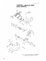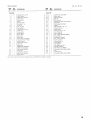
1
Cordless Circular Saw
Equipped with Electric Brake
MODEL 5630DWA
MODEL 5680DWB
With High Capacity Battery Charger
With High Capacity Battery Charger
Blade
diameter
165 m m
(6-1 / 2 " )
Cutting depth
45"
90"
54"
0
10
~
2-1/8")
Battery Cartridge 1 4 2 2
0 - 38"
10
1-1/2")
Net
weight
2,600
364 m m
(14-5116"J
3.2 kg
(7.1 lbsl
Model DC1411 High capacity Battery charger
Input
144V
A.C only 50 H r
Voltage
Overall
length
~
Vo It age
Battery Cartridge 1 4 3 3
No load speed
iRPMi
output
~
60 Hz
D.C. 7.2 V
Charging time
14.4 V
1 Hr.
Model DC1411 High capacity Battery charger
Input
output
~
* Manufacturer reserves t h e r i g h t t o change specifications w i t h o u t n o t i c e
* N o t e Specifications m a y differ f r o m c o u n t r y to c o u n t r y
WARNING For your personal safety, READ and UNDERSTAND before using
SAVE THESE INSTRUCTIONS FOR FUTURE REFESENCE
Charging time
GENERAL SAFETY RULES
(For All Battery Operated Tools)
WARNING! Read and understand all instructions. Failure
t o follow all instructions listed below, may result in electric
shock, fire and/or serious personal injury.
SAVE THESE INSTRUCTIONS
Work Area
Keep your work area clean and well lit. Cluttered benches and dark areas invite
accidents.
Do not operate power tools in explosive atmospheres, such as in the presence
of flammable liquids, gases, or dust. Power tools create sparks which may ignite
the dust or fumes.
Keep bystanders, children, and visitors away while operating a power tool.
Distractions can cause you t o loose control.
Electrical Safety
A battery operated tool with integral batteries or a separate battery pack must
be recharged only w i t h the specified charger for the battery. A charger that
may be suitable for one type of battery may create a risk of fire when used with
another battery.
Use battery operated tool only w i t h specifically designated battery pack. Use
of any other batteries may create a risk of fire.
Personal Safety
Stay alert, watch what you are doing, and use common sense when operating
a power tool. Do not use tool while tired or under the influence of drugs, alcohol,
or medication. A moment of inattention while operating power tools may result
in serious personal injury.
Dress properly. Do not wear loose clothing or jewelry. Contain long hair. Keep
your hair, clothing, and gloves away from moving parts. Loose clothes, jewelry,
or long hair can be caught in moving parts.
Avoid accidental starting. Be sure switch is in the locked or off position before
inserting battery pack. Carrying tools w i t h your finger on the switch or inserting
the battery pack into a tool with the switch on invites accidents.
Remove adjusting keys or switches before turning the tool on. A wrench or
a key that is left attached to a rotating part of the tool may result in personal injury.
Do not overreach. Keep proper footing and balance at all times. Proper footing
and balance enable better control of the tool in unexpected situations.
Use safety equipment. Always wear eye protection. Dust mask, nonskid safety
shoes, hard hat, or hearing protection must be used for appropriate conditions.
2
Tool Use and Care
Use clamps or other practical way t o secure and support the workpiece t o a
stable platform. Holding the work by hand or against your body is unstable and
may lead t o loss of control.
*Do not force tool. Use the correct tool for your application. The correct tool
will do the job better and safer at the rate for which it is designed.
* D o n o t use tool i f switch does not turn it o n or off. A tool that cannot be
controlled with the switch is dangerous and must be repaired.
Disconnect battery pack from tool or place the switch in the locked or off
position before making any adjustments, changing accessories, or storing the
tool. Such preventive safety measures reduce the risk of starting the tool
ac c id e ntaIIy.
Store idle tools out of reach of children and other untrained persons. Tools are
dangerous in the hands of untrained users.
When battery pack is not in use, keep it away from other metal objects like:
paper clips, coins, keys, nails, screws, or other small metal objects that can
make a connection from one terminal t o another. Shorting the battery terminals
together may cause sparks, burns, or a fire.
Maintain tools with care. Keep cutting tools sharp and clean. Properly maintained
tools with sharp cutting edge are less likely t o bind and are easier t o control.
Check for misalignment or binding of moving parts, breakage of parts, and any
other condition that may affect the tool's operation. If damaged, have the tool
serviced before using. Many accidents are caused by poorly maintained tools.
Use only accessories that are recommended by the manufacturer for your
model. Accessories that may be suitable for one tool may create a risk of injury
when used on another tool.
Service
Tool service must be performed only by qualified repair personnel. Service or
maintenance performed by unqualified personnel may result in a risk of injury.
When servicing a tool, use only identical replacement parts. Follow instructions
in the Maintenance section of this manual. Use of unauthorized parts or failure
t o follow Maintenance Instructions may create a risk of shock or injury.
3
Specific Safety Rules
1. DANGER! Keep hands away from cutting area and blade. Keep your second
hand on auxiliary handle, or motor housing. If both hands are holding the
saw, they cannot be cut by the blade.
Keep your body positioned t o either side of the saw blade, but not in line
w i t h the saw blade. KICKBACK could cause the saw t o jump backwards. (See
"Causes and Operator Prevention of Kickback")
Do not reach underneath the work. The guard can not protect you from the
blade below the work. Don't attempt t o remove cut material when blade is
moving .
CAUTION: Blades coast after turn off.
2. Check lower guard for proper closing before each use. Do not operate saw
if lower guard does not move freely and close instantly. Never clamp or tie
the lower guard into the open position. If saw is accidentally dropped, lower
guard may be bent. Raise the lower guard with the Retracting Handle and make
sure it moves freely and does not touch the blade or any other part, in all angles
and depths of cut.
3.Check the operation and condition of the lower guard spring. If the guard
and the spring are not operating properly, they must be serviced before use.
Lower guard may operate sluggishly due t o damaged parts gummy deposits,
or a buildup of debris.
4. Lower guard should be retracted manually only for special cuts such as
"Pocket Cuts" and "Compound Cuts." Raise lower guard by Retracting
Handle. As soon as blade enters the material, lower guard must be released.
For all other sawing, the lower guard should operate automatically.
5. Always observe that the lower guard is covering the blade before placing
saw down on bench or floor. An unprotected, coasting blade will cause the
saw t o walk backwards, cutting whatever is in its path. Be aware of the time
it takes for the blade t o stop after switch is released.
6. NEVER hold piece being cut in your hands or across your leg. It is important
t o support the work properly to minimize body exposure, blade binding, or
loss of control.
7. Hold tool by insulated gripping surfaces when performing an operation where
the cutting tool may contact hidden wiring or its o w n cord. Contact w i t h
a "live" wire will also make exposed metal parts of the tool "live" and shock
the operator.
8. When ripping always use a rip fence or straight edge guide. This improves
the accuracy of cut and reduces the chance for blade binding.
9. Always use blades w i t h correct size and shape (diamond vs. round) arbor
holes. Blades that do not match the mounting hardware of the saw will run
eccentrically, causing loss of control.
IO. Never use damaged or incorrect blade washers or bolts. The blade washers
and bolt were specially designed for your saw, for optimum performance and
safety or operation.
4
11. Causes and Operator Prevention of Kickback:
Kickback is a sudden reaction to a pinched, bound or misaligned saw blade,
causing an uncontrolled saw to lift up and out of the workpiece toward the
operator.
When the blade is pinched or bound tightly by the kerf closing down, the blade
stalls and the motor reaction drives the unit rapidly back toward the operator.
If the blade becomes twisted or misaligned in the cut, the teeth at the back
edge of the blade can dig into the top surface of the wood causing the blade
to climb out of the kerf and jump back toward operator.
Kickback is the result of tool misuse and/or incorrect operating procedures
or conditions and can be avoided by taking proper precautions as given below.
Maintain a firm grip with both hands on the saw and position your body and
arm t o allow you t o resist KICKBACK forces. KICKBACK forces can be
controlled by the operator, if proper precautions are taken.
When blade is binding, or when interrupting a cut for any reason, release
the trigger and hold the saw motionless in the material until the blade comes
t o a complete stop. Never attempt t o remove the saw from the work or pull
the saw backward while the blade is in motion or KICKBACK may occur.
Investigate and take corrective actions t o eliminate the cause of blade binding.
When restarting a saw in the workpiece, center the saw blade in the kerf
and check that saw teeth are not engaged into the material. If saw blade
is binding, it may walk up or KICKBACK from the workpiece as the saw is
restarted.
Support large panels t o minimize the risk of blade pinching and KICKBACK.
Large panels tend t o sag under their o w n weight. Supports must be placed
under the panel on both sides, near the line of cut and near the edge of the
panel as shown in Fig. 1.
To minimize the risk of blade pinching and kickback. When cutting operation
requires the resting of the saw on the work piece, the saw shall be rested
on the laraer Dortion and the smaller ece cut off.
To avoid kickback do support board
or panel near the cut.
Don't support board or panel away
from the cut.
Fig.
'
Fig.
:
5
Do not use dull or damaged blade. Unsharpened or improperly set blades
produce narrow kerf causing excessive friction, blade binding and KICKBACK.
Blade depth and bevel adjusting locking levers must be tight and secure before
making cut. If blade adjustment shifts while cutting, it may cause binding and
KICKBACK.
Use extra caution when making a "Pocket Cut" into existing walls or other
blind areas. The protruding blade may cut objects that can cause KICKBACK.
NEVER place your hand or fingers
behind the saw. If kickback occurs,
the saw could easily jump backwards
over your hand, possibly causing
severe injury.
Fig. 3
12. Adjustments. Before cutting be sure depth and bevel adjustments are tight.
13. Avoid Cutting Nails. Inspect for and remove all nails from lumber before
cutting.
14. When operating the saw, keep the
cord away from the cutting area and
position it so that it will not be caught
on the workpiece during the cutting
operation.
Operate w i t h proper hand support,
proper workpiece support, and
supply cord routing away from the
work area.
A typical illustration of proper hand
support, workpiece support, and
supply cord routing.
Fig. 1
WARN ING :
It is important t o support the workpiece properly and t o hold the saw firmly
t o prevent loss of control which could cause personal injury. Fig. 4 illustrates
typical hand support of the saw.
6
15. Place the wider portion of the saw base o n that part of the workpiece which
is solidly supported, not on the section that will fall off when the cut is made.
As examples, Fig. 5 illustrates the RIGHT way t o cut off the end of a board,
and Fig. 6 the WRONG way. If the workpiece is short or small, clamp it down.
DON'T TRY TO HOLD SHORT PLACES BY HAND!
Fig.
Fig.
circular saw held upside down in a
vise. This is extremely dangerous and
can lead t o serious accidents.
I
Fig.
'
17. Before setting the tool down after completing a cut, be sure that the lower
(telescoping) guard has closed and the blade has come t o a complete stop.
7
SYMBOLS
The followings show the symbols used for tool.
...... volts
................................. amperes
.................................
herts
.................................
kilograms
.................................
minutes
.................................
seconds
.................................
alternating current
.................................
direct current
.................................
no load speed
.................................
alternating or direct current
.................................
Class II Construction
......
splash-proof construction
.................................
watertight construction
.............
revolutions or reciprocation per minute
.................................
number of blow
hours
c-
8
IMPORTANT SAFETY INSTRUCTIONS
FOR CHARGER &
BATTERY CARTRIDGE
1. SAVE THESE INSTRUCTIONS - This manual
Length of Cord (Feet)
25
50
100
150
AWG Size of Cord
18
18
18
16
9
ADDITIONAL SAFETY RULES
FOR CHARGER & BATTERY CARTRIDGE
1. Do n o t charge Battery Cartridge when temperature is BELOW 10°C (50OFI
or ABOVE 4OoC (104OF).
2. Do not attempt t o use a step-up transformer, an engine generator or DC power
receptacle.
3. Do not allow anything t o cover or clog the charger vents.
4. Always cover the battery terminals with the battery cover when the battery
cartridge is not used.
5. A battery short can cause a large current flow, overheating, possible burns
and even a breakdown.
(11 Do not touch the terminals with any conductive material.
(2) Avoid storing battery cartridge in a container with other metal objects such
as nails, coins, etc.
(3)Do n o t expose battery cartridge t o water or rain.
6. Do not store the tool and Battery Cartridge in locations where the temperature may reach or exceed 5OoC (122OF).
7. Do not incinerate the Battery Cartridge even i f it is severely damaged or is
completely worn out. The battery cartridge can explode in a fire.
SAVE THESE INSTRUCTIONS.
10
Installing or removing battery cartridge
*Always switch off the tool before insertion
or removal of the battery cartridge.
*To remove the battery cartridge, withdraw
it from the tool while pressing the buttons
on both sides of the cartridge.
*To insert the battery cartridge, align the
tongue on the battery cartridge with the
groove in the housing and slip it into place.
Always insert it all the way until it locks in
place with a little click. If not, it may accidentally fall out of the tool, causing injury
to you or someone around you.
Fig. 8
*Do not use force when inserting the battery cartridge. If the cartridge does not slide in
easily, it is not being inserted correctly
Charging
*Your new battery cartridge is not charged.
You will need to charge it before use. Use
the high capacity battery charger Model
DC1411 to charge the battery cartridge.
*Plug the high capacity battery charger into
the proper A.C. voltage source. The charging light will flash in green color.
*Insert the battery cartridge so that the plus
and minus terminals on the battery cartridge are on the same sides as their
respective markings on the high capacity
Battery cartridge
Charg'ng'lght
11
*If you charge a battery cartridge from a just-operated tool or a battery cartridge which has
been left in a location exposed to direct sunlight or heat for a long time, the charging light
may flash in red color. If this occurs, wait for a while. Charging will begin after the battery
cartridge cools. The battery cartridge will cool faster if you remove the battery cartridge
from the high capacity battery charger.
*If the charging light flashes alternately in green and red color, a problem exists and charg
ing is not possible. The terminals on the charger or battery cartridge are clogged with
dust or the battery cartridge is worn out or damaged.
Removing or installing the saw blade
CAUTION:
Always be sure that the tool is switched off and the battery cartridge is removed before
installing or removing the blade.
To remove the blade, press the shaft lock
so that the blade cannot revolve and use
the hex wrench to loosen the bolt clockwise. Then remove the bolt, outer flange
and blade.
:wrench
I
I
Fig. 10
To install the blade, follow the removal procedure in reverse.
BE SURE TO TIGHTEN THE BOLT
SECURELY.
Saw blade
Fig. 11
CAUTlON:
*Be sure the blade is installed with teeth pointing up at the front of the tool
*Use only the Makita hex wrench to install or remove the blade.
12
Hex wrench storage
When not in use, the hex wrench can be
conveniently stored.
CAUTION:
Always be sure that the tool is switched off and the battery cartridge is removed before
any adjustment is attempted.
Adjusting depth of cut
Loosen the lever on the depth guide and
move the base up or down.
At the desired depth of cut, secure the base
by tightening the lever.
I
I
CAUTION:
.Use a shallow depth of cut when cutting thin workpiece for cleaner, safer cuts.
*After adjusting the depth of cut, always tighten the lever securely.
Fig. 13
Bevel cutting
Loosen the screw on the bevel scale plate
on the front of the base. Set for desired
angle (0" - 50") by tilting accordingly, then
tighten the clamp screw securely.
I
Bevel scale p l a 4
1
Screw
CAUTION:
After adjusting the depth of cut and bevel cutting angle, be sure to tighten the screw.
Sighting
The front of the base is notched to provide
two guide edges.
For straight cuts, align the edge with 0"
engraved on it with your cutting line on the
workpiece.
For 45" bevel cuts, align the edge with 45"
engraved on it with your cutting line.
For 45" bevel cuts
I
For straight cuts
Cutting line
I
Fig. 17
Switch action
CAUTION:
Before inserting the battery cartridge into the tool, always check to see that the switch
trigger actuates properly and returns to the "OFF" position when released.
To prevent the switch trigger from being
accidentally pulled, a lock-off button is provided.
To start the tool, depress the lock-off button and pull the switch trigger. Release the
switch trigger to stop.
Fig. 18
14
Operation
Hold the tool firmly. Set the base plate on
the workpiece to be cut without the blade
making any contact. Then turn the tool on
and wait until the blade attains full speed.
Now simply move the tool forward over
the workpiece surface, keeping it flat and
advancing smoothly until the sawing is
completed. To get clean cuts, keep your
sawing line straight and your speed of
advance uniform.
Fig. 19
CAUTION:
*Always gently keep the tool moving straight ahead when cutting. Forcing or twisting the
tool will result in overheating of the motor and dangerous kickback, possibly causing
severe injury.
*If the tool is operated continuously until the battery cartridge has discharged, allow the
tool to rest for 15 minutes before proceeding with a fresh battery.
Guide rule
The handy guide rule allows you to do
extra-accurate straight cuts. Simply slide
the guide rule up snugly against the side of
the workpiece and secure it in position with
the clamp screw on the front of the base. It
also makes repeated cuts of uniform width
possible.
Fig. 20
15
MAINTENANCE
CAUTION:
Always be sure that the tool is switched off and the battery cartridge is removed before
attempting to perform inspection or maintenance.
Replacing carbon brushes
Remove and check the carbon brushes regularly. Replace when they wear down to
the limit mark. Keep the carbon brushes
clean and free to slip in the holders. Both
carbon brushes should be replaced at the
same time. Use only identical carbon
brushes.
Limit mark
I
I
I
Fig. 21
Use a screwdriver to remove the brush
holder caps. Take out the worn carbon
brushes, insert the new ones and secure
the brush holder caps.
Fig. 22
To maintain product SAFETY and RELIABILITY, repairs, maintenance or adjustment should
be performed by Makita Authorized or Factory Service Centers, always using Makita
replacement parts.
Trickle charge (Maintenance charge)
If you leave the battery cartridge in the charger to prevent spontaneous discharging after
full charge, the charger will switch into its "trickle charge (maintenance charge)" mode
and keep the battery cartridge fresh and fully charged.
Tips for maintaining maximum battery life
1. Charge the battery cartridge before completely discharged.
Always stop tool operation and charge the battery cartridge when you notice less tool
power.
2. Never recharge a fully charged battery cartridge.
Overcharging shortens the battery service life.
3. Charge the battery cartridge with room temperature at 10°C - 40°C (50°F
Let a hot battery cartridge cool down before charging it.
16
- 104°F).
Recycling the Battery
The only way to dispose of a Makita battery is
to recycle it. The law prohibits any other
method of disposal.
Ni-Cd
To recycle the battery:
1. Remove the battery from the tool.
2. a). Take the battery to your nearest Makita Factory Service Center
or
b). Take the battery to your nearest Makita Authorized Service Center or
Distributor that has been designated as a Makita battery recycling location.
Gall your nearest Makita Service Center or Distributor to determine the location
that provides Makita battery recycling. See your local Yellow Pages under
"Tools-€lectric':
ACCESSORIES
CAUTION
These accessories or attachments are recommended for use with your Makita tool specified in this
manual The use of any other accessories or attachments might present a risk of inlury t o persons
The accessories or attachments should be used only in the proper and intended manner
High capacity battery charger DC1411
High capacity battery 142211433
Part No 192700-7
1422
1433
Battery cover
Hex wrench
Part No. 783203-8
Part No.414938-7
Tungsten carbide tipped saw blade
For wood
Part
No
726008-3
- Part No
- Part No
192600-1
192699-6
Hole diameter
(mm)
No teeth
(mm)
165 (6-1/2")
15 88 (5/8")
24
Diameter
Feb-04--'99 US
CORDLESS CIRCULAR SAW
Model 5630DW
e-59
Note: The switch and other part ConfigUratlOnS
may differ from country to Country.
18
Feb-04-'99
MODEL 5630DW
I:","
GtD
MACHINE
MACHINE
~
1
2
3
4
5
6
7
8
9
10
11
12
13
14
15
16
17
18
19
20
21
22
23
24
25
6
1
1
1
1
1
1
1
1
1
1
2
2
2
1
1
Tapping Screw 4x18
Switch Button
1
1
3
Rpar Cover
26
21
28
29
30
1
1
1
1
1
1
1
DESCRIPTION
DESCRIPTION
~
2
1
1
1
US
Compresslo" Spring 4
Handle Cover
Switch Lever
Switch
Battery Holder
Stop Ring E - 8
Lever 40
Hex N u t M 6
Flat Washer 6
Tapping Screw 4x18
Holder Cap
Carbon Brush
35
36
31
38
39
40
41
42
1
1
2
1
1
1
1
1
1
Brush Holder
Brush Holder
Name Plate
Pan Head Screw M5x40
Tapping Screw M i 4x60
Motor Housing
Ball Bearing 627LLB
Yoke Unit
Baffle Plate
ARMATURE ASSEMBLY
(With Item 22 & 261
Ball Bearing 6000LLB
Shaft Lock
Compresslo" Spring 5
Blade Case Complete
Rubber Rina 6
Countersunk Screw M 6
Makita Label
Ball Bearing 606
Ring 12
Spur Gear 53
Countersunk Head Screw M5x16
Bearing Box
Ball Bearing 6201DDW
Spindle
Bearing Retainer 1 9 - 3 3
Tension Spring 3
Safety Cover
Retaining Ring S 38
Inner Flange 40
Outer Flange 40
Hex Socket Head Bolt M6x20
Screw M6x14
compress,on s p m g 7
Hex Lock N u t M 5 - 8
Depth Complele
S p m q Washer 6
Screw M6x14
Flat Washer 6
Pan Head Screw M 5
Angular Complete
Flat Hpad Srraw M6x90
Countersunk Head Screw M4x8
Base
Screw M5x12
Countersunk Head Screw M5x8
Note The switch and other part specificdtions may differ from country to country
19
1
MAKITA LIMITED ONE YEAR WARRANTY
Warranty Policy
Every Makita tool is thoroughly inspected and tested before leaving the factory. It is warranted to
be free of defects from workmanship and materials for the period of ONE YEAR from the date of
original purchase. Should any trouble develop during this one-year period, return the COMPLETE
tool, freight prepaid, to one of Makita’s Factory or Authorized Service Centers. If inspection shows
the trouble is caused by defective workmanship or material, Makita will repair (or at our option,
replace) without charge.
II
This Warranty does not apply where:
repairs have been made or attempted by others:
repairs are required because of normal wear and tear:
The tool has been abused, misused or improperly maintained;
alterations have been made to the tool.
IN NO EVENT SHALL MAKITA BE LIABLE FOR ANY INDIRECT, INCIDENTAL OR CONSEQUENTIAL DAMAGES FROM THE SALE OR USE O F THE PRODUCT. THIS DISCLAIMER
APPLIES BOTH DURING AND AFTER THE TERM OF THIS WARRANTY.
MAKITA DISCLAIMS LIABILITY FOR ANY IMPLIED WARRANTIES, INCLUDING IMPLIED
WARRANTIES O F “MERCHANTABILITY” AND “FITNESS FOR A SPECIFIC PURPOSE.’’
AFTER THE ONE-YEAR TERM OF THIS WARRANTY.
This Warranty gives you specific legal rights, and you may also have other rights which vary from
state to state. Some states do not allow the exclusion or limitation of incidental or consequential
damages, so the above limitation or exclusion may not apply to you. Some states do not allow
limitation on how long an implied warranty lasts, so the above limitation may not apply to you.
i
__cu
Makita Corporation of America
2650 Buford Hwy., Buford, GA 30518
884232-067
PRINTED IN USA
1999-2-
N