1
Owner's Manual
(RI:IFTSMI:IN"
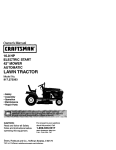
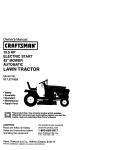
24.0 HP
ELECTRIC START
50" MOWER
AUTOMATIC
GARDEN TRAC'I' R
Model No.
917.273220
•
•
•
•
Safety
Assembly
Operation
Maintenance
• Repair Parts
CAUTION:
For answers to your questions
about this product, Call:
Read and follow all
Safety Rules and Instructions
before operating this equipment,
Sears,
Roebuck.and
1-800-659-5917
Sears Craftsman Help Line
5 am- 5 pro, Mon- Sat
Co., Hoffman Estates,
IL 60179
Maintenance .........................................
19
Service and Adjustments ...................... 23
Storage .................................................
31
Troubleshooting ....................................
32
Repair Parts .........................................
36
Parts Ordering ....................... Back Cover
RIDING
EQUIPMENT
if this Craftsman Riding Equipment is mainto the instructions in the owner's manual,
any parts found to be defective in material or
Sears
This
• Expendable _ems which I_ecome wom during normal use, such as blades, spark
plugs, air cleaners, belts, etc. i
• Tire replacement or repair caused by punctures from outside objects, such as nails,
thorns, stumps, or glass.
• Repairs necessary because of operator abuse, negligence, improper storage or accident or the failure to maintain the equipment according to the instructions contained in
the owner's manual.
• Riding equipment used for commercial or rental purposes.
LIMITED 90 DAY WARRANTY ON BATTERY
For ninety (90) days from date of purchase, if any battery included with this riding equipment proves defective in material or workmanship and our testing determines the battery will not hold a charge, Sears will replace the battery at no charge. In-home warranty
service on your Craftsman riding equipment is available at no charge for 30 days from
the date of purchasa. Please contact your nearest service center. After 30 days from the
date of purchase, warranty service is available by taking your Craftsman riding equipment to your nearest Sears Service Center. (In-home warranty service will still be available after 30 days from the date of purchasa but a standard trip charge will apply). This
warranty applies only while this product is in the United States. This Warranty gives you
specific legal rights, and you may also have other rights which may vary from state to
state.
Sears, Roebuck and Co., D/817 WA, Hoftman Estates, IL 60179
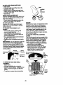
GENERAL
OPERATION
• Read, understand, and follow all instructions in the manual and on the machine
before starting.
• Only allow responsible adults, who are
familiar with the instructions, to operate
the machine.
• Clear the area of objects such as rocks,
toys, wire, etc., which could be picked
up and thrown by the blade.
• Be sure the area is clear of other people
before mowing. Stop machine if anyone
enters the area.
• Never carry passengers.
• Do not mow in reverse unless absolutely necessary. Always look down and
behind before and while backing.
• Be aware of the mower discharge direction and do not point it at anyone. Do
not operate the mower without either
the entire grass catcher or the guard in
place.
• Slow down before turning.
• Never leave a running machine unattended. Always turn off blades, set parking brake, stop engine, and remove
key_ before dismounting.
• Turnoff blades
when not mowing.
• Stop engine before removing grass
catcher or unclogging chute.
• Mow only in daylight or good artificial
• Do nottry to stabilize the machine by
putting your foot on the ground.
• Do not use grass catcher on steep
slopes.
light.
• Do not operate the machine while under
the influence of alcohol or drugs.
• Watch for traffic when operating near or
crossing roadways.
• Use extra care when loading or unload-
CHILDREN
ing the machine into a trailer or truck.
SLOPE
OPERATION
Slopes are a ma}or factor related to lossof-control and tipover accidents, which
can result in severe injury or death. All
slopes require extra caution. If you cannot
back up the slope or if you feel uneasy on
it, do not mow it.
DO:
• Mow up and down slopes, not across.
• Remove obstacles such as rocks, tree
limbs, etc.
• Watch for holes, ruts, or bumps. Uneven
terrain could overturn the machine. Tall
grass can hide obstacles.
• Use slow speed. Choose a low gear so
that you will not have to stop or shift
while on the slope.
• Follow the manufacturer's recommendations for wheel weights or counterweights to improve stability.
• Use extra care with grass catchers or
other attachments. These can change
the stability of the machine.
• Keep all movement on the slopes slow
and gradual. Do not make sudden
changes in speed or direction.
• Avoid starting or stopping on a slope. If
tires lose traction, disengage the blades
and proceed slowly straight down the
slope.
DO NOT:
• Do nottum on slopes unless necessary,
and then, turn slowly and gradually
downhill, if possible.
• Do not mow near drop-offs, ditches, or
embankments.
The mower could suddenly turn over if a wheel is over the
edge of a cliff or ditch, or if an edge
caves in.
• Do not mow on wet grass. Reduced
traction could cause sliding.
Tragic accidents can occur if the operator
is not alert to the presence of children.
Children are often attracted to the
machine and the mowing activity. Never
assume that children will remain where
you last saw them.
• Keep children out of the mowing area
and under the watchful care of another
responsible adult.
• Be alert and turn machine off if children
enter the area.
• Before and when backing, look behind
and down for small children.
• Never carry children. They may fall off
and be seriously injured or intedere with
safe machine operation.
• Never allow children to operate the
machine.
• Use extra care when approaching blind
corners, shrubs, trees, or other objects
that may obscure vision.
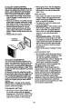
SERVICE
• Use extra care in handling gasoline and
other fuels. They are flammable and
vapors are explosive.
Use only an approved container.
Never remove gas cap or add fuel
with the engine running. Allow engine to cool before refueling. Do not
smoke.
Never refuel the machine indoors.
Never store the machine or fuel
container inside where there is an
open flame, such as a water heater.
• Never run a machine inside a closed
area.
• Keep nuts and bolts, especially blade
attachment bolts, tight and keep equipment in good condition.
• Never tamper with safety devices.
Check their proper operation regularly.
• Keep machine free of grass, leaves, or
other debris build-up.. Clean oil or fuel
spillage. Allow machine to cool before
storing.
• Stop and inspect the equipment if you
strike an object. Repair, if necessary,
before restarting.
• Never make adjustments or repairs with
the engine running.
• Grass catcher components are subject
to wear, damage, and deterioration,
which could expose moving parts or
allow objects to be thrown. Frequently
check components and replace with
manufacturer's recommended parts,
when necessary.
• Mower blades are sharp and can cut.
• Be sure the area is clear of other people
before mowing. Stop machine if anyone
enters the area.
• Mow up and down slopes (15 ° Max), not
across.
• Remove obstacles such as rocks, tree
limbs, etc.
• Watch for holes, ruts, or bumps. Uneven
terrain could overturn the machine. Taft
Wrap the blade(s) or wear gloves, and
use extra caution when servicing them.
• Check brake operation frequently.
Adjust and service as required.
• Never carry passengers.
• Do not mow in reverse unless absolutely necessary. Always look down and
behind before and while backing.
• Never carry children. They may fail off
and be seriously injured or interfere with
safe machine operation.
• Keep children out of the mowing area
and under the watchful care of another
grass can hide obstacles.
• Use slow speed. Choose a low gear so
that you will not have to stop or shift
while on the slope.
• Avoid starting or stopping on a slope. If
tires lose traction, disengage the blades
and proceed slowly straight down the
slope.
• Do notturn on slopes unless necessary,
and then, turn slowly and gradually
downhill, if possible.
responsible adult.
, Be alert and turn machine off if children
enter the area.
• Before and when backing, look behind
and down for small children.
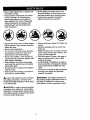
_,WARNING:
_,Look
for this symbol to point out important safety precautions. It means CAUTION!!! BECOME AWARE!I! YOUR SAFETY IS INVOLVED.
The engine exhaust from
this product contains chemicals known to
the State of California to cause cancer,
birth defects, or other reproductive harm.
,_.CAIJTiON:
In order to prevent accidental starting when setting up, transporting,
adjusting or making repairs always disconnect spark plug wire and place wire where
it cannot contact spark plug.
4
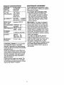
PRODUCT SPECIFICATIONS
MAINTENANCE
GASOLINE
CAPACITY
AND TYPE:
3.5 GALLONS
UNLEADED
REGULAR
A Sears Maintenance Agreement is available on this product. Contact your nearest
Sears store for details.
OIL TYPE
_,PI-SF/SG/SH):
SAE 10W-30
(above 32°F)
SAE 5W-30
CUSTOMER
W/FILTER:
W/O FILTER:
4.2 PINTS
3.7 PINTS
SPARK PLUG:
Champion RC12YC
(GAP: .040")
GROUND SPEED FORWARD: 5.8
(MPH):
TIRE PRESSURE:
CHARGING
SYSTEM:
BAI-FERY:
BLADE BOLT
TORQUE:
REVERSE:
2.1
FRONT: 14 PSI
REAR: 10 PSI
15AMPS@
RESPONSIBIUTIES
• Read and observe the safety rules.
• Follow a regular schedule in maintaining, caring for and using your tractor.
• Follow the instructions under "Mainte-
(below 32°F)
Z)IL CAPACITY:
AGREEMENT
3600 RPM
AMP/HR:
35
MIN. CCA:
280
CASE SIZE: U1R
nance" and "Storage"
owner's manual.
sections of this
_,WARNING:
This tractor is equipped
with an internal combustion engine and
should not be used on or near any unimproved forest-covered, brush-covered or
grass-covered land unless the engine's
exhaust system is equipped with a spark
arrester meeting applicable local or state
laws (if any). If a spark arrester is used, it
should be maintained in effective working
order by the operator.
In the state of California the above is
required by law (Section 4442 of the
California Public Resources Code). Other
states may have similar laws. Federal
laws apply on federal lands. A spark
arrester for the muffler is available through
your nearest Sears Authorized Service
Center (See REPAIR PARTS section of
this manual).
27-35 FT. LBS.
CONGRATULATIONS
on your purchase
of a Craftsman Tractor. It has been
designed, engineered and manufactured
to give you the best possible dependability
and performance.
Should you experience any problem you
cannot easily remedy, please contact your
nearest Sears Authorized Service Center.
We have competent, welt-trained technicians and the proper tools to service or
repair this tractor.
Please read and retain this manual. The
instructions will enable you to assemble
and maintain your tractor properly. Always
observe the =SAFETY RULES".
5
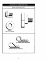
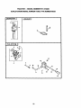
PartsBagcontentsshownfull
size
(1) Knob
(1) Shoulder
Bolt 5/16-18
@
(1) Washer
17/32 x 1,.3/16 x 12 Gauge
a'ner Springs
I
(4) Retainer Springs (single loop)
6
(double loop)
Parts packet separately in carton
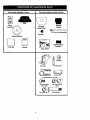
Parts Bag contents not shown full size
D
Seat
Video
Steedng
Sleeve
Steering
Wheel Insed
'_
Cassett_
_(2)
Front Unk Assemblies
(2) Keys
Steedng Wheel
"r
;
i
i
]
:
SteedngSleeve
Extension
,
Parts Bag
_L
Manual
Slope Sheet
(4) Wheels
(4) Brackets
(12) Gardage Bolts
5/16-18 x 5/8
_4) AdjustingBar
(12) CrownlockNuts
3/8-16
m
(4) Locknut 3/8-16
7
(4) Shoulder Bolt
I
Yournewtractorhasbeenassembledatthe factorywith exception
of those parts left
unassembled for shipping purposes. To ensure safe and proper operation of your tractor
all parts and hardware you assemble must be tightened securely. Use the correct tools
as necessary to insure proper tightness. Review the video cassette before you begin.
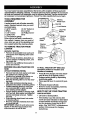
TOOLS REQUIRED FOR
ASSEMBLY
-- Wheel Insert
A socket wrench set will make assembly
easier. Standard wrench sizes you need
are listed below.
_.Hex
Lock Washer
(1) 9/16" wrench
(1) 3/4" Socket w/
(1)Pliers
drive rachet
(1) 1/2" wrench
(1) Phillips Screw(1) Utility knife
driver
(1) Tire pressure gauge
When right or left hand is mentioned in
this manual, it means, from your point of
view, when you are in the operating position (seated behind the steering wheel).
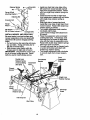
TO REMOVE
CARTON
TRACTOR
Large Flat
Washer
Steering
Steering
Wheel
Steering _
Sleeve _
Extension
FROM
UNPACK CARTON
• Remove all accessible loose parts and
parts boxes from shipping carton (See
page 6).
• Cut, from top to bottom, along lines on
all four comers of shipping carton, and
lay panels flat.
• Check for any additional loose pads or
boxes and remove.
BEFORE
ROLLING
SKID
ATTACH STEERING
TRACTOR
Bolt
Wheel
Adapter
Tabs
_
Shaft
Steering
Sleeve
OFF
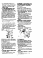
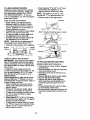
TO ROLL TRACTOR OFF SKID (See
Operation section for location and
function of controls)
WHEEL
• Remove hex bolt, lock washer and large
flat washer from steering shaft.
• Position front wheels of the tractor so
they are pointing straight forward.
• Slide the steering sleeve over the steering shaft.
• Align tabs and press steering sleeve
extension into bottom of steering wheel.
• Position steering wheel so cross bars
are horizontal (left to right) and slide
onto steedng wheel adapter.
• Secqre steering wheel to steedng shaft
with hex bolt, lock washer and large flat
washer previolJsly removed. Tighten
securely.
"
• Snap steering wheel insert into center
of steedng wheel.
• Remove protective materials from tractor hood ahd grill.
IMPORTANT: Check for and remove any
staples in skid that may puncture tires
where tractor is to roll offskid.
• Press lift lever plunger and raise attachment lift lever to its highest position.
• Release parking brake by depressing
clutch/brake pedal.
• Place gearshift lever in neutral (N) position.
• Roll tractor forward off skid.
• Remove mower and packing materials.
• Remove ties from V-belts.
HOW TO SET UP YOUR TRACTOR
CHECK BA'I'rERY
• Lift hood to raised position.
• If this battery is put into service after
month and year indicated on label (label
located between terminals) charge battery for minimum of one hour at 6-10
amps. (See "BATTERY" in Maintenance
section of this manual for charging
instructions).
8
°_ :_2;"
_"
.°"
e.4
•
ASSEMBLE
BRACKETS
•
o_
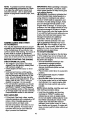
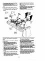
The gauge wheels are designed to keep
the mower deck in proper position when
operating mower. Be sure they are properly adjusted to ensure optimum mower performance.
I
• Attach front gauge wheel brackets
marked front left (FL), front right (FR)
to mower deck using (3) carriage bolts
and (3) Iocknuts. For ease of installation
do not tighten Iocknuts until all carriage
belts have been installed.
Label"
J
INSTALL
GAUGE WHEELS AND
TO MOWER DECK
SEAT
• Attach rear gauge wheel brackets
marked rear left (R L), rear right (RR) to
mower deck using (3) carriage bolts and
(3) Iocknuts. For ease of installation do
not tighten Iocknuts until all carriage
bolts have been installed.
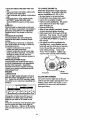
Adjust seat before tightening adjustment
knob.
• Remove cardboard packing on seat
pan.
• Place seat on seat pan and assemble
shoulder bolt. Tighten shoulder bolt
securely.
• Assemble adjustment knob and fiat
washer loosely. Do not tighten.
• Lower seat into operating position and
sit on seat.
• Slide seat until a comfortable position is
reached which allows you to press
clutch/brake pedal all the way down.
• Get off seat without moving its adjusted
position.
• Raise seat and tighten adjustment knob
securely.
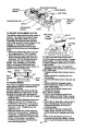
• Slide gauge wheel bar down into bracket channel, Be sure that gauge wheel
bar aligning holes are on top. Assemble
gauge wheels as shown using shoulder
bolts, 318 washers and 3/8-16 center
Iocknuts and tighten securely.
• Adjust gauge wheels to highest position
for ease of mower deck assembly.
• Adjust gauge wheels before operating
mower as shown in the operation section of this manual.
Seat
Retainer _
Seat Pan
Shoulder
Bolt
_.Crownlock
rNuts
Gauge Wheel
Mounting
Adjusting Bar
Adjustment
Knob
Shoulder Bolt
Flat Washer
CHECK
Gauge
TIRE PRESSURE
The tires on your tractor were ovednflated
at the factory for shipping purposes.
Correct tire pressure is important for best
cutting performance.
• Reduce tire pressure to PSI shown in
=PRODUCT SPECIFICATIONS"
on
3/8-16 q
page 5 of this manual.
CHECK
BRAKE
SYSTEM
After you leam how to operate your tractor, check to see that the brake is properly
adjusted. See "1"O ADJUST BRAKE" in
the Service and Adjustments section of
this manual.
9
CamageBolts
Retainer
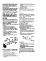
• Install one front link in top hole of the
left hand front mower bracket and left
hand front suspension bracket. Retain
with two single loop retainer springs as
shown.
• Install second front link in right hand
front suspension bracket only and retain
with single loop retainer spnng as
shown.
• Slide right side of mower back and
install link in top hole of dght hand front
mower bracket. Retain with single loop
retainer spring as shown.
rCrownlock
Nuts
Pin
Gauge Wheel
Mounting
Adjusting Bar
Shoulder Bolt
Gauge
3/8
clockwise
it stops. knob counterurn heightuntil
adjustment
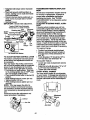
Lower mower linkage with attachment
lift control.
• Place the suspension arms on inward
pointing deck pins. If necessary, rock
and raise front of mower to all,in deck
pins with the holes in suspenston arms.
Retain with double loop retainer springs
with loops down as shown.
• Connect anti-sway bar to chassis bracket under left footrest and retain with
double loop retainer spring.
•Tum
height adjustment knob clockwise
to remove slack from mower suspension.
i
Carriage Bolts
INSTALL MOWER AND DRIVE BELT
Be sure tractor is on level surface and
mower suspension arms are raised with
attachment lift control. Engage parking
brake.
• Cut and remove ties securing anti-sway
bar and belts. Swing anti-sway bar to
left side of mower deck.
• Slide mower under tractor with discharge guard to right side of tractor.
IMPORTANT:
Check belt for proper routing in all mower pulley grooves. Install
belt into electric clutch pulley groove.
Double Loop
Retainer Spdng
deck pins)
Front Mower
Bracket
Front
Suspension
Brackets
Suspension
Arms
Front Link
Chassis
Single Loop
Retainer Springs
-Gauge
Wheel
Double Loop
Retainer Spring
Discharge
Guard
Anti-Sway Bar
Idler Pulley
lO
Raisedeckto highestposition.
Adjustgaugewheelsbeforeoperating
moweras shownin the Operationsectionof this manual.
CHECKMOWERLEVELNESS
Forbest cuffingresults,mowershouldbe
properlyleveled. See =TO LEVEL
MOWER
HOUSING"
in the Service and
Adjustments section of this manual.
CHECK FOR PROPER
ALL BELTS
POSITION
OF
See the figures that are shown for replacing motion, mower drive, and mower blade
drive belts in the Service and Adjustments
section of this manual. Verify that the
belts are routed correctly.
CHECKLIST
Please review the following checldist:
,/ All assembly instructions have been
completed.
,/No remaining loose parts in carton.
/ Battery is properly prepared and
charged. (Minimum 1 hour at 6 amps).
,/Seat is adjusted comfortably and tightened securely.
,/All tires are properly inflated. (For shipping purposes, the tires were overinflated at the factory).
,/Be sure mower deck is propedy leveled
side-to-side/front-to-rear
for best cutting
results. (Tires must be propedy inflated
for leveling).
,/Check
mower and drive belts. Be sure
they are muted properly around pulleys
and inside all belt keepers.
,/Check wiring. See that all connections
are still secure and wires are properly
clamped.
/ Before driving tractor, be sure freewheel
control is in drive position.
While learning how to use your tractor,
pay extra attention to the following important items:
/ Engine oil is at proper level.
,/Fuel tank is filled with fresh, clean, regular unleaded gasoline.
/ Become familiar with all controls - their
location and function.
Operate them
before you start the engine.
/ Be sure brake system is in safe operating condition.
,/It is important to purge the transmission
before operating your tractor for the first
time. Follow proper starting and transmission purging instructions (See =TO
START ENGINE" and =PURGE TRANSMISSION" in the Operation section of
this manual).
11
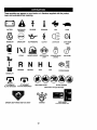
These symbols may appear on your tractor or in literature supplied with the product.
Leam and understand their meaning.
BATTERY
CAUTION OR
WARNING
REVERSE
FORWARD
FAST
SLOW
ENGINE ON
ENGINE OFF
OIL PRESSURE
CLUTCH
LIGHTS ON
OVER TEMP
LIGHT
CHOKE
MOWER HEIGHT
DIFFERENTIAL
PARKING BRAKE
UNLOCKED
FUEL
LOCK
I
LOCKED
R
N
H
k
REVERSE
NEUTRAL
HIGH
LOW
PARKING BRAKE
MOWER UFT
ATTACHMENT
CLUTCH ENGAGED
ATTACHMENT
CLUTCH DISENGAGED
KEEP AREA CLEAR
SLOPE HAZARDS
(SEE SAFETY RULES SECTION)
DANGER, KEEP HANDS AND FEET AWAY
IGNITION
12
FREE WHEEL
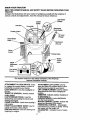
KNOW YOUR TRACTOR
READ THIS OWNER'S MANUAL AND SAFETY RULES BEFORE OPERATING YOUR
TRACTOR
Compare the illustrationswith your tractor to familiarize yourself with the locations of
various controls and adjustments. Save this manual for future reference.
Ignition
Switch
Light Switch
Position
Hourmeter
Attachment
Clutch Switch
Throttle Control
Lift Lever
Plunger
Clutch/Brake
Lift Lever
Control
- Parking Brake
Motion
Control
Lever
Height
Adjustment
Knob
Free Wheel
Our tractors conform to the safety standards of the American
National Standards Institute.
ATTACHMENT
CLUTCH SWITCH: Used
to engage the mower blades, or other attachments mounted to your tractor,
LIGHT SWITCH: Turns the headlights on
and off.
THROTTLE
CONTROL: Used to control
engine speed.
CLUTCH/BRAKE
PEDAL: Used for
declutching and braking the tractor and
starting the engine.
CHOKE CONTROL: Used when starting a
cold engine.
HEIGHT ADJUSTMENT
KNOB: Used to
adjust the mower cutting height.
IGNITION SWITCH: Used for starting and
stopping the engine.
ATTACHMENT
LIFT LEVER: Used to
raise and lower the mower deck or other
attachments mounted to your tractor.
LIFT LEVER PLUNGER: Used to release
attachment lift lever when changing its
position.
AMMETER:
Indicates battery charging (+)
or discharging (-).
PARKING BRAKE: Locks clutch/brake
into the brake position.
MOTION CONTROL LEVER - Selects the
speed and direction of the tractor.
FREEWHEEL
CONTROL - Disengages
transmission for pushing or slowly towing
the tractor with the engine off.
HOURMETER
- Indicates hours of operation
17
The operation of any tractor can result in foreign objects thrown into the
eyes, which can result in severe eye damage. Always wear safety glasses
or eye shields while operating your tractor or performing any adjustments or
repairs. We recommend a wide vision safety mask over spectacles, or standard safety glasses.
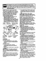
HOW
TO USE YOUR
TRACTOR
• Turn ignition key to "OFP position and
remove key. Always remove key when
leaving tractor to prevent unauthorized
use.
• Never use choke to stop engine.
IMPORTANT: Leaving the ignition switch
in any position other than "OFF' will cause
the battery to be discharged (dead).
NOTE: Under certain conditions when
tractor is standing idle with the engine running, hot engine exhaust gases may
cause "browning" of grass. To eliminate
this possibility, always stop engine when
stopping tractor on grass areas.
_, CAUTION." Always stop tractor completely, as described above, before leaving
the operator's position; to empty grass
catcher, etc.
THROTTLE CONTROL
Your tractor is equipped with an operator
presence sensing switch. When engine is
running, any attempt by the operator to
leave the seat without first setting the
parking brake will shut off the engine.
TO SET PARKING BRAKE
• Depress,clutch/brake
pedal into full
=BRAKE" position and hold.
• Place parking brake lever in "ENGAGED" position and release pressure
from clutch/brake pedal. Pedal should
remain in =BRAKE" position. Make sure
parking brake will hold tractor secure.
Throttle
Control
...... \
Push-In to
=Disengaged"
Attachment Clutch
Switch Pull Out To
_
"Engage"_
Always operate engine at full throttle.
• Operating engine at less than full throttle reduces the battery charging rate.
• Full throttle offers the best bagging and
mower performance.
CHOKE CONTROL
Pedal Drive
Position
Position
STOPPING
MOWER BLADES
Use choke control whenever you are starting a cold engine. Do not use to start a
warm engine.
• To engage choke control, pull knob out.
Slowly push knob in to disengage.
TO MOVE FORWARD AND BACKWARD
u u
Position
The direction and speed of movement is
controlled by the motion control lever.
• Start tractor with motion control lever in
neutral (N) position.
• Release parking brake and clutch/brake
pedal.
• Slowly move motion control lever to
desired position.
TO ADJUST MOWER CUTTING HEIGHT
-
• To stop mower blades, move attachment clutch switch to "DISENGAGED"
position.
GROUND DRIVE • To stop ground drive, depress
clutch/brake pedal into full "BRAKE"
position.
• Move motion control lever to neutral (N)
position.
IMPORTANT:
The motion control lever
does not retum to neutral (N) position
when the clutch/brake pedal is depressed.
ENGINE -
The cutting height is controlled by turning the height adjustment
knob in
desired direction.
•Tum
knob clockwise (G) to raise cutting
height.
.
• Turn knoo counterclockwise (_)to
lower cutting height.
The cutting height range is approximately
1-1/2" to 4-1/2". The heights are measured from the ground to the blade tip with
the engine not running. These heights are
approximate and may vary depending
upon soil conditions, height of grass and
types of grass being mowed.
• Move throttle control to slow position.
NOTE: Failure to move throttle control to
slow position and allowing engine to idle
before stoppingmay cause engine to
"backfire".
14
• The average lawn should be cut to
approximately 2-1/2 inches during the
cool season and to over 3 inches during
hot months. For healthier and better
looking lawns, mow often and after
moderate growth.
• For best cutting performance, grass
over 6 inches in height should be
mowed twice. Make the first cut rela-
,_CAUTION:
Do not operate the mower
without either the entire grass catcher, on
mowers so equipped, or the discharge
guard in place.
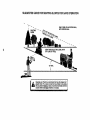
TO OPERATE ON HILLS
,_CAUTION:
Do not drive up or down
hills with slopes greater than 15 ° and do
not drive across any slope. Use the slope
guide provided at the back of this manual.
• Choose the slowest speed before starting up or down hills.
• Avoid stopping or changing speed on
hills.
• If slowing is necessary, move throttle
control lever to slower position.
• If stoppingis absolutely, necessary, push
clutch/brake pedal qu,ckly to brake position and engage parking brake.
• Move motion control lever to neutral (N)
position.
IMPORTANT: The motion control lever
does not return to neutral (N) position
when the clutclVbrake pedal is depressed.
• To restart movement, slowly release
parking brake and clutch/brake pedal.
• Slowly move motion control lever to
slowest setting.
• Make all tums slowly.
tively high; the second to desired height.
TO ADJUST GAUGE WHEELS
Gauge wheels are properly adjusted
when they are slightly off the ground when
mower is at the desired cutting height in
operating position. Gauge wheels then
keep the deck in proper position to help
prevent scalping in most terrain conditions.
• Be sure tractor is on a flat level surface.
• Lower mower and adjust mower to
desired cutting height.
• Remove retainer spring and clevis pin
which secure each gauge wheel bar.
t Lower gauge wheels to ground. Raise
gauge wheels slightly to align holes in
bracket and gauge wheel bar and insert
clevis pin. Gauge wheels should be
slightly off the ground.
• Replace retainer spring into clevis pin.
Retainer
Attachment Clutch
Switch Pull Out To
Attachment
Lift Lever
High Position
/
"Engage"
spring
Low
S_/Position
j?'
..S Discharge
_._'\ Guard
ush,n o
r_
, - :"
Disengage"
Clevis
Pin
IMPORTANT:
Be sure to readjust gauge
wheels if you change the cutting height of
the mower deck.
TO OPERATE
F-_j )_,,
TO TRANSPORT
When pushing or towing your tractor, be
sure to disengage transmission by placing
freewheel control in freewheeling
position. Freewheel control is located at the
rear drawbar of tractor.
• Raise attachment lift to highest position
with attachment lift control.
• Remove retainer spring from freewheel
control rod.
• Push control rod in to disengage transmission and reinsert retainer spring into
control rod hole now on back side of the
bracket.
• Do not push or tow tractor at more than
two (2) MPH.
• To reengage transmission, reverse
above procedure
MOWER
Your tractor is equipped with an operator
presence sensing switch. Any attempt by
the operator to leave the seat with the
engine running and the attachment clutch
engaged will shut off the engine.
• Select desired height of cut.
• Lower mower with attachment lift control.
• Start mower blades by engaging attachment clutch control.
• TO STOP MOWER BLADES - disengage attachment clutch control.
15
NOTE: Toprotecthoodfromdamage
whentransportingyourtractoron a truck
or a trailer,be surehoodis closedand
securedto tractor. Usean appropriate
meansof tyinghoodto tractor(rope,cord,
etc.).
TOWING CARTS AND OTHER
ATTACHMENTS
Towonlythe attachmentsthatare recommendedby andcomplywith specifications
of the manufacturerofyourtractor.Use
commonsensewhentowing.Tooheavyof
a load,whileon a slope,is dangerous.
Tirescanlosetractionwiththe groundand
causeyouto losecontrolof yourtractor.
BEFORE STARTING THE ENGINE
CHECKENGINEOIL LEVEL
• The enginein your tractor hasbeen
shipped,fromthe factory,alreadyfilled
with summerweightoil.
• Check engine oil with tractor on level
ground.
• Unthread and remove oil fill cap/dipstick; wipe oil off. Reinsert the dipstick
into the tube and rest oil fill cap on the
• tube. Do not thread the cap onto the
tube. Remove and read oil level. If necessary, add oil until =FULL" mark on
dipstick is reached. Do not overfill.
• For cold weather operation you should
change oil for easier starting (See "OIL
VISCOSITY CHART" in the Customer
Responsibilities section of this manual).
•* To change engine oil; see the Customer
Responsibilities section in this manual.
ADD
IMPORTANT: When operating in temperatures below 32°F(0°C), use fresh, clean
winter grade gasoline to help insure good
,_/Aweather starting.
RNING: Experience indicates that
alcohol blended fuels (calle_lgasohol or
using ethanol or methanol) can attract
moisture which leads to separation and
formation of acids during storage. Acidic
gas can damage the fuel system of an
engine while in storage. To avoid engine
problems, the fuel system should be emptied before storage of 30 days or longer.
Drain the gas tank, start the engine and let
it run untilthe fuel lines and carburetor are
empty. Use fresh fuel next season. See
Storage Instructionsfor additional
information. Never use engine or
carburetor cleaner products in the fuel
t_k or permanent damage may occur.
CAUTION: Fill to bottom of gas tank
filler neck. Do not overfill. Wipe off any
spilled oil or fuel. Do not store, spill or use
gasoline near an open flame.
TO START ENGINE
When starting the engine for the first time
or if the engine has run out of fuel, it will
take extra cranking time to move fuel from
the tank to the engine.
• Be sure freewheel control is in the
transmission engaged position.
• Sit on seat in operating position,
depress clutch/brake pedal and set
parking brake.
• Place motion control lever in neutral (N)
position.
• Move attachment clutch to =DISENGAGED" position.
• Move throttle control to fast position
• Pull choke control out for a cold engine
start attempt. For a warm engine start
attempt the choke control may not be
needed.
NOTE: Before starting, read the warm and
cold starting procedures below.
• Insert key into ignition and tum key
clockwise to =START" position and
release key as soon as engine starts.
Do not run starter continuously for more
than fifteen seconds per minute. If the
engine does not start after several
attempts, push choke control in, wait a
few minutes and try again. If engine still
does not start, pull the choke control out
and retry.
GASOLINE
• Fill fuel tank.qJse fresh, clean, regular
unleaded gasoline with a minimum of 87
octane. (Use of leaded gasoline will
increase carbon and lead oxide
deposits and reduce valve life). Do not
mix oil with gasoline. Purchase fuel in
quantities that can be used within 30
days to assure fuel freshness.
16
WARM WEATHER STARTING (50 ° F
AND ABOVE)
• When engine starts, slowly push choke
control in untilthe engine begins to run
smoothly. If the engine starts to run
roughly, pull the choke control out slightly for a few seconds and then continue
to push the control in slowly.
• The attachments and ground drive can
now be used. If the engine does not
accept the load, restart the engine and
allow it to warm up for one minute using
the choke as described above.
COLD WEATHER
BELOW)
STARTING
(50 ° F AND
• When engine starts, slowly push choke
control in until the engine begins to run
smoothly. Continue to push the choke
control in small steps allowing the
engine to accept small changes in
speed and load, until the choke control
is fully in. If the engine starts to run
roughly, pull the choke control out slightly for a few seconds and then continue
to push the control in slowly. This may
require an engine warm-up period from
several seconds to several minutes,
depending on the temperature.
AUTOMATIC
TRANSMISSION
WARM-UP
• Before driving the unit in cold weather,
the transmission should be warmed up
as follows:
• Be sure the tractor is on level ground.
• Place the motion control lever in neutral. Release the parking brake and
let the clutch/brake slowly return to
operating position.
• Allow one minute for transmission to
warm up. This can be done during the
engine warm up period.
• The attachments
can be used during
the engine warm-up period after the
transmission has been warmed up and
may require the choke control be pulled
out slightly.
NOTE: A high altitude (above 3000 feet)
or in cold temperatures (below 32 F) the
carburetor fuel mixture may need to be
adjusted for best engine performance.
See =TO ADJUST CARBURETOR"
in the
Service and Adjustments section of this
manual.
PURGE TRANSMISSION
_,CAUTION:
Never engage or disengage freewheel lever whUe the engine is
running.
To ensure proper operation and performance, it is recommended that the transmission be purged before operating tractor
for the first time. This procedure will
remove any trapped air inside the transmission which may have developed during
shippingof your tractor.
IMPORTANT:
Should your transmission
require removeal for service or replacement, it should be purged after reinstallation before operating the tractor.
• Place tractor safely on level surface with
engine off and parking brake set.
• Disengage transmission by placing freewheel control in freewheehng position
(See =TO TRANSPORT" in this section
of manual).
• Sitting in the tractor seat, start engine.
After the engine is running, move throttle control to slow position. With motion
control lever in neutral (N) position,
slowly disengage clutch/brake pedal.
• Move motion control lever to full forward
position and hold for five (5) seconds.
Move lever to full reverse position and
hold for five (5) seconds. Repeat'this
procedure throe (3) times.
NOTE: During this procedure there will be
no movement of drive wheels. The air is
being removed from hydraulic drive system.
• Move motion control lever to neutral (N)
position. Shut off engine and set parking
brake.
• Engage transmission by placing freewheel control in driving position (See
"TO TRANSPORT" in this section cf
manual).
• Sitting in the tractor seat, start engine.
After the engine is running, move throttle control to half (1/2) speed. With
motion control lever in neutral (N) position, slowly disengage clutch/brake
pedal.
• Slowly move motion control lever forward; after the tractor moves approximately five (5) feet, slowly move motion
control lever to reverse position. After
the tractor moves approximately five (5)
feet return the motion control lever to
the neutral (N) position. Repeat this procedure with the motion control lever
three (3) times.
• Your tractor is now purged and now
ready for normal operation.
17
MOWING TIPS
• If grass is extremely tall, it should be
mowed twice to reduce load and possible fire hazard from dried clippings.
Make first cut relatively high; the second
to the desired height.
• Do not mow grass when it is wet. Wet
grass will plug mower and leave undesirable clumps. Allow grass to dry
before mowing.
• Always operate engine at full throttle
when mowing to assure better mowing
performance and proper discharge of
material. Regulate ground speed by selecting a low enough gear to give the
mower the best cutting performance as
well as the quality of cut desired.
• When operating attachments, select a
ground speed that will suit the terrain
and give best performance of the attachment being used.
• Tire chains cannot be used when the
mower housing is attached to tractor.
• Mower should be properly leveled for
best mowing performance. See =TO
LEVEL MOWER HOUSING" in the
Service and Adjustments section of this
manual.
• Use the runner on the right hand side of
mower as a guide. The blade cuts
approximately an inch outside the runner.
• The left hand side of mower should be
used for trimming.
• Drive so that clippings are discharged
onto the area that has been cut. Have
the cut area to the right of the tractor.
This will result in a more even distribution of clippings and more uniform cutting.
• When mowing large areas, start by turning to the right so that clippings will discharge away from shrubs, fences, driveways, etc. After one or two rounds, mow
in the opposite direction making left
hand tums until finished.
18
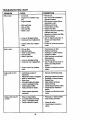
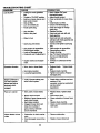
CUSTOMER
RESPONSIBILITIES
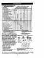
FILLMAINTENANCE
IN DATES
SCHEDULE
____o_f
"
AS
You
O,,T,,
--,"
o,.c,o,..o..
Check "13rePressure
Check Operator Presence and
T InterlockSy,=ems
R CheckforLooseFastenem
T
Lu_:at_
II/'
li_
c_
I# #
Chart
CA
0 CheckBmteryLevel
_Replace
Mower Blades
R
lit7
II_
i_
Battery
andTermklals/Recharge
CheckTmr_axleCooling
V#
IV#
Adjust Blade Belt(s) Tension
_s
Adjust Motion Drive Belt(s) Tension
Ks
CheckEngineOilLevel
E
N
Change Engine Oil
I_t2,s
Clean Air Rlter
i If=
Clean Air Screen
iV#2
Inspect Muffler/Spark Arrester
t# /
V#
Replace Oil F'_er (If equipped)
EN Clean Engine Coo4ing
Replace Spark Plug
._=
_
Replace Nr Fkter Paper Cartddge
I_
_2
Replace Fuel Filter
I_ #
1 - Chang* mo_ one3 ,,v_m op_alJng undera hNNy I_d or In highambl*nt hm_'ur_,
2. Serv_e rr_ ohm whono_
In dldy or dustycondi_ons.
3 - If_0ped
wlmoi flier, change dl qNeP/50 hour_.
4. Replace
bladesmo_ _*n v,t,mmo_dng
_ _ndy _i,
s - He_
_h _
s.pmm.
7 -T_htenfrontmd_phil boltto3SIL-Ibs.rm0dmum.
Donoqo_on.
GENERAL RECOMMENDATIONS
LUBRICATION
CHART
The warranty on this tractor does not cover
@Tie Rod Ball Joints
items that have Deen suDjected to operator
@Spindle Zerk
abuse or negligence, io receive TUllvalue
Trom the warranty operator must maintain
tractor as nstructeo in this manual. Some
eFront
OFront
adjustments will need to be made pedodiWheel
_'_."
I
Wheel
cally to properly maintain your tractor.
_Spindle
Zerk
Bearing _
Bearing
All adjustments in the _ervice an(]
Zerk
Adjus'cments section of this manual should
_Zerk
be checked at least once each season.
•Steering
• Once a year you should replace the
Sector
spark plugz clean or replace air filter and Gear Teeth
cneck b a(]es and bens ;'or wear. P_new
spark plug and clean air filter assure
proper air-fuel mixture and help your
engine run eetter and last longer.
BEFORE EACHUSE
: Check engine oil level.
Check brake operation.
Check operator
presence ano intenocK
•Check
, .
systemstireforpressure.
proper operation. .
Check for loose fasteners.
eGeneral
Purpose
Grease
.
OSpray
Silicone
lubriant
(Move _s . to
Lubricate)
ORefer to
Customer
Responsibilities
ENGINE
Section
IMPORTANT: Do not oil or grease the pivot points which have special nylon bearings. Viscous lubricants will attract dust and dirt that will shorten the life of the self-lubricating bearings. If you feel
thev must be lubricated, use onlv a dry. powdered graphite type lubricant sparingly,
19
TRACTOR
Always observe safety rules when performing any maintenance.
BRAKE OPERATION
If tractor requires more than six (6) feet
stopping distance at high speed in highest
gear, then brake must be adjusted. (See
"TO ADJUST BRAKE" in the Service and
Adjustments section of this manual).
TIRES
• Maintain proper air pressure in all tires
(See =PRODUCT SPECIFICATIONS"
on page 3 of this manual).
• Keep tires free of gasoline, oil, or insect
control chemicals which can harm rubber.
• Avoid stumps, stones, deep ruts, sharp
objects and other hazards that may
cause tire damage.
NOTE: To seal tire punctures and prevent
flat tires due to slow leaks, tire sealant
may be purchased from your local parts
dealer. Tire sealant also prevents tire dry
rot and corrosion.
OPERATOR
PRESENCE
SYSTEM
Be sure that operator presence and interlock systems are working properly. If your
tractor does not function as described
below, repair the problem immediately.
• The engine should not start unless the
clutch/brake pedal is fully depressed
and attachment clutch control is in the
disengaged position.
• When the engine is running, any
attempt by the operator to leave the
seat without first setting the parking
brake should shut off the engine.
• When the engine is running and the
attachment clutch is engaged, any
attempt by the operator to leave the
seat should shut off the engine.
• The attachment clutch should never
operate unless the operator is in the
seat.
BLADE CARE
For best results mower blades must be
kept sharp. Replace bent or damaged
blades.
BLADE REMOVAL
• Raise mower to highest position to allow
access to blades.
• Remove hef'bolt, lock washer and flat
washer securing blade.
• Install new or resharpened blade with
trailing edge up towards deck as shown.
IMPORTANT: To ensure proper assembly,
center hole in blade must align with star
on mandrel assembly.
• Reassemble hex bolt, lock washer and
flat washer in_exact order as shown.
• Tighten bolt ,securely (27-35 Ft. Lbs.
20
torque).
IMPORTANT:
treated.
Blade bolt is Grade 8 heat
Mandrel
Blade
Center
Hole
_
Hex Bolt
(Grade 8)_k=
Star
*A Grade 8 heat treated bolt can be
identifiedby six lineson the bolt head.
TO SHARPEN BLADE
NOTE: We do not recommend sharpening
blade, but if you do, be sure the blade is
balanced.
Care should be taken to keep the blade
balanced. An unbalanced blade will cause
excessive vibration and eventual damage
to mower and engine.
• The bladecanbe
sharpened with afile
or on a grinding wheel. Do not attempt
to sharpen while it is on the mower.
• To check blade balance, you will need a
5/8" diameter steel bolt, pin, or a cone
balancer. (When using a cone balancer,
follow the instructions supplied with balancer).
• Slide blade onto an unthreaded portion
of the steel bolt or pin and hold the bolt
or pin parallel with the ground. If blade
is balanced, it should remain in a hodzontal position. If either end of the blade
moves downward, sharpen the heavy
end until the blade is balanced.
NOTE; Do not use a nail for balancing
blade. The lobes of the center hole may
appear to be centered, but are not.
ade
or Pin
BATrERY
--"_
-_
Your tractor has a battery charging system
which is sufficient for normal use.
However, periodic charging of the battery
with an automotive charger will extend its
life.
• Keep battery and terminals clean.
i
Keep
holes
eep small
batteryvent
bolts
tight.open.
Recharge at 6-10 amperes for I hour.
TO CLEAN BA'I-rERY AND TERMINALS
Corrosion and dirt on the battery and terminals can cause the battery to "leak"
power.
Remove terminal guard.
Disconnect BLACK battery cable first
then RED battery cable and remove
battery fr_om tractor.
TO CHANGE
• Rinse the battery with plain water and
dry.
• Clean terminals and battery cable ends
with wire brush until bright.
• Coat terminals with grease or petroleum
ENGINE
OIL
Determine temperature range expected
before oil change. All oil must meet API
service classification SF, SG, or SH.
• Be sure tractor is on level surface.
iel !.
• Oil will drain more freely when warm.
• Catch oil in a suitable container.
• Reinstall battery (See "REPLACING
BATTERY" in the SERVICE AND
ADJUSTMENTS
section of this manual).
• Remove oil fill cap/dipstick. Be careful
not to allow dirt to enter the engine
when changing oil.
• Remove drain plug.
• After oil has drained completely, replace
oil drain plug and tighten securely.
• Refill engine with oil through oil fill dipstick tube. Pour slowly. Do not overfill.
For approximate capacity see =PRODUCT SPECIFICATIONS"
on page 5 of
this manual.
V-BELTS
Check V-belts for deterioration and wear
after 100 hours of operation and replace if
necessary. The belts are not adjustable.
Replace belts if they begin to slip from
wear.
TRANSAXLE
COOLING
The transmission fan and cooling fins
should be kept clean to assure proper
cooling.
Do not attempt to clean fan or transmission while engine is running or while the
transmission is hot.
• Inspect cooling fan to be sure fan
blades are intact and clean.
• Inspect cooling fins for dirt, grass clipdPingsand other materials. To prevent
amage to seals, do not use compressed air or high pressure sprayer to
clean cooling fins.
TRANSAXLE
PUMP FLUID
• Use gauge on oil fill cap/dipstick for
checking level. Insert dipstick into the
tube and rest the oil fill cap on the tube.
Do not thread the cap onto the tube
when taking reading.
Keep oil at
=FULL" line on dipstick. Tighten cap
onto the tube securely when finished.
Oil Drain Plug
The transaxle was sealed at the (sctory
and fluid maintenance is not required for
the life of the transaxle. Should the
transaxle ever leak or require servicing,
contact your nearest authodzed service
center/department.
ENGINE
LUBRICATION
Air Screen
Only use high quality detergent oil rated
with API service classification SF, SG, or
SH. Select the oil's SAE viscosity grade
according to your expected operating temperature.
Oil Fill
Cap/Dipstick
CLEAN AIR SCREEN
Air screen must be kept free of dirt and
chaff to prevent engine damage from overheating. Clean with a wire brush or compressed air to remove dirt and stubborn
dried gum fibers.
Change the oil after every 50 hours of
operation or at least once a year if the
tractor is not used for 50 hours in one
year.
Check the crankcase oil level before starting the engine and after each eight (8)
hours of operation. Tighten oil fill cap/dipstick securely each time you check the oil
level.
21
CLEAN AIR INTAKE/COOLING AREAS
To insure proper cooling, make sure the
grass screen, cooling fins, and other
external surfaces of the engine are kept
clean at all times.
Every 100 hours of operation (more often
under extremely dusty, dirty conditions),
remove the blower housing and other
cooling shrouds. Clean the cooling fins
and external surfaces as necessary. Make
sure the cooling shrouds are reinstalled.
NOTE: Operating the engine with a
blocked grass screen, dirty or plugged
cooling fins, and/or cooling shrouds removedwill cause engine damage due to
overheating.
AIR FILTER
• Reassemble air cleaner, cartridge plate,
and nut.
• Reinstall air cleaner cover and secure
by tightening knob.
ENGINE OIL FILTER
Replace the engine oil filter every season
or with every second oil change if the tractor is used more than 100 hours in one
year.
MUFFLER
Inspect and replace corroded muffler and
spark arrester (if equipped) as it could create a fire hazard and/or damage.
SPARK PLUGS
Replace spark plugs at the beginning of
each mowing season or after every 100
hours of operation, whichever occurs first.
Spark plug type and gap setting are
shown in =PRODUCT SPECIFICATIONS"
on page 5 of this manual.
IN-LINE FUEL FILTER
Your engine will not run properly using a
dirty airfllter. Clean the foam pre-cleaner
after every 25 hours of operation or every
season. Service paper cartridge every
100 hours of operation or every season,
whichever occurs first.
Service air cleaner more often under dusty
conditions.
• Loosen knob and remove cover.
TO SERVICE PRE-CLEANER
• Slide foam pre-cleaner off cartridge.
• Wash it in liquid detergent and water.
• Squeeze it dry in a clean cloth. Allow it
to dry.
• Saturate it in engine oil. Wrap it in
clean, absorbent cloth and squeeze to
remove excess oil.
TO SERVICE CARTRIDGE
• Replace a dirty, bent, or damaged cartridge.
The fuel filter should be replaced once
each season. If fuel filter becomes
clogged, obstructing fuel flow to carburetor, replacement is required.
• With engine cool, remove filter and plug
fuel line sections.
• Place new fuel filter in position in fuel
line with arrow pointing towards carburetor.
• Be sure there are no fuel line leaks and
clamps are pmperiy positioned.
Cartridge
Foam
Pre-cleaner
Cartridge
Plate
CLEANING
Rubber
Seal
of all foreign
i Clean
engine,matter.
battery, seat, finish, etc.
Keep finished surfaces and wheels free
of all gasoline, oil, etc.
• Protect painted surfaces with automotive type wax.
We do not recommend using a garden
hose to clean your tractor unless the electrical system, muffler, air filter and carburetor are covered to keep water out. Water
in engine can result in a shortened engine
life.
Nut
NOTE: Do not wash the paper cartridge
or use pressurized air, as this will damage the cartridge.
• Remove nut and cartridge plate.
• Reinstall the pre-cleaner (cleaned and
oiled) over the paper cartridge.
• Check rubber seal for damage and
proper position around stud. Replace if
n6ces_ary.
22
,_CAUTION:
Before performing any service or adjustments:
• Depress clutch/brake pedal fully and set parking brake.
• Place motion control lever in neutral (N) position.
• Place attachment clutch in =DISENGAGED"
position.
i
Make
sure thekey
blades
movingkey.
parts have completely stopped.
um ignition
"OFF"and
andallremove
Disconnect spark plug wire from spark plug and place wire where it cannot come
in contact with plug.
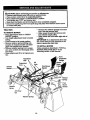
TRACTOR
TO REMOVE MOWER
• Place attachment clutch in =DISENGAGED" position.
•Tum
height adjustment knob to lowest
setting.
• Lower mower to its lowest position.
Remove retainer spring holding antiswaybar to chassis bracket and disengage anti-swaybar from bracket.
• Remove retainer springs from suspension arms at deck and disengage arms
from deck.
• Raise attachment lift to its highest position.
• Remove two retainer spdngs from each
front link and remove links.
• Slide mower forward and remove belt
from electric clutch pulley.
• Slide mower out from under right side of
tractor.
IMPORTANT: If an attachment other than
the mower deck is to be mounted on the
tractor, remove the front links.
TO INSTALL
MOWER
Follow procedure descdbed in =INSTALL
MOWER AND DRIVE BELT" in the
Assembly section of this manual.
, Front
Suspension
Bracket
Adjustment
Nuts
Suspension
Arms
Lift
Unks
Front Mower
Chassis
Bracket
Retainer
Springs
Mower
Bracket
_etainer
Spring
Anti-Sway
Bar
Retainer Springs
23
TO LEVELMOWERHOUSING
Adjustthe mowerwhiletractoris parked
on levelgroundor driveway.Makesure
tires areproperlyinflated(See "PROD-
• When distance "F" is 118" to 1/2" lower
at front than rear, tighten nut "H"
against trunnion on both front links.
NOTE: Each full turn of nut "G" will
UCT SPECIFICATIONS").
If tires are
over or underinflated, you will not properly
adjust your mower.
SIDE-TO-SIDE
ADJUSTMENT
change dim. "F" by approximately
Mandrel
• Raise mower to its highest position.
• Measure height from bottom of deck
curt to ground level at front corners of
mower. Distance "A" on both sides of
mower should be the same.
• If adjustment is necessary, make adjustment on one side of mower only.
• To raise one side of mower, tighten lift
link adjustment nut on that side.
• To lower one side of mower, loosen lift
link adjustment nut on that side.
NOTE:
Each full turn of adjustment nut
will change mower height about 3/16".
• Recheck measurements
after adjusting.
Bottom
o,
__
___
3/8".
• Recheck side-to-side adjustment.
*#
J
_
r .....
L_=-"
Both Front
_ .=Links
_ _ih°uld
-_--_-_.
be__
Equal.in Length
Bottom
P
Nut "H"_
==
"_ Nut G"
FRONT-TO-BACK
ADJUSTMENT
IMPORTANT:
Deck must be level side-toside. If the followingfrent-to-back
adjustment is necessary, be sure to adjust both
front links equally so mower will stay level
side-to-side.
?
Links_
TO REPLACE
MOWER
MOWER
DRIVE
DRIVE BELT
BELT REMOVAL
• Park tractor on a level surface. Engage
parking brake.
• Remove screws from left hand mandrel
cover and remove cover.
• Roll belt over the top of left hand mandrel pulley.
• Remove belt from electric clutch pulley.
To obtain the best cutting results, the
mower housing should be adjusted so the
front is approximately 1/8" to 1/2" lower
than the rear when the mower is in its
highest position.
Check adjustment on right side of tractor.
Measure distance "F* directly in front of
and behind the mandrel at bottom edge of
mower housing as shown.
• Before making any necessary adjustments, check that both front links are
equal in length.
• If links are not equal in length, adjust
one link to same length as other link.
• To lower front of mower housing, loosen
nut "G" on both front links an equal
number of tu_s.
• When distance "F" is 1/8" to 1/2" lower
at front than rear, tighten nut "H" against
trunnion on both front links.
• To raise front of mower housing, loosen
nut "H" from tnjnnion on both front links.
Tighten nut "G" on both front links an
equal number of turns.
Remove belt from idler pulleys.
Remove any dirt or grass clippings
which may have accumulated around
mandrels and entire upper deck surface.
• Check primary idler arm and two idlers
to see that they rotate freely.
• Be sure spring is securely hooked to primary idler arm and bolt in mower housing.
24
Check pdmary idler arm and two idlers
i to see that they rotate freely.
Be sure spring is securely hooked to primary idler arm and bolt in mower housing.
MOWER DRIVE BELT INSTALLATION
• Install belt in both idlers. Make sure belt
is in both bolt keepers at the idlers as
shown.
Left Hand
Mandrel
Cover
• Install new belt onto electric clutch pulley.
• Roll belt into upper groove of left hand
mandrel pulley.
• Carefully check belt routing making sure
belt is ,n the grooves correctly and
inside belt keepers.
• Reassemble left hand mandrel cover.
Idler
Pulleys
Electric
Clutch
Left Hand
Mower
Drive
Belt
Belt
Keepem
Primary
Idler Arm
TO REPLACE
BELT
MOWER
BLADE
Park the tractor on level surface.
DRIVE
• Check secondary idler arm and idler to
see that they rotate freely.
Engage
idler
armspring
and sway-bar
bracket.
Be sure
is hookedin
secondary
Install new belt in lower groove of left
hand mandrel pulley, idler pulley, and
center mandrel pulley as shown.
Roll belt over right hand mandrel pulley.
belt
in all
i Make sure
Js
grooves properly.
Reconnect spring to bolt in mower
housing and reinstall right hand mandre
cover.
• Reinstall mower to tractor (See
=INSTALL MOWER AND DRIVE BELT"
in the Assembly section of this manual).
• Reassemble mower drive belt (See =TO
REPLACE MOWER DRIVE BELT" in
this section of this manual).
parking brake.
Remove mower drive bolt (See "TO
REPLACE MOWER DRIVE BELT" in
this section of this manual).
• Remove mower (See =TO REMOVE
MOWER" in th,s section of this manual).
• Remove screws from fight hand mandrel cover and remove cover. Unhook
spring from bolt on mower housing.
• Carefully roll belt off fight hand mandrel
pulley.
• Remove belt from center mandrel pulley, idler pulley, and left hand mandrel
pulley.
• Remove any dirt or grass which may
have accumulated around mandrels and
entire upper deck surface.
25
Left Hand
Mandrel
Right Hand
Mandrel
Cover
Secondary Idler Arm
Spring
Anti-Sway-Bar
Bracket
TO ADJUST
ATTACHMENT
Screw
CLUTCH
The electric clutch should provide years of
service. The clutch has a built-in brake
that stops the pulley within 5 seconds.
Eventually, the internal brake will wear
which may cause the mower blades to not
engage, or, to not stop as required.
Adjustments should be made by your
nearest authonzed service center/dooartment.
• Make sure attachment clutch and ignition switches are in =OFF" position.
• Adjust the three nylon Iocknuts until
space between clutch plate and rotor
measures .012' at all three slot locations cut in the side of brake plate.
NOTE: After installing a new electric
clutch, run tractor at full throttle and
engage and disengage electric clutch 10
cycles to wear in clutch plate.
Slot (3)
Clutch Plate
Rotor
-,_..
t
\
(3)
_
TO ADJUST
BRAKE
/ i J .or2.
_.
Plate
W'dhParking
. Brake
_.
/_-1-1/2"-'_
\
TO REPLACE
\'
MOTION
Nut "A"
/\
_
Operating
DRIVE BELT
Park the tractor on level surface. Engage
parking brake. For ease of service there
a belt installation guide decal on bottom
of left footrest.
• Remove mower (See "TO REMOVE
MOWER" in this section of this manual.)
BELT REMOVAL • Engage parking brake (creates slack in
belt).
• Remove belt from clutching and fan
idler pulleys.
• Loosen belt keeper above transaxle pulley.
• Remove belt from transaxle pulley.
• Remove belt from engine pulley and
front V-idler pulley.
• Pull belt out of all belt keepers and
remove from tractor.
BELT INSTALLATION • Place V part of belt intogrooves on
engine pulley and front V-idler, making
sure to route belt inside of all belt keep
Your tractor is equipped with an adjustable
brake system which is mounted on the
side of the transaxle.
If tractor requires more than six (6) feet
stooping distance at high speed in highest gear, then brake must be adjusted.
• Depress clutch/brake pedal and engage
parking brake.
ers.
• Measure distance between brake operating arm and nut =A" on brake rod,
• Route belt on right side, coming from V• If distance is other than 1-1/2", loosen
idler, towards back of tractor, above
jam nut and tum nut =A" until distance
midspan belt keeper and to top of
becomes 1-112". Retighten jam nut
trensaxle pulley.
against nut =A".
• Route belt on left side, coming from
• Road test tractor for proper stooping
engine pulley, towards back of tractor
distance as stated above. Readjust if
and through loop in midspan bolt keeper.
necessary. If stopping distance is still
greater than six (6)feet in highest gear,
• Place V part of belt into grooves on
further maintenance is necessary.
transaxle and fan idler pulleys, making
Contact your nearest authorized sersure to route belt inside of all belt keepers.
-vice-center/department,
26
• Retighten belt keeper above transaxle
pulley,
• Place belt around clutching idiom as
shown, making sure to route belt inside
of all belt keepers.
• Chock to be sure belt is positioned correctly and is on proper side of all belt
keepers.
• Reinstall mower.
IMPORTANT: Chock brake adjustment.
Tractor V-Belt Drive Schematic
Viewed from L.H. Side of Tractor
Belt
Transaxle
Belt Keepers
I
(_j._r-
En._ine
Belt
Fan
Keeper
Idler
l
TO ADJUST
MOTION
CONTROL
TRANSMISSION REMOVAUREPLACEMENT
Should your transmission require removal
for service or replacement, it should be
purged after reinstallationand before
operating the tractor. See "PURGE
TRANSMISSION" in the Operation section
of this manual.
TO ADJUST STEERING WHEEL ALIGNMENT
If steeringwheel crossbars are not horizontal (left to right) when wheels are positioned straight forward, remove steenng
wheel and reassemble per instructionsin
the Assembly section of this manual.
FRONT WHEEL TOE-IN ADJUSTMENT
Front wheel toe-in is required for proper
steering operation. Tee-in was set at the
factory and adjustment should not be necessary. If parts in the front axle or steering
mechanism have bean replaced or damaged, check toe-in and adjust if necessary.
TO CHECK TOE-IN
Position
wheels
straight
ahead.at
Measure front
distance
between
wheels
front and rear of tires (dimensions =A"
and "B._.).
• Front dimension •A" should be 1/8" to
1/4" less than rear dimension "S".
LEVER
The motion control lever has been preset
at the factory and adjustment should not
be nocessary.
If for any reason the motion control lever
will not hold its position while at a selected
speed, it may be adjusted at the friction
TO ADJUST TOE-IN
• Loosen jam nuts at adjustment sleeves
on tie rod.
• Adjust tie red until dimension =A" is 1/8"
to 1/4" less than dimension "B'.
• Tighten jam nuts securely.
FRONT WHEEL CAMBER
pack Iocatedon the right side of chassis.
Park tractor on level surface. Stop tractor by turning ignition key to "OFF" position and engage parking brake.
• Place motion control lever in neutral (N)
position.
The front wheel camber is not adjustable
on your tractor, If damage has occurred to
affect the front wheel camber, contact your
nearest authorized service center/department.
Tighten
IocknutIocknut,
114 turn.
hile holding
loosen jam nut
While holding iocknut, tighten jam nut
securely.
NOTE:- If for any reason the effort to
move the motion control lever becomes
too excessive, reverse the above adjustment procedure by loosening Iocknut 1/4
turn.
Road test tractor after adjustment and
repeat procedure if necessary.
i
ustment
Sleeves
_e Rod
Jam Nu_
27
TO REMOVEWHEELFORREPAIRS
FRONT WHEEL
• Block up axle securely.
• Remove axle cover, retaining dng and
washers to allow wheel removal.
• Repair tire and reassemble.
• Replace washers and snap retaining
dng securely in axle groove.
• Replace axle cover.
REAR WHEEL.* Block rear axle securely.
Remove five (5) hub bolts to allow
wheel removal.
• Repair tire and reassemble. Replace
and tighten hub bolts securely.
NOTE: To seal tire punctures and prevent
flat tires due to slow leaks, tire sealant
may be purchased from your local parts
dealer. Tire sealant also prevents tire dry
rot and corrosion.
Washers
Retaining _
fff_'l_
_
TO START
TERY
CABLES,
REVERSE
• BLACK cable first from chassis and
then from the fully charged battery.
• RED cable last from both batteries.
"Positive*_=__L==Negative"
REPLACING
BATTERY
ACAUTION:
Do not short battery terminals by allowing a wrench or any other
object to contact both terminals at the
same time. Before connecting battery,
remove metal bracelets, wdstwatch
bands,rings,etc.
Positive terminal must be connected first
to prevent sparking from accidental
grounding.
• Lift hood to raised position.
Ax,e
Cover
TO REMOVE
ORDER -
ENGINE
WITH A WEAK
BAT-
ACAUTION:
Lead-acid batteries generate explosive gases. Keep sparks, flame
and smoking materials away from batteries. Always wear eye protection when
around batteries.
If your battery is too weak to start the
engine, it should be recharged. (See
"BA'I-FERY" in the MAINTENANCE
section of this manual).
If "jumper cables" are used for emergency
starting, follow this procedure:
IMPORTANT:
Your tractor Is equiped with
a 12 volt negative grounded system. The
other vehical must also be a 12 volt negat!ve grounded system. Do not use your
tractor battery to start other vehicles.
TO ATTACH JUMPER
CABLES
• Remove terminal guard.
Disconnect BLACK battery cable then
RED battery cable and carefully remove
battery from tractor.
• Install new battery with terminals in
same position as old battery.
Reinstall terminal guard.
First connect RED battery cable to positive (+) battery terminal with hex bolt
and keps nut as shown. Tighten securein
• _onnect BLACK grounding cable to
negative (-)battery terminal with
remaining hex bolt and keps nut.
Tighten
securely.
• Close terminal access doors.
• Close hood.
Terminal
A_e_
;N=
HexBolt
-
• Connect each_end of the RED cable to
the POSITIVE (+) terminal of each battery, taking care not to short against
chassis.
• Connect one end of the BLACK cable to
the NEGATIVE _-) terminal of fully
charged battery.
• Connect the other end of the BLACK
cable to good CHASSIS GROUND,
away from fuel tank and battery.
.. Pesitive
(Red) Cable
Guard
(Black)
Cable
28
TO REPLACEHEADLIGHTBULB
• Raisehood.
Hood
• Pull bulb holder out of the hole in the
backside of the grill.
• Replace bulb inholder an_dpush bulb
holder securely back into the hole in the
backside of the grill.
• Close hood.
INTERLOCKS
AND RELAYS
Loose or damaged wiring maycause your
tractor to run poorly, stop running, or prevent it from starting.
• Check wiring. See electdcal widng diagram in the Repair Parts section.
TO REPLACE FUSE
Replace with 30 amp automotive-type
plug-in fuse. The fuse holder is located
behind the dash.
TO ADJUST ATTACHMENT
LIFT
SPRING
• While holding spdng bushing with
wrench, loosen jam nut.
• Turn adjustment bolt clockwise to
extend spdng and reduce lift effort for
heavier attachments.
• Turn adjustment bolt counterclockwise
for lighter attachments.
• Retighten jam nut against spdng bushin q..
IMPORTANT:
Do not adjust for maximum
spring tension when using light attachments such as a mower. Adjust lift lever
spdng to aid in lifting attachment. Do not
overpower spring. When removing attachment, always adjust spring tension to its
lowest position.
Jam Nut
Headlight
Wire
Connector
ENGINE
Maintenance, repair, or replacement of the
emission control devices and systems,
which are being done at the customers
expense, may be performed by any nonroad engine repair establishment or individual. Warranty repairs must be performed by an authodzed engine manufacturer's service outlet.
TO ADJUST THROTTLE CONTROL
CABLE
The throttle'control has been preset at the
factory and adjustment should not be necessary. Check adjustment as described
below before loosening cable. If adjustment is necessary, proceed as follows:
i
Spring
Bolt
control
lever not
to fast
position.
ith engine
running,
move throttle
Check that speed control lever is
against stop screw. If it is not, loosen
casing clamp screw and pull throttle
cable until lever is against screw.
Tighten clamp screw securely.
Idle
Speed
Adjusting
Screw
Needle
Q
%
•
•
Attachment
Uft Spring
TO REMOVE HOOD AND GRILL
Stop
Screw
Throttle
Control
Cable
ASSEMBLY
• Raise hoed.
• Unsnap headlight wire connector.
Stand in front of tractor. Grasp hood at
sides, tilt toward engine and lift off of
tractor.
Choke
Control
Cable
• To replace, reverse above procedure.
Clamp Screw
29
TO ADJUST CHOKE CONTROL
The choke control has been preset at the
factory and adjustment should not be necessary, check adjustment as described
below before loosening cable. If adjustment is necessary, proceed as follows:
• With engine not running, move choke
control (located on dash panel) to full
choke position.
• Remove air cleaner cover, filter and cartridge plate to expose carburetor choke
(See =AIR FILTER" in the Customer Responsibilities section of this manual).
• Choke should be closed. If it is not,
loosen casing clamp screw and move
choke cable untilchoke is completely
closed. Tighten casing clamp screw securely.
• Reassemble air cleaner.
• With engine off turn idle fuel adjusting
needle in (clockwise) closing it finger
tight and then turn out (counterclockwise) 1 tum.
FINAL SETTING
-
• Start engine and allow to warm for five
minutes. Make final adjustments with
engine running and shift/motion control
lever in neutral (N) position.
• The high idle is set at the factory and
cannot be adjusted.
• Idle sDeed setting - With throttle control
lever in slow position, engine should
idle at 1200 RPM. If engine idles too
slow or fast, turn idle speed adjusting
screw in or out until correct idle is
attained.
• Idle fuel needle settina - With throttle
control lever in slow position, turn idle
fuel adjusting needle in (clockwise) until
engine speed decreases and then tum
out (counterclockwise) approximately
3/4 turn to obtain the best low speed
performance.
• Recheck idle speed. Readjust if necessary.
Closed for
ACCELERATION
TEST -
• Move throttle control lever from slow to
TO ADJUST
fast position. If engine hesitates or dies,
tum idle fuel adjusting needle out
(counterclockwise) 1/8 tum. Repeat test
and continue to adjust, if necessary,
until engine accelerates smoothly.
High speed stop is factory adjusted. Do
not adjust-damage may result.
IMPORTANT:
Never tamper with the
engine govern0 r, which is factory set for
proper engine speed. Overspeeding the
engine above the facory high speed setting can be dangerous. If you think the
engine-governed high speed needs
adjusting, contact your nearest authorized
service senter/department,
which has
proper equipment and experience to make
any necessary adjustments.
CARBURETOR
The carburetor has been present at the
factory and adjustment should not be necessary. However, minor adjustment may
be required to compensate for differences
in fuel, temperature, altitude or load. Ifthe
carburetor does need adjustment, proceed
as follows:
In general, tuming the adjusting needles
in (clockwise) decreases the supply of fuel
to the engine giving a leaner fuel/a=r mixture. Turning the adjusting needles out
(countemlockwise) increases the supply of
fuel to the engine giving a richer fuel/air
mixture.
IMPORTANT: Damage to the needles
and the seats in carburetor may result if
screw is turned in too tight.
PRELIMINARY
SETTING
-
• Be sure you have a clean air filter, and
the throttle control cable is adjusted
propedy (see "TO ADJUST THRO'I-I'LE
CONTROL CABLE" in the Service and
Adjustments section of this manual).
30
Immediatelyprepareyourtractorfor storageat the endof the seasonor if the tractor will not be usedfor 30 days or more.
_,CAUTION:
Never store the tractor with
gasoline in the tank inside a building
where fumes may reach an open flame or
spark. Allow the engine to cool before storing in any enclosure.
TRACTOR
Remove mower from tractor for winter
storage. This will allow you to clean it thoroughly. Remove all dirt, grease, leaves,
etc. Store in a clean, dry area.
• Clean entire tractor (See =CLEANING"
in the Maintenance section of this manual).
• Inspect and replace belts, if necessary
(See belt replacement instructions in the
Service and Adjustments section of this
manual).
• Lubricate as shown in the Maintenance
section of this manual.
• Be sure that all nuts, belts and screws
are securely fastened. Inspect moving
parts for damage, breakage and wear.
Replace if necessary.
• Touch up all rusted or chipped paint surfaces; sand lightly before painting.
BATTERY
• Fully charge the battery for storage.
• After a period of time in storage, battery
may require recharging.
• To help prevent corrosion and power
leakage during long periods of storage,
battery cables should be disconnected
and battery cleaned thoroughly (see
"TO CLEAN BATTERY AND TERMINALS" in the Maintenance section of
Also, experience indicates that alcohol
blended fuels (called gasohol or using
ethanol or methanol) can attract moisture
which leads to separation and formation of
acids during storage. Acidic gas can damage the fuel system of an engine while in
storage.
• Drain the fuel tank.
• Start the engine and let it run until the
fuel lines and carburetor are empty.
• Never use engine or carburetor cleaner
products in the fuel tank or permanent
damage may occur.
• Use fresh fuel next season.
NOTE: Fuel stabilizer is an acceptable
altemative in minimizing the formation of
fuel gum deposits during storage. Add stabilizer to gasoline in fuel tank or storage
container. Always follow the mix ratio
found on stabilizer container. Run engine
at least 10 minutes after adding stabilizer
to allow the stabilizer to reach the carburetor. Do not drain the gas tank and carburetor if using fuel stabilizer.
ENGINE OIL
Drain oil (with engine warm) and replace
with clean engine oil. (See =ENGINE" in
the Maintenance section of this manual).
CYLINDERS
• Remove spark plug(s).
• Pour one ounce of oil through spark plug
hole(s) into cylinder(s).
• Turn ignition key to =START" position for
a few seconds to distribute oil.
• Replace with new spark plug(s).
OTHER
• Do not store gasoline from one season
to another.
this manual).
• After cleaning, leave cables disconnected and place cables where they cannot
come in contact with battery terminals.
• If battery is removed from tractor for
storage, do not store battery directly on
concrete or damp surfaces.
• Replace your gasoline can if it starts to
rust. Rust and/or dirt in your gasoline will
cause problems.
• If possible, store your tractor indoors
and cover it to give protection from dust
and dirt.
• Cover your tractor with a suitable protective cover that does not retain moisture.
ENGINE
FUEL SYSTEM
Do not use plastic. Plastic cannot
breathe, which allows condensation to
form and cause your tractor to rust.
IMPORTANT:
Never cover tractor while
engine and exhaust areas are still warm.
IMPORTANT: It is important to prevent
gum deposits from forming in essential
fuel system parts such as carburetor, fuel
filter, fuel hose, or tank during storage.
31
TROUBLESHOOTING CHART
F>ROBLEM
Willnotstart
CAUSE
CORRECTION
=• Out of fuel.
• Engine not =CHOKED" prop
edy,
• Engine flooded.
• RII fuel tank.
• See "TO START ENGINE" in
Operationsection.
• Walt several minutes before
•
•
•
•
•
•
•
•
• Engine valves out of adjustment,
attempting to start.
Replace spark plug•
Clean/replace air filter.
Replace fuel filter.
Drain fuel tank and carburetor,
refill tank with fresh
gasoline and replace fuel filter.
• Check all widng,
• See "To Adjust Carburetor" in
Service and Adjustments
section.
• Contact an authodzed service
center.
•
•
•
•
•
•
•
•
•
•
Bad spark plug.
Dirty air filter•
Dirty fuel filter.
Water in fuel.
• Loose or damaged widng.
• Carburetor out of adjustment.
Hard to start
Dirty air filter.
Bad spark plug.
Weak or dead battery,
Dirty fuel filter,
Stale or dirty fuel,
• Loose or damaged widng.
• Carburetor out of adjustment.
• Engine valves out of adjustment.
Engine will not turn
over
• Clutch/brake pedal not
depressed.
• Attachment dutch is engaged.
• Weak or dead battery,
• Blown fuse.
•
•
•
•
Corroded battery terminals.
Loose or damaged widng.
Faulty ignitionswitch,
Faulty solenoid or starter.
• Faulty operator presence
switch(es).
Clean/replace air filter.
Replace spark plug,
Recharge or replace battery.
Replace fuel filter.
Drain fuel tank and refill with
fresh gasoline.
• Check all widng.
• See "ToAdjust Carburetor"in
Service and Adjustments
section.
• Contact an authorized service
center.
• Depress dutch/brake pedal.
•
•
•
•
•
•
•
Disengage attachment clutch.
Recharge or replace battery.
Replace fuse.
Clean battery terminals.
Check all wiring.
Cheddraplace ignifion switch.
Check/replace solenoid or
starter.
• Contact an authodzed service
centen
I
Engine clicks but.will
not start
•
•
•
•
Weak or dead battery.
Corroded battery terminals.
Loose or damaged widng.
Faulty solenoid or starter.
32
• Recharge or replace battery.
• Clean battery terminals.
• Check all wiring.
• Check/replace solenoid or
starter.
"ROUBLESHOOTING CHART
CAUSE
PROBLEM
• Cuffingtoomuchgrass/too
Lossofpower
fast.
• Throttle in =CHOKE" position.
• Build-up of grass, leaves and
trash under mower.
• Dirty air filter.
• Low oil level/dirty oil.
• Faulty spark plug.
• Dirty fuel tilter.
• Stale or dirty fuel.
• Water in fuel.
Excessivevibration
•
•
•
•
•
•
•
•
Dirty engine air soreen/nns.
Dirty/clogged muffler.
Loose or damaged widng.
Carburetor out of adjustment.
refill tank with fresh gasoline and
replace fuel tilter.
Connect and tighten spark plug
wire.
Clean engine air screen/fins.
Clean/replace muffler.
Check all wiring.
See "ToAdjust Carburetor" in
Service and Adjustments
section.
Contact an authodzed service
center.
• Engine valves out of adjustment.
•
• Worn, bent or loose blade.
• Replace blade. Tighten blade
bolt.
• Replace blade mandrel.
• Tighten loose part(s). Replace
damaged parts.
• Faulty operator-safety presence control system.
• Check widng, switches and connections. If not
corrected, contact an authodzed
service center/
department.
-
• Replace blade. Tighten blade
boll
• Level mower deck.
• Clean underside of mower hous-
Wom, bent or loose blade.
• Mower deck not level.
• Buildupof grass, leaves, and
trash under mower.
• Bent blade mandrel.
• Clogged mower deck vent
holes from buildup of
grass, leaves, and trash
around mandrels.
Mower blades will not
rotate
ing.
• Claardreplace air filter.
• Check oil level/change oil.
• Clean and regap or change
spark plug.
• Replace fuel tilter.
• Drain fuel tank and refill with
fresh gasoline.
• Drain fuel tank and carburetor,
•
engaged
Poor cut - uneven
• Set in "Higher Cut" position/reduce speed.
• Adjust throttle control.
• Clean underside of mower hous-
• Spark plug wire loose.
• Bent blade mandrel.
• Loose/damaged part(s).
Engine continues to
run when operator
leaves seat with at
tachrnent clutch
CORRECTION
• Obstruction in clutch mechanism.
• Worn/damaged mower ddve
belt.
33
ing.
• Replace blade mandrel.
: • Clean around mandrels to open
vent holes.
• Remove obstruction.
• Replace mower ddve belt.
TROUBLESHOOTING CHART
PROBLEM
Mowerbladeswillnot
rotete(cont'd)
CAUSE
CORRECTION
• Frozenidlerpulley.
• Frozenblademandrel.
, Replace
idlerpulley.
• Replace
blademandrel.
Poorgrassdischarge • Enginespeedtooslow.
• Travel speed too fast.
• Wet grass.
• Mower deck not level.
• Low/uneven tire air pressure.
• Wom, bent or loose blade.
• Buildup of grass, leaves and
trash under mower.
• Mower drive belt worn.
• Blades impropedy installed.
• Improper blades used.
• Place throttlecontrol in "FAST"
position.
* Shift to slower speed.
• Allow grass to dry before mowing.
• Level mower deck.
• Check tires for proper air pressure.
• Replace/sharpen blade. Tighten
blade bolt.
• Clean underside of mower
housing.
• Replace mower ddve belt.
• Reinstall blades sharp edge
down.
• Replace with blades listed in
this manual
• Clogged mower deck vent
holes from buildupof
grass, leaves, and trash
around mandrels.
• Clean around mandrels to open
vent holes.
Headlight(s) not work
ing (if so equipped)
•
•
•
•
•
•Tum switch'ON'.
• Replace bulb(s).
• Checldmplace light switch.
• Check wiring and connestions.
• Replace fuse.
Battery will not charge
• Bud battery cell(s).
• Poor cable connections.
Switch is "OFP.
Bulb(s) bumed out.
Faulty light switch.
Loose or damaged widng.
Blown fuse.
• Faulty regulator (if so
equipped).
• Faulty alternator.
Loss of drive
IEngine "backfires"
when tuming engine
!'OFF"
• Freewheel control in =disengaged" position.
• Motion drive belt wom, damaged or broken.
• Air trapped in transmission
during shipment
or servicing.
• Engine throttle control not set
at "SLOW" positionfor 30 seconds before stopping engine.
34
• Replace battery.
• Check/claan all connections.
• Replace regulator.
• Replace alternator.
• Place freewheel control in
"engaged" position.
• Replace motion drive belt.
• Purge transmission.
Move throttle conirol to =SLOW"
position and allow to idle for 30
seconds before stopping
engine,
TRACTOR - -MODEL
NUMBER 917.273220
SCHEMATIC
IGNITION SWITCH
WIRING INSULATED CLIPS
NOTE: IF WIRING INSULATED
CLIPS WERE REMOVED FOR
SERVICING OF UNIT, THEY
SHOULD BE REPLACED TO
PROPERLY SECURE YOUR
WIRING.
EQUIPPED WITH A SPECIAL
ALTERNATOR SYSTEM.
THE LIGHTS ARE NOT
CONNECTED TO THE
BATTERY, BUT HAVE THEIR
OWN ELECTRICAL SOURCE.
BECAUSE OF THIS, THE
BRIGHTNESS OF THE LIGHTS
WILL CHANGE W]TH ENGINE _
SPEED. AT IDLE THE LIGHTS
WILL DIM. AS THE ENGINE IS
SPEEDED UP, THE LIGHTS
WILL BECOME THEIR BRIGHTEST.
ENGINE
REGULATOR
POSITION
CIRCUIT
OFF
C+GIB+H
ON PTO SWITCH
C+Ft
B+EIA+D
B
DA
REMOVABLE
CONNECTIONS
CONNECTOR
ENGINE
(PURPLEWIRE,
REDWIRE) _(_
H
TRACTOR
IGNITION SWITCH
NON-REMOVABLE
CONNECTIONS
CONNECTOR
BATTERY
SHORTING
IIL_---JI._--Jll CHARGING
ITEWIRE) "M'FORENGINEasL._C_KRT_IRN_E)
(
(REDWIRE)
SOLENOID
REDWIRE
_LUEWIRE)
OIL SENTRY
REENWIRE)
•35
_
STARTER
SOLENOID
(WHKEWtRE)
TRACTOR - - MODEL NUMBER 917.273220
ELECTRICAL
22
29
I
36
TRACTOR - - MODEL NUMBER 917.273220
ELECTRICAL
KEY
NO.
1
2
8
10
11
12
16
21
22
26
28
27
29
30
33
40
45
46
47
50
81
83
PART
NO.
DESCRIPTION
144927
74760412
7603J
145211
150109
145769
15,3664
161785
4152J
108824X
157899
73510400
160784
163968
140403
164099
122822X
110940X
164881
154963
109748X
163996
Battery
Bolt Hex Head 114-20x 3/4
Tray, Battery
Boll 1/4-20 x 7.5 Zinc
Hold down Battery Dash Mount
Nut Push Nylon 1/4"
SwitchIntedock Push-In
Harness, Light
Bulb Light
Fuse
Cable, Ground
Nut, Keps Hex 1/4-20 UNC
Switch, Plunger
Switch, Ign
Key, Ignition
Harness Ign.
Ammeter
Meter, Hour
Screw
Switch, PTO
Relay Asm.
Socket, LightBulb
NOTE: AJIcomponentdimensionsgive_ in U.S. inches
1 inch= 25.4 mm
37
TRACTOR
- - MODEL NUMBER
CHASSIS AND ENCLOSURES
37
52
2
17
17
_20
19
68
70
86
3B
917.273220
TRACTOR
- - MODEL
NUMBER
917.273220
CHASSIS AND ENCLOSURES
KEY
PART
NO.
NO.
DESCRIPTION
I
2
4
5
6
7
8
14
15
16
17
18
19
20
21
23
24
28
30
31
150253
140506
73800700
163976
157882
17720408
145166
161023X558
160568
121794X
17490612
160564X558
19131312
STD523710
STD541437
17490616
145243X558
145244X558
145052
161419
32
33
34
35
36
37
39
40
42
43
44
45
47
50
161327
161326
142131
19111116
74780512
140002X558
136961
156111
STD533710
136939
136940
154913
17490608
152728
Rail, Frame RH VGT
Drawbar,Gt
Nut, Lock Hex 7/16 Unc
Dash
DashAsm. LowerVGT
Screw,Thd Cut 114-20 x 1/2
Support, Dash loPc. Battery
HoodAsm., Pnt
Lens, AsmHeadltght
Cover, Access
Screw, Thdrol 3/8-16x3/4
Gdila
Washer 13/32x 13/16x 12Ga.
Boit, FinHex 3/8-16xl
Nut, Crawnlock 3/6-16 Unc
Screw,Thdml 3/8-16 x I TY-']-("
Footrest,RH LT/YT/GT 95
Footrest,LH LT/Y'r/GT 95
Saddle, Hydro 1995
BracketSupportl-pcVGT
Staedng
BracketPivotChassis Lh
BracketPivotChassis Rh
Bracket, Engine Support
Washerlli32x11/16x16Ga.
Boit, FinHex 5/16-18x3/4
Fander Pnt
Bracket,Axle Front
Bracket, SupportAxle/Engine
Bait, Carriage 3/8-16 x I
Bracket,Sposn FrontLh
Bracket, Spnsn Front Rh
BracketAsra.,SuspChassis Rh
ScrewThdrol 3/8-16xl/2
Bracket, Chassis Front
KEY
PART
NO.
NO.
DESCRIPTION
52
56
58
60
63
68
70
84
B6
90
STD541431
154914
137113
17490620
19131614
174.90508
137159
142992
74760716
STD551237
91
95
98
99
100
101
102
103
106
120
122
130
156586
105531X
140503
140871
124236X
17490628
STD624(X)3
142273
138776
19131616
161464
17521312
138
139
140
141
142
144
147
149
150
163975
161330
163806
163805
161897
161900
162967
164769
161237
Nut, Crownlock 5/16-18
BracketAsm., SuspChassis Lh
BracketAsm., Fender
ScrewThdrol 3/8-16 x 1-I/4
Washer 13/32 x I x 14 Ga.
Screw,"rhd 5/16-18 x 1/2
Guide, Belt Mid Span
Stop, Over Center Mower
Bolt,Fm Flex 7/16-14 Unc x 1
Washer, LockExternalToo_
3/6
Rail, Frame Lh VGT
Push Nut, Nylon
BracketSkid Chassis
Rod By Pass
Cap ByPass Rod
ScrewThdrol 3/6-16 x 1-3/4
Retainer,Spdng
Lock, By Pass
Bo_t 5/16-18 Type TT
Washer 13/32 x 1 x 16 Ga.
Screw Hex Wshd 8-18 x 7/8
Screw Sltd Hex Hd W/PIn
Washer
Cupholder
BoltShoulder5/16-18 TT
Magnet YT/GT
StrikerPlata YT/GT
BracketDash Rh
BracketDash Lh
Fastner Nut Pal
PinchWalt Hood
Duct Heat Hood
NOTE: Allcomponent dimeneionsgiven in U.S. inches
1 inch= 25.4 rnm
39
TRACTOR
- = MODEL
NUMBER
917.273220
GROUND DRIVE
42
15
47
33
9
109
112
72
2
4O
TRACTOR
GROUND
KEY
NO.
- - MODEL
NUMBER
917.273220
DRIVE
PART
NO.
2
3
5
6
7
9
15
17
20
22
23
26
29
30
33
34
35
36
37
38
39
4O
41
42
46
47
48
7070E
7563R
STD541437
STD561210
140507
140080
STD551037
140921
73940800
156103
130564
STD541237
140494
19131616
12000053
124236X
137648
149412
121749X
150035
74321016
5304J
73661000
8883R
145170
138228
72110612
50
51
52
53
54
55
56
58
61
64
65
66
67
68
69
70
71
131494
STD541437
139123
207J
161590
105706X
140218
74760724
140488
154752
67609
140296
19131312
5142H
123800X
151146
151179
KEY
NO.
DESCRIPTION
Key 1/4 x 2.5
Washer, Thrust' Axle
Nut, Crownlock 3/8-16
Pin, Colter
Wheel, Hub Assembly
Bolt, Hub
Wahser 13/32 x 13/16 x 16 Ga.
Spring
Nut Hex Jam Toplock1/2-20
Arm Asm Shift
Knob
Nut
Brake, Red
Washer 13/32xl x16Ga.
Ring E
Cap, Plunger
Rod, ParkingBrake
Spring,Drive Ground
Washer 25/32x1-1/4x16Ga.
Nyliner
Screw, Fin. #10-24 x I
Actuator, InterlockSwitch
TopLoci( #10-24
Cover, Pedal
Retainer,Spring
Clutch Rcx:l
Bolt,Carriage 3/6-16 x 1-1/2
Gr. 5
Pulley, Idler, Flat
Nut, Crowdlock 3/8-16 UNC
Pulley, Idler, Grooved
Washer, Hardened
Clutch,Arm Assembly
Bearing, Idler
V-Belt
Bolt Fin Hex 7/16-14x 1-1/2
Pulley,Transaxle
Shaft,Clutch/BrakePedal
Bolt, Shoulder
Washer, Hardened
Washer, Flat
Pin, Roll
Washer
Console Hydro Fender
Plate Console Shift
PART
NO.
72
73
74
76
77
78
79
80
81
82
83
84
85
86
87
88
69
90
91
92
93
94
96
96
99
100
101
104
105
106
107
108
STD541431
74490548
142432
140481
74760716
19111212
72110505
140484
17490612
150586
140479
140490
17541020
140462
140491
161592
73680700
140489
17490644
74760520
140502
133835
141103
141004
17490624
126881X
156106
140480
17580408
142918
154739
142917
109
111
112
113
115
116
117
--
140929
156240
156104
73220700
1234O5X
73900500
73900600
163198
DESCRIPTION
Nut, Crowrdock5/16-18
BoltHex Flghd 5/16-18 x 3 Gr5
Screw Hex Wsh. Hi-Lo 1/4-1/2
BracketTransaxle
Bo_tFm Flex 7/16-14 x 1
Washer 11/32 x 3/4 x 12 Ga
Bolt Cardage 5/16-18 x 5/8
BracketTorque RH
ScrewThdrol 3/8-16 x 3/4
BracketMountTorrque/Fan
Strap Torque Mid
Spacer
Screw #10-24 x 1-1/4
Fan 7" Hydro
AdapterFan
Pulley Idler
Nut Crownlock7/16-14 Uric
Keeper Belt
Screw Thdrol3/6-16 x 2-3/4
Bolt Fin Hex 5/1 6-18 x 12.5
LinkShiftAsm
Fastener ChristmasTree
Washer Nickel Plated
BracketShift
Screw Thdrol 3/8-16 x.1-1/2
Washer Compression
Washer Bellville
BracketIdler Screw Tap 1/4-20 x 1/2
O-Ring Asm Hydro Gear 70110
Line Fuel Hydro 15"VGT
Cap Asm Vent Hydro Gear
70109
SpringReturn Brake
Spacer Shift Lever VGTH
Washer NylonHigh Temp
Nut-HexASF 7116-14UNC
Keeper BeltT/A Grid Dr
Nut LockHex Flange 5/16-18
Nut, Lock Fig. 3/8-16
Transaxle (See Breakdown)
Hydro Gear 222-3010L
NOTE: Allcomponentdimensionsgiven in U.S. inches
1 inch= 25A mm
41
TRACTOR
- - MODEL NUMBER
STEERING ASSEMBLY
34
32
42
917.273220
TRACTOR-STEERING ASSEMBLY
KEY
NO.
1
2
3
4
5
6
7
8
9
10
11
12
13
14
15
16
17
18
19
20
21
22
23
25
26
27
28
29
30
31
32
33
34
35
36
37
38
39
40
41
42
44
45
PART
NO.
159944
137094
6855M
161849
161848
6266H
121748X
12000029
121232X
74781044
136518
73901000
121749X
STD551137
STD541537
145103
137347
137155
161419
163887
159945
155105
152927
STD523710
159946
3366R
17490612
104239X
12000034
138136
19111610
STD551131
STD523107
138059
137156
73360600
109850X
73700600
109851X
155246
17490508
160135
19132411
MODEL
NUMBER
917.273220
DESCRIPTION
Wheel,Stearing
AxJeAsm., Front
F_ling, Grease
spineeAsm,LH
SpindleAsm., RH
Bearing, Race Thrust Harden
Washer 2.5/32x 1-5/8 x 16 Ga.
Ring, Klip #T5304-75
cap,_
Bolt, Fin Hex 5/8-11 x 2-5/4
Spacer BearingAxle Front
Nut, Lock Flange 5/8-11 Unc
Washer 25/_32x 1-1/4 x 16 Ga.
Washer, Lock Hvy Hlcl Spr 3/8
Nut,Lock Center 3/8-24 UNF
Shaft Asm., Steering
RodAsm.,T=eBall J Ball Vgt (Inc. Key No. 36-40)
Draglink,Ball Joint SolidVgt
SupportAsm., SteeringVgt
Boot,Steering
Adapter,Wheel Steering
Bushing,Strg. BIk
Screw
Bolt,Fin Hex 3/8-16 x 1 Gr. 5
Cap, Wheel Steering
Bearing,Col. Strg.
Screw,Thrdrol 3/8-16 x 3/4
Bearing,Flange
Ring,Klip Truarc #5304-75
Bushing,Nyliner Snap
Washer 11/32 x I x 10 Ga.
Washer, Lock Hvy Hlcl Spr 5/16
Bolt,Has Hd 5/16-18 x 3,'4
Gear, SectorSteering
"he Rod
Jam NutRH Thread
JointAsm. Ball RH Thread
Jam Nut LH Thread
JointAsm. BallLH Thread
BracketSwitch InterlockVGT 97
ScrewTl_ml 5/16-18x 1/2 Tyt
Extension,Steadng
Washer 13/32 x 1-1/20 x 11 Ga.
NOTE: All componentdimensionsgiven in U.S. inches
1 inch= 25.4 mm
3.
TRACTOR - - MODEL NUMBER 917.273")')0
ENGINE
2
64
21 _
20
,
,
_
39
÷o
_j74
js
38
29
I SPARK
ARRESTER
KIT I
44
TRACTOR
- - MODEL NUMBER
917.273220
ENGINE
KEY
NO.
1
2
5
7
8
9
10
11
12
15
16
17
18
19
20
21
22
24
25
26
27
28
29
33
37
38
39
4O
41
42
43
47
48
54
55
65
67
72
73
74
76
77
PART
NO.
150249
13200300
151396
121361X
150828
1054-32X
140923
143996
151346
109227X
106082X
161493
13290300
164409
17521312
164416
STD551237
73920600
3645J
139277
7834R
132920
STD551437
123487X
74780624
17490636
17490664
126197X
10040700
150280
142040
19132007
19131414
13280336
19131614
17490512
150250
153992
162295
17490612
19131316
DESCRIPTION
Engine (See Breakdown) Kohler CV26S-69526
MufflerSide 1-1/8"
Elbow STD 90 Degree 3/8 - 18 NPT
Muffler Asm Guard
Pulley V-Idler
Belt Engine Keeper Asm VGT 86
Bushing
Clutch Electric
Pulley Engine VGT Elect Clutch
Tank Fuel Rear 3.50 YT/GT 96
Pad Spacer
Pad Spacer
Cap Fuel 5-1/2" Vented Cov.
Plug Oil Drain (Order From Engine
Manufacturer)
Control Throttle
Screw Hex HD. W/P Wsh
Control Choke
LockwasherExt Tooth3/8
Nut Keps3/8 - 24 UNF
Bushing
Stern Tank Fuel
Fuel Line
Spark ArresterKit
Nut LockHex w/Ins,3/8 - 16
Clamp Hose
Bolt Fin Hex 3/8 - 16 x 1-1/2
Screw TT 3/8-16 x 2-1/4 Unc
Screw Tf 3/8-16 x 4
Washer 1-1/20D X 15/32 ID X 250
Washer Lock7/16
Bolt Hex 7/16 - 20 X 4 - 1/4 Ga 5
Spacer Engine
Washer 13/32 x 1-1/4 x 7 Ga,
Washer Flat 13/32 x 7/8 x 14 Ga.
Nipple Pipe 4-1/2
Washer 13/32 x 1 x 14 Ga.
Screw
MufflerPRE CV25
Heat Shield
Elbow Street Brass
Screw Thdrol3/8-16 x 3/4 TY-TT
Washer 13/32 x 13/16 x 16 Ga.
NOTE: All component dimensions given in U,S, inches
1 inch = 25.4 mm
45
TRACTOR
- " MODEL NUMBER
917.273220
SEAT ASSEMBLY
KEY
NO.
PART
NO_
1 140124
2 140551
3 140675
4
127018X
5 145006
6 STD541437
7
124_81X
8 150176
10
155925
12 12"1246X
13 121248X
DESCRIPTtON
Se_t
Bracket, Pivot Seat
Strap, Fender
BoLt,Shoulder 5/16-18 x .62
C_, push In, H_noed
Nut, Crownldck 3/8-16 Unc
Spdng, Seat Cprsn
Bo_t 5/16-18Ur_cx3/4wiSems
Pan, Seat
Bracket,Mounting Switch
Bushing,Sr_p
KEY
NO.
14
15
16
17
18
19
20
21
22
PART
NO.
72050412
121249X
123740X
123976X
19171912
120068X
124238X
153236
STD541431
DESCRIPTION
Bolt,Cardage 1/4-20 X 1-1/2
Spacer, spur
Spdng, CprSn
Nut, Lock 1/4 Lge Fig Gr. 5
Washer 4.7/32xl_/16x12
Ga.
KrJob,Seat 1/2-13Unc
Cap, SpringSeat
Bott,Shoulder 5/16-18
Nut, Crownldck 5/16-18 Uric
NoTF.: Artcomponentdimensionsgiven in U.S. inches
1 inch --25.4 mm
46
TRACTOR
- - MODEL
NUMBER
917.273220
DECALS
18
13
4
3
13
"10
16
9
17
12
--
23
-5
14
KEY
NO.
2
3
4
5
6
9
10
11
12
13
14
u
KEY
NO.
PART
NO.
DESCRIPTION
164754
163916
163917
140837
133644
142342
156439
490OJ
146790
163267
160397
Decal, Engine
Decal Hood, Craftsman, RH
Decal, Hood, Craftsman, LH
Decal, Brake ParkingSaddle
Decal, Maintenance
Decal, ControlMovement
Decal, Fender, Danger
Decal, Clutch/Brake
Decal, V-BeR Drive Schematic
Decal, Dash
Decal, V-Belt Schematic
WHEELS
3
4
7
10
5
PART
NO.
DESCRIPTION
16
17
18
19
23
24
-o
163204
149516
164065
138047
106202X
163223
138311
-°
"°
--
157199
164174
164175
Decal, Fender
Decal, Btry Dngr/Psn Eng.
Decal, InsertStrg
Decal, Battery
Reflector,Taillight
Decal, Fender Hyd/Auto
Decal, Handle LFT HieghtAdj.
(Lift Handle)
Pad Footrest
Manual, Owner's (Eng)
Manual, Owner's (Span)
PART
NO.
DESCRIPTION
KEY
NO.
& TIRES
23
1
2
3
4
5
6
7
59192
65139
148736X427
8134H
148741
278H
9040H
8
9
10
11
12
104757X
151607
7154J
148738X427
6856M
144334
9
Cap, Valve, 13ra
Stem, Valve
Rim Assembly,Front
Tube, Front(Service Item Only)
"rim,Front
Fitting,Grease
Bearing, Flange (Front Wheel
Only)
Hub Cap, Axle
Tim Rear
TLIbe,Rear (Service ItemOnly)
RimAssembly, Rear
Fitting,Grease
Sealant,"Rra(10 oz. Tube)
NOTE: All componentdimensionsgivenin U.S. inches
1 inch= 25.4 mm
47
TRACTOR
- - MODEL NUMBER
917.273220
LIFT ASSEMBLY
7
8
10
3/
\
6
23
13
I
12
16
I
22
!
• 23
_
12
15
/_
20 19 18
41 /,
48
TRACTOR
- - MODEL NUMBER
917.273220
LIFT ASSEMBLY
KEY
NO.
1
2
3
4
5
6
7
8
9
10
11
12
13
14
15
16
17
18
19
20
21
22
23
24
25
26
29
30
31
32
33
34
35
38
39
40
41
42
43
70
72
PART
NO.
121006x
159187
159189
12000022
19292016
74780624
125631X
122365X
122364X
2876H
146704
163552
139868
140302
STD541437
674A247
STD541237
143363
STD551037
5328J
STD523710
127218
STD624008
73350800
130171
73800800
150233
110807X
19131018
137150
76020308
137167
138057
155097
123935X
17490512
73540600
19112410
123934X
145212
110452X
DESCRIPTION
RodAsm., Lever
Shaft Asm., Uft Vgt
LeverAsm.,Lift Rh
E-Ring Troarc #5133-87
Washer 29/32 x 1ol/4 x 16 Ga.
Bolt, FinHex 3/8-16x1-1/2
Grip, Handle Fluted
Button, Plunger
Plunger,Button
Spring 2-1/8"
Link Lift
Retainer, Spring
Arm, SuspensionVgt
Bearing
Nut, Crowniock 3/8-16 Uric
SpringAsm., Assist Lift
Nut, HexJam 3/8-16Unc
Bracket,SpringAssist
Washer 13/32 x 13/16 x 16 Ga.
Belt, AdjustSpring Assist
Belt, Fin Hex 3/8-16 x 1
Link, Front
Retainer, Spring
Nut, Jam Hex 1/2-13 Unc
Trunnion
Nut, Lock W/Wsh 1/2-13 Unc
Trunnion, Infin Height
Nut, Special
Washer 13/32 x 5/8 x 16 Ga.
Spdng, Compression Inf Hgt
Pin,Cotter 3/32 x 1/2
Rod,Adj Lift
Knob, Inf 3/8-16 Uric
Pointer, Height Indicator
Plug, Hole
Scraw Hex Wsh 5/16-18 x 3/4
Nut, Crownlock 3/8-24
Washer 11/32 x 1-1/2 x 10 Ga.
Scale, IndicatorHeight
Nut Hex Flange Lock
Nut Push Phos & Oil
NOTE: All component dimensions given in U.S. inches
1 inch = 25.4 mm
49
TRACTOR
- - MODEL
NUMBER
917.273220
MOWER DECK
45
44
43
48
46
31
6
50
TRACTOR
MOWER
- - MODEL
NUMBER
917.273220
DECK
KEY
PART
NO.
NO.
DESCRIPTION
1
2
5
6
7
156630
STD541431
138457
STD624008
130832
8
85O857
9
STD551137
Mower Deck Weldment
Nut, Crownlock5/16-18
Bracketasm., Sway Bar
Retainer, Spdng
Arm, Suspension,Rear (Sway
Bar)
Bolt, Patched 3/8-24 x 1-1/4
Gro8
Washer, LockHvy., Unplated
3/8
Washer, Hard Blade, Mower
Vented
Blade (3 Required)
Bearing, Ball, Mandrel #6204
Shaft Asm. w/Lower Bearing
(IncludesKey No. 12)
Housing,Mandrel
Bearing, Ball, Mandrel
Stripper,Mower Round
Red, Hinge
Washer 11/32 x 5/8 x 16 ga.
Cap, Sleeve
Spring,TorsionDeflector
Bracket, Deflector
Hut, Push
Shield,Deflector Mower
Bolt Cart. Sqnk 3/8-16 x 3/4
Washer 13/82 x13/16 x16
Ga.
Spacer, SpringStop Idler
Screw Thdrel Washer Head
Nut, Fig.Top Lock Cntr. 9/16
Pulley,Mandrel
Washer, Spacer Mower
Vented
Bolt,Carraige 3/8-16 x 1-1/4
Bolt,Carraige 3/8-16 x 2
Bolt,Carraige 3/6-16 x 1 Gr.5
Stiffener,Arm Idler
Keeper, Belt,Idler
Pulley,Idler, Flat
Pulley,Driven
Bolt, Carriage 5/16-18 Unc x
3/4
Arm, Idler Secondary
10
140296
11
12
13
137380
129895
137553
14
15
16
17
18
19
20
21
22
23
26
27
137152
110485X
140329
106735X
19111016
105304X
123713X
137607
110452X
1105O9X
72110606
STD551037
28
30
31
32
33
132823
157722
137266
153535
129963
34
35
36
37
38
39
40
42
72140610
72110616
72110608
137166
156085
131494
136572
STD533107
43"
136460
KEY
PART
NO.
NO.
DESCRIPTION
44
45
46
122052X
STD541437
74760628
47
48
49
50
51
52
53
54
55
56
58
59
62
63
137200
137729
136574
137272
137273
139245
137789
139573
144959
138687
133957
137644
133943
72110612
64
65
66
67
99
19121414
151831
156009
73930600
72110614
Spacer, Retainer
Nut,Crow'nlock 3/8-16 UNC
Bolt,Fin Hex 3/6-16 Unc x 13/4
Cover, Mandrel RH
Screw,ThdrolL 1/4-20 x 5/8
Cover, Mandrel LH
Arm, Idler, Pdrnary
Spring,Secondary
Pulley,Idler, V-Greeve
Shield, Idler
V-Belt,Mower, Primary
V-l_lt, Mower, Secondary
Spring, Primary
Wheel, Gauge
Bo_t,Shoulder
Washer, Hardened
Bolt, Carriage 3/8-16 x 1-1/2
Gr. 5
Washer 3/6 x 7/8 x t4 Ga.
Pulley,Flat, Idler
Keeper,Belt, Idler
Nut, Centeriock 3/6-16 UNC
Bolt,Carriage 3/8-16 x 1-3/4
Gr. 5
Washer Felt
BarAdjustingGauge Wheel
Pin, Head Pivot
Bracket Pnt Ga. Wheel Asm
R. Rh50
Bracket Pnt Ga. WheelAsm
R. LH50
Bracket Pnf Ga. Wheel Asm F.
RH 5O
Bracket Pnt Ga. Wheel Asm.
F. LH 5O
Bolt, Cardage 5/16-18 x 5/8
Blt_
Nut, Cmwnlock 5/16-18 B_k.
Washer 17/32 x 3/4 x 16 Ga.
Bolt, Carriage 5/16 UNC x 1/2
Mower Service
MandrelAsm (IncludesKey
Nos. 8-10, 12-15, 31 and 33)
102
103
104
105
153390
155986X505
156941
156852
106
156853
107
156854
108
156856
109
72010505
110
112
113
---
73980500
19171216
72110504
158325
143651
NOTE: All componentdimensionsgiven in U.S. inches
1 inch= 25.4 mm
51
TRACTOR
- " MODEL
NUMBER
917.273220
HYDRO GEAR THAHSAXLE - - MODEL HUMBER 222-3010L
52
TRACTOR
- - MODEL NUMBER
917.273220
HYDRO GEAR TRANSAXLE - - MODEL NUMBER 222-3010L
KEY
PART
NO.
NO.
DESCRIPTION
1
2
7
16
20
21
22
33
35
36
37
38
39
40
41
42
43
45
46
47
49
63
64
164591
164592
153765
142876
142877
142878
142879
142929
142880
142882
142883
142884
142885
142886
142887
142888
142889
142890
142891
142892
153766
142894
150818
65
67
68
69
70
71
142897
142898
142899
142900
142901
142902
Assembly,Housing,I_H
Assembly,Housing,RH
Oil Seal .984 x 1.5 x .25
Brake Shaft Assembly
Axle MountingHorn Assembly
Washer 1.0 x 1.63 x .08
Washer 1.0 x 2.06 x .09
BrakeYoke Assembly
BrakeArm
Puck Plate
Brake Puck
Washer 7i80.D, x7/16x.060
Nut, Castle 5/16-24
CotterPio
BrakeActuating Pin
Hi Pro Key
Spacer
Brake Disc
Bolt 1/4o20x 1-1/2
Bolt 1/4o20xl
DifferentialAssembly
Dowel Pin
Reduction Gear,
14 Teeth to 38 Testh
Final Drive PinionAssembly
Jackshaft
O-Ring
Washer 5/8 X 1-5/32
Washer 7/8 X 1-1/2
Bolt, Hex 5/16-18 x 3.5
KEY
PART
NO.
NO.
DESCRIPTION
72
73
74
76
77
78
79
81
82
89
91
95
96
103
104
106
108
109
110
111
112
153767
142904
142905
142907
142908
142909
153768
142910
142911
142912
153769
142914
153770
142916
142917
142918
142919
142920
142921
150820
150823
113
117
123
124
129
150821
150822
150824
150825
153771
Locknut,Hex 5/16-18
Bolt, Hex 5/16-18 x 1-1/2
Hex Cap Screw 5/16-18 x 1
Shoulder Bolt
Freewheel ActuatingArm
Oil Seal .625 x 1.0 x .25
Grease (10 oz. Tube)
Bolt, Hex 5/16-18x 1-3/4
Bolt 5/16-18 x4-1/2
Filter,Spin On
Pump, BDU-10L-122
Plug, StraightThread
60° 7/18 SAE x 5/16 Fit_ng
Washer
Vent Cap Assembly
FittingO-RingAssembly
ControlArm
Set Screw
Filter Head
Hose 1/2"
Fitting,1/2" Beaded 90° 7/8
SAE
Fitting,1/2" Beaded 60 ° 9/16
Fitting,1/2" Beaded 90° 9/16
O Ring
Pinch Clamp
Spring, Long
NOTE: All componentdimensionsgiven in U.S. inches
1 inch= 25.4 mm
._3
TRACTOR
- - MODEL NUMBER
TRANSAXLE - PUMP - MODEL NUMBER BU-10L-122
54
917.273220
TRACTOR
TRANSAXLE
- - MODEL NUMBER
917.273220
- PUMP - MODEL NUMBER BU-10L-122
KEY
NO.
1
2
3
4
5
6
8
12
13
14
15
17
19
21
22
23
25
32
37
38
42
43
44
47
53
60
62
63
64
67
--
PART
NO.
DESCRIPTION
144569
122716X
122745X
122715X
122700X
122699X
122767X
122717X
122748X
122749X
144571
122770X
153801
122722X
144573
142978
127148X
142938
122786X
122718X
144578
144578
144579
122752X
127153X
142977
144581
144582
144583
144584
153769
Shaft, Pump
Ring, Retaining
Beadng, Ball
Spacer
seal, Lip
Ring, Retaining
Bearing, Cradle
Seal, Up
Arm,Trunnion
Guide, Slot
Housing Kit,Transmission
Beadng, Tilmst, Ball
Center Section Kit
Seal, Lip
Shaft, Motor
Washer, BlockThrust
Swashplate,Variable
BlockAssembly
Pin, Stainless,Headless
Gasket, Center Section
Check Valve Kit
Check Valve Kit
Charge Relief Kit
Screw, Socket Head, Cap
BypassValve Kit
Block Spring
O-Ring
Charge PumpKit
GerotorAssembly
Screw, Socket Head, Cap
Pump Assembly,Complete
55
TRACTOR
- - MODEL
NUMBER
917.273220
KOHLER ENGINE-MODEL NUMBER CV26S, TYPE NUMBER 69526
CYUNDER
HEAD VALVE & BREATHER |
q
b
I
32
30
.-,g
10--
_--28
23..,t
I
25
!j
I
Q
29
¢
_j,,,L i_ a
t2_-6
,3-.%
00-'
ja
,%
P
'?
I
7_
_10
0--8
56
_
TRACTOR
- - MODEL NUMBER
917.273220
KOHLER ENGINE-MODEL NUMBER CV26S, TYPE NUMBER 69526
IGNmON
BLOWER
I ELECTRICAL
HOUSING
AND BAFFLES
24
AIR INTAKE .J
3
\
9
\
11
15
57
TRACTOR
- - MODEL
KOHLER ENGINE-MODEL
STARTING
SYSTEM
NUMBER
917.273220
NUMBER CV26S, TYPE NUMBER 69526
ENGINE
CONTROLS
24
®/:/.
®"_*lS
5-_.t
.
11 _--13
°---e
OIL PAN LUBRICATIONJ
13
5B
TRACTOR
- - MODEL
NUMBER
917.273220
KOHLER ENGINE-MODEL NUMBER CV26S, TYPE NUMBER 69526
CRANKSHAFT
I
EXHAUST
I
--1
FUEL SYSTEM
]
2
/
12
_3
/
1
1°
,°
9
59
/1o
11
u_
15
TRACTOR
- - MODEL
NUMBER
917.273220
KOHLER ENGINE-MODE1 NUMBER CV26S, TYPE NUMBER 69526
HEAD/VALVE/BREATHER
CRANKCASE
KEY
NO.
KEY
NO.
PART
NO.
DESCRIPTION
1 24-o33-03
K_ breather coverw/gasket
2
3
4
Gasket, breather
Cover, breather
Screw, hex. flange M6xl.0x20
(Includes
2,3)
24-041-23
24-096-15
M-0645020
1
2
3
4
5
(4)
5
6
7
X-75-23
12-351-02
24-755-66
8
9
10
11
12
13
24411-O5
24-041-32
24-316-18
25-186-01
24-599-01
M-0640034
14
12-086-16
15
24-755-74
16
17
18
19
21
22
23
24
25
26
27
24-153-16
24-086-,32
24-445-01
24-016-01
24-016-02
24-017-01
24-017-02
24-032*05
235011
24-089-02
12-173-01
12-755-03
24318-17
24-755-76
28
29
25-313-0o
24-755-57
Plug, allen hd. I/8"
Lifter,valve(4)
6
K'd,valve train (Includes
8,11,12)
ROd,push(4)
Gask_, cylinderhead (2)
Head assembly,#2 cytinder
Arm, rocker(4)
Pivot, rockerarm (4)
Screw, hex. flange M6x1.0x34
10
11
12
24-108-05
24-018-01
12-422-09
12-422-13
12-422-07
12-422-08
12-422-10
12-422-11
12-422-12
24-012-05
52-139-09
M-0545010
13
14
15
16
17
18
19
2O
24-018-04
24-402-05
12-153-01
24-126-19
12o123-04
M-0545016
12-153-02
24-O38-04
21
22
23
24
25
26
27
24-755-46
12-153-03
12-380-04
M-0631005
12-032-01
X-25-10_
24-144-01
Screw, hex. flange M10x1.5x90
(8)
30 - M-0545016
Kit, valve cover- plain
(Inc_udes16,17)
O-Ring
Screw,shoulder (4)
Strap, lifting
Valve, exhaust(Std.) (2)
Valve, exhaust(.25) (2)
Valve, intake (Std.) (2)
Valve, intake (.25) (2)
Seal, valve stem (2)
Retainer,spring(4)
Spring,valve (4)
Seal, oilfiont
(USE: MInibkx:k)
F_Ung
Pin, dowel locating(6)
Connas_ingRod (Std.) (2)
Coonec_ngRod (.25) (2)
PistonwiRingSet (Std.) (2)
Ring Set (Std.) (2)
Retainer,pistonpin (2)
Shim,camshaft (A.R.)
Shim, camshaft(A.R,)
Shim,camshaft (A.R.)
Shim, camshaft (A.R.)
Shim,camshaft
Shim, camshaft(A.R.)
Shim, camshaft(A.R.)
Camshaft
Plug,cup
SQ'ew,hex. flange M5xO.8xlO
(2)
Cap,valve sp_Lng
(4)
Kit, retainer(4)
Head assembly,#1 cylinder
Kit, valve cover- breather
(Ind. 16,17,28)
Grornmet,robber (2)
Kit, breatherseparator
(includes28,30-33)
Screw, hex.fiangeM5xO.8x16
(2)
31
32
33
34
35
36
37
24-032-01
Crankcase
24-294-13
12-380-17
24-067-13
24-067-14
24-874-08
DESCRIPTION
(Includes
7,8)
7
8
9
(4)
20
PART
NO.
24.A45-(_
Strap, breather
24-126-44
Bracket,breather separator
24-112-12
Spacer
F_ng
2,4-294-06
24-326-13
Hose, breaker
24-326-14
" Hose, breather
X-426-9
- Clamp, hose (2)
6O
Retainer,reed (2)
Reed, breather(2)
O-Ring, loweroil tilltube
Bracket,oiltilltube
Tube, oil fill
Screw, hex. flangeM5xO.8x16
O-Ring, upperog filltube
Dipstickassembly(Includes
21,22)
Kit,oil fillcap (Includes22)
O-Ring, dipstick
Pin, hitch
Washer, plain 6 mm
Seal, governorcrossshaft
Washer, plain 1/4"
Shaft,governorcross
TRACTOR
- - MODEL NUMBER
KOHLER ENGINE-MODEL
NUMBER CV26S, TYPE NUMBER 69526
IGNmON/CHARGING
KEY
NO.
PART
NO.
917.273220
BLOWER HOUSING & BAFFLES
KEY
NO.
DESCRIPTION
DESCRIPTION
1
54-755-15
2
3
4
5
6
7
8
9
10
11
12
13
14
15
M-0403025
X-26-92
24-112-04
25-086.47
24-157-03
12-086-14
12.468-03
X.42-15
24-025*08
25-403-03
X-25-92
24-086-18
236602
54-755-09
16
17
18
19
20
12-132-06
M-0548025
46-154-02
47-154-01
X-25-63
Spark Plug (2)
Screw, hex. cap M5xO.8x25 (2)
Clip,cable
Clip,cable
Washer, plain 1/4"
21
22
24-584-11
M-0561025
23
M-0448010
Module, ignition(2)
Screw, thread forming
M5xO.8x25 (4)
Screw, hex. flanage M4xO.7xl0
AIR INTAKE/FILTRATION
Module,speed advance
Baffle,heat shield
KEY
NO.
24 24-584-09
25 24-063-27
NOT ILLUSTRATED
24-126-71
X-25--63
24-176-27
26-518-28
X-22-11
24-113-18
K_t,grass screen
(Includes2.4,and 24 113 18)
Screw, hex. cap M4xO.7x25 (4)
Washer, plain 5/16" (4)
Spacer, grass screen (4)
Bolt, shoulder(4)
Fan
Screw, hex. flange M10x1.5x46
Washer, plain 3/8".
Key
Flywheel
Rectifier-regulator
Washer, plain 3/16" (2)
Screw, phillipshal.11-16x7/8 (2)
Connector (3 contact)
Kit, 15 amp stator
(Includes24 126 71)
PART
NO.
1
54-027-95
2
3
24-100-02
M-0545020
4
M-0545016
Screw, hex. flange M5xO.8x16
5
6
M-0551016
M-0645016
Screw, hex. flange M5x0.8x16
Screw, hex. flange M6x1.0x16
7
8
9
10
11
12
13
24-146-11
24-146-08
24-063-39
24-063-14
24-063-31
24-063-23
M-0545010
Housklg,blower
(Incl. M-0545010 & 24 063 36)
Nut, plastic(2)
Screw, hex. flange M5xO.8x20
(2)
(4)
(6)
NOT ILLUSTRATED
Plate, backing - # 2 side
Plate, backing - # 1 side
Baffle, cylinderbarrel-# 2 side
Baffle, valley- #2 side
Baffle, cylinderbarrel-# 1 side
Baffle, valley - #1 side
Screw, hex. flange MSx0.8xl0
(2)
24-063-36
M-0545010
Baffle, blowerhousing
Screw, hex. flange M5x0.8xl0
24-086-06
Cover, control
" N/A
Screw, phillipahal.11-16x3/4"
(2)
(2)
(2)
PART
NO.
DESCRIPTION
1
2
24-164-06
M-0651055
Manifold, intake
Screw, hex. flange M6xl.0x55
3
4
5
6
7
8
9
10
11
12
13
14
24-041-01
24-041-14
24-094-13
24-041-13
24-109-05
24-083-05
24-083-03
230046
24-096-01
12-100-01
24-096.65
54o755-01
15
24-153-15
Bracket,statorwire
Washer, plain 1/4"
Plamess,widng
Lead, black(rect.-reg. 4"- 18
gauge- insulatedgrip barrel
eyelets)
Washer, lock 1/4"
Decal, grassscreen
(4)
16
25-341-03
NOT ILLUSTRATED
12-113-53
61:
Gasket, intake manifold(2)
Gasket, air cleaner base
Base, air cleaner
Gasket, fuel spltbackcup
Cup, fuel spitback
Precleaner,element
Element,air cleaner
Seal, breather
Cover, inner air cleaner
Wing Nut
Cover, air cleaner
Kit, knob with seal
(Includes 15 & 16)
O-Ring
Knob, cover
Decal, air cleaner
TRACTOR
KOHLER
- - MODEL NUMBER
ENGINE-MODEL
NUMBER
STARTING SYSTEM
KEY
NO.
PART
NO.
1
2
12-098-03
M-0839080
3
4
5
6
7
8
9
10
11
12
13
14
15
16
17
18
M-0841080
52-211-05
12-301-01
52-168-01
52-089-09
52-323-03
52-221-01
12-471-01
52-100-09
52-435-02
12-170-03
12-239-01
24755-84
12-090-10
12-081-02
52-100-10
CV26S, TYPE NUMBER
69526
OIL PAN/LUBRICATION
KEY
NO.
DESCRIPTION
PART
NO.
DESCRIPTION
1
2
3
4
5
6
7
8
9
10
11
12
13
14
15
16
17
18
19
20
21
22
23
SM-0642025
24-090-14
M-0641060
24-089-01
25-158-08
24-079-04
25-158-11
M-0647060
X-25-52
24-090-20
25-431-01
277341
24-079-10
M-0639016
24-126-59
X-25-72
24-112-10
24-090-09
24-089-18
M-0401030
24-126-17
24-144-11
24-086-06
Screw, hex. flange M6x1.0x25
Lever, governor
Nut, hex. flange M6xl.0
Spdng, linkage
Bushing,linkageretaining
Linkage,throttle
Bushing,throttle linkage(2)
Nut, hex. M6xl.0 (3)
Washer, plain 1/4"
Lever, choke
Spacer
Washer, spdng 3/8"
Linkage,choke
Screw, hex. flangeM6x1.0x16
BrackeLcontrol
Washer, plain 114"(3)
Spacer
Lever,throttle control(2)
Spdng, governor
Screw, hex. cap M4-0.7x30
Bracket,throttleshaft
Shaft,throttle
Screw, phillipshal.1t-16x3/4"
24
25
M-0446030
M-0545016
Nut, hex. M4)0D.7
Screw, hex. flange M5xO.8x16
26
27
24-089-20
M-0645016
Spring,throttle shaft
Screw, hex. flange M6x1.0x16
28
12-237-01
PART
NO.
DESCRIPTION
1
M-0645025
Sc_'ew,hex. flange M6x1.0x25
2
3
M-0631005
24-755-59
4
5
6
7
24-393-08
24-123-05
24-162-26
24-043-12
8
9
10
11
12
13
14
15
16
12-380-01
52-448-02
12-144-02
24-041-24
24-422-03
)(-75-32
52-032-08
24-086-17
24-086-16
17
18
X-75-10
54-755-14
19
20
21
24-136-05
24-153-17
24-100-O1
(2)
Starter, solenoidshift
Screw, he)(. flange M8x1.24x80
(2)
Nut, hex. flange M8x1.25
Bolt,thru M5x0.8x99 (2)
Cap, commutatorend
Insulator
Spdng, brush(4)
Holder, brush
Kit, brush(includes7)
Frame
Nut, starter
Solenoid
Armature
Pinion, drive
Kit, starter repair
Lever, starterdrive
Cap, driveend
Nut, starter (2)
ENGINE CONTROLS
KEY
NO.
917.273220
Washer, plain 6 mm (2)
Pan, oil assembly(Includes 511)
Oil pump assembly (includes5)
Tube, oil pickup
Screen, oil
Kit, governorgear wlpin
(Includes 8)
Pin, governorregulating
Tab, locking
Shaft,governorgear
Gasket, oil pan
Shim, thrust
Plug, hex. ctsk.3/8"
Seal, oil (PTO end)
Screw, hex. flange M8x1.25x45
Screw, hex. flange M8x1.25x45
(9)
Plug, sq. hal.solid 3/8" N.P.T.F.
Kit, oil cooler
(Incl. 19-24, 24 146 11
& 41 037 1O)
Nipple,oil filter
O-Rir_.
Screw, hex. flange IvlSxl.25x45
(2)
22 24 086 12
23 24-594-15
24 52-050-0_
NOT ILLUSTRATED
41-037-10
24-145`11
24-113-25
(2)
(2)
(3)
Clamp, cable (2)
62
Nut, plasi_ (2)
Cooler, oil
Filter,oil
Decal, write-on nameplate
Plate, becking #2 side
Decal, oil cooler
TRACTOR
- - MODEL NUMBER
KOHLER ENGINE-MODEL
NUMBER CV26S, TYPE NUMBER 69526
CRANKSHAFT
KEY
NO.
1
2
PART
NO.
DESCRIPTION
24-014-72
52-139-09
Crankshaft (Indudus 2)
Plug, cup
EXHAUST
KEY
NO.
1
2
PART
NO.
DESCRIPTION
24-041-02
25-072.04
24-755-03
Gasket, exhaust (2)
Stud, MSxl.25x33 (4)
Gasket Set
FUEL SYSTEM
KEY
NO.
PART
NO.
1
24-853-27
2
3
24-O41-15
24-053-27
4
24-041-14
5
6
7
8
24-126-53
M-0_59005
M-0629105
M-0641060
9
10
11
24-353.03
)(-426-9
24-086-12
12
13
14
24-393-04
24-100-01
25-353-03
15
24-050-02
NOT ILLUSTRATED
24-234-(_
24-757-18
24-757-19
24-757-20
24-757-21
24-757-22
917.273220
DESCRIPTION
ICJt,carburetorw/gaskets
(Includes2-8)
Gasket, carburetor
Carburetor assembly
(For informationonlynot
avaUableseparately)
(Inclines 24 234 02
24 757 18, 24 757 19, 24 757
20, 24 757 21, 24 757 22)
Gasket, air cleaner base
Bracket,throttlestop
Screw, pan hd. M2.5xOA5x5
Stud, M6x1.0x110 (2)
Nut, hex. flange M6xl.0 (2)
Une, fuel 10-5/8"
Clamp, hose (6)
Screw, hex. cap. M6xl.7x18 (2)
Pump, fuel - pulse
Nut, plastic(2)
Line, fuel 13-1/2" (2)
Filter,fuel
Chamber, float (bowl)
Kit, overhaulw/gaskets
Kit, choke repairw/gaskets
Kit, gasket
Kit, acceleratorpump w/gaskets
Kit, solenoidreplacement
w/gaskets
63
SUGGESTED
GUIDE FOR SIGHTING
SLOPES FOR SAFE OPERATION
ONLY RIDE UP AND DOWN HILL,
NOT ACROSS HILL
O)
4_
I
I&
I
greater than 15°), never across the face. Make turns gradually to prevent tipping or loss of control. Exercise extreme
Operate
your Tractor
updirection
and downonthe
face of slopes (not I
caution when
changing
slopes.
65
66
67
For the repair or replacement parts you need
delivered directly to your home
Call 7 am - 7 pm, 7 days a week
1-800-366-PART
(1-800-366-7278)
Para ordenar plezas con entrega
domicilio - 1-800659-7084
a
For in-house major brand repair service
Call 24 hours a day, 7 days a week
1-800=4-REPAIR
(1-800-473-7274)
Para pedir servicio de reparaci6n
domicilio - 1-800-676-5811
a
For the location of a Sears Parts and
Repair Center in your area
Call 24 hours a day, 7 days a week
1-800-488-1222
For information on purchasing a Sears
Maintenance Agreement or to inquire
about an existing Agreement
Call 9 am - 5 pm, Monday-Saturday
1-800-827-6655
When requesting service or ordering
parts, always provide the following
information:
• Product Type
• Part Number
• Model Number • Part Description
SEARS
Amenca's Repair Speciatlsts
164174
Rev. 4
9.3.98
TR/RH/JH
Printed in U.S.A.