1
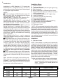
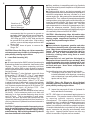
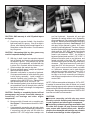
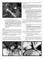
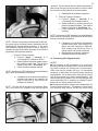
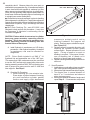
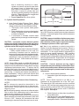
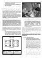
1
Instruction sheet No. 3100
Revised 11-28-95
S&S® Cycle, Inc.
Copyright ©, 1986, 1995
by S&S Cycle, Inc.
Box 215
Viola, Wisconsin 54664
All rights reserved. Printed in the U.S.A.
Phone 608-627-1497
Fax 608-627-1488
Installation of S&S Sidewinder 35⁄8" Big Bore Cylinders
for Evolution Sportster V2 Engines - 1986 and Later
SAFE INSTALLATION AND OPERATION RULES:
Before installing your new S&S stroker kit it is your responsibility
to read and follow the installation procedures in these instructions
and follow the basic rules below for your personal safety.
● Gasoline is extremely flammable and explosive under certain
conditions and toxic when breathed. Do not smoke. Perform
installation in a well ventilated area away from open flames or sparks.
● If compressed air is used during installation, be particularly careful.
Compressed air and particles dislodged by compressed air are
harmful to eyes and body. Wear protective goggles, and always direct
air stream away from body parts such as hands and eyes and other
people near you.
● When using solvents, degreasers and other chemicals during
cleaning and installation, read manufacturer's instruction label for
proper use. Exposure of some chemicals to skin, eyes and/or other
body parts may be harmful. Many items are flammable and present
a fire hazard. Use in well ventilated area and wear protective clothing
when using them to avoid personal injury.
● If motorcycle has been running, wait until engine and exhaust pipes
have cooled down to avoid getting burned before performing any
installation steps.
● Before performing any installation steps disconnect battery to
eliminate potential sparks while working on electrical components.
● Read instructions thoroughly and carefully so all procedures are
completely understood before performing any installation steps.
Contact S&S with any questions you may have if any steps are unclear
or any abnormalities occur during installation or operation of
motorcycle.
● Consult an appropriate authorized H-D service manual for correct
disassembly and reassembly procedures for any parts other than
those outlined in these instructions.
● Use good judgement when performing installation and operating
motorcycle. Good judgement begins with a clear head. Don't let
alcohol, drugs or fatigue impair your judgement. Start installation
when you are fresh.
● Be sure all federal, state and local laws are obeyed with the
installation.
● Be sure all fuel lines, supply and overflow, are routed correctly
and fuel line clamps are in place and tightened. Lines must not
contact exhaust pipes or other extremely hot surfaces where they
could melt or leak and catch fire.
● Before starting engine and riding motorcycle, be sure throttle opens
and closes smoothly. Turn handlebars to left and test throttle. Then,
turn bars to right and test throttle. To avoid possible loss of control
of motorcycle and potential personal injury to yourself or others due
to throttle sticking in open position, throttle must work smoothly
and return to a fully closed position when hand is removed from
throttle grip.
● Motorcycle exhaust fumes are toxic and poisonous and must not
be breathed. Run motorcycle in a well ventilated area where fumes
can dissipate
DISCLAIMER:
S&S parts are designed for high performance, off road, racing
applications and are intended for the very experienced rider only.
The installation of S&S parts may void or adversely effect your
factory warranty. In addition such installation and use may violate
certain federal, state, and local laws rules and ordinances as well
as other laws when used on motor vehicles used on public
highways, especially in states where pollution laws may apply.
Always check federal, state, and local laws before modifying your
motorcycle. It is the sole and exclusive responsibility of the user
to determine the suitability of the product for his or her use, and
the user shall assume all legal, personal injury risk and liability
and all other obligations, duties, and risks associated therewith.
IMPORTANT NOTICE:
Statements in this instruction sheet preceded by
the following words are of special significance:
WARNING
Means there is the possibility of injury to yourself
or others.
CAUTION
Means there is the possibility of damage to the
engine or motorcycle.
NOTE
Other information of particular importance has been
placed in italic type.
S&S recommends you take special notice
of these items.
WARRANTY:
All S&S parts are guaranteed to the original purchaser to be free
of manufacturing defects in materials and workmanship for a period
of six (6) months from the date of purchase. Merchandise that fails
to conform to these conditions will be repaired or replaced at S&S’s
option if the parts are returned to us by the purchaser within the 6
month warranty period or within 10 days thereafter.
In the event warranty service is required, the original purchaser
must call or write S&S immediately with the problem. Some problems
can be rectified by a telephone call and need no further course of action.
A part that is suspect of being defective must not be replaced by a
Dealer without prior authorization from S&S. If it is deemed necessary
for S&S to make an evaluation to determine whether the part was
defective, a return authorization number must be obtained from S&S.
The parts must be packaged properly so as to not cause further
damage and be returned prepaid to S&S with a copy of the original
invoice of purchase and a detailed letter outlining the nature of the
problem, how the part was used and the circumstances at the time of
failure. If after an evaluation has been made by S&S and the part was
found to be defective, repair, replacement or refund will be granted.
ADDITIONAL WARRANTY PROVISIONS:
(1) S&S shall have no obligation in the event an S&S part is modified
by any other person or organization.
(2) S&S shall have no obligation if an S&S part becomes defective in
whole or in part as a result of improper installation, improper
maintenance, improper use, abnormal operation, or any other misuse
or mistreatment of the S&S part.
(3) S&S shall not be liable for any consequential or incidental
damages resulting from the failure of an S&S part, the breach of any
warranties,the failure to deliver, delay in delivery, delivery in nonconforming condition, or for any other breach of contract or duty
between S&S and a customer.
(4) S&S parts are designed exclusively for use in Harley-Davidson
motorcycles. S&S shall have no warranty or liability obligation if an
S&S part is used in any other application.
2
Introduction
Installation Steps:
Installation of an S&S Sportster V2 35⁄8" bore stroker
Sidewinder Kit is comparatively easy and can be
performed by any Harley-Davidson repair shop equipped
to do complete engine overhauls.
1.
2.
3.
4.
5.
6.
NOTES
● To make installation of S&S Sidewinder series 3 5⁄8"
bore kits easier, S&S has designed several Special
Tools worth considering. They are:
Part #53-0002 - Connecting Rod Checking Pin helps check piston alignment in cylinder bore.
Part #53-0020 - Degree Wheel Kit - used to check
and set ignition timing and to check cam timing. This
kit can also be used to check crankcase breather
gear timing in big twin engines.
Part #53-0006, #53-0007 and #53-0008 - Crankcase
Boring Fixture and V 2 Crankcase Boring Spacers adapts most boring bars so crankcases can be bored
to fit larger diameter spigots on big bore cylinders.
Enables qualified operator to bore cases in about an
hour after initial setup. Can also be used to bore
pre-Evolution style Big Twin heads when installing
big bore cylinders.
Part #53-0003 l00ml Buret - used to measure
combustion chamber volume (cc heads) to calculate
compression ratio.
● S&S pinion shafts for Evolution Sportsters are
the 1987 style splined shaft because this design
is stronger than the later style stock straight shaft
and key. As a result, the engine builder must use
a 1986-1987 style pinion gear (H-D #24055-86
through #24061-86) and oil pump drive gear H-D
#26318-75. Stock Torrington style pinion main bearing
in 1986 crankcases must be replaced with 1987 style
race and later steel caged roller bearing. See Steps
6 and 10.
● Due to increased cylinder length, S&S Sidewinder
kits of 96" and larger displacement require that stock
cylinder studs be replaced with Big Twin style cylinder
studs.
Read instructions thoroughly before starting work.
When they are completely understood proceed with
installation. It is strongly recommended that the engine
builder also obtain a copy of an H-D service manual of
the same year as the engine being built.
Kit Part
Number
91-3002
91-3204
91-3206
91-3304
91-3306
91-3504
91-3506
Clearance Frame*
Crankcase Alignment
Cylinder Mounting Studs (96" and larger engines only)
Bore Crankcases
Modify Crankcases for Oil Returning from Heads
Convert Pinion Main Bearing To 1987 and Later Style
(1986 crankcases only)
7. Connecting Rod Preparation (79" engines only)
8. Lower End Assembly
9. Crankcase and Piston Skirt Clearancing
10. Connecting Rod Alignment*
11. Cylinder Head Preparation
12. Piston to Head and Piston to Valve Clearancing
13. Final Assembly and Engine Installation
14. Engine Break-In Procedure
15. Performance Notes
*NOTE - S&S recommends that engine builder consider
performing some steps during initial engine removal and
disassembly. Checking clearance between stock engine
and frame will allow an accurate estimate of amount and
location of clearancing required after kit is installed. While
entire flywheel and rod assembly may be replaced, it is
sometimes helpful to check original parts combination and
note problems that can be corrected more easily before
engine is reassembled.
Installation
1. Clearance Frame
NOTE - Piston stability in cylinder bore is improved by
using pistons with the longest possible skirts. In order to
provide a performance engine with the best possible
engine life, S&S increases the cylinder length when the
stroke is increased, rather than decreasing the length of
the piston. Frame fit, stock rocker cover to frame tubes
and/or rocker cover to gas tank clearances in taller than
stock engines must be checked and corrected if needed.
It is recommended that frame clearance be measured
before stock engine is removed from frame. The 89"
Sidewinder kit is the largest engine that will fit in a stock
frame without major frame modifications.
To check and clearance frame, perform following steps:
A. Before stock engine is removed from frame,
measure clearance between rocker boxes and
frame. Tightest spot is normally above and
behind rear head.
3-13/16"
Cylinder
Length
4.650"
Cylinder Length
Compared to Stock
Stock Length
89"
4-15/16"
5.087"
+.437"
96"
4-5/8"
5.565"
+.915"
103"
5"
5.750"
+1.100"
Displacement
Stroke
79"
Figure 1
3
B. Refer to chart in Figure 1 to determine increase
over stock engine height for the kit to be installed.
S&S recommends .100" minimum clearance
between engine and frame. If increased cylinder
height of Sidewinder kit will not leave sufficient
room, clearancing will be required. S&S V2 XL
style cylinder heads are .062" taller than stock,
so additional clearance will be required if S&S
heads are to be used.
NOTE - S&S recommends there be .100" minimum
clearance between engine and frame. Up to .060" or
.070" may be ground from rocker box cover in some areas
for clearance. If cover is ground, be careful not to break
through since covers are very thin.
CAUTION - Excessive material removed from rocker
cover may damage cover causing oil leaks.
Picture 1
Picture 1
WARNING - Removing material from welds or frame
tube may cause structural damage and possible
failure resulting in personal injury or death. If frame
must be modified, work should be done by a
professional frame shop.
CAUTION - Be careful when removing studs so as
not to damage threads in cases. If heat is applied to
case around stud to help loosen threads, do not allow
crankcase temperature to exceed 375° F as this may
destroy heat treatment of crankcase material.
C. After crankcases have been bored in Step 4,
mock up engine using Sidewinder cylinders.
Place mocked up engine in frame and
determine if additional clearancing will be
needed to provide recommended .100" space
between engine and frame.
2. Crankcase Alignment
NOTE - Some H-D crankcase base gasket surfaces on
which cylinders are positioned do not align properly. This
usually occurs when crankcase halves used are from
different crankcase assemblies and were not paired and
machined together during manufacture. It is
recommended that crankcases be checked for
misalignment even if crankcase halves are correctly
matched to prevent potential oil leaks and other
mechanical problems.
CAUTION - Mismatched gasket surfaces due to
improperly aligned crankcase halves may cause
oil leaks.
A. Clean cases thoroughly and assemble both halves
without flywheels. Tighten all case bolts as in final
assembly.
B. Place straight edge ruler across base gasket
surface. See Picture 1.
C. If crankcase halves are correctly aligned,
proceed to Step 3. If any misalignment exists
got to Step D in this section.
D. Remove cylinder studs and place masking tape
over cam and mainshaft bearings to keep chips
out. Consult H-D service manual for proper
cylinder stud removal and installation procedures.
E. Place cases squarely in mill. Base gasket
surface must be square with center line of
crankshaft and 45° from opposite cylinder base
gasket surface. Machine gasket surface taking
minimum necessary to clean surface. Repeat
for other cylinder.
F. Reinstall cylinder studs. For engines under 96"
(4 5⁄ 8" stroke) reinstal V 2 Sportster style studs.
For engines of 96" or larger install late Big Twin
style studs. (See Step 3) Consult H-D service
manual for proper stud installation procedure.
3. Cylinder Mounting Studs
96" Engines and Larger only
NOTE - S&S Sidewinder kits for Evolution Sportsters of
96" (4 5⁄8" stroke) or greater require the use of Big Twin
style cylinder studs. This is due to the increased cylinder
length in these kits.
A. Remove stock cylinder studs if this has not been
done in Step 2. Consult H-D service manual for
proper stud removal procedures.
CAUTION - Be careful when removing studs so as
not to damage threads in cases. If stud does not
come out easily, carefully heat case around stud as
heat may help loosen threads. Do not allow crankcase
temperature to exceed 375° F, as this may destroy
heat treatment of crankcase material.
B. Install late style Big Twin V2 male type studs,
S&S #31-2321 or #31-2323, or H-D part
#16837-85C. Consult H-D service manual for
proper installation procedures.
4
B.
Picture 2
4. Bore Crankcases
C.
NOTE - Boring cylinder spigot holes in cases to
accommodate big bore cylinders will machine a notch on
center case bolt. This bolt must be replaced with a special
stud which is installed into the top crankcase bolt hole in
the cam side case half.
D.
Perform following procedure to bore crankcases:
A. In 1986-1990, four speed cases, the center
crankcase bolt must be replaced by S&S stud #312046. In 1991 and later, 5 speed cases, the center
crankcase bolt must be replaced by S&S stud #312047. The stud will be installed in the threaded
hole in the camside crankcase half that the stock
center crankcase bolt normally screws into.
E.
crankcase to top of stud for 1991 and later
crankcases. If driveside case is set in place,
stud should extend far enough that there is
full thread engagement with 12 point nut
#31-5024 when washer is in place. See
Picture 3.
2. If stud can not be screwed in far enough to
obtain specified stud height, hole must be
drilled and tapped deeper. It is recommended
that this drilling operation be done on a milling
machine or drill press to avoid destroying
existing threads.
3. If stud can be installed to correct height, clean
stud and threaded hole with lacquer thinner
and install stud to correct height using red
Loctite or other permanent thread locking
compound.
Clean cases thoroughly and assemble using all
case bolts. Tighten all case bolts as in final
assembly.
Place masking tape over both ends of camshaft
and mainshaft bearings to keep chips out.
Bolt boring plate to bench or stand leaving
squared end of plate protrude over edge
approximately 7".
Using 4 3⁄8 -16 thread nuts, bolt cases to plate using
all four studs. Boring spacer, Part #53-0007, is
used to space cases using stock Sportster V2
studs. If Sportster studs have been replaced with
late, male style Big Twin studs, use both #53-0007
and #53-0008 spacers to space cases away from
boring fixture. See Picture 4.
NOTE - Be careful not to damage studs. Do not lift cases
by studs and avoid knicking, scratching or denting studs.
1. Before final installation of stud, screw stud into
hole to make sure installed height is correct.
See Picture 2. Stud should extend 2.570" 2.630" from crankcase to top of stud for 19861990 crankcases, and 2.270" - 2.330" from
Picture 3
Picture 4
5
5. Modify Crankcases for Oil Returning from Heads
NOTE - Oil return passageways in V 2 Sidewinder
cylinders are moved out slightly compared with stock oil
return holes to accommodate 3 5⁄8" bore. This creates
misalignment between cylinder oil return passage and
crankcase oil return passage.
Figure 2
CAUTION - Damaged studs may cause stress risers
which can lead to stud failure and possible damage
to engine components.
F. Center boring bar head in cylinder spigot bore in
crankcases, not hole in plate. Refer to
manufacturer’s instructions supplied with boring
bar for correct procedure.
G. Bore hole to diameter of 3.878" to 3.880" by 15⁄8"
deep. Measure depth perpendicular from cylinder
base gasket surface.
NOTE - We normally take three cuts to bore cases,
3.800" diameter, 3.850" and final size 3.879". If you
machine into boring plate on final cut, this is of no
consequence since hole in plate is never used as
machining reference point.
H. Repeat steps E to G for other spigot bore.
I. Deburr and remove any "nubs" or protrusions
which could accidentally break off. Break the
corner on outside of spigot holes with a
deburring tool. This insures that cylinder will
not "hang up" during installation causing oil
leaks due to inadequate gasket compression.
Figure 2 shows an exaggerated view.
Picture 5
To modify cases and return oil properly, perform
following steps:
A. Place cylinder base gasket on cases and note
amount and direction of return hole mismatch.
B. Chamfer edge of hole accordingly at minimum
of 45° angle to insure adequate flow. See
Pictures 5 and 6.
6. Convert Pinion Main Bearing
To 1987 & Later Style (1986 crankcases only)
A. Remove stock Torrington style pinion needle
bearing assembly. Follow procedures outlined in
1986 H-D service manual for removal.
B. Install 1987 and later style pinion bearing race
H-D #8881. Follow procedures outlined in
1987 and later H-D service manual.
C. Lap bearing race and fit bearings per procedures
outlined in 1987 and later H-D service manual.
7. Connecting Rod Preparation (79" kits only)
NOTE - If S&S connecting rods are used, follow
instructions that accompany rods since rod preparation
below has already been done. Stock rods can not be
used with Sidewinder kits larger than 79". Longer than
stock S&S connecting rods will be provided with all kits
larger than 79".
79" kit #91-3002 only - If S&S rods are not used,
perform following steps:
A. To insure adequate oil on sides of rods and
matching thrust surfaces of flywheels, S&S
Picture 6
6
Grind four oil
grooves on both
sides of forked rod
Figure 3
recommends that four grooves be ground on
each side of both front and rear connecting rods.
See Figure 3. Make these grooves .020" to
.030" deep and .030" to .040" wide and should
be ground 90° from each other. After making
grooves, remove all sharp edges and burrs with
emery cloth.
B. Thoroughly clean all parts to remove dirt,
filings, etc.
CAUTION - Burrs, dirt, filings, etc. left on connecting
rod components may circulate in oil damaging other
parts possibly causing engine failure.
8. Lower End Assembly (All)
NOTES
● All current production S&S Evolution Sportster style
flywheels are made from closed die, heat treated, steel
forgings. They do not have connecting rod thrust
washers like earlier S&S or stock flywheels, because
present flywheel material is harder than thrust washers
previously used.
● S&S Sportster V2 style flywheels come with three
timing marks, "F", "R" and "TF". The "F" mark stands
for front cylinder 30° before top dead center (TDC).
The "R" mark is rear cylinder 30° before TDC, The
“TF” mark is TDC front cylinder . When "F" or "R" mark
is placed in center of timing hole it means that cylinder
is timed at 30° before TDC. We recommend that "big
inch" Sportster engines be timed at 30-32° before TDC
rather than the stock 40 ° before TDC. See
Performance Notes, "Ignition Timing".
● Usually S&S flywheels are balanced before leaving
our facility. Some customers prefer to do their own
balancing or to have another balancing shop do the
work for them. This is acceptable in most cases.
However, we have had some bad experiences with
dynamically balanced flywheels that have forced us to
void our guarantee if flywheels have been balanced in
this fashion.
CAUTION - Flywheels assembled improperly prior to
being dynamically balanced may sustain irreversible
damage to mainshaft and crankpin tapers during
actual balancing. S&S voids its guarantee if flywheels
have been balanced in this fashion.
● Many problems in assembling and truing flywheels
can be prevented by careful inspection of all parts used
in the assembly.
● Cleaning parts prior to and during assembly and
keeping parts clean after final assembly are imperative to
minimize contaminants that may circulate in oil and
shorten engine life. Many parts can be cleaned with soap
and water first. Then, reclean all internal parts and gasket
mating surfaces using high quality solvent that does not
leave any harmful residues. Be sure to read and follow
manufacturer’s instruction label before use. Use drills
and compressed air to clean all oil passageways of dirt,
filings, etc. whenever possible. During actual final
assembly, recoat all internal parts with high quality engine
oil or assembly lube such as S&S #51-9000.
CAUTION - Manufacturing chips, dirt and/or other
contaminants circulating in engine oil may possibly
damage engine components resulting in shorter
engine life and possible engine failure.
WARNINGS
● Some solvents, degreasers, gasoline and other
chemicals are harmful to skin, eyes and other body
parts. Many items are flammable and present a fire
hazard. Read manufacturer’s instruction label for
proper use. Use in well ventilated area and wear
protective clothing when using them to avoid
personal injury.
● Compressed air and particles dislodged by
compressed air are harmful to eyes and body. Wear
protective goggles when using compressed air and
always direct air stream away from body parts such
as hands and eyes. Never direct compressed air
toward other people.
Perform following steps when assembling flywheels:
A. Thoroughly clean all parts to be used. This
includes mainshafts, main bearings, connecting
rods, rod bearings, keys and flywheels including
tapers and key ways.
CAUTION - Burrs, dirt, filings, etc. left on flywheel
assembly parts may circulate in oil damaging other
parts possibly causing engine failure.
B. Inspect key ways and oil holes in flywheels for
burrs and remove if necessary.
NOTE - S&S does not recommend lapping tapers to
remove burrs. This practice tends to distort the taper
by removing material unevenly around the
circumference. This makes flywheels difficult if not
impossible to true. In addition the lapping process work
hardens the surface of the taper. This hard surface
makes it very difficult to pull shaft or crankpin into taper.
If crankpin and shafts are not pulled fully into flywheel
tapers, excessive rod side play and assembly width
may result. Lapped flywheel tapers are also very
difficult to resurface if repairs are ever needed.
7
Picture 7
CAUTION - S&S warranty is void if flywheel tapers
are lapped.
C. Check keys in grooves of shafts. Key should be
light hand press fit in groove. If key is too tight in
groove, sand side key with fine sand paper on a
metal plate or other flat surface. Do not hammer
key into groove.
CAUTION - Hammering tight key into groove may
result in irreparable damage to shaft.
D. With key in shaft, insert into respective tapered
hole in flywheel and check to see that key does
not bottom in groove. If key bottoms out, file flat
side of key, not rounded side, until shaft with key
in place fits in flywheel without bottoming out.
Check crankpin and crankpin key also.
E. Reclean mainshaft tapers, crankpin and flywheel
tapers with lacquer thinner.
F. Assemble mainshafts in respective flywheels.
Coat taper and threads of each shaft with green
Loctite during assembly. Install crankpin in
camside flywheel using Loctite also. Tighten
crankpin nuts to 290-310 Ft. Lb. Tighten pinion
and sprocket shaft nuts to 340-360 Ft. Lb.
G. After camside flywheel, pinion shaft and crankpin
are assembled, blow air through pinion shaft oil
feed hole to check for blockage or misalignment
of oil feed passages.
CAUTION - Partially or completely blocked oil feed
passageways may cause irreversible damage to
connecting rod bearings and other engine
components.
H. Measure width of female rod on crankpin end.
See Picture 7. Measurement should be 1.481"
to 1.483".
I. A pre-assembly connecting rod side play check
should be done before final assembly to determine
if connecting rod side play will fall within the
specified .015"-.035" range when crankpin nuts
Picture 8
are final tightened. Assemble left and right
flywheels on crankpin without rods. Moderately
snug crankpin nuts. Do not worry about flywheels
being true. Measure distance between connecting
rod thrust pads on flywheels. See Picture 8. Rod
side play will be reduced by about .015" when
crankpin nut is final tightened. Therefore, distance
between flywheel thrust pads as measured in this
check must be .030"-.050" greater than female
rod width measured in Step H. For example, if
female rod measures 1.482", the distance
between flywheel pads must be 1.512"-1.532". If
difference between pad to pad distance and
female rod width is less than .030", female rod
must be surface ground on sides to provide more
clearance. Take equal amounts off each side if
more than .010" is to be removed. If more than
.050" must be removed from female rod width
or if difference between pad to pad distance
and female rod width is greater than .050" a
different crankpin should be tried. If there is
too little or too much connecting rod side play,
and different crankpins do not correct problem,
contact S&S.
NOTE - S&S recommended rod side play is .015" to .035".
If material is removed from sides of female rod, overall
width of bearing cages must be reduced so bearings and
cages are free to float with rods without contacting flywheel
thrust pads. Bearing cage side clearance of .008" to .020"
less than rod width is recommended.
CAUTIONS
● Incorrect connecting rod side play may cause
excessive rod side thrusting and potential damage
to rods, flywheels and other engine components.
● Connecting rod bearing and cage assemblies that
are wider than female rod may become damaged
upon contact with flywheel thrust pads. Abrasive
particles from damaged rod bearings may circulate
in oil and cause damage to other engine parts.
8
ups are used. Please read this entire section before
beginning work.
CAUTION - Insufficient clearance between connecting
rods and crankcases, pistons and flywheels, and
between the two pistons will cause contact and
damage to components.
Picture 9
J. Finish assembling flywheels and rods.
K. Check flywheel assembly for run out by placing
ends of mainshafts between centers. Place dial
indicators on bearing surfaces of mainshafts. See
Picture 9. True wheels as needed. S&S trues
flywheel assemblies to .0005" or less runout on
either mainshaft bearing surface. However H-D
factory specs call for .001" runout and this is
acceptable.
NOTES
● When truing flywheels, runout measurements must
be taken on mainshaft bearing surfaces. Do not take
measurements on flywheel rims. Flywheel rim will
show runout that is not a valid indication of mainshaft
concentricity.
● Do not install flywheels and final assemble crankcases
until clearances are checked in Step 9.
9. Crankcase and Piston Skirt Clearancing (All)
NOTE - Many of the clearancing operations described in
this section can be done simultaneously as the same set-
Picture 10
A. Connecting Rod Clearance - Front and rear of
flywheel cavity inside crankcases and cylinder
spigots must be clearanced for connecting rods.
See Pictures 10 and 11. Procedure to check
these points is performed as follows:
1. Mock up flywheel assembly in right crankcase
half with bearings, etc. in place.
2. Assemble pistons without rings on their
proper connecting rods, and place
connecting rods on crankpin. Installation
of wristpin clips is not necessary.
NOTE - All S&S Sidewinder kits have piston to piston
clearance notch cut in the front skirt of rear piston. Rear
piston must be installed with notch toward the center
of engine.
3. Install both cylinders and secure each with
one head bolt.
4. Rotate flywheel until rods contact areas to be
clearanced. Note angle that must be filed.
5. Disassemble cylinder and connecting rods
and file crankcase and cylinder spigot for
clearance. See Picture 12.
NOTE - A minimum of .060" clearance is required between
connecting rods and crankcase and cylinder spigots.
6. Reassemble and check clearance.
7. Mark and grind other crankcase half to
identical clearance.
B. Piston Clearance - Piston clearances must be
checked to avoid piston to piston contact and
piston to flywheel contact. See Pictures 13
and 14.
Picture 11
9
operation. For this reason, piston to piston clearancing is
done on the front skirt of the rear piston in order to leave
the rear skirts of both pistons as long as possible.
e. Reassemble and recheck clearance.
2. Piston to Flywheel Clearance
a. Perform Steps 1 through 3 in
“Connecting Rod Clearance” above.
b. Rotate flywheel to position where front
piston is closest to flywheel. This is at the
bottom of the stroke. See Picture 14.
c. Check clearance between piston and
flywheel.
Picture 12
NOTE - Pistons are normally preclearanced in S&S kits,
but good engine building practice demands that all
clearances be checked during assembly. In the event
that additional clearancing must be done, weight of
material removed from pistons generally is too small to
significantly affect flywheel balance.
1. Piston to Piston Clearance
a. Perform Steps 1 through 3 in
"Connecting Rod Clearance" above.
b. Rotate flywheel to position where pistons
are closest to each other. This is at the
bottom of the stroke. See Picture 13.
c. Check clearance between pistons.
NOTE - A minimum of .060" clearance is required between
piston skirts and flywheels at the bottom of stroke where
pistons are closest to flywheels.
d. If clearance is not sufficient, disassemble
cylinder and piston, and carefully file
piston skirt until clearance is obtained.
Skirt of piston may also be fly cut on a
milling machine to provide clearance.
e. Reassemble and recheck clearance.
f. Repeat procedure for rear piston.
10. Connecting Rod Alignment (All)
NOTE - The rear skirt of the piston is the primary thrust
face, and carries the greatest load during engine
NOTES
● The purpose of this procedure is to correct for
machining tolerance discrepancies in components which
may lead to pistons not running true in cylinder bores.
While rods may be straight and true, it is sometimes
necessary, to bend them to correct for these machining
discrepancies. Do not bend rod by using tool in wristpin
hole as this method may distort wristpin bushing. We
also feel that using a piston in lieu of a checking pin may
prove inaccurate due to variations in lengths of piston
skirts from one side of piston to the other.
● All engines should be checked upon disassembly for
incorrect piston alignment. This applies to those which
are receiving new pistons as well as those being
Picture 13
Picture 14
NOTE - A minimum of .060" clearance is required between
piston skirts at the bottom of the stroke.
d. If clearance is not sufficient, disassemble
cylinders and pistons, and carefully file
notch in front skirt of rear piston until
clearance is obtained.
10
completely rebuilt. Observe pistons for wear spots on
sides above top compression ring. If one side near wristpin
is worn clean while side opposite is carboned up, then
piston was not running straight and true in cylinder bore.
Piston will also generally show diagonal wear pattern on
thrust faces of skirts and possibly signs of connecting rod
to wristpin boss contact inside piston.
● We feel that not enough emphasis is given to checking
piston alignment in cylinder bore. Proper piston alignment
means connecting rods will thrust to sides less minimizing
added stress on pistons, rings, rod bearings and other
related parts.
● S&S Rod Checking Pin, part #53-0002, was
designed to help perform this procedure. It may also
be necessary, to fabricate a rod bending tool as
illustrated in Figure 4.
CAUTION - Pistons which do not run true in cylinder
bores may cause excessive connecting rod side
thrusting. This in turn may lead to premature ring,
piston, connecting rod and rod bearing wear and
eventual failure of these parts.
A. Install flywheels in crankcases per H-D factory
procedures. After flywheel assembly is installed
in crankcases, rods must be checked for
straightness.
NOTE - Pinion Shafts included in all S&S V 2 XL
flywheels kits and assemblies are of the 1987 type.
This means that 1986 crankcases must be converted
to use the 1987 and later style caged roller pinion main
bearing assembly, and that 1986 -1987 style pinion gear
and oil pump drive gears must be used in 1988 and
later engines. See Step 6.
B. Checking Pin Procedure
1. Insert checking pin into wristpin hole.
Place strips of paper between checking
pin and crankcase cylinder gasket
surface and apply slight downward
Picture 15
.510"-.520" Wide Slot
11/8"
4"
22"
1 1 /4 "
Figure 4
pressure to wristpin end of rod by
rotating flywheels. Pull papers out
slowly. Drag on papers should be equal.
See Picture 15.
2. Rotate flywheels in opposite direction until
checking pin contacts cylinder gasket
surface again. Repeat procedure to rod
again. If drag on papers is equal no
bending is required. If one paper is loose,
use rod bending tool to tweak rod in
direction of loose paper and recheck.
3. Repeat checking and bending procedure for
other rod.
C. Visual Procedure
1. Install pistons on rods without rings or wristpin
clips. Bolt cylinders with gaskets in place.
2. Move piston tight towards camside of engine.
3. Turn engine over in normal direction of
travel 2 or 3 revolutions and observe
piston during process.
4. Move piston towards driveside of engine and
repeat Step C. If inaccuracies are present
Figure 5
11
due to machining variations in cases,
cylinders or pistons, top land of piston deck
will appear closer to cylinder wall at one
point around circumference. This means
that piston is cocked in cylinder bore and
can be corrected by bending rod in opposite
direction. Figure 5 shows an exaggerated
side view of this condition.
5. Repeat Steps B to D for other cylinder.
Piston Deck
Deck Height
Wrist Pin Hole
11. Cylinder Head Preparation
A. Head Gasket Surface Flatness Check - Before
top end is assembled, head gasket to cylinder
mating surfaces should be checked as follows
1. Thoroughly clean cylinder head gasket
surfaces.
2. Place straight edge ruler across head gasket
surface at different places around diameter
to determine flatness.
3. If unevenness is revealed, machine head
gasket surface just enough to make complete
contact.
CAUTION - Incomplete contact between gasket
surfaces of cylinders and cylinder heads may cause
combustion leakage possibly resulting in damage to
cylinders and/or other engine components.
B. Modify 883 Cylinder Head Combustion Chamber
- If 883cc cylinder heads are to be used, the
combustion chambers must be modified to
improve air flow and reduce the compression ratio.
Follow enclosed Instruction Sheet #3883 or #3884
depending on style of combustion chambers in
heads to be used. 1200cc heads do not require
this modification.
NOTE - Stock 1200cc heads or modified 883 heads will
provide a usable compression ratio but the small valves
and ports in stock heads will be a limiting factor for a large
displacement performance motor. To achieve the full
potential of the engine it is recommended that the size of
the valves be increased and the ports modified to further
improve flow. In weighing the expense and difficulty of
these modifications, it may be more cost effective and
results intensive to use S&S or other aftermarket
performance heads.
12. Piston to Head & Piston to Valve Clearancing
NOTES
● The clearancing operations described in this
section can be done simultaneously as the same setups are used. Please read this entire section before
beginning work.
● All valve spring spacing, rocker arm to collar and rocker
arm to rocker cover clearancing must be done before
piston to valve clearancing can be checked.
● S&S flat topped pistons have sufficient valve clearance
when used with most street high performance cams with
lifts up to .525". However, we recommend that valve
clearancing be checked if other than stock cam is used.
Figure 6
● If S&S cylinder heads and pistons are used, cams of
up to .560" lift can be run without valve to piston clearance
problems. If cams with higher lift are used this clearance
must be checked.
CAUTION - Improper installation of pistons may cause
unwarranted stress, premature wear and/or contact
with each other or other engine components resulting
in damage to pistons or other engine parts.
● If there is any resistance or contact at any point in
rotation it must be diagnosed and corrected. Since it is
nearly impossible to anticipate every possible engine
combination, it is the engine builder’s responsibility to
check for proper running clearances. S&S considers
checking and establishing all running clearances as
standard engine building practice that must be performed
during engine assembly. Engine failure due to improper
clearances between moving parts is not covered under
warranty.
CAUTION - Contact between moving engine
components may cause damage or destruction of the
parts involved and produce abrasive particles which
may cause damage or premature wear to other engine
components.
A. Piston to head (squish) clearance
1. Assemble engine with exception of cylinder
heads.
NOTE - Pinion Shafts included in all S&S V 2 XL
flywheels kits and assemblies are of the 1987 type.
This means that 1986 crankcases must be converted
to use the 1987 and later style caged roller pinion main
bearing assembly, and that 1986 -1987 style pinion gear
and oil pump drive gears must be used in 1988 and
later engines. See step 6.
2. Rotate flywheels so front piston is positioned
at top dead center.
3. Note where piston deck (See Figure 6, piston
deck diagram) is positioned in relationship to
head gasket surface. Piston deck (flat located
12
just above top compression ring groove), not
dome, must be flush with or slightly below
gasket surface.
4. If piston deck is higher than cylinder at top
dead center, something is wrong and S&S
should be notified. If piston deck position is
correct proceed to Step B.
NOTE - Most stock V 2 and S&S V 2 style engines are
designed with .045" to .062" piston to head clearance.
This clearance is provided by thickness of head gasket.
Therefore at top dead center, piston deck should be
flush with or slightly below head gasket surface of
cylinder. Cylinder base gasket must be in place when
this check is made.
CAUTION - Insufficient clearance between piston
domes and cylinder heads will cause damage to
pistons and heads.
B. Piston to Valve Clearance
1. Turn engine over until piston in front cylinder
is at top dead center. Paint area around valve
pockets on pistons with machinist’s blue.
2. Place valves in cylinder head leaving off
springs and retainers. Place head on cylinder
and secure with one bolt.
3. Lower valves until they contact piston. Rotate
valve marking painted area.
4. Remove head and check points of contact.
Valve should fit in recessed area machined in
piston dome.
NOTE - S&S recommends at least .060" clearance around
periphery of valve.
5. If insufficient clearance exists, remove piston
and grind valve pocket until head of valve fits
flush with proper clearance. Clean parts
thoroughly before reassembly.
CAUTION - Do not remove more material than needed
when performing piston to valve clearancing.
Removal of excessive amounts of material may
weaken top ring land of piston causing piston
breakage and serious engine damage.
6. Repeat procedure for other cylinder head.
7. Spread layer of putty into valve pockets in
both pistons.
8. Assemble cylinder heads and bolt
assemblies on cylinders with head gaskets
in place. Install pushrods and adjust to
simulate final assembly.
NOTE - If hydraulic lifters are used, pushrods should be
adjusted so that lifters are completely collapsed for this
test. This will insure that lifters do not collapse due to
valve spring pressure, and that full valve lift is achieved.
9. Turn engine over in normal direction of travel
two complete revolutions.
10. Remove cylinder heads and check thickness
of putty in valve pockets.
11. If clearance is sufficient, disassemble top end
and proceed to final assembly.
12. If less than .060" clearance in any area exists,
remove piston from engine and grind area until
proper clearance is achieved. Clean parts
thoroughly before reassembly.
NOTE - S&S recommends at least .060" clearance
between valve and piston valve pocket recess. While
.060 clearance is recommended minimum, it is advisable
to have more, if possible.
CAUTION - Insufficient clearance between piston and
valves may cause them to contact each other during
operation resulting in damage to piston and valve
train components.
13. Final Assembly and Engine Installation
NOTE - Cleaning parts prior to and during assembly and
keeping parts clean after final assembly are imperative to
minimize contaminants that may circulate in oil and
shorten engine life. Many parts can be cleaned with soap
and water first. Then, reclean all internal parts and gasket
mating surfaces using high quality solvent that does not
leave any harmful residues. Be sure to read and follow
manufacturer’s instruction label before use. Use drills
and compressed air to clean all oil passageways of dirt,
filings, etc. whenever possible. During actual final
assembly, recoat all internal parts with high quality engine
oil or assembly lube such as S&S #51-9000.
CAUTION - Manufacturing chips, dirt and/or other
contaminants circulating in engine oil may possibly
damage engine components resulting in shorter
engine life and possible engine failure.
WARNINGS
● Some solvents, degreasers and other chemicals
are harmful to skin, eyes and other body parts. Many
items are flammable and present a fire hazard. Read
manufacturer’s instruction label for proper use. Use
in well ventilated area and wear protective clothing
when using them to avoid personal injury.
● Compressed air and particles dislodged by
compressed air are harmful to eyes and body. Wear
protective goggles when using compressed air and
always direct air stream away from body parts such
as hands and eyes. Never direct compressed air
toward other people.
A Spin each head bolt down on its respective stud
to be sure threads are clean and free of
contamination.
B. Install cylinder base gaskets provided dry. Be sure
gaskets match cylinder base line-up dowels and
oil return passageways.
13
C. Install pistons, rings and wristpin clips per S&S
piston instruction sheet #2500.
D. Coat piston skirts with engine oil or assembly lube
and install cylinders.
E. Place o-ring seals over cylinder head alignment
dowels. Install head gaskets provided in kit dry.
NOTE - Care must be taken to use correct alignment
dowel o-rings with V 2 head gaskets. Head gaskets
supplied with S&S cylinder heads compress to about .045"
thick and require .070" diameter o-rings. Gaskets supplied
with SIDEWINDERS for stock heads compress to about
.0625" and require .0825" diameter o-rings.
CAUTION - Using thin o-rings with thick gaskets or
thick o-rings with thin gaskets may cause oil leaks or
possible ruptured head gaskets around line-up
dowels due to incorrect o-ring compression.
Picture 16
NOTE - All S&S cylinder head kits are supplied with .045"
thick head gaskets, because this clearance promotes
better combustion chamber turbulence and flame travel.
When other cylinder heads are used S&S supplies .0625"
thick gaskets. Using thicker head gaskets with S&S heads
reduces design efficiency and performance. If thinner
head gaskets are used with other cylinder heads, piston
to head and valve to piston clearances must be checked
during assembly.
stages using crossing pattern. See Figure 7.
If using S&S crankcases, torque bolts to 45-47
ft. lbs. in four stages. If using stock crankcases,
follow the same bolt tightening sequence, but
use stock three stage procedure and torque
values shown in Figure 7. If using other
aftermarket crankcases, contact the
manufacturer for recommended head bolt
torque specifications.
CAUTION - Insufficient clearance between piston
domes and cylinder heads or piston domes and
valves will cause damage to pistons, heads and/
or valves.
NOTE - Light coating of oil on head bolt threads
minimizes friction so torque values are not distorted. It
cannot be emphasized enough how important it is to
do these steps carefully. Maintaining a good head
gasket seal depends on it.
F. Bolt heads on cylinders. Place one or two drops
of oil on threads of each head bolt just prior to
final assembly to reduce friction and insure
accurate torque readings. Tighten bolts in
Top View
Driveside
2
1
Rear Head
3
1
2
Front Head
4
4
3
Camside
Stage 1
Stage 2
Stage 3
Stage 4
S&S Crankcase
10 Ft. Lbs.
22 Ft. Lbs.
35 Ft. Lbs.
45-47 Ft. Lbs.
Figure 7
Stock Crankcase
7-9 Ft. Lbs.
12-14 Ft. Lbs.
Turn additional 90°
CAUTION - Improper torquing sequence and head bolt
torque values may cause head gasket failure.
Excessive torque values may cause studs to pull out
of crankcase.
G. Finish Assembling Top End
1. Install rocker arm bases per H-D specs.
2. 1991 And Later Five Speed Models Only Stock one piece pushrod tube assemblies
on 1991 and later five speed engines must
be replaced with 1986 to 1990 style two
piece pushrod tubes to allow adjustment of
pushrods. Installation of #33-5360 S&S
pushrod tube adapter provides cup for
bottom of earlier style pushrod tubes. Place
stock pushrod retainer over small end of
adapter. Slide stock pushrod seal on small
end of adapter. Install adapter, retainer, and
seal over tappet bore in crankcase with
stock bolt and washer. Do not final tighten.
See Picture 16.
3. Assemble rocker arms, pushrods and pushrod
tube assemblies and adjust pushrods. For
1991 and later five speed motors, place
bottom end of 1986 to 1990 style pushrod
14
Manifold
Flange
O-ring
Figure 8
tubes in cup of adapter. Use stock 1986 to
1990 pushrod seals. Rotate S&S pushrod
tube adapters so that cup surface is as close
to perpendicular with pushrod tube as
possible. Install pushrod cover clip and final
tighten stock pushrod tube retainer bolt.
4. Install rocker covers and gaskets.
5. Install intake manifold, mounting flanges
and o-ring seals. Be sure o-rings and
flanges are assembled in correct sequence.
Tapered side of o-ring must fit into tapered
side of flange. See Figure 8. Use flange
marked “F” on front head and flange marked
“R” on rear . Slotted end of mounting flange
goes toward lower manifold mounting hole.
Flat washer provided is used on slotted end
of flange. Do not tighten mounting flange
screws.
NOTE - If S&S heads are installed, special S&S
manifold must be used because intake port diameters
of S&S heads are larger than stock. Special S&S
manifold requires o-ring seals which also have larger
than stock diameter to fit O.D. of manifold runners.
These o-rings, S&S part #16-0235, are included and
cannot be used in stock applications.
CAUTION - Incorrect o-ring seal may cause air leaks
around manifold resulting in lean condition and
possible damage to engine.
H. Bolt carburetor and air cleaner assembly in
place using carburetor instructions supplied
from manufacturer. Final tighten manifold
mounting flanges.
NOTE - Some builders may prefer to install carburetor
after engine is installed in frame to reduce the possibility
of damage to carb.
I.
Install engine in frame according to H-D factory
procedures.
NOTE -The stock head mounts when used on Sportster V 2
Sidewinders with longer than stock cylinder lengths will be
short. Use the special S&S head mounts provided.
J. Reassemble gas tanks and all other parts that
were dissembled during preparation for top end
service. Be sure there are no gasoline leaks
and that throttle opens and closes smoothly and
snaps shut when released.
NOTES
● Throttle must not bind and must snap shut to fully
closed position when released.
● Fuel needle and seat assembly must completely shut
off fuel supply entering bowl. Fuel line connections
must not leak.
CAUTION - Unwarranted gasoline leaking by fuel inlet
needle may flood engine causing damage to
components.
WARNINGS
● If throttle does not return to fully closed position
when released, it may inadvertently stick open
possibly causing loss of control of motorcycle and
personal injury to you or others.
● Unwarranted gasoline leaks at fuel line
connections and/or past inlet needle may flood engine
and overflow on surrounding area creating fire
hazard.
14. Engine Break-In Procedure
A. Upon initial start-up, quickly check to make sure
oil pressure is normal and no leaks exist. With
minimal load on engine, ride motorcycle at low
speeds until cylinder head temperature reaches
about 250°. Do not crack throttle or subject engine
to any heavy load during this period as V2 head
gaskets are susceptible to failure until heat buildup is completed. Heat build-up is necessary to
cause heads and cylinders to expand and seal.
15
Improper initial engine start-up and break-in
procedure may cause head gasket failure.
NOTE - Proper first time engine start-up and break-in is
critical to achieve permanent and lasting head gasket seal.
Prior to initial start-up, a .001" to .005" feeler gauge will fit
between head gasket and head and cylinder gasket
surfaces stopping at fire ring on head gasket. Warming
engine as instructed will tightly close this gap producing a
good, lasting seal.
CAUTION - Do not allow engine temperature to
become excessive as permanent engine damage
may result.
B. First 50 miles are most critical for new rings
and piston break-in. Most engine damage will
initially occur during this period. Keep heat
down by not exceeding 2500 rpm. Vary speed.
Do not lug engine.
C. Next 500 miles should be spent running engine
no faster than 3500 rpm or about 50-55 mph. Do
not lug engine and continue to vary speed.
CAUTION - Lugging or running engine prematurely
at high rpm’s may result in damage to pistons and/or
other engine components. S&S voids its guarantee
if engine is not broken in properly.
D. For balance of first 1000 miles, speed can be run
up to 60 to 70. Continue to run engine at all
different speeds including lower 40-45 mph
ranges.
E. 1000 to 2000 miles—basically same procedures
as before. You can be a little more liberal with
rpm range. Avoid overheating engine and putting
any hard strain on engine (drag racing, trailer
towing, sidecar operation).
G. 2000 miles and up—have fun!
15. Performance Notes
Ignition
● Ignition system type - Most S&S engines initially tested
on our dyno are equipped with a point type ignition system
or an aftermarket high performance electronic unit. These
systems allow us to bypass the performance parameters
(such as the rpm limiter) designed for stock parts and
built in to the stock ignition system. We use an other than
stock system to establish some baseline comparisons and
determine the maximum horsepower potential a given
engine combination possesses. For "real world"
evaluations and comparisons with stock combinations we
will often use a stock electronic system with an H-D
accessory performance ignition module, because more
often than not this is what is already installed. Besides,
since you already own it, the stock system is free and,
under normal operating conditions, works very well with
little or no maintenance - two requirements for satisfactory
riding. We recommend a stock ignition system for most
applications and the other systems for maximum efforts
where getting every ounce of horsepower is more
important than economizing. If the stock electronic system
is retained, contact your local H-D dealer for the part
number of an ignition module with specifications that
coincide with your high performance requirements.
● Spark plugs - Use spark plugs that are compatible with
the ignition system. If you are in doubt, most
manufacturers can recommend which plugs they prefer
you use with their system. Dual plug installations in S&S
Super Stock heads are not necessary.
● Flywheels - S&S flywheels for V 2 Sportsters have
timing marks for front and rear cylinders. Both flywheels
have timing marks to accommodate both four speed and
five speed engines. The "F" mark is front cylinder 30°
advanced (before TDC). The “R” mark is rear cylinder
30° advanced. When "F" or "R" timing marks are located
in the center of the timing hole, the crankshaft is positioned
30° before TDC for that cylinder. Placing the mark to the
rear of the hole, or just entering the hole, advances timing
almost 5°. Conversely, if the mark is just leaving the hole,
timing is retarded almost 5°.
● Timing - Tests conducted using S&S Super Stock
heads and modified stock H-D heads showed that best
performance was achieved with the ignition timing set
between 30-32° before TDC. We attribute this to the
higher compression ratios generally used, improved flow
characteristics and improved overall efficiency. If using
stock heads, the higher the compression ratio less
advance is generally needed. Lower compression
engines may require more advance.
Some
experimentation may be required to determine the best
timing setting for best performance. Once the engine is
timed and operating, monitor it for excessive heat. Too
much heat can mean that timing is set incorrectly and
should be adjusted to prevent engine damage.
CAUTION - Improper ignition timing may cause
excessive engine heat which may damage pistons
and/or other engine components.
Carburetion
● All S&S test engines are run using S&S carburetors.
S&S Super E and G carburetors are recommended for
most applications with the Super G being used more often
on larger displacement, freer breathing engines with higher
compression ratios. Typically, engines equipped with S&S
heads require the same or slightly leaner jetting than those
engines fitted with stock heads. Consult the carburetor
jetting instructions for specific jetting recommendations.
● If another type carburetor is used, it must be made to
run rich enough to operate properly and to prevent engine
damage. If you have a problem with another carburetor,
S&S cannot help you and recommends you call the carb
manufacturer with any questions you may have.
● If the motorcycle is used exclusively on a drag strip
where engine temperatures vary, slightly richer jets may
be necessary for best performance. Larger jets/richer
mixtures will enable one to run a colder engine which is
sometimes desirable. This is best determined by
experimentation.
16
● Carburetor jetting and spark plug color - While spark
plug color may be used to help determine carburetor
jetting, S&S recommends that our instructions be used
as primary jetting guide and that plug color indications be
used only as secondary aid. We have found that different
brands of gasoline, gasoline additives, engine heat (due
to ignition timing), and brands of plugs and heat range
used distort plug color drastically making plug reading
difficult for the average tuner. Also, new plugs usually
require a road test of 10 miles or more to properly
develop the color which means that quarter mile tests
may not be long enough and hence, not always a good
indication of carb jetting. It is best to use proven spark
plug combinations and to consult the spark plug
manufacturer if you have questions. If one desires to
become more proficient at plug reading, Champion
Racing Division has a very informative booklet which
may be helpful. For details, write:
Champion Spark Plug Co.
PO Box 910
Toledo, OH 43601
● Cams and exhaust systems can make some engines
difficult to carburate. We have found that certain cams
and exhaust systems will cause poor performance at a
specific rpm, and attempts to correct jetting for that
specific level usually destroys carburetion over the
balance of the range. A combination of cam overlap,
reversion, and back pressure, or even lack of back
pressure can cause mixture dilution at certain engine
rpm’s. This dilution will cause engine roughness or
misfiring when engine is held in this range.
Exhaust Systems
● Drag pipes - While drag pipes can be used with good
results to establish performance guidelines on preEvolution engines, they are generally not recommended
for Evolution motors in street applications. Evolution
engines are easier to carburate with muffled systems.
● Muffler systems - Most stock and many aftermarket
exhaust systems are too restrictive and made exclusively
for looks with little consideration given to performance. A
very good, economical street system for V 2 engines
consists of the stock header pipes with the crossover tube
and a set of low restriction mufflers. Harley-Davidson
offers a series of mufflers that can be used with stock
header pipes that work very well in most situations and
offer an inexpensive alternative to a new exhaust system.
We prefer their tapered and baloney cut styles. This
combination will typically produce 10 hp more than drag
pipes in the midrange. Since the midrange is where the
vast majority of normal driving occurs, it makes this system
ideal for the street.
Gearing
● Gearing depends on the total weight of the machine
and rider's, the size of the engine, cams, exhaust
system and type of riding to be done. Most high
performance engines, and particularly those with larger
displacements, are capable of pulling more gear. We
suggest you break the engine in with stock gearing to
minimize the load on the engine. After the engine is
broken in you will have a better feel of its potential and
can change gearing accordingly.
● For those who wish to determine their final drive gear
ratio, refer to the formula shown below:
Ratio is engine revolutions per one rear wheel revolution.
Ratio =
(Clutch Sprocket*) X (Rear Wheel Sprocket*)
(Motor Sprocket*) X (Transmission Sprocket*)
*number of teeth on each sprocket
Compression
● Generally speaking, Evolution engines with the proper
camshaft selection can operate using higher compression
ratios with fewer problems than their earlier counterparts.
Keep in mind, though, that while engines with higher
compression ratios make more horsepower and perform
better, they also tend to lose that performance edge faster,
require more maintenance and start harder. As a rule,
we prefer to limit the compression ratio to no greater than
about 10 to 1 for engine combinations used in normal
street operation. A word of caution is in order. Before
building an engine you may regret later on, carefully
consider your riding needs, riding style and overall
performance objectives.