1
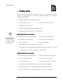
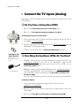
MODEL
MAGNUM
Hardware
Installation Guide
VIDABOX™ – MAGNUM™
Hardware Installation Guide
© VidaBox LLC
Support: http://www.vidabox.com/support
ii
Table of Contents
Introduction
4
Connect the Video Output
Which Video Output/Cable Are You Using?
CHAPTE R 1
OVERVIE W
How to Best Use This Guide
5
Parts List
6
Standard Accessories
6
Optional Accessories
6
CHAPTE R 2
INSTALL ATION
7
VidaBox™ Placement
8
Connect the:
Power Cable
8
Wireless Keyboard Receiver
8
Remote Receiver
8
FM Antennas
8
LAN Port
8
Touchscreen VGA Cable
9
Wireless USB Networking Module (Optional)
9
Connect the TV Inputs
Do You Have a Set-top Box (STB)?
Connecting Directly from a Coaxial cable 10
How Many STBs Do You Have?
10
Connecting a Splitter
10
How Did You Connect the TV to the STB?
11
Connecting from a Coaxial Cable
11
Connecting from S-Video/RCA Cable
11
Connect the HDTV Inputs (Optional)
13
Connecting via DVI/HDMI
13
Connecting via Component
13
Connecting via S-Video
14
Connecting via Composite
14
Connecting via Coaxial
14
Which Audio Output/Cable Are You Using?
12
15
15
Connecting via Analog Sound
15
Connecting via Digital Sound
15
Connect the Wireless Keyboard
16
CHAPTE R 3
POST INSTALL AT ION
The Next Step
17
CHAPTE R 4
SERVICE INFORMATION
Service Information
10
13
Connecting via VGA
Connect the Audio Output
VidaBox™ Diagrams
13
18
Contact your Dealer/Place of Purchase
18
Contact VidaBox LLC
18
I N T R O D U C T I O N
MODEL
MAGNUM
Introduction
Congratulations on your purchase of the VidaBox MAGNUM™! You have
made an investment in attaining a state-of-the-art audio and visual experience for
your home!
T
he VidaBox™ is the culmination of research in the latest home audio and
visual technology.
This “all-in-one” device combines the functions of multiple home entertainment
components, such as a DVD player, a CD/MP3 player, a computer, and TiVo® box
into one, easy-to-use appliance (unit).
Every VidaBox™ is preconfigured for easy installation and minimal setup time.
Everything works right out of the box.
All of our systems are fully featured, providing an unmatched digital experience.
and encourage you to read
through this comprehensive installation guide if you decide to install it yourself. Please
be sure to check out our website and support forum, where new features, questions,
and answers are available everyday.
We hope you enjoy using your VidaBox MAGNUM™,
Enjoy your VidaBox™ and have a great entertainment experience!
Sincerely,
Steven W. Cheung
Owner
Sergio DeAlbuquerque
Owner
4
O V E R V I E W
How to Best Use This Guide
I
n order to avoid improper installation, we recommend that you read through this
guide and follow the setup steps carefully.
I C O N
K E Y
New Section
Checklist Items
Valuable Information
Answer Before
Proceeding
Move on to the next
section
Keyboard Required
Please pay close attention to these icons. They alert
you to key pieces of information that are needed for a
successful installation of the VidaBox™.
If your system is professionally installed, the
installation technician should go over the main features
of the VidaBox™ with you. Keep this booklet as a
reference guide in case it is needed in the future, and
read over the User's Guide next.
We hope you enjoy using your VidaBox MAGNUM™,
and encourage you to read through this comprehensive
installation guide if you decide to install it yourself.
Please be sure to check out our website and support
forum, where new features, questions, and answers are
available everyday.
FILL IN AND SAVE
Look in the rear of your VidaBox™ and locate the serial number & Windows Product
Key. Write it here and retain it for future reference.
Serial No.
__________________________________________________
Date of Purchase
__________________________________________________
Windows
Product Key:
__________________________________________________
5
O V E R V I E W
Parts List
Please check and make sure all of the parts below are in your box before getting
started. See the Packing List to find which optional accessories came with your
VidaBox MAGNUM™.
VidaBox MAGNUM ™ Unit (Black or Silver)
This Installation Guide
Software Configuration Guide
Comprehensive User’s Guide
MAGNUM ™ Quick Hardware Installation Guide
Standard & Optional Accessories – Check List below
Standard Accessories
Missing Parts?
Don’t panic!! Simply call
the dealer or your place
of purchase immediately
and someone will be
able to assist you.
Standard 120V 3-prong Power Cable
Microsoft Media Center Remote
High Quality 6’ S-Video Cable
Two (2) DVI-to-VGA Adapters
Two (2) IR blasters
Two (2) AA batteries
High Quality 6’ 3.5mm to L/R RCA Audio Cable
Wireless RF keyboard with integrated trackball & storage sack & receiver (33’ range)
TV-Out Dongle – for S-Video, Component Video Outputs
Optional Accessories
Harmony® Programmable Remote
Wireless USB Networking Adapter
1-to-2 Coaxial Cable splitter
Two (2) Short Coaxial cables
Two (2) FM antennas
Two (2) S-Video/RCA TV-in Plugs
Karaoke Kit 400 or Karaoke Kit 900 – 400 or 990 songs with songbook
Wireless Microphone Kits - Two (2) microphones with integrated mixer
HDTV: Additional 1-to-2 Coaxial Splitter with two (2) Short Coaxial cables
6
I N S T A L L A T I O N
VidaBox Diagrams
Please take some time to familiarize yourself with the MAGNUM™ before proceeding.
A Firewire Port
H DualHD, Blu-ray, HD DVD, or DVD±RW Drive
B USB 2.0 Ports
I Disc Tray Eject
C Flash
Multi-card Reader
J Indicator Lights
D Touchsreen
Display
E Hidden Stylus
Slot
K Touchscreen Motor
Button (Tilt & Retract)
F Power Button
G Touchscreen
Power Button
S DVI
Out
R Component &
S-Video Outputs
L Parallel Port
FM Antenna In
X IR Blaster Outputs
M P/S 2 Mouse
TV Coaxial Inputs
N Power Override
Y Touchscreen VGA
Feed (connected)
O 230V/120V
Power Input
ATSC HDTV
OTA Inputs
P P/S 2 Keyboard
V SPDIF
Optical-Out
T RS-232 Port
A FireWire Port
We recommend
that the VidaBox™
be professionally
installed to yield
the best possible
audio-visual
experience.
B USB 2.0 Ports
U SPDIF-Coaxial Out
S-Video &
Composite Video Inputs
L/R RCA
Audio Inputs
W LAN Ports
FIGURE 1.0 – VIDABOX MAGNUM™ FRONT & BACK PANELS
Please familiarize yourself with the Quick Hardware Installation Guide and its
diagrams before proceeding.
7
I N S T A L L A T I O N
VidaBox™ Placement
Help! My Parts
Look Different!
These pictures are for
illustration only. The parts
in your box may look
slightly different.
The VidaBox™ should be placed in a well-ventilated area. This will help facilitate the
exchange of heat out of the system, thereby minimizing operating fan noise. At a
minimum, any area with a fan grille should have about four (4) inches of clearance.
This will allow fresh air to circulate through the MAGNUM™.
Connect the Power Cable O
Connect the Power Cable into the O Power Input; make sure it is plugged in securely.
Power Cable
Connect the Wireless
Keyboard Receiver B
Wireless Keyboard Receiver
Then, connect the USB keyboard receiver into any available USB port. The keyboard
receiver should be placed in an open area for best performance. Like the wireless
module, you will want to connect it in the back B USB Ports using the included USB
extension cable.
Connect the FM Antennas
FM Antennas
Connect the included FM Antennas into the
are connected securely.
FM Antenna Input. Make sure they
Connect the LAN Port W
CAT-5 Ethernet Cable
If you have a hard line internet connection available, you can connect to it directly with
a CAT-5 Ethernet cable to the W LAN Port.
8
I N S T A L L A T I O N
Connect the Touchscreen VGA
Cable S & Y
Short VGA Jumper Cable
•
Non-CableCARD systems:
Connect one end of the VGA jumper cable into the Y Touchscreen VGA Feed, and
connect the other end to the VGA end of the included DVI-to-VGA video adapter.
Next, connect the DVI side of the video adapter into one of the two S DVI Out ports
to complete the touchscreen’s video feed.
•
DVI-to-VGA Adapter
CableCARD systems*:
Connect one end of the VGA jumper cable into the Y Touchscreen VGA Feed, and
connect the other end to the VGA end of the included DVI-to-VGA video adapter.
Next, connect the DVI side of the video adapter into one of the two ports of the
included 1-to-2 DVI splitter module to complete the touchscreen’s video feed.
* - Note: Contact the factory for the latest instructions on CableCARD installations, as
techniques and methodologies change constantly for this cutting-edge technology.
Connect the Wireless USB
Networking Module B (Optional)
Wireless / WiFi module
Simply stick the wireless module into any available USB port. For optimum
connection, you can use the included USB extension cords to connect it to the rear
B USB Ports, so that it is hidden.
* - All pictures shown are for illustration purposes only. Actual product appearance
may vary.
9
I N S T A L L A T I O N
Connect the TV Inputs (Analog)
Depending on your TV provider source, you may connect the TV inputs in one of the
following ways:
Do You Have a Set-top Box (STB)?
1. No – Go to Connecting Directly from a Coaxial Cable below.
2. Yes – Go to
How Many Set-top Boxes (STB’s) Do You Have?
Connecting Directly from a Coaxial Cable:
1. Take your incoming cable or satellite coaxial cable and plug it into the “In” Port of
the supplied 1-to-2 coaxial splitter.
1-to-2 coaxial splitter
2. Plug the output ends of the coaxial cable into the
included short coaxial jumper cables.
3.
Looking for the
Next Section?
Look for this icon. It
denotes the start of a new
section
Included IR Blaster
Move on to the next section,
TV Coaxial Input using the
Connect the HDTV Inputs on page 12
How Many Set-top Boxes (STBs) Do You Have?
1. Two (2) – Connect the two (2) included IR blasters, as shown on the left, to the
X IR Blaster Outputs in the back of the MAGNUM. Place the IR
blasters/outputs over the IR receiver ports on each of the two STB’s. Go to
Connecting a Splitter below.
2. One (1) – Connect one of the included IR blasters to the X IR Blaster Outputs in
the back of the MAGNUM. Then, place the blaster output over the IR receiver
ports of the STB. After it is connected, go to How Did You Connect to the
Set-top Box (STB)?
Note: You can only watch or record one show at a time until you get another STB.
Connecting a Splitter:
1. Take your incoming coaxial cable and plug it into the “In” Port of the
supplied 1-to-2 coaxial splitter.
2. Plug the 2 output coaxial cables into each cable or satellite input of the set-top
boxes (STBs).
3. Move on to
How Did You Connect the TV to the Set-top Box (STB)?
10
I N S T A L L A T I O N
How Did You Connect the
TV to the Set-top Box (STB)?
Want the Best
TV Quality?
TV input quality, starting
from the best/preferred
connection, is rated as
follows:
1. Coaxial (Good)
2. Composite (Better)
3. S-video (Best)
1. Through a coaxial connection – Go to Connecting from a Coaxial Cable.
2. Through an S-video or RCA (yellow, red & white plugs) connections –
Go to Connecting from S-Video/RCA Cables.
Connecting from a Coaxial Cable:
1. If not already connected, connect one end of a coaxial cable into the “Out” port of
your STB.
2. Plug the other end into the
TV Coaxial Input on the back of the VidaBox™.
3. You’re finished connecting the first set-top box! Repeat if you have another STB.
4.
Move on to
Connect the HDTV Inputs on page 12.
Connecting from S-Video/RCA (Composite) Cable:
TV Adapter
1. If you chose the S-video cable:
Connect one end directly to the VidaBox ‘s
and connect the other end to your STB.
Yours may appear different,
but it will have a female
Composite in and a male SVideo Out
S-Video & Composite Video Input,
If you chose the yellow RCA (composite) cable:
Connect one end to the TV Adapter, and connect the other end to your STB.
Then, connect the TV Adapter into the S-Video & Composite Video Input.
Note: You only need to connect either the S-video or the yellow composite RCA
video cable. You do not need to connect both.
2. Next, connect one end of the red & white RCA cables into the “Audio Out” port
of your STB. These cables are for the audio portion of your TV input.
3. Connect the other end of the red & white RCA cables into the
Audio Inputs.
L/R RCA
4. You have now finished connecting the video and audio TV inputs for an STB!
Repeat if you have another STB.
5.
Move on to
Connect the HDTV Inputs on page 12.
You have completed the analog TV input installation!
11
I N S T A L L A T I O N
Connect the HDTV Inputs (Optional)
If your VidaBox came with HDTV input(s), you may directly connect them to the
VidaBox’s
ATSC HDTV OTA Input(s). Before doing so, make sure that your
HDTV antenna is installed properly.
If there are no HDTV inputs, skip this section and go to
on page 13
Connect the Video Output
How many HDTV inputs do you have?
1. One – Go to Connecting Directly from an HDTV Coaxial Cable below.
2. Two – Go to Using a Splitter and/or Amplifier below.
Connecting Directly from an HDTV Coaxial Cable:
1. Take your incoming HDTV coaxial cable and plug it directly into the
ATSC HDTV OTA Input.
2.
1-to-2 coaxial splitter
Move on to the next section,
Connect the Video Output on page 13
Using a Splitter and/or Amplifier:
1. Take your incoming HDTV coaxial cable and plug it directly into a 1-to-2 coaxial
splitter or splitter-amplifier combination device (not included - shown left).
Note: You may wish to use a splitter-amplifier combination device to attain better
video quality. HDTV signals are sensitive to degradation, and will not work if you
are splitting an already weak signal with a 1-to-2 passive splitter.
1-to-2 coaxial
splitter & amplifier device
(not included)
2. Take the 2 coaxial output cables and plug them into the
Inputs.
3.
Move on to the next section,
ATSC HDTV OTA
Connect the Video Output on page 13
12
I N S T A L L A T I O N
Connect the Video Output
Want the Best
Video Output
Quality?
Video output quality,
starting from the
best/preferred
connection, is rated as
follows:
1.
2.
3.
4.
5.
Coaxial (Passable)
Composite (Fair)
S-video (Good)
Component (Better)
DVI/VGA (Best)
Every VidaBox™ MAGNUM™ comes with a high-quality S-Video cable. If you wish
to connect your MAGNUM™ to the TV’s video input using a different cable(s),
please purchase it from your local dealer, or through our online store.
Which Video Output / Cable Are You Using?
If you are using (a)…
1.
2.
3.
4.
5.
6.
VGA Cable – Go to Connecting via VGA
DVI/HDMI Cable– Go to Connecting via DVI/HDMI
Component Cables – Go to Connecting via Component
S-Video Cable – Go to Connecting via S-Video
Composite Cable – Go to Connecting via Composite
Coaxial Cable – Go to Connecting via Coaxial
Connecting via VGA:
VGA Cable
1. Simply plug one end of the VGA cable into the included DVI-to-VGA adapter.
2. Plug the other end of the adapter into the S DVI Output.
3. You’re finished! Move on to
DVI Cable
Connect the Audio Output on page 15.
Connecting via DVI/HDMI:
1. Simply plug the DVI end of the cable into the S DVI Output.
2. Plug the HDMI end into the TV and you’re finished! Move on to
Audio Output on page 15.
Component & S-Video
Box/TV-Out Dongle
Connect the
Connecting via Component:
1. Take the TV-Out Dongle and plug it into the R S-Video & Component Output on
the back panel.
2. Connect one end of the component cables into the TV-Out Dongle.
3. Connect the other end of the component cables into your television.
4. You’re finished! Move on to
Connect the Audio Output on page 15.
Component Cables
13
I N S T A L L A T I O N
Connecting via S-Video:
1. Take the TV-Out Dongle and plug it into the R S-Video & Component Output on
the back panel.
2. Connect one end of the supplied S-video cable into the TV-Out Dongle.
S-video Cable
3. Connect the other end of the S-video cable into your television.
4. You’re finished! Move on to
Connect the Audio Output on page 15.
Connecting via Composite (requires optional adapter):
1. Take the TV-Out Dongle and plug it into the R S-Video & Component Output on
the back panel.
2. Plug the S-video end of an S-Video to RCA Video converter into the TV-Out
Dongle’s S-video output.
Composite RCA Video Cable
3. Connect one end of the supplied composite video cable into the output end of the
S-Video to the RCA Video converter.
4. Connect the other end of the RCA Video cable into the TV.
5. You’re finished! Move on to
Connect the Audio Output on page 15.
Connecting via Coaxial (requires optional converter):
Coaxial Cable
1. Take the TV-Out Dongle and plug it into the R S-Video & Component Output on
the back panel.
2. Connect one end of the supplied S-video cable into the TV-Out Dongle.
3. Connect the other end of the S-video cable into the S-video-in port of the S-video
to Coaxial Converter.
S-video to Coaxial
Converter (optional)
4. Take a coaxial cable and plug it into the output coaxial port of the S-video to
Coaxial Converter.
5. Connect the other end of the coaxial cable into your television.
6. You’re finished! Move on to
Connect the Audio Output on page 15.
You have completed the video output installation!
14
I N S T A L L A T I O N
Connect the Audio Output
Every VidaBox™ MAGNUM™ comes with a high-quality set of L/R RCA audio
cables and 3.5mm converter for 2.0 stereo sound. If you wish to connect the audio
output of your MAGNUM™ differently, please purchase the appropriate cables from
your local dealer,or through our online store.
The SPDIF
output
There are two types of
cables, as shown. If you
choose to use the
SPDIF-output, you only
need to use one of the
two outputs, not both.
Which Audio Output / Cable Are You Using?
If you are using…
· 2.0 RCA (L/R) stereo sound RCA cables, or
· A direct 3.5 to 3.5mm stereo sound cable, or
· 5.1/7.1 analog surround sound cables –
Go to Connecting via Analog Sound
· Digital Optical/Coaxial Cable –
Go to Connecting via Digital Sound
Connecting via Analog Sound:
1. Do not connect any audio cables at this time. You will do so while configuring the
software, which will be covered in the next manual – Software Configuration.
Connecting via Digital Sound:
There are two SPDIF outputs for the MAGNUM™ - coaxial & optical. You can
choose to use either output – but you do not need to connect both simultaneously.
The coaxial outputs use an RCA cable, and the optical output uses a TOSLink cable, as
depicted below.
Coaxial SPDIF (RCA) Cable
Optical SPDIF (TOSLink) Cable
1. Plug one end of the SPDIF cable into U SPDIF-Coaxial or V SPDIF-Optical port.
2. Plug the other end of the SPDIF cable into your receiver.
3. That’s it! The audio is now connected from the VidaBox™ to the receiver.
You have completed the audio output installation!
15
I N S T A L L A T I O N
Connect the Wireless Keyboard
After installing the video and audio outputs, it is time to connect and synchronize the
wireless keyboard to its receiver. Make sure that the wireless keyboard receiver is
connected to the VidaBox™, and start the MAGNUM™ by pressing the F Power
Button.
1. Place the 3 included ‘AA’
batteries into the keyboard.
Be careful to observe polarity
– improper battery installation
may damage the keyboard.
2. Connect the USB receiver to
the USB extension cable, and
place the USB receiver in a
location where it will have
full line-of-sight with your
keyboard at all times.
Receiver
Synchronization
Button
3. Bring the wireless keyboard
within 3 feet to the USB
receiver with clear line-of-sight
(i.e. no obstructions).
4. Look for a small “sync” button on the USB receiver, as shown on the right. Be
sure it is connected to the VidaBox™ and the VidaBox™ is turned on.
Keyboard
Synchronization
Button
Press this button to
synchronize the wireless
keyboard with its
receiver.
5. Using a paper clip or other small object, press and hold this button down for at
least 3 seconds.
6. On the wireless keyboard, hit the synchronization button, as shown on the left.
7. Give the keyboard a few moments, and it should connect to the USB receiver.
8. If this does not work, try replacing the batteries with a fresh set and try again from
step 2.
Note: For battery replacement, note that less expensive, non-brand name “value”
batteries are not recommended for use with our equipment, as they may not supply
enough energy for performance. If the problem persists, please contact us.
16
P O S T
I N S T A L L A T I O N
☺
You’ve Finished
the Hardware
Installation!
After completing the
hardware installation, you
can proceed to set up the
software by referring to
the Software
Configuration Guide.
The Next Step
Congratulations! You’ve set up all of the physical connections for the VidaBox™!
The next step is to properly configure the software. Refer to the “Software
Configuration Guide” for the next steps.
If you find that you are having trouble configuring the software or having the
VidaBox™ function properly, it may be due to improper physical connections. You
may want to go back and review all of the installation steps to be sure no mistakes were
made, and you can also use the support section on our website to help diagnose your
problem.
If all else fails, you can seek further assistance as denoted in our
section on the next page.
17
Service Information
Service Information
Thank you for purchasing a VidaBox™, the system that makes Home
Entertainment Simple! Please take some time now to review and familiarize
yourself with our warranty policy by visiting our website.
Contact Your Dealer/Place of Purchase:
•
If you find that you are having trouble installing or setting up the
VidaBox™, please first try to contact you dealer or place of purchase.
•
If you need additional assistance that your dealer cannot provide, if you
purchased a direct service plan, or if you purchased your VidaBox™ directly
from us, you can contact us using one of the following ways:
1. VidaBox™ Online Support – Our forums are full of common tips and
troubleshooting knowledge. Feel free to search your answer. If you
can’t find your answer, register for free and post your question. The
forums are constantly monitored, and one of our community members
will be able to help you in no time.
2. Phone-based Support – Please see our website for business hours. Live
phone support is available for free for all new VidaBox™ owners for a
limited-time, as part of our warranty policy. An extended support plan is
also available as an upgrade option when you purchase the VidaBox™.
After the warranty period expires, you can get support on a fee-based
basis.
Contact VidaBox LLC:
Whenever you need support – VidaBox™ will be there. That’s our guarantee.
Contact Information:
Website:
www.vidabox.com
Online support:
www.vidabox.com/support
Phone-based support: Visit the website for the latest list of phone numbers
18
Copyright ©2007 VidaBox LLC.
VidaBox™, and its model names ROOMMATE™, SLIM™, LUX™, MAGNUM™, and VAULT™ are registered trademarks
or trademarks of VidaBox LLC. All other company, product, and trademark names mentioned herein are for identification
purposes only and are the sole property of their respective owners. This document is accurate as of September 2007.
However, VidaBox LLC reserves the right to make modifications or changes to the document without further notice. This
document is not intended to obligate VidaBox LLC or any other entity to any functionality and technology, but to merely
inform the audience. VidaBox LLC makes no warranties, expressed or implied in or by this document and specifically
disclaims any implied warranty of merchantability or fitness for a particular purpose.
Version 2.3