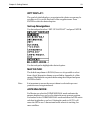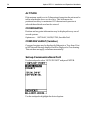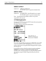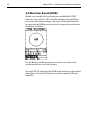
1
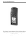
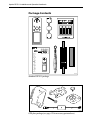
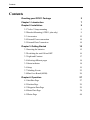
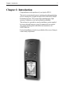
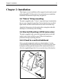
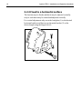
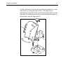
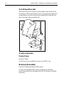
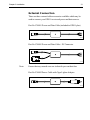
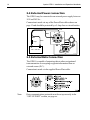
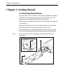
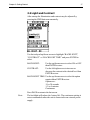
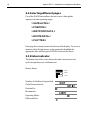
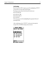
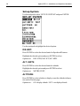
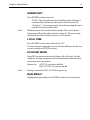
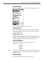
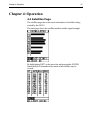
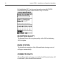
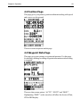
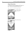
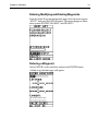
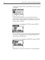
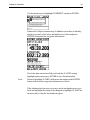
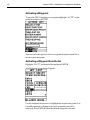
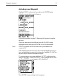
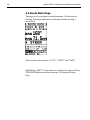
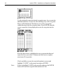
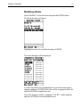
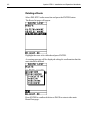
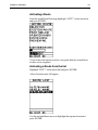
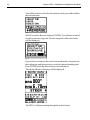
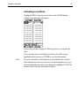
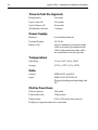
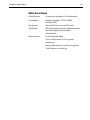
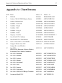
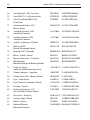
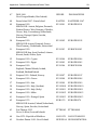
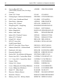
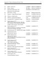
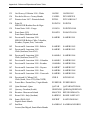
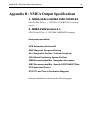
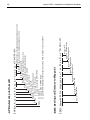
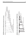
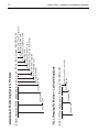
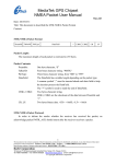
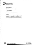
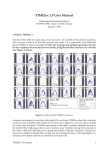
Distributed by
Any reference to Raytheon or
RTN in this manual should be
interpreted as Raymarine.
The names Raytheon and RTN
are owned by the
Raytheon Company.
Apelco GPS11 Installation and Operation Handbook
The technical and graphical information contained in this handbook, to the best of our knowledge, was
correct as it went to press. However, the Raytheon policy of continuous improvement and updating may
change product specifications without prior notice. Therefore, unavoidable differences between the
product and handbook may occur from time to time, for which liability
cannot be accepted by Raytheon.
Copyright Raytheon Marine Europe 1998
Apelco GPS11 Installation and Operation Handbook
Package Contents
Checking your GPS11 Package
The GPS11 package contains the following standard items:
1. Display unit with an internal antenna
2. Lanyard
3. Velcro fixing
4. Mounting bracket
(GPS11 plus only)
5. Power and Data connector
(GPS11 plus only)
6. Installation & Operation Guide
7. Warranty document
Items Missing?
If any of the above items are missing or damaged, please contact
your Apelco dealer or our Product Support Department to obtain
replacement parts. Please note that missing or damaged items
cannot be replaced without proof of purchase.
Registering this Product
Once you have checked that you have all of the listed components,
please take the time to complete the warranty document and return
it to your national distributor.
By returning this document you will receive prompt and expert
attention should you ever experience any difficulties with this
product. Also, your details are added to our customer database so
that you automatically receive new product brochures as and when
they are released.
Apelco GPS11 Installation and Operation Handbook
Package Contents
PWR
PAGE
MARK
ENTER
PWR
PAGE
MARK
ENTER
D4127-1
Standard GPS11 package
D4128-1
GPS plus package (see page 12 for accessory pat numbers)
Apelco GPS11 Installation and Operation Handbook
Contents
Contents
Checking your GPS11 Package
2
Chapter 1: Introduction
7
Chapter 2: Installation
9
2.1“Velcro” Strap mounting
9
2.2 Bracket Mounting ( GPS11 plus only)
9
2.3 Accessories
12
2.4 External Power connection
14
2.5 External Data Connection
14
Chapter 3: Getting Started
15
3.1 Inserting the batteries
15
3.2 Switching the unit ON and OFF
16
3.3 Light and Contrast
17
3.4 Selecting different pages
18
3.5 Status indicator
18
3.6 Setup
19
3.7 Marking Events
25
3.8 Man Over Board (MOB)
26
Chapter 4: Operation
27
4.1 Satellites Page
27
4.2 Position Page
29
4.3 Waypoint Data Page
29
4.4 Route Data Page
38
4.5 Plotter Page
48
Apelco GPS11 Installation and Operation Handbook
Chapter 5: Fault Finding & Maintenance
49
5.1 Fault Finding
49
5.2 How to Contact Apelco
49
5.3 Maintenance
52
Chapter 6: Specification
53
Appendix A : Chart Datums
57
Appendix B : NMEA Output Specifications
67
Chapter 1: Introduction
7
Chapter 1: Introduction
Congratulations on the purchase of your Apelco GPS11.
This unit is a navigational system consisting of a radio-positioning
receiver making use of signals from the NAVSTAR GPS (Global
Positioning System). The system offers simultaneously, high
accuracy, continuous cover and worldwide availability.
This unit may be operated as a purely standalone system supplied
by its own internal batteries or may be connected to an external
12v supply and integrated with further instumentation via a
NMEA data link.
For fixed installation a bracket is provided to allow secure fixing in
a wide variaty of positions.
Apelco GPS11 Installation and Operation Handbook
8
Important Information
All Raytheon equipment and accessories are designed to the highest standard
for use in the leisure marine environment.
Their design and manufacture conforms to the latest Electromagnetic
Compatibility (EMC) standards, but good installation is required to ensure that
performance is not compromised. Although every effort has been taken to
ensure that they will perform under all conditions, it is important to understand
what factors could affect the operation of the product. To avoid the risk of
EMC problems, all Raytheon equipment and cables connected to it should be;
❏
At least 1m (3 feet) from any equipment transmitting or cables carrying
radio signals e.g. VHF radios, cables and antennas. In the case of SSB
radios, the distance should be increased to 2m (7ft).
❏
At least 20m (66 feet) from large vessels equipped with radar.
❏
More than 2m (7 feet) from the direct path of a radar beam.
The following points should also be noted;
❏
Genuine Raytheon cables should be used at all times. Cutting and
rejoining these cables can compromise EMC performance and so should
be avoided unless doing so is detailed in the installation manual.
❏
Raytheon equipment should be serviced only by authorised Raytheon
service engineers. They will ensure that service procedures and replacement parts used will not affect EMC performance. There are no user
serviceable parts in any Raytheon product.
❏
Voltage drops below 10v in the power supply to our products can cause
the equipment to reset. This will not damage the equipment but will cause
the loss of some information and can change the operating mode. This
most frequently happens during engine starting, and so to reduce the risk
of this occurring, it is recommended that the equipment is supplied from a
different battery than the one used for engine start.
❏
Some products generate high voltages, and so never handle the cables/
connectors when power is being supplied to the equipment.
❏
Always check the installation before going to sea to make sure that it is not
affected by radio transmissions, engine starting etc.
❏
In some installations, it may not be possible to prevent the equipment from
being affected by external influences. In general this will not damage the
equipment but can lead to it resetting, or momentarily result in faulty
operation.
Please keep these notes for future reference.
Chapter 2: Installation
9
Chapter 2: Installation
This chapter covers installation of the support bracket and external
cable of the GPS11. If the unit is to be used purely as a standalone
handheld GPS then this chapter may be ignored.
2.1 “Velcro” Strap mounting
The unit is supplied with a “Velcro” strip which may be attached to
the rear case using the lanyard slots. Ensure that the strap is pulled
tight and the end tabs turned back and secured to the main strap.
Attach the fixing strip to the desired surface using glue or double
sided tape or sew the strip onto clothing.
2.2 Bracket Mounting ( GPS11 plus only)
The unit is supplied with a universal mounting bracket (selected
models only) which will allow your GPS to be slotted into a
permanent storage/operating position.
2.2.1 Fixed to a vertical bulkhead
Select your desired position and screw the backplate (1) to the
vertical bulkhead. Slot the main bracket (2) onto the top tab of the
backplate and then push the bottom of the main bracket back, to
allow the supplied finger bolt (3) to secure the base of the bracket.
D4117-1
10
Apelco GPS11 Installation and Operation Handbook
2.2.2 Fixed to a horizontal surface
The bracket may be fixed such that it may be adjusted vertically
only or such that it may be rotated and adjusted vertically.
For vertical adjustment only screw the backplate (1) to the desired
horizontal surface and then secure the main bracket (2) at the
desired angle using the finger bolt (3).
D4116-1
Chapter 2: Installation
11
To allow the bracket to be rotated assemble the backplate (1) to the
main bracket (2) using the finger bolt (3). The angle may be
adjusted later if required. Select your desired position and screw the
base plate (4) to the horizontal surface, then attach the backplate to
the baseplate using the finger bolt (5).
D4118-1
Apelco GPS11 Installation and Operation Handbook
12
2.2.3 Fixed to a rail
The bracket may be mounted to a rail using the same method as for
mounting to a horizontal surface but by reversing the base plate and
using stainless steel nuts and bolts (not supplied) to clamp the base
plate to the back plate around the rail.
D4119-1
2.3 Accessories
Carry Case
Part No. P36003
A soft carry case is available to protect your GPS11 unit.
Bracket Assembly
Part No. P36004 (included in GPS11 plus)
To allow the standard GPS11 unit to be bracket mounted the
bracket assembly that is included in the GPS11 plus kit is available
separately.
Chapter 2: Installation
13
External Connection
There are three external cable accessories available which may be
used to connect your GPS11 to external power and data sources.
Part No. P36001 Power and Data Cable (included in GPS11 plus)
D4124-1
Part No. P36005 Power and Data Cable + PC Connector
D4126-1
Note:
Ensure that any unused cores are isolated to prevent data loss
Part No. P36002 Power Cable with Cigar Lighter Adapter
D4125-1
Apelco GPS11 Installation and Operation Handbook
14
2.4 External Power connection
The GPS11 may be connected to an external power supply between
10V and 24V d.c..
Connection is made via any of the Power/Data cables shown on
page 13 and should be protected by a 5 Amp fuse or circuit breaker.
Red
4
Blue
5
3
6
Red
5 Amp
Blue
2
1
7
10V - 32V d.c.
D4121-1
2.5 External Data Connection
The GPS11 is capable of outputing data to other navigational
instrumentation or accepting waypoint information from an
external source (P.C.).
Connection is made via the supplied Power/Data cable.
Note:
Data communications protocols must be set up correctly in the
“SET-UP PORT” section, see page xx.
Chapter 3: Getting Started
15
Chapter 3: Getting Started
3.1 Inserting the batteries
Open the battery cover on the base of the unit by pulling the compartment latch (1) towards the side of the unit. The battery cover will
spring open revealing the black battery carrier within.
Remove the carrier and insert the four AA size batteries following the
+ and - marks.
Insert the loaded carrier back into the unit taking care to line up the
stud (2) on the carrier with the mark on the cover seal (3).
Close the battery cover and pull the latch toward the side of the unit.
The cover will click into position sealing the battery compartment.
Note:
The cover will not close if the battery carrier has been inserted
incorrectly.
D4120-1
Apelco GPS 11 Installation and Operation Handbook
16
3.2 Switching the unit ON and OFF
Press the PWR button to switch on your GPS11. The Startup screen
will be displayed for 5 seconds.
startup
After 5 seconds the GPS satellite information page will be displayed
showing the number and identification of the satellites being
received.
satstat
To switch off your GPS11 press and hold down the PWR button.
After a one second delay a countdown display will appear. Keep the
PWR button held down for a further three seconds until the display
switches off.
Chapter 3: Getting Started
17
3.3 Light and Contrast
After startup the illumination and contrast may be adjusted by
pressing the PWR button momentarily.
lgtcon
Use the trackpad up/down arrows to highlight “BACKLIGHT”,
“CONTRAST” or “BACKLIGHT TIME” and press ENTER to
select.
BACKLIGHT:
Use the up/down arrows to select ON or OFF
then ENTER to store.
CONTRAST:
Use the left/right arrows to increase or
decrease the contrast to the desired level then
ENTER to store.
BACKLIGHT TIME: Use the up/down arrows to select the option
required then ENTER to store.
Options are:
15 or 30 seconds
1, 2 or 4 minutes
Continuous
Press PAGE to return to the last screen.
Note:
The backlight will reduce the battery life. The continuous setting is
not recommended unless the unit is connected to an external power
supply.
Apelco GPS 11 Installation and Operation Handbook
18
3.4 Selecting different pages
Use of the PAGE button allows the unit to move through the
sequence of main operating pages:
> SATELLITES <
> POSITION <
> WAYPOINT DATA <
> ROUTE DATA <
> PLOTTER <
Each page has a menu bar near the bottom of the display. To access a
menu use the left/right arrows on the trackpad to highlight the
appropriate title and then press ENTER to activate the menu.
3.5 Status indicator
The bottom line of the screen shows the units current status and
cycles though three sets of information:
Battery Status:
Full
Half
Low
Number of Satellites being tracked:
Chart Datum selected:
Position Fix:
Illumination:
Operating Mode:
Differential Fix:
Chapter 3: Getting Started
19
3.6 Setup
Basic Setup of the GPS11 unit is accessed by highlighting SETUP?
on the menu bar on the SATELLITES page.
The Setup section is then divided into four sub-menus:
SET-UP SYSTEM
SET-UP PLOTTER
SET-UP NAVIGAT
SET-UP PORT
Sub menus are accessed by highlighting the appropriate line and
pressing ENTER.
After switching on select “SETUP?” on the menu bar using the
trackpad. Press ENTER to display the main menu.
Mainmen1
Apelco GPS 11 Installation and Operation Handbook
20
Set-up System
Use the trackpad to select “SET-UP SYSTEM” and press ENTER.
Setsys
Use the trackpad to highlight the desired option:
D/S UNIT:
Press ENTER to select the desired units for Speed and Distance.
Highlight the desired option and press ENTER to select.
Options are:
KM - KPH, NM - KT, MI - MPH.
ALT. UNITS:
Press ENTER to select the desired units for altitude.
Highlight the desired option and press ENTER to select.
Options are:
METRE, FEET,
ALTITUDE:
Press ENTER to select whether to display or not the altitude information on the Position page..
Options are:
ON -display altitude / OFF - not display altitude
Chapter 3: Getting Started
21
WARM START
Press ENTER to select a start area:
AUTO - The unit will search for all satellites and will initiate a
cold start if the unit has moved location while switched off.
“Selection” - A local area may be selected instructing the unit to
search for selected satellites first.
Note:
When the unit is first switched on the setting of the correct Warm
Start region will greatly reduce the time to first fix. The auto setting
could result in a time to first fix in excess of 30 minutes.
LOCAL TIME
Press ENTER to select a time offset from UTC.
Use the trackpad to input the correct local time difference for the area
you are in and press ENTER to select.
ECONOMY MODE
Stops GPS reception to increase the battery life of the unit. Use this
setting for entering waypoint and route information whilst the unit is
not being used for navigation.
Options are:
Note:
ACTIVE - reception disabled
NOT ACTIVE - reception enabled
Setting is returned to NOT ACTIVE on power up.
MAIN MENU?
Highlight this option and press ENTER to return to the main menu.
Apelco GPS 11 Installation and Operation Handbook
22
Set-up Plotter
Use the trackpad to select “SET-UP PLOTTER” and press ENTER.
Setplot
Use the trackpad to highlight the desired option:
CLEAR TRACK:
Press ENTER to clear the displays track. A confirmation page will
appear . Press ENTER once more to clear the stored track information from the memory.
RESET TRIP LOG:
Press ENTER to reset the displayed Trip Log. A confirmation page
will appear . Press ENTER once more to reset the trip log or use the
trackpad to highlight NO? and then press ENTER to cancel.
TRACK INTERVAL:
Press ENTER to select the time between track data saves.
Options are:
Note:
5 seconds
30 seconds
1 minute
2 minutes
5 minutes
The longer the time interval the larger is the track that can be stored
although the resolution of the final plot may be poor if the distances
travelled are small.
RANGE RINGS:
Press ENTER to switch the range rings ON or OFF.
Chapter 3: Getting Started
23
WPT DISPLAY:
The symbol which displays a waypoint on the plotter screen may be
set either to (O) or to the first letter of the waypoint name. Press
ENTER to select the desired option.
Set-up Navigation
Use the trackpad to select “SET-UP NAVIGAT” and press ENTER.
Setnav
Use the trackpad to highlight the desired option:
MAP DATUM:
The default map datum is WGS84, however it is possible to select
from a list of alternative datums as specified in Appendix A of this
manual. Highlight the required datum using the trackpad and press
ENTER to select.
Note:
It is important to ensure the correct datum is selected to prevent
position errors being introduced.
ANTENNA MODE:
For Marine use select the 2 DIMENSIONAL mode and enter the
antenna height above sea level to obtain the most accurate position.
For land use select 3 DIMENSIONAL mode and allow the GPS unit to
calculate height above sea level. Setting the mode to AUTO will
cause the GPS to use 3 dimensional mode when it is tracking 4 or
more satellites.
Apelco GPS 11 Installation and Operation Handbook
24
ALTITUDE
If the antenna mode is set to 2 dimensional operation the unit must be
told at what height above sea level it is. This will ensure the
positional accuracy is maintained. If 3 dimensional operation is
selected then altitude need not be entered.
COORDINATES
Position and waypoint information may be displayed in any one of
several systems.
Options are:
000000.00’, OSGB, UTM, Swedish Grid
COMPASS VARIAT (Variation)
Compass bearings may be displayed in Magnetic or True form. If set
to 0000 then all bearings displayed will be displayed as True bearing.
This unit does not apply variation automatically.
Set-up Communications Port
Use the trackpad to select “SET-UP PORT” and press ENTER.
Setport
Use the trackpad to highlight the desired option:
Chapter 3: Getting Started
25
SERIAL OUTPUT:
Options are:
NMEA182, NMEA183,
WAYPOINT (for PC waypoint communication)
SERIAL INPUT:
Options are:
DIFFERENTIAL (for differential receiver input),
WAYPOINT (for PC waypoint communication)
Note: Specifications of the NMEA sentences are given in
Appendix B of this manual.
3.7 Marking Events
Pressing the EVENT button on the GPS11 enters the current position
into the memory as a waypoint.
The display will show the position information.
Time and date of
EVENT automatically
entered as a comment
Event01
The event is automatically given the name ‘WPT XXX’ where XXX
is the next available number. Highlighting SAVE on the menu bar
will save the Event as a waypoint which will appear in the waypoint
list (see page 34).
It is possible to edit any of the Event data by using the trackpad to
highlight the relevant piece of information and pressing the
ENTER button. It is also possible to save the information as shown
and edit later using the Modify Waypoint facility described on
page 34).
Apelco GPS 11 Installation and Operation Handbook
26
3.8 Man Over Board (MOB)
Should a crewmember fall overboard press and hold the EVENT
button for 2 seconds. The GPS11 will immediately enter the Plotter
screen set to the minimum range. The range will automatically alter
to ensure that the MOB position and your current position remain on
the display at all times.
Mob
Use the Bearing and Range figures to steer the vessel back to the
original position to recover the casualty.
Pressing ENTER will cancel the MOB mode and return to the normal
plotter page. Use the PAGE button to continue using the GPS unit
normally.
Chapter 4: Operation
27
Chapter 4: Operation
4.1 Satellites Page
The satellites page shows the status and numbers of satellites being
tracked by the GPS11.
The main page shows the satellite numbers and the signal strength.
satel01
By highlighting DET? on the menu bar and pressing the ENTER
button details of azimuth and elevation of the satellites may be
viewed.
satel02
Apelco GPS11 Installation and Operation Handbook
28
By highlighting DIF? on the menu bar and pressing the ENTER
button details regarding a differential fix may be viewed.
difinfo
RECEPTION QUALITY
The bargraph shows the reception quality with a full bar indicating
100% reception
DGPS STATION
The identification number of the differential station being received
will appear automatically.
CORRECTED SATS
The satellites which are being corrected by the differential station will
be indicated by their identification numbers.
Chapter 4: Operation
29
4.2 Position Page
This page gives your primary position information along with speed
and course over the ground.
pos01
There are no menu options on this page.
4.3 Waypoint Data Page
This page gives your primary waypoint information. Use this page
for entering, deleting or editing waypoint information and activating
a waypoint.
wayp01
There are three menu options “ACTI?”, “EDIT?” and “DISP?”
Highlighting “DISP?” on the menu bar will allow the choice of Data,
CDI or BDI display.
Apelco GPS11 Installation and Operation Handbook
30
Waypoint Display Page
From the main waypoint page highlight the “DISP?” option and
press “ENTER” you will be presented with three options:
Data
Shows the main waypoint information page
CDI
Shows the Course Direction Indicator Page
Active waypoint
information
CDI01
BDI
BDI01
Shows the Bearing Direction Indicator Page
Chapter 4: Operation
31
Entering, Modifying and Deleting Waypoints
From the main Waypoint information page select the menu option
“EDIT?” and press the ENTER button. The menu changes to allow
three options ENTER?, MODIFY? and DELETE?
edit01
Entering a Waypoint
Select ENTER? on the menu bar and press the ENTER button.
A blank waypoint data page will appear.
editwp
Apelco GPS11 Installation and Operation Handbook
32
The highlighted setting is WPT:, press ENTER to select the waypoint
name option.
wptname
Use the trackpad up and down arrows to select the first letter or
number of your waypoint name then use the right arrow to move on
to the next digit. Continue until the waypoint name is complete (max.
6 digits) and press “ENTER”.
Use the down arrow to highlight LATITUDE: and press ENTER.
lat
Use the up and down arrows to select the digits and the right and left
arrows to move around until the correct waypoint latitude has been
entered. Press the ENTER button.
Use the down arrow to highlight LONGITUDE? and press ENTER.
lon
Repeat the above procedure to enter the correct waypoint longitude.
Chapter 4: Operation
33
Use the down arrow to highlight COMMENT: and press ENTER.
comment
If desired a 20 digit comment may be added to assist later in identifying the waypoint, select letters and numbers as before and press
ENTER to complete the waypoint information.
wptcompl
Check the data entered carefully and, with the VALID? setting
highlight on the menu press ENTER to save the information.
Note:
Failure to highlight VALID? in the menu bar and press the ENTER
button will cause the waypoint information to be lost.
If the information is incorrect you may use the trackpad arrows to go
back and highlight the setting to be changed or highlight CLEAR? on
the menu bar to clear the form and start again.
Apelco GPS11 Installation and Operation Handbook
34
Modifying a Waypoint
Select MODIFY? on the menu bar and press the ENTER button.
A list of stored waypoints will appear.
wptlst01
Use the trackpad down arrow to highlight the required waypoint.
Latitude, Longitude and comments will appear for each waypoint as
the list is advanced. Press ENTER when the desired waypoint is
located.
wptcompl
Use the trackpad to navigate around the screen and enter the modifications required. Highlight “VALID?” and press ENTER to store the
changes or highlight “ERASE?” and press ENTER to clear the
waypoint data and start again.
Chapter 4: Operation
35
Deleting a Waypoint
Select DELETE? on the menu bar and press the ENTER button.
A list of stored waypoints will appear.
wptlst01
Use the trackpad down arrow to highlight the required waypoint. Lat/
Lon and comments will appear for each waypoint as the list is
advanced. Press ENTER when the desired waypoint is located.
delwrn1
Press ENTER once more to confirm waypoint deletion or press
PAGE to return to the main Waypoint information page.
Note:
If the waypoint is used in a route then an error message will appear
giving the name of the route in which the waypoint is used. The route
must be edited to remove the waypoint before the waypoint can be
deleted from the waypoint list.
Apelco GPS11 Installation and Operation Handbook
36
Activating a Waypoint
To start the GPS11 tracking to a waypoint highlight “ACTI?” on the
menu bar and press ENTER.
actwpt01
You now have the option to select a waypoint from the stored list or
to enter a new waypoint.
Activating a Waypoint from the list
Highlight “LIST?” on the menu bar and press ENTER.
A list of stored waypoints will appear.
wptlst01
Use the trackpad down arrow to highlight the required waypoint. Lat/
Lon and comments will appear for each waypoint as the list is
advanced. Press ENTER when the desired waypoint is located.
Chapter 4: Operation
37
Activating a new Waypoint
Highlight NEW? on the menu bar and press the ENTER button.
A blank waypoint data page will appear.
editwp
Follow the procedure on page 31 Entering a Waypoint to complete
the form.
Check the data entered carefully and, with the VALID? setting
highlighted on the menu press ENTER to save the information..
Note:
The new waypoint will be stored in memory and added to the
waypoint list.
If the information is incorrect you may use the trackpad arrows to go
back and highlight the setting to be changed or highlight CLEAR? on
the menu bar to clear the form and start again
To stop tracking to a waypoint highlight “ACTI?” on the menu bar
and press ENTER. “DEACTIVATE?” will be highlight on the menu
bar. Press ENTER, a warning page will be displayed.
stopwarn
Press ENTER to stop tracking to that waypoint.
Apelco GPS11 Installation and Operation Handbook
38
4.4 Route Data Page
This page gives your primary route information. Use this page for
entering, deleting or editing route information and activating a
stored route.
route01
There are three menu options “ACTI?”, “EDIT?” and “DISP?”
Highlighting “DISP?” on the menu bar will allow the choice of Data,
CDI or BDI displays as indicated on page 30 Waypoint Display
Page.
Chapter 4: Operation
39
Editing a route
Highlight “EDIT?” from the menu bar and press ENTER.
Three options are given: “ENTER?”, “MODIFY?” and
“DELETE?”
Entering a Route
Select ENTER? on the menu bar and press the ENTER button.
A blank Route data page will appear.
edit02
The highlighted setting is RTE:, press ENTER to select the Route
number option.
rtename
Use the trackpad arrows to select the number (00 to 19) of the new
route and press “ENTER”. If the route number has already been used,
the previously entered route information will be displayed whereas if
the route is new the data sheet will be empty.
Use the down arrow to highlight the first waypoint line and press
ENTER.
Apelco GPS11 Installation and Operation Handbook
40
rtewpt01
Use the trackpad to enter the desired waypoint name. As you enter the
individual numbers or letters the first matching entry in the waypoint
library will be displayed. This allows you to select a waypoint
without having to enter the complete name. Press ENTER when the
correct waypoint is being displayed to enter the waypoint into the
route.
rtewp02
Press the down arrow to highlight the next waypoint data line and
repeat the above procedure. Continue until the route is complete
(maximum 20 waypoints).
Check carefully to ensure the route information is correct and
highlight “VALID?” on the menu bar and press ENTER.
Note:
Failure to highlight VALID? in the menu bar and press the ENTER
button will cause the waypoint information to be lost.
Chapter 4: Operation
41
Modifying a Route
Select MODIFY? on the menu bar and press the ENTER button.
The Route list page will appear.
rtelst
Highlight the route to be modified and press ENTER.
The route data page will be displayed.
modrte
Use the trackpad arrows to highlight the waypoint line that requires
changing and press ENTER. Select the correct waypoint from the list
and press ENTER to update the route.
Check the changes carefully , highlight “VALID?” on the menu bar
and press ENTER to store the modified route.
Apelco GPS11 Installation and Operation Handbook
42
Deleting a Route
Select DELETE? on the menu bar and press the ENTER button.
The Route list page will appear.
rtelst
Highlight the route to be deleted and press ENTER.
A warning message will be displayed asking for confirmation that the
route should be deleted.
rtedelcn
Press ENTER to confirm deletion or PAGE to return to the main
Route Data page.
Chapter 4: Operation
43
Activating a Route
From the main Route Data page highlight “ACTI?” on the menu bar
and press ENTER.
actrte01
You now have the option to select a waypoint from the stored list or
to enter a new waypoint.
Activating a Route from the list
Highlight “LIST?” on the menu bar and press ENTER.
A list of stored routes will appear.
rtelst1
Use the trackpad down arrow to highlight the required route and
press ENTER.
Apelco GPS11 Installation and Operation Handbook
44
You will be asked to select the direction in which you wish to follow
the selected route.
rtedir
Select Forward or Reverse and press ENTER. You will now be asked
to select your start waypoint. The first waypoint of the stored route
will be displayed.
rtestart
If you wish to commence the route from an alternative waypoint use
the trackpad up and down arrows to select the desired starting point.
Press ENTER when the desired start point is displayed.
The selected Route’s data page will be displayed.
rtedata1
The GPS11 will start tracking through the selected route.
Chapter 4: Operation
45
Activating a new Route
Highlight NEW? on the menu bar and press the ENTER button.
A blank route data page will appear.
Edit02
Follow the procedure on page 38 Entering a Route to complete the
form.
Check the data entered carefully and, with the VALID? setting
highlight on the menu press ENTER to save the information.
Note:
The new route will be stored in memory and added to the route list.
If the information is incorrect you may use the trackpad arrows to go
back and highlight the setting to be changed or highlight CLEAR? on
the menu bar to clear the form and start again.
Apelco GPS11 Installation and Operation Handbook
46
Advancing through a Route
When you reach a waypoint there are two options:
1. The GPS position will enter the arrival circle which is preset at 0.1nm
and will display the arrival message.
wptadv1
Press ENTER to display the Route Data for the next leg and start
tracking to the next waypoint.
2. You physically arrive at the waypoint but the GPS position is greater
than 0.1nm from the waypoint position (possibly due to poor
reception). In this case it will be necessary to manually advance to the
next waypoint as shown below.
From the Route Data page highlight ACTI? on the menubar and
press ENTER.
wptadv
Use the trackpad to highlight NEXT LEG? and press ENTER.
Chapter 4: Operation
47
After a short pause the arrival message will be displayed.
wptadv1
Press ENTER to display the Route Data for the next leg and start
tracking to the next waypoint.
Note:
The manual advance may be used at any stage if you wish to bypass a
waypoint and track to an alternative later in the Route.
De-activating a route
To stop tracking through a route highlight “ACTI?” on the menu bar
and press ENTER. Use the trackpad to highlight “STOP?” on the
menu bar and press ENTER, a warning page will be displayed.
stoptrack
Press ENTER to stop tracking through the route.
Apelco GPS11 Installation and Operation Handbook
48
4.5 Plotter Page
The plotter page gives a graphical display of the route history and
displays any waypoints that may be in view.
Plotter scale and trip
log reading
plot01
Menu options are ZOOM IN? or ZOOM OUT?
Highlight the appropriate instruction and press ENTER to change
the plotter scale. The range is from 0.02 to 250 of the units selected.
Note:
Plotter functions, including clearing the track memory can be
accessed via the SET-UP menu
Chapter 5: Fault Finding & Maintenance
49
Chapter 5: Fault Finding & Maintenance
5.1 Fault Finding
If your GPS11 fails to operate check the battery condition and ensure
that the contacts are clean. If an external power source is being used
check the voltage and ensure that the Power/Data plug is clean and
secure.
If the unit powers up but fails to obtain a fix ensure that the unit has a
clear view of the sky. Reception will be affected by buildings, trees
and other objects that restrict the signal from the satellites, it is wise to
check with another GPS operator locally to ensure that the satellite
system is fully operational
In the unlikely event that a fault develops within the unit there are no
user serviceable parts and the complete GPS11 should be returned to
a registered Apelco Service Agent for attention.
5.2 How to Contact Apelco
In the USA.
For technical Support
Please call 1-800-539-5539, extension 2445 or (603) 647-7530,
extension 2445. Our Fax number is 1-603-634-4756.
You may reach our Technical Service Department Monday through
Friday, 8:15 A.M. to 5:00 P.M. EasternStandard Time or Daylight
Saving Time. Our Technical Support Specialists are available to
answer questions about installing, operating, and troubleshooting
about your Apelco unit. You may also reach our Technical Support
Department via the Internet.
Questions may be addressed directly to:
[email protected]
Or, you may visit Apelco at the World Wide Web site for Raytheon
Electronics:
www.raymarine.com
50
Apelco GPS11 Installation and Operation Handbook
For accessories and parts
Please call 1-800-539-5539, extension 2120 or (603) 647-7530,
extension 2120.
Our Customer Service Department is available Monday through
Friday 8:15 A.M.to 5:00 P.M. Eastern Time. Please have the Apelco
part number ready when placing an order. (See the optional Accessory List in this manual on page 12.) If you are not sure which item
you need for your Apelco unit, please contact our Technical Support
Department before placing your order. Apelco accessory items and
parts are also available through your authorised Apelco dealer.
For product repair and service
When you first receive your unit, please be sure to complete and mail
the warranty card included in the package. In the unlikely event your
Apelco unit should develop a problem, please return the unit to our
Product Repair Centre. If you need service help, and you have not
mailed your warranty card, please include a copy of your original
purchase receipt to verify your warranty status.
Please return your unit to this address:
Apelco Product Repair Center
676 Island Pond Road
Manchester, NH. 03109-5420
Chapter 5: Fault Finding & Maintenance
51
In Europe
Contact your Apelco main distributor for assistance for the supply of
accessories and technical assistance. Faulty units may also be
returned to the distributor or returned directly to:
Raytheon Marine Europe Ltd.
Robinson Way
Anchorage Park
Portsmouth, PO3 5TD
England
The telephone number for Raytheon Marine Europe is (44) 1705
693611. The Fax number is (44) 1705 694642
Contact via the Internet:
Questions may be addressed directly to:
[email protected]
Or, you may visit Apelco at the World Wide Web site for Raytheon
Electronics:
www.raymarine.com.
52
Apelco GPS11 Installation and Operation Handbook
5.3 Maintenance
Chemical and abrasive materials must not be used to clean the
GPS11 housing; if it is dirty, clean it with a soft, damp cloth.
Examine all cables for chafing or damage to the outer shield and,
where necessary, replace with genuine Apelco cables and resecure.
Ensure that any external plugs and sockets are kept clean and dry.
Use small amounts of a silicon based grease to prevent corrosion on
exposed connectors.
Chapter 6: Specification
53
Chapter 6: Specification
Dimensions
Size:
51 x 150 x 33 mm
2.01” x 5.90” x 1.30”
Weight:
255g ( 9 oz.) with batteries
LCD Display:
100 x 64 FSTN with EL back light.
Receiver
Frequency:
1.575 GHz, C/A code.
Type:
8 genuine parallel channels with phase
tracking (predicts the next 4 in view).
Antenna:
Patch internal / integrated antenna
Maximum Speed:
2000km/hour
3 Dimensions:
Latitude, Longitude and Altitude; requires 4
or more satellates
Pos. Rate Update:
1 second
Automatic Selection of Satellites
Automatic Almanac update
Autolocalization
Accuracy
Horizontal Position: with SA code : 100m RMS (2D)
in RTCM 104 differential mode :
2 to 5 m RMS.
Velocity:
with SA code : 1.0km/hour RMS
in differential mode : 0.1 km/hour
Acceleration:
3g
Apelco GPS11 Installation and Operation Handbook
54
Time to First Fix (typical)
Reaquisition:
4 seconds
Up to 1 hour off:
30 seconds
Up to 24 hours off:
90 seconds
Worldwide cold start:
3 minutes
Power Supply
Batteries:
4 AA alkaline batteries
External Supply:
10-32v dc
Battery Life:
8 hrs in continuous permanent mode.
10 hrs in economy permanent mode.
16 hrs in discontiouous mode with a
use equivalent to one hour per day.
Temperature
Operating:
-100 to +600C (140 to 1400F)
Storage:
-200C to +700C (-40 to 1580F)
Data
Output:
NMEA0182, and 0183.
Input:
NMEA 0183, RTCM 104.
Waypoint loading and unloading with
P.C.
Plotter Functions
Plotter Capacity:
300 points
Plotter time scale:
25 hours max.
Plotter scales:
0.02 to 250 in the units selected
Display of waypoints and active route plan.
Chapter 6: Specification
55
Main Functions
Chart Datums:
As shown in Appendix A of this manual.
Coordinates:
latitude, longitude, UTM, OSGB,
Swedish Grid
Speed and Course over the Ground.
Navigation:
Waypoints:
600 waypoints each with 6 alphanumerical
character display and automatic
classification.
Other features:
Event mark including
20 reversible routes of 20 wayponts
maximum.
Range and bearing to a selected waypoint.
Total distance covered log.
56
Apelco GPS11 Installation and Operation Handbook
Appendix A : Reference Ellipsoids and Datum Table
57
Appendix A : Chart Datums
Code Name
Abbrev’ 11
Abbrev’ 23
0
WGS 84
WGS84
WGS84DEFAULT
1
Adinan - MEAN FOR Ethiopia, Sudan
ADINES
ADINANMEANS
2
Adinan - Burkina Faso
ADINBUR
ADINANBURKIN
3
Adindan - Cameroon
ADINCAM ADINANCAMER
4
Adindan - Etiopia
ADINETH
5
Adindan - Mali
ADINMAL ADINANMALI
6
Adindan - Senegal
ADINSEN
ADINANSENEG
7
Adindan - Sudan
ADINSUD
ADINANSUDAN
8
Afgooye - Somalia
AFGOSOM AFGOOVESOMALI
9
Ain el Abd 1970 - Bahrain
AINBAH
AIN1970BAHR
10
Ain el Abd 1970 - Saudi Arabia
AINSAUD
AIN1970SAUDI
11
Anna 1 Astro 1965 - Cocos Islands
ANNCOCO ANNA1COCOSIS
12
Antiguaa Island Astro 1943
Antigua (Leeward Islands)
ANT1943
ANTIGUAIS1943
13
Arc 1950
MEAN FOR Botswana, Lethoso, Malawi,
Swaziland, Zaire, Zambia, Zimbabwe
ARC1950
ARC1950MEAN
14
Arc 1950 - Botswana
ARC9501
ARC1950BOTSWA
15
Arc 1950 - Burundi
ARC9502
ARC1950BURUND
16
Arc 1950 - Lethoso
ARC9503
ARC1950LETHOS
17
Arc 1950 - Malawi
ARC9504
ARC1950MALAWI
18
Arc 1950 - Swaziland
ARC9505
ARC1950SWAZIL
19
Arc 1950 - Zaire
ARC9506
ARC1950ZAIRE
20
Arc 1950 - Zambia
ARC9507
ARC1950ZAMBIA
21
Arc 1950 - Zimbabwe
ARC9508
ARC1950ZIMBAB
22
Arc 1960 - MEAN FOR Kenya, Tanzania
ARC1960
ARC1960MEAN
23
Ascension Island 1958
ASC1958
ASCENSIS1958
ADINANETHIOP
Apelco GPS11 Installation and Operation Handbook
58
24
Astro Beacon E 1945 - Iwo Jima
IWOJIMA
ASTROIWOJIMQA
25
Astro DOS 71/4 - St. Helena Island
STHELEN
ASTROSTHELISL
26
Astro Tern Island (FRIG) 1961
Tern Island
TERNISL
ASTROTERN1961
27
Astranomical Station 1952
Marcus Island
MARCUIS
ASTO1952MARIS
28
Australian Geodetic 1966
Autralia & Tasmania
AUSTR66
AUSTRALAIN1966
29
Autralian Geodetic 1984
Autralia & Tasmania
AUSTR84
AUSTRALIAN1984
30
Ayabelle Lighthouse - Djibouti
DJIBOUT
AYABELLEDJIBO
31
Bellevue (IGN)
Efate & Erromango Islands
BELLVUE BELLEVEFATE
32
Bermuda 1957 - Bermuda
BERMUDA BERMUDA1957
33
Bissau - Guniea - Bissau
BISSAU
BISSAUGUINEA
34
Bogota Observatory - Colombia
BOGOTA
BOGOTACOLOMBI
35
Bukit Rimpah
Indonesia (Bangka & Belitung Islands
BUKITRI
BUKITRIMPAH
36
Camp Area Astro
Antarctica (McMurdo Camp Area)
ANTARCT CAMANTARCTICA
37
Campo Inchauspe - Argentina
ARGENTI
CAMPARGENTIA
38
Canton Astro 1966 - Phoenix Islands
PHEONIX
CANTON66
39
Cape - South Africa
SAFRICA
CAPESAFRICA
40
Cape Canaveral - Bahamas, Florida
CANAVEL CAPEBAHAMFLO
41
Carthage - Tunisia
TUNISIA
CARTHAGETUNIS
42
Chaham Island Astro 1971
New Zealand (Chatham Island)
CHATHIS
CHATHAMIS1971
43
Chua Astro - Paraguay
PARAGUY CHUAPARAGUAY
44
Corrego Alegre - Brazil
BRAZIL
CORREGOBRAZIL
45
Dabola - Guinea
GUINEA
DABOLAGUNEA
46
Djakarta (Batavia)
Indonesia (Sumatra)
DJAKARTA DJAKARTAINDON
Appendix A : Reference Ellipsoids and Datum Table
59
47
DOS 1968
New Georgia Islands (Gizo Islands)
GIZOISL
DOS1968GIZOIS
48
Easter Island 1967 - Easter Island
EASTISL
EASTERISL1967
49
European 1950
MEAN FOR Austria, Belgium, Denmark,
Finland, France, West Germany, Gibralter,
Greece, Italy, Luxembourg, Netherlands,
Norway, Portugal, Spain, Sweden,
Switzerland
EU19501
EUROPE19501
50
European 1950
MEAN FOR Austria, Denmark, France,
West Germany, Netherlands, Switzerland
EU19502
EUROPE19502
51
European 1950
MEAN FOR Iraq, Isreal, Jordan, Lebanon,
Kuwait, Saudi, Arabia, Syria.
EU19503
EUROPE19503
52
European 1950 - Cyprus
EU19504
EUROPE19504
53
European 1950 - Egypt
EU19505
EUROPE19505
54
European 1950
EU19506
EUROPE19506
England, Channel Islands, Ireland,
Scotland, Shetland Islands
55
Eropean 1950 - Finland, Norway
EU19507
EUROPE19507
56
European 1950 - Greece
EU19508
EUROPE19508
57
European 1950 - Iran
EU19509
EUROPE19509
58
European 1950 - Italy (Sardinia)
EU195010 EUROPE195010
59
European 1950 - Italy (Sicily)
EU195011 EUROPE195011
60
European 1950 - Malta
EU195012 EUROPE195012
61
European 1950 - Portugal, Spain
EU195013 EUROPE195013
62
European 1979
EUR1979
EUROPE1979
MEAN FOR Austria, Finland, Netherlands,
Norway, Spain, Sweden, Switzerland
63
Fort Thomas 1955
Nevis, St. Kitts (Leeward Islands)
FTTHOM
FTTHOMAS
64
Gan 1970 - Republic of Maldives
GAN1970
GAN1970MALDI
65
Geodetic Datum 1949 - New Zealand
NEWZEAL GEOD49NEWZEAL
Apelco GPS11 Installation and Operation Handbook
60
66
Graciosa Base SW 1948
Azores (Faial, Graciosa, Pico, Sao Jorge,
Terciera)
AZORES
GRACIOSAZORES
67
Guam 1963 - Guam
GUAM
GUAM1963
68
Gunung Segara - Indonesia (Kalimantan)
INDONES GUNUNGSEGARA
69
GUX 1 Astro - Guadalcanal Island
GUADISL GUX1ASTRO
70
Herat North - Afganistan
AFGHAN
71
Hjorsey 1955 - Iceland
ICELAND HJORSEY1955
72
Hong Kong 1963 - Hong Kong
HONGKNG HONGKONG1963
73
Hu-Tzu-Shan - Taiwan
TAIWAN
74
Indian - Bangladesh
BANGLAD INDIANBANGLAD
75
Indian - India, Nepal
NEPAL
INDIANINDIANEP
76
Indian 1954 - Thailand, Vietnam
54THAIL
INDIAN1975THA
77
Indian 1975 - Thailand
75THAIL
INDIAN1975THA
78
Ireland 1965 - Ireland
IRELAND IRELAND1965
79
ISTS 073 Astro 1968
South Georgia Islands
SGEORGA ISTS061AS1968S
80
ISTS 073 Astro 1969 - Diego Garcia
DIEGOGA ISTS073AS1969
81
Johnston Island 1961 - Johnston Island
JOHNSTN JOHNSTON1961
82
Kandawala - Sri Lanka
SRILANK KANDAWALASRIL
83
Kerguelen Island 1949
KERGUIS KERGUELEN1949
84
Kertau 1948 - West Malaysia & Singapore
WESTMAL KERTAU1948
85
Kusaie Astro 1961 - Cayman Brac Island
CAYBRAC KUSAIEAST1951
86
L. C. 5 Astro 1961 - Cayman Brac Island
CAYBRAC LC5ASTRO1961
87
Leigon - Ghana
GHANA
LEIGONGHANA
88
Liberia 1964 - Liberia
LIBERIA
LIBERIA1964
89
Luzon - Philippines (Excluding Mindanao)
LUZON1
LUZONPHILIPP1
90
Luzon - Philippines (Mindanao)
LUZON2
LUZONPHILLIPP2
91
Maha 1971 - Mahe Island
MAHAISL MAHA1971
92
Massawa - Ethio[ia (Eritrea)
ETHIOPI
93
Merchich - Morocco
MOROCCO MERCHICHMOROC
94
Midway Astro 1961 - Midway Islands
MIDWYIS MIDWAYAS1961
HERATNORTH
HUTZUSHAN
MASSAWAETHIOP
Appendix A : Reference Ellipsoids and Datum Table
61
95
Minna - Cameroon
CAMERN MINNACAMEROON
96
Minna - Nigeria
NIGERIA
97
Montserrat Island Astro 1958
Montserrat (Leeward Islands)
MONSERT MONTSERIS1958
98
M’Poraloko - Gabon
GABON
MPORALOKOGAB
99
Nahrwan - Oman (Masirah Island)
OMAN
NAHRWANOMAN1
100
Nahrwan - Saudi Arabia
SAUDIAR NAHRWANSAUDI2
101
Nahrwan - United Arab Emirates
UAE
NAHRWANUEA3
102
Naparima BWI - Trinidad & Tobago
TR&TOB
NAPARIMABWI
103
North American 1927
MEAN FOR Antigua, Barbados, Barbuda,
Caicos Islands, Cuba, Dominican Republic,
Grand Cayman, Jamaica, Turks Islands
NAMER1
NAMER19271
104
North American 1927
NAMER2
MEAN FOR Belize, Costa Rica, El Salvador,
Guatemala, Honduras, Nicaragua
NAMER19272
105
North American 1927 - MEAN FOR Canada NAMER3
NAMER19273
106
North American 1927
MEAN FOR CONUS
NAMER4
NAMER19274
107
North American 1927
NAMER5
MEAN FOR CONUS
(East Mississippi River) including Louisiana,
Missouri, Minesota
NAMER19275
108
North American 1927
MEAN FOR CONUS
(West of Mississippi River)
North American 1927 - Alaska
NAMER6
NAMER19276
NAMER7
NAMER19277
109
MINNACAMEROON
110
North Amerian 1927
Bahamas (Acdept San Salvador Island)
NAMER8
NAMER19278
111
North American 1927
Bahamas (San Salvador Island)
NAMIR9
NAMER19279
112
North American 1927
Canada (Alberta, British Columbia)
NAMIR10 NAMER192710
113
North Ameria 1927
Canada (Manitoba, Ontario)
NAMIR11 NAMER192711
Apelco GPS11 Installation and Operation Handbook
62
114
North America 1927
Canada (New Brunswick, Newfoundland,
Nova Scotia, Quebec)
NAMER12 NAMER192712
115
North America 1927
NAMER13 NAMER192713
Canada (Northwest Territories, Saskatchewan)
116
North America 1927 - Canada (Yukon)
NAMER14 NAMER192714
117
North American 1927 - Canal Zone
NAMER15 NAMER192715
118
North American 1927 - Cuba
NAMER16 NAMER192716
119
North American 1927
Greenland (Hayes Peninsula)
NAMER17 NAMER192717
120
North American 1927 - Mexico
NAMER18 NAMER192718
121
North American 1983
Alaska, Canada, CONUS
NAMER19 NAMER192719
122
North American 1983
Central America, Mexico
NAMER20 NAMER192720
123
Observatorio Metereo 1939
Azores (Corvo & Flores Islands)
AZORES
OBSERVMET1939
124
Old Egyptian 1907 - Egypt
EGYPT
OLDEGYPT1907
125
Old Hawaiian
MEAN FOR Hawaii, Kauai, Maui, Oahu
OHAWN1 OLDHAWN1
126
Old Hawaiian - Hawaii
OHAWN2 OLDHAWN2
127
Old Hawaiian - Kauai
OHAWN3 OLDHAWN3
128
Old Hawaiian - Maui
OHAWN4 OLDHAWN4
129
Old Hawaiian - Oahu
OHAWN5 OLDHAWN5
130
Oman - Oman
OMAN
OMAN
131
Ord. Survey G. Britain 1936
MEAN FOR England, Isle of Man,
Scotland, Shetland Islands, Wales
OSGB1
OSGB19361
132
Ord. Survey G. Britain 1936 - England
OSGB2
OSGB19362
133
Ord. Survey G. Britain 1936
England, Isle of Man, Wales
OSGB3
OSGB19363
134
Ord. Survey G. Britain 1936
Scotland, Shetland Islands
OSGB4
OSGB19364
Appendix A : Reference Ellipsoids and Datum Table
63
135
Ord. Survey G. Britain 1936 - Wales
OSGB5
OSGB19365
136
Pico de las Nieves - Canary Islands
CANISL
PICONIEVES
137
Pitcairn Astro 1967 - Pitcairn Islands
PITISL
PITCAIRN1967
138
Point 58
MEAN FOR Burkina Faso & Niger
POINT58
POINT58
139
Pointe Noire 1948 - Congo
CONGO
POINTEN1948
140
Porto Santo 1936
Porto Santo, Madeira Islands
PSANTO
POSANTO1936
141
Provisonal S. American 1956
MEAN FOR Bolivia, Chile, Colombia,
Ecuador, Guyana, Peru, Venezuela
SAMER1
SAMER19561
142
Provisonal S. American 1956 - Bolivia
SAMER2
SAMER19562
143
Provisonal S. American 1956
Chile (Southern, Near 430S)
SAMER3
SAMER19563
144
Provisonal S. American 1956
Chile (Southern, Near 430S)
SAMAR4
SAMER19564
145
Provisonal S. American 1956 - Columbia
SAMAR5
SAMER19565
146
Provisonal S. American 1956 - Ecuador
SAMAR6
SAMER19566
147
Provisonal S. American 1956 - Guyana
SAMER7
SAMER19567
148
Provisonal S. American 1956 - Peru
SAMER8
SAMER19568
149
Provisonal S. American 1956 - Venezuela
SAMER9
SAMER19569
150
Provisional S. Chilean 1963
Chile (South , Near 530S) (Hito XVIII)
CHILE
SCHILE1963
151
Puerto Rico - Puerto Rico, Virgin Islands
PUERTOR PUERTORICO
152
Qatar National - Qatar
QATAR
153
Qornoq - Greenlan (South)
GREENDS QORNOQGREENLD
154
Reunion - Mascarene Islands
MASCISL REUNIONMASCA
155
Rome 1940 - Italy (Sardinia)
SARDINI
ROME 1940ITALY
156
Santo (DOS) 1965
Espirito Santo Islands
ESPIRIT
SANTODOS1965
157
Sau Braz
Azores (Sao Miguel, Santa Maria Islands
SAOBRAZ SAOBRAZAZORES
QATARNATIONAL
Apelco GPS11 Installation and Operation Handbook
64
158
Sapper Hill 1943 - East Falkland Islands
EFALKLD SAPPERHILL43
159
Schwareck - Namibia
NAMIBIA
SCHWARZECK
160
Selvagem Grande - Salvage Islands
SALVAGI
SELVAGEMGRAND
161
SGS 85 - Soviet Geodetic System 1985
SGS85
SGS85SOVIET85
162
South American 1969
SAMER10 SAMER196910
MEAN FOR Argentina, Bolivia, Brazil,
Chile, Colombia, Ecuador, Guyana, Paraguay,
Peru, Trinidad & Tobago, Venezuela
163
South American 1969 - Argentina
SAMER11 SAMER196911
164
South American 1969 - Bolivia
SAMER12 SAMER196912
165
South American 1969 - Brazil
SAMER13 SAMER196913
166
South American 1969 - Chile
SAMER14 SAMER196914
167
South American 1969 - Colombia
SAMER15 SAMER196915
168
South American 1969 - Equador
SAMER16 SAMER196916
169
South American 1969
Ecuador (Baltra, Galapagos)
SAMER17 SAMER196917
170
South American 1969 - Guyana
SAMER18 SAMER196918
171
South American 1969 - Paraguay
SAMER19 SAMER196919
172
South American 1969 - Peru
SAMER20 SAMER196920
173
South American 1969 - Trinidad & Tobago
SAMER21 SAMER196921
174
South American 1969 - Venezuala
SAMER22 SAMER196922
175
South Asia - Singapore
SINGAPR
SOUTHASIASING
176
Tananarive Observatory 1925
Madagascar
MADAG
TANANARIV1925
177
Timbalai 1948
Brunei, East MAlaysia (Sabah, Sarawak)
BRUNEI
TIMBALI1948
178
Tokyo - MEAN FOR Japan, Korea, Okinawa TOKYO1
TOKYO1
179
Tokyo - Japan
TOKYO2
TOKYO2
180
Tokyo - Korea
TOKYO3
TOKYO3
181
Tokyo - Okinawa
TOKYO4
TOKYO4
182
Tristan Astro 1968 - Tristan da Cunha
TRISTAN
TRISTANAST1968
183
Viti Levu 1916 - Fiji (Viti Levu Island)
VITLEVU VITILEVU1916
Appendix A : Reference Ellipsoids and Datum Table
65
184
Wake-Eniwetok 1960 - Marchall Islands
WAKEENI WAKEENIWE1960
185
Wake Island Astro 1952- Wake Atoll
WAKEATO WAKEASTRO1952
186
WGS 1972 - Global Definition
WGS1972
WGS1972
187
Yacare - Uruguay
YACARE
YACARE
188
Zanderij - Suriname
ZANDERI
ZANDERIJ
66
Apelco GPS11 Installation and Operation Handbook
Appendix B : Data Output/Input Specifications
Appendix B : NMEA Output Specifications
1 - NMEA 0182 or NMEA 0180 COMPLEX
8 DATA bits, D7 bit = 1, 1 STOP bit, 1200 BAUD, even parity,
rate 4 s.
2 - NMEA 0183 Version 2.1
8 DATA bits,D7 bit = 0, 1 STOP bit, 4800 BAUD, no parity
Sentences transmitted:
-APB Automatic pilot format B
-BWC Waypoint, Range and bearing
-GLL Geographic Position - Latitude/Longitude
-GGA Global Positioning System Fix Data
-RMB Recommended Min. Navigation Information
-RMC Recommended Min. Specific GPS/TRANSIT Data
-VTG Speed and Course
-ZTG UTC and Time to Destination Waypoint
Sentence information is shown on the following pages.
67
Waypoint ID
Distance, nautical miles
Bearing, degrees magnetic
Bearing, degrees true
Waypoint longitude, E/W
Waypoint latitude, N/S
UTC of observation
$BWC, hhmmss,llll.lll, a, yyyyy.yyy, a, x.x, T, x.x, M, x.x, N, c--c *hh<CR><LF>
-BWC Bearing and Distance to Waypoint
Heading to steer to destination waypoint magnetic or true
Bearing, Present position to destination magnetic or true
Destination waypoint ID
Bearing origin to waypoint magnetic or true
Status: A = perpendicular passed at waypoint
Status: A = arrival circle entered
XTE units, nautical miles
Direction to steer L/R
Magnitude of XTE (cross track error)
Status: A = Data valid or not used,
V = Loran-C cycle lock warning flag
Status: A = Data Valid
V = Loran-C blink or SNR warning
V = General warning flag for other navigation systems when a reliable fix is not available
$APB, A, A, x.x, a, N, A, A, x.x, a, c--c, x.x, a, x.x, a *hh<CR><LF>
-APB Automatic pilot format B
68
Apelco GPS11 Installation and Operation Handbook
Latitude, N/S
Status: A = valid data, V = Navigation receiver warning
UTC of position
Magnetic variation, E/W
Date: dd|mm|yy
Course over ground, degrees true
Speed over ground, knots
Longitude, E/W
$RMC, hhmmss, A, llll.lll, a, yyyyy.yyy, a, x.x, x.x, xxxxxx, x.x, a *hh<CR><LF>
-RMC Recommended Minimum Specific GPS?TRANSIT Data
Arrivial Status: A = arrival circle entered
or perpendicular passed
V = not entered / passed
Destination closing velocity, knots
Bearing to destination, degrees true
Range to destination waypoint, nautical miles
Destination waypoint longitude, E/W
Destination waypoint latitude, N/S
Destination waypoint ID
Origin waypoint ID
Direction to steer, L/R
Cross track error, nautical miles
Data status: A = Data valid, V = Navigation receiver warning
$RMB, A, x.x, a, c--c, c--c, llll.lll, a, yyyyy.yyy, a, x.x, x.x, x.x, A *hh<CR><LF>
-RMB Recommended Minimum Navigation Information
Appendix B : Data Output/Input Specifications
69
Latitude, N/S
Status: A= valid, V = not valid
UTC of position
Longitude, E/W
$GLL, llll.lll, a, yyyyy.yyy, a, hhmmss, A *hh<CR><LF>
-GLL Geographic Position - Latitude/Lingitude
Latitude, N/S
UTC of position
Differential reference station ID
Age of Differential GPS data
Units of geoidal separation, meters
Geoidal separation
Units of antenna altitude, meters
Antenna altitude re: mean-sea level (geoid)
Horizontal dilution of position
Number of satellaties in use
GPS quality indicator
Longitude, E/W
$GGA, hhmmss,llll.lll,a, yyyyy.yyy, a, x, xx, x.x, x.x, M, x.x, M, x.x, xxxx *hh<CR><LF>
-GGA Global Positioning System Fix Data
70
Apelco GPS11 Installation and Operation Handbook
Destination waypoint ID
Time to go, hh = 00 to 99
UTC of observation
$ZTG, hhmmss, hhmmss, c--c *hh<CR><LF>
-ZTG UTC and Time to Destination Waypoint
Speed over ground, km/hr
Speed over ground, knots
Course, degrees magnetic
Course, degrees true
$VTG, x.x, T, x.x,M, x.x, N, x.x, K *hh<CR><LF>
-VTG Speed and Course
Appendix B : Data Output/Input Specifications
71
72
Apelco GPS11 Installation and Operation Handbook
Document Number: 81145-1
Raytheon Marine Company
676 Island Pond Road
Manchester, NH 03109-5420 USA
TEL (603) 647-7530
FAX (603) 634-4756
http://www.raytheon.com
Raytheon Marine Europe Ltd.
Anchorage Park, Portsmouth
Hampshire, PO3 5TD England
TEL +44 (0) 1705 693611
FAX +44 (0) 1705 694642
Printed in France