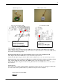
1
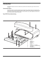
SmartPilot S1 Wheel & Tiller
Service Manual
D10048_1
Document number 83186-1
January 2007
SeaTalk® is a Registered Trademark of Raymarine
SeaStar® is a Registered Trademark of Teleflex Incorporated
BayStar is a Trademark of Teleflex Incorporated
NMEA® is a Registered Trademark of the National Marine Electronics Association
All other trademarks used in this document are acknowledged.
© Copyright Raymarine UK Ltd 2005.
Contents
Important Information ...........................................................................................3
Safety notices .............................................................................................................. 3
CE marking of equipment/replacement parts .............................................................. 3
EMC conformance ....................................................................................................... 3
Waste Electrical and Electronic (WEEE) Directive ...................................................... 3
Technical accuracy ...................................................................................................... 3
Warranty ...................................................................................................................... 3
Introduction ...........................................................................................................4
General description...................................................................................................... 4
Type S0/S1G assembly drawing ................................................................................. 4
Spares .....................................................................................................................5
Functional tests .....................................................................................................6
Introduction .................................................................................................................. 6
Equipment and tools .................................................................................................... 6
Initial inspection checks ............................................................................................... 6
Rate gyro connection................................................................................................... 6
Detailed diagnosis ....................................................................................................... 6
Step 1 - Power checks................................................................................................. 6
Step 2 - System checks ............................................................................................... 7
Step 3 - Rate gyro........................................................................................................ 7
Step 4 - Compass ........................................................................................................ 7
Step 5 - Rudder Reference (Not applicable for Verado & Tiller Pilots)........................ 8
Step 6 - Clutch - Auto (Not applicable to S1 Tiller & Wheel) ....................................... 8
Step 7 - Clutch - Standby (Not applicable to S1 Tiller & Wheel).................................. 8
Step 8- H-Bridge .......................................................................................................... 8
Step 9 - NMEA............................................................................................................. 8
Step 10 - EEPROM Test.............................................................................................. 8
Disassembly and reassembly ..............................................................................9
Tools required.............................................................................................................. 9
Disassembly/reassembly ............................................................................................. 9
Software ...............................................................................................................10
Software history ......................................................................................................... 10
Software upgrade ...................................................................................................... 10
Product history ....................................................................................................12
Technical updates...................................................................................................... 12
Diagrams ..............................................................................................................25
Parts list S1 &S1G ..................................................................................................... 36
Parts list S0 & S0G Tiller & Wheel............................................................................. 40
2
3
Important Information
Safety notices
CAUTION:
Electrostatic discharge
The S1(G) course computer contains electrostatic sensitive components. Always observe the appropriate
precautions when handling, shipping and storing this product. Failure to do so could result in permanent
damage to the equipment.
CE marking of equipment/replacement parts
If the Raymarine equipment under repair, test, calibration, installation or setting to work carries the European CE
mark, only parts and components supplied or approved for such use by Raymarine should be used in order to
maintain compliance with the relevant CE requirements.
Incorporation, use or attachment, by any means, of parts or components not supplied or not approved for such
use by Raymarine or, if supplied or approved for use by Raymarine, not properly fitted in accordance with
instructions published, provided or recommended by Raymarine, may cause the equipment to malfunction and in
particular, to become unsafe or to no longer meet the relevant CE requirements. In these circumstances,
Raymarine excludes liability to the fullest extent permissible in law for any loss or damage including any liability for
its contribution to such loss or damage by its negligent acts or omissions.
EMC conformance
All Raymarine equipment and accessories are designed to the best industry standards for use in the recreational
marine environment.
The design and manufacture of Raymarine equipment and accessories conform to the appropriate
Electromagnetic Compatibility (EMC) standards, but correct installation is required to ensure that performance is
not compromised.
Waste Electrical and Electronic (WEEE) Directive
The WEEE Directive requires the recycling of waste electrical and electronic equipment. Whilst the WEEE
Directive does not apply to some of Raymarine’s products, we support its requirements as par t of our
environmental policy and we ask you to be aware of how you should dispose of this product. The crossed out
wheelie bin symbol found on our products signifies that it should not be disposed of in general waste or landfill.
Please contact your local dealer, national distributor or Raymarine Technical Services for information on product
disposal.
Technical accuracy
The technical information contained within this Service Manual, to the best of our knowledge, was correct at the
time of writing. However, Raymarine cannot accept liability for any inaccuracies or omissions it may contain.
In addition Raymarine’s policy of continuous product improvement may change specifications without notice. As a
result Raymarine cannot accept any liability for any differences between the product and the manual.
Warranty
This unit contains no serviceable parts, if the unit has failed replace PCB or rate gyro as necessary.
4
Introduction
This manual describes the service and maintenance procedures for the Raymarine type S1 and S1G Course
Computer.
General description
The Course Computer processes information from the sensors in the autopilot system so it can steer the boat
using the drive unit. The Course Computer assembly consists of a plastic case, a printed circuit board (PCB). The
PCB carries a microprocessor, electronic circuitry to control the drive unit, a power amplifier for the drive motor
and a connector block for all inputs and outputs.
Type S0/S1G assembly drawing
3
4
2
1
6
5/5a
Description
Rate giro (Kionix)
Ring ferrite
Connector cover
Housing
Fuse (Power in) - 15 A (S1/S1G)
Fuse (Power in) - 10 A (S1 Tiller & Wheel)
PCB assembly
Fuse (SeaTalk) - 2 A
D8595-1
7
Item
1.
2.
3.
4.
5.
5a
6.
7.
5
Spares
Item
Spare /Accessory
3
4
Connector cover
Housing
5
5a
7
Fuse 15 A (S1 & S1G)
Fuse 10A (S0 Tiller & Wheel)
Fuse 2 A
6
PCB
1
Gyro
Part Number
Comments
less gyro
A18069
Kionix - from Aug. 2005 (Revision E PCBs)
6
Functional tests
Introduction
This section describes how to complete basic functional tests on the Course Computer aiding fault diagnosis.
Equipment and tools
•
•
•
•
•
•
•
•
ST6001/2 Control Head
Rudder Reference (Not applicable to Verado or Tiller pilot versions)
Fluxgate Compass
C/E Series unit
DVM (Digital Volt Meter)
12V dc 10A PSU (Power Supply Unit)
Type 1 pump
A conventional 330 Ohm resistor, rated at 1 Watt
Initial inspection checks
Before applying power to the Course Computer carry out following visual inspections:
1. Remove the connector cover, the PCB retaining screw and slide the PCB out of the case.
1. Check that the two fuses, F1 (15A), F2 (2A) are the correct rating and not blown.
2. Visually inspect the PCB for any obvious signs of component damage or blackening, paying particular attention to the FETs and main power components.
3. Check that capacitor C43 polarity is correct (see Tech Update TU228)
4. Check that resistance value of R18 matches the requirement of the gyro fitted (see Tech Update 332)
Rate gyro connection
The plug is designed to fit one way into the socket. Check the plug is correctly inserted and fully seated.
Detailed diagnosis
Before starting testing ensure that the following are connected to the Course Computer:
•
•
•
•
•
Fluxgate compass
Rudder reference (Not applicable to Verado or Tiller pilot versions)
Control Head
330 Ohm resistive load to the clutch terminals(S1 Only! Not applicable to S0 Tiller & Wheel pilot versions)
C/E Series display connected via NMEA 0183. Do not connect the C/E Series unit via SeaTalk!
Unless otherwise stated, the following tests should be carried out with 12V applied to the Course Computer.
If the unit fails any of the following diagnostic checks (except Step 3), return the PCB to Raymarine and obtain a
service exchange unit. Component level replacement must only be carried out by the factory.
Step 1 - Power checks
Check the voltages at the following locations are correct:
Test point
Voltage
+5V-DIG
4.9 V - 5.1 V
HD-PWR
11.95 V - 12.05 V
PWR-0V
0V
7
Voltage test-point
locations
HD-PWR PWR-0V
D10042_1
+ 5V-DIG
Step 2 - System checks
1. Check that the display shows a compass heading (the actual heading displayed is unimportant at this stage)
and that a rudder angle bar is displayed. This confirms that the Seatalk communications are functioning
correctly.
Note: From October 2005 revision E PCB s have Verado software installed. This software does not require an external rudder reference device. In standby mode the rudder reference bar will not be displayed.
Step 3 - Rate gyro
1. Using a DVM, measure the voltage at the rate gyro terminals (black and yellow leads). If the rate gyro is
serviceable, the nominal reading is 2.5 V ± 0.1 V.
2. With the multi meter still connected, turn the Course Computer slowly, first clockwise, then anticlockwise.
3. If the rate gyro unit is functioning correctly, the voltage should increase (from 2.5V) as the Course Computer is
turned in one direction and decrease (from 2.5V) as it is turned in the opposite direction.
If the signal levels are unstable or outside tolerances, replace the gyro (Refer to Tech Update TU232).
Step 4 - Compass
1. With the compass unit connected to the Course Computer, rotate the compass through 90º as shown below.
2. Slowly rotate the compass clockwise through 360º. As the compass is turned, check that the displayed heading increases with no sudden changes in the reading (If the rate gyro is fitted, also rotate the Course ComCompass check without rate gyro
Compass check with rate gyro
Hold the compass with the cable protruding
downwards and rotate through 90º
Hold the course computer and
compass, then rotate through 90º
Check the control head display recognises the change
Check the control head display
recognises the change
Repeat until the compass is rotated through 360º
Repeat until the compass is
rotated through 360º
Ver
t
Ver
t
ica
l
ica
D8874-1
l
puter).
Note: Ensure that you hold the compass with the cable protruding downwards.
8
Step 5 - Rudder Reference (Not applicable for Verado & Tiller Pilots)
1.
2.
3.
4.
5.
Check that the rudder offset value is set to zero. (To adjust, use the Dealer Calibration screens.)
Move the rudder reference into the central position.
Check that the rudder bar on the display is in the central position.
Move the rudder reference to the left and check that the rudder position bar on the display moves to the left.
Move the rudder reference to the right and check that the rudder position bar on the display moves to the right.
Note: If the rudder bar display moves the wrong way, turn off the power, reverse the red and green wires connected to the RUDDER inputs on the Course Computer, switch on the power and re-check.
Step 6 - Clutch - Auto (Not applicable to S1 Tiller & Wheel)
1. Ensure that the rudder reference is in the central position.
2. Press AUTO
3. Measure voltage at clutch terminals (12 V nominal), then proceed to step 7.
Step 7 - Clutch - Standby (Not applicable to S1 Tiller & Wheel)
1. Press Standby
2. Measure voltage at clutch terminals. If the voltage is 0 V, proceed to step 8.
Step 8- H-Bridge
1.
2.
3.
4.
5.
6.
Press AUTO.
Press +10 twice, the motor should spin.
Press STANDBY, the motor should stop.
Press AUTO
Press -10 twice, the motor should spin in the opposite direction
Measure HD-PWR whilst the motor is running (Check this against the table in Step 1).
Step 9 - NMEA
RECEIVE
1. Enter a new waypoint into the C/E Series unit.
2. Perform a "Goto Waypoint" command on the C/E Series unit.
3. Verify that the waypoint information has been sent to the Course Computer by viewing the XTE, DTW and
BTW data pages on the Control Unit.
TRANSMIT
Check that the heading displayed on the C/E Series unit matches that of the Autopilot.
Step 10 - EEPROM Test
This test checks that the calibration settings are being stored correctly.
1.
2.
3.
4.
Using the calibration screens, change the Drive Type to a different value.
Save the setting and exit calibration.
Remove and re-instate power to the Course Computer.
Verify that the new drive type is still active.
9
Disassembly and reassembly
CAUTION:
Electrostatic Discharge (ESD)
This product contains components that can be damaged by electrostatic discharge.
If the cover is removed, any work on the product must be carried out at a properly equipped anti-static
station by personnel wearing anti-static straps.
Tools required
To assemble/disassemble the Course Computer you will need:
•
•
3 mm Allen key
cross-head screwdriver
Disassembly/reassembly
Remove the connector cover
D10044_1
D10043_1
Remove the PCB retaining screw
Slide out the PCB
D10046_1
D10045_1
Unplug the rate gyro connector
from the PCB
D10047_1
Remove the gyro retaining screws
on the rear of the PCB (retain the
screws and plastic pillars)
10
Software
Software history
Version
Change
4.58
S1 Tiller & Wheel pilot release version.
Software upgrade
The Type S1(G) Course Computer has the ability to implement software upgrades via the NMEA port connected
to a PC running Windows 9x or NT 4.0. This section describes the upgrade procedure.
A PC or laptop with an RS232 port is required, together with a custom serial download cable.
The laptop software comprises three files plus the downloadable file.
Note: It is very important that during the actual file transfer that power is not removed from the Course Computer.
If power is lost, only a partial transfer will take place and will render the unit inoperable. In this case the unit will
have to be returned to Raymarine.
RS232 connections
SmartPilot computer terminals
Red
Screen Yellow
Screen Yellow
Red
Red
Yellow
Red
Yellow
Red
Blue
Screen Green
Blue
Screen Screen
Green
FLUXGATE RATE GY RO RUDDER
NMEA
SeaTalk
SeaTalk
RS232
1 2 3 4 5
6 7 8 9
D10049_1
Pin 2 Rx
Pin 3 Tx
Pin 5 GND
Download procedure
1.
2.
3.
4.
Power Off the Course Computer and connect a cable as shown to the PC's serial port.
From the PC, run the programme SWDL 4 Windows.exe.
From the menu select File>Open CC115K1.INI if using com port 1 or CC115K2.INI if using com port 2.
Power Up the Course Computer. You should now see RED and BLACK messages on the scrolling down the
screen.
11
5. Make sure that every other line is a red ‘ACK’ as shown below. If it is not, power off the course computer and
then power it on again.
6. Select Download and click on Download application.
7. In the dialog box, select *.BIN file required for download.
CAUTION:
DO NOT SWITCH OFF POWER TO THE COURSE COMPUTER DURING THE FILE DOWNLOAD!
8. The Download will take 30 seconds to 1 min and the message Download Successful will be displayed.
9. Power OFF the Course Computer and disconnect the download cable.
10. The software upgrade is now complete and the Course Computer is ready for use.
12
Product history
Technical updates
Update
Title
TU228
Fluxgate Compass Circuit Fault
TU232
Introduction of new “Kionix” Rate Gyro module
TU240
Crystal Oscillator CCT Capacitor
TU245
Introduction of V4.37 Software
TU257
Withdrawal of V4.37 Software
TU266
Kionix Gyro Heading drift fault
TU267
Release of V4.58 Software
13
PCB 3015-286 issue E (Aug 05)
Ref: Tech note TU232
resistor value 113k (Kionix gyro)
Ref: Tech note TU228
capacitor correctly orientated
PCB 3015-286 issue A to E
Ref: Tech note TU232
resistor value 110k (Murata gyro)
Ref: Tech note TU228
capacitor incorrectly orientated
14
Technical Update
Issue Number: TU228
Page 1of 2
Date: 1st August 2005
Author: Bob Sims
Product Description:
SmartPilot S1 & S1G Course Computers, Corepacks &
Systems
Serial Number(s):
All
Subject:
Fluxgate Compass Circuit Fault
Please be advised that infield feedback has highlighted a potential fluxgate compass circuit fault, which can affect current
S1 and S1G SmartPilot course computers.
The fault will cause the compass heading to drift, jump segments or show large inaccuracies.
The fault is associated with the wrongly reverse placement of the fluxgate drive AC coupling capacitor C43. The fault
does not affect all S1 Course Computers and is only triggered when the tolerance of the capacitor is at the limits of its
value specification.
The following service procedure should be taken to rectify faulty units:
¾Follow procedure over.
¾Remove PCB from Course Computer Case
¾Locate C43 Capacitor
¾Unsolder & remove from PCB
¾Replace and re-solder in reverse (see diagrams)
¾Replace PCB into case
¾15mins labour per unit can be claimed against warranty
¾For onboard service follow the normal warranty claims procedure
For further information contact Raymarine’s Technical Services Department.
Priority:
3
URGENT
(For immediate attention)
ROUTINE
(Action at next Service Call)
Distribution List:
3
Distributors & Service Agents
3
Installing Agents & BoatBuilders
Key Stockists
INFORMATION ONLY
Raymarine,
Raymarine House,
Quay Point,
Portsmouth,
Hampshire,
PO6 3TD, UK.
T: +44 (0)23 9269 3611 ext 2023
F: +44 (0)23 9266 1228
3
Internal Release
Raymarine Inc.,
21 Manchester Street
Merrimack, NH 03054-4801
USA
T: 1-603-881-5200
F: 1-603-864-4756
www.raymarine.com
15
Service Details and Procedures
C43 Polarised Capacitor 2.2uF 6.3v
Wrongly Placed on PCB!
Service Procedure:
x Remove PCB from plastic casing
x Locate C43 Capacitor
x Unsolder & Remove from PCB
x Replace & re-solder in reverse
Correctly Placed C43
Technical Update Issue Number: TU 228
Page 2 of 2
16
Technical Update
Issue Number: TU232
Page 1of 2
Date: 19th September 2005
Author: Bob Sims
Product Description: SmartPilot S1G, S2G, S3G
Serial Number(s):
S1G – E12115 – 0850001
S2G – E12091 – 0850001
S3G – E12092 – 0850054
S3G IPS – E12177 - 0850003
Subject:
Introduction of new “Kionix” Rate Gyro module
Due to obsolescence of the earlier Murata type Gyro, a new Rate Gyro module (Kionix) has now been
introduced into production SmartPilot Course Computers. The list above indicates start serial numbers.
Improved high speed Performance:
The introduction of the Kionix Gyro will in some cases improve the high speed steering performance of
vessels fitted with the G version pilots.
Service Requirements - Course Computer back compatibility:
The application of the new Kionix gyro requires a modification to early Course Computer PCB’s by way
of a change of resistor values. (See diagrams).
Resistor & Gyro Consignment:
S1G:
Surface mount Resistor (R18) fitted:
Murata Gyro – R18 = 100k (0603)
Kionix Gyro – R18 = 113k (0603)
S2G / S3G:
Surface Mount Resistors (R145 & R147) fitted:
Murata Gyro – R145 & R147 = 10k (0805)
Kionix Gyro – R145 & R147 = 11.3k (0805)
DISTRIBUTION LIST:
3
3
INTERNAL RELEASE
DISTRIBUTOR & SERVICE AGENT
INFIELD ACTIONS:
3
3
INFORMATION ONLY
ACTION AT NEXT SERVICE
INSTALLING AGENTS
BOATBUILDER
HOLD DEALER STOCK
REWORK DEALER STOCK
KEY STOCKIST
RECALL DEALER STOCK
RECALL CUSTOMER PRODUCT
Raymarine plc (UK)
Tel. +44 (0)23 92693611 (ext.2023)
ukproduct.support.raymarine.com
www.raymarine.com
Raymarine inc (USA)
Tel. 1-603 881 5200
www.raymarine.com
17
Kionix Gyro (new)
S2G & S3G SmartPilot PCB
S2G & S3G
Change R145 and R147
Murata Gyro 10K (0805)
Kionix Gyro 11.3K (0805)
Murata Gyro (early)
S1G SmartPilot PCB
S1G Pilot
Change R18
Murata Gyro 100k (0603)
Kionix Gyro 113k (0603)
Gyro assembly onto PCB:
The new Kionix Gyro is mounted onto the PCB in the same orientation as the Murata Gyro. With the
Course Computer upright (connector strip at the bottom), the Gyro should be secured to the PCB with the
Gyro loom & connector uppermost.
Replacing faulty Murata Gyro with new Kionix Gyro on early Course Computer PCB:
S1G - Replace R18 with 113K Resistor, secure and connect Gyro as above.
S2G/S3G/150G/400G - Replace R145 & R147 with 11.3K Resistor, secure and connect Gyro as above.
Replacing faulty Course Computer PCB with new modified PCB and retaining early Murata Gyro:
S1G – Replace PCB and change R18 with 100K Resistor secure and connect Gyro as above.
S2G/S3G/150G/400G – Replace PCB and change R145 & R147 with 10K Resistor, secure and connect
Gyro as above.
Service Spares:
Gyro service spares will be supplied with the appropriate resistors, therefore it is strongly recommended
to check resistor values against the Gyro type when servicing the Course Computer.
Technical Update Issue Number: TU232
Page 2 of 2
18
Technical Update
Issue Number: TU240
Page 1of 2
Date: 14th December 2005
Author: Bob Sims
Product Description:
S1 / S1G and S1000 SmartPilot Course Computers
Serial Number(s):
Jan 06
Subject:
Crystal Oscillator CCT Capacitor change
Warranty return failure code data has highlighted a potential Seatalk Circuit failure on the S1 / S1G
and S1000 SmartPilot systems, resulting in the following failure modes:
Seatalk 1 fail message “No Link” displayed on the Autopilot Control unit.
Seatalk 1 fail message “Seatalk Fail” displayed on the Autopilot Control unit.
The Seatalk 1 bus (system) not functioning.
Other Seatalk 1 Displays may not be receiving or transmitting data.
Loss of Seatalk GPS on S1000.
Our Engineering Team have discovered the problem to be associated with the Crystal Oscillator
circuit causing the Processor to stop running.
A solution has been found which entails a modification to the circuit in the form of two Capacitor
value changes. The circuit change is described in detail below and over:
Circuit Modification:
S1 / S1G Course Computer:
Change Surface mount Capacitor C78 from (47pF) to (22pF) – (type 0603, 50v, 5%)
Change Surface mount Capacitor C79 from (68pF) to (22pF) - (type 0603, 50v, 5%)
S1000 Course Computer:
Change C97 from (47pF) to (22pF) - (type 0603, 50v, 5%)
Change C98 from (68pF) to (22pF) - (type 0603, 50v, 5%)
DISTRIBUTION LIST:
INFIELD ACTIONS:
INTERNAL RELEASE
DISTRIBUTOR & SERVICE AGENT
INFORMATION ONLY
ACTION AT NEXT SERVICE
INSTALLING AGENTS
BOATBUILDER
HOLD DEALER STOCK
REWORK DEALER STOCK
KEY STOCKIST
RECALL DEALER STOCK
POST on WEB
RECALL CUSTOMER PRODUCT
Raymarine plc (UK)
Tel. +44 (0)23 92693611 (ext.2023)
[email protected]
www.raymarine.com
Raymarine inc (USA)
Tel. 1-603 881 5200
D10052_1
www.raymarine.com
19
S1 / S1G Course Computer Circuit Modification
Change Capacitor C78:
From 47pF to 22pF
Change Capacitor C79:
From 68pF to 22pF
S1000 Course Computer Circuit Modification
Change Capacitor C97:
From 47pF to 22pF
Change Capacitor C98:
From 68pF to 22pF
Technical Update Issue Number: TU240
D10051_1
Page 2 of 2
20
Technical Update
Issue Number: TU245
Page 1of 1
Date: 1st April 2006
Author: Bob Sims
Product
Description:
S1G Verado SmartPilot
All S1 and S1G SmartPilot systems
S1 and S1G Core Packs
S1 and S1G Course Computers
Serial Number(s):
S1G Verado SmartPilot – (0260001)
S1 Systems – (0260055), S1G Systems–(0260107)
S1 & S1G Course Computers (0260027)
Subject:
Introduction of V4.37 Software
With the introduction of the new Verado SmartPilot we have consolidated the new software version (V4.37) across the
whole range of S1 and S1G SmartPilot systems.
Features and Enhancements:
Improved course keeping in TRACK mode:
There is no change in the initiation of Track mode. When Track is entered the SmartPilot will bring
the boat onto track in a controlled way. The closer the boat is to the correct heading and track the
quicker and smoother it will settle the boat onto the new course.
Dodge Control in Track mode:
If a dodge manoeuvre is initiated by using the course change keys or rotary control the pilot will
revert to Auto mode. Once safely past the obstacle, Track mode can be reinitiated onto the route.
Turn Rate Limit control:
The Turn Rate Limit can be used to adjust the Pilots rate of turn onto track and maintaining course.
Thus increasing or decreasing the aggressiveness of the turn.
Operational Anomaly:
There is currently a problem with this level of software whereby the Pilot if switched into Auto mode within 30
seconds of power up will trigger a “No Data” & “Start Up” fault message and alarm. This only effects the pilots
operation within this 30-second period in which the software searches for a Rate Gyro. The Pilot will operate
correctly at all times after this period. Corrective software will be released in due course.
The software can be uploaded in the normal way using a PC or Lap Top running the Programming utility (SWDL4.exe)
and connected to the S1 Course Computer via a 9 pin D type Serial cable.
The software will be accessible from the Dealer area of the WEB site and from the Technical Services FTP site.
DISTRIBUTION LIST:
INFIELD ACTIONS:
INTERNAL RELEASE
DISTRIBUTOR & SERVICE AGENT
INFORMATION ONLY
ACTION AT NEXT SERVICE
INSTALLING AGENTS
BOATBUILDER
HOLD DEALER STOCK
REWORK DEALER STOCK
KEY STOCKIST
RECALL DEALER STOCK
POST on WEB
RECALL CUSTOMER PRODUCT
Raymarine plc (UK)
Tel. +44 (0)23 92693611 (ext.2023)
[email protected]
www.raymarine.com
Raymarine inc (USA)
Tel. 1-603 881 5200
D10050_1
www.raymarine.com
21
Technical Update
Issue Number: TU266
Page 1of 1
Date: 16th November 2006
Author: Bob Sims
All Gyro version SmartPilot Course Computers and Smart
Heading sensors:
Product Description: S1G, S2G and S3G Core Packs and Course Computers
S1000 Entry Level Pilot Course Computer
Smart Heading Sensor
Serial Number(s):
From November 2006 production onwards (1160001)
Subject:
Kionix Gyro Heading Drift fault
Investigation of warranty data has highlighted a potential fault on Gyro version Autopilots and the Gyro
Smart Heading Sensor. – Products effected listed above.
The fault is associated with a batch of faulty Gyro chips that drift at start up causing the heading to drift
and show an offset of typically between 3 to 30 degrees heading error. The resultant fault could cause
poor autopilot performance and inaccurate displayed heading.
All the Kionix Gyro chips are marked with a serial number, those prior to (50080-XXXXX) are
potentially faulty and will need to be replaced. It is suspected that units produced between January 2005
and November 2006 may be effected. All Gyro modules after (50080-XXXXX) perform to specification.
Raymarine has bonded and reworked all the above products and spare stock and now only manufacture
with the correctly specified Kionix Gyro.
Products affected in the field should be upgraded to the correctly specified Gyro using the Gyro module
spare part (A18069) - this will improve the performance. A longer-term software solution will be
available within Q1 of 2007.
DISTRIBUTION LIST:
INFIELD ACTIONS:
INTERNAL RELEASE
DISTRIBUTOR & SERVICE AGENT
INFORMATION ONLY
ACTION AT NEXT SERVICE
INSTALLING AGENTS
BOATBUILDER
HOLD DEALER STOCK
REWORK DEALER STOCK
KEY STOCKIST
RECALL DEALER STOCK
POST on WEB
RECALL CUSTOMER PRODUCT
Raymarine plc (UK)
Tel. +44 (0)23 92693611 (ext.2023)
[email protected]
www.raymarine.com
Raymarine inc (USA)
Tel. 1-603 881 5200
www.raymarine.com
D10053_1
TU266
22
Technical Update
Issue Number: TU267
Page 1of 1
Date: 1st January 2007
Author: Bob Sims
S1G Verado SmartPilot
All S1 and S1G SmartPilot systems
Product Description: S1 Tiller and Wheel Systems
S1 and S1G Core Packs
S1 and S1G Course Computers
Serial Number(s):
From January 2007 production (0170001)
Subject:
Release of Version (V4.58) Software
Following on from (TU257) where due to technical problems highlighted from warranty feedback the
software version (V4.37) was withdrawn and all S1/S1G SmartPilots reverted back to (V3.04).
We have now consolidated and introduced the new production software version (V4.58) across the whole
range of S1 and S1G SmartPilot systems, Core Packs and Course Computers. This level is also included
in the new S1 Tiller and Wheel SmartPilots.
The software can be uploaded in the normal way using a PC or Lap Top running the Programming
utility (SWDL4.exe) and connected to the S1 Course Computer via a 9 pin D type Serial cable.
The software will be available from Raymarine Product Support and accessible via the Dealer area of
the WEB site and from the Technical Services FTP site.
The following table lists the software enhancements and bug cures that have been included:
DISTRIBUTION LIST:
INFIELD ACTIONS:
INTERNAL RELEASE
DISTRIBUTOR & SERVICE AGENT
INFORMATION ONLY
ACTION AT NEXT SERVICE
INSTALLING AGENTS
BOATBUILDER
HOLD DEALER STOCK
REWORK DEALER STOCK
KEY STOCKIST
RECALL DEALER STOCK
POST on WEB
RECALL CUSTOMER PRODUCT
Raymarine plc (UK)
Tel. +44 (0)23 92693611 (ext.2023)
[email protected]
www.raymarine.com
Raymarine inc (USA)
Tel. 1-603 881 5200
www.raymarine.com
D10054_1
TU267
23
Software Bug and Enhancement:
Software
Effected:
Software
Cured:
NMEA Input data bridging fault – Waypoint Tracking data not bridged onto
the Seatalk data bus
Start Up and No Data displayed within 30 seconds of Auto
No Speed indicated if NMEA is connected to a Control unit
Intermittent loss of Rudder Bar
Poor Tracking to Waypoint – Pilot steers 30 degrees off course
Intermittent Drive Stopped message and Off course Alarm in Auto Tack
Improved software for Kionix Gyro start up – To cure compass drift:
- Pilot software now waits 30 seconds before reading the Gyro
RC435 NMEA Tracking Fault cured
General improved Tracking to Waypoint algorithm
Can effect RS125 GPS Filtering
Can operate without a Rudder Reference Transducer for the Verado and Tiller
SmartPilot
V4.37
V4.58
V4.37
V4.37
V4.37
V4.37
V4.37
V3.04 / V4.37
V4.58
V4.58
V4.58
V4.58
V4.58
V4.58
V4.37
V3.04 / V4.37
V4.37
V3.04
V4.58
V4.58
V4.58
V4.37 / V4.58
Technical Update Issue Number: TU267
D10055_1
Page 2 of 2
24
25
Diagrams
Drawing Number Title (S1 & S1G)
4538001G - SHT 1
Mini Course Computer (surface mount component side)
4538001G - SHT 2
Mini Course Computer (conventional component side)
4538002Q - SHT 1
Mini Course Computer PSU/H - Bridge
4538002Q - SHT 2
Mini Course Computer NMEA/SeaTalk
4538002Q - SHT 3
Mini Course Computer Fluxgate/Rate Gyro
4538002Q - SHT 4
Mini Course Computer Micro
Drawing Number Title (S0 &S0G Tiller & Wheel Pilot)
4630002a - SHT 1
S0 Mini Course Computer PSU/H - Bridge
4630002a - SHT 2
S0 Mini Course Computer NMEA/SeaTalk
4630002a - SHT 3
S0 Mini Course Computer Fluxgate/Rate Gyro
4630002a - SHT 4
S0 Mini Course Computer Micro
26
27
28
29
30
31
32
33
34
35
36
Parts list S1 &S1G
Applicable to S1 & S1G Pilot
Description
Ref Des
VARISTOR TYPE GE V22ZT1
V1,V2
RES. 330R(ROX3S 330R)
R15
CAP ELECT 470uF 25V RADIAL
C94
CAP. 100NF 100V
C80,C81,C85,C86
CAP. 680uF, 50V RADIAL
C3,C15,C26
CAP 100uF 25V +/- 20%
C29,C31,C105
CAP 1uF 63V PEST
C115,C104,C116
CAPACITOR 220uF ELECT 50V 20%
C83,C100
1 x 12 WAY HEADER - AMP
SKT3
PCB CONNECTOR(DBC 2 2.5 3 T)
PL1
WAGO CONNECTOR BLOCK(24 WAY)
SKT2
POWER CONNECTOR(10A)
SKT1,SKT4
RF GROUND TAG
PL2
24 SWG WIRE LINKS BANDLIER
LK2
INDUCTOR - EC24-100K
L26,L27,L31,L32,L38
AUTOMOTIVE FUSE CLIP
F1,F1,F2,F2
FERRITE(294666631)
L35,L51
CLOSED FRAME RELAY(V23076A)
RLY1
AUTOMOTIVE FUSE - 15 AMP
AUTOMOTIVE FUSE - 2 AMP
COMM. MODE CHOKE(10AMP)
L25
ZERO OHM LINK, 0603 PACKAGE
R45,R49,R152
RESISTOR 8R2+-5% 0805 0.1W
R2
RESISTOR 10R, 1206
R5,R14,R39
RESISTOR 1R0, 1206 0.25W
R61
RESISTOR 470R, 1206
R32,R33
RESISTOR 47R, 1206
R52,R16,R29,R30
RESISTOR 8R2, 1206
R59,R60,R85
TRANSGUARD
V4
RES. NETWORK 2K2(MNR34)
RN2,RN3
RESISTOR NETWORK
RN1
RES. 100K, 1%, 0.063W, 0603
R26,R94,R131,R137
RES. 100R, 1%, 0.063W, 0603
R7,R10
RES 113K 1% 0603
R18
RESISTOR 180R 1% 0.063W
R31
37
Applicable to S1 & S1G Pilot
Description
Ref Des
Res 1K07 0603
Res 200R 0603
R113
RES. 270R, 1%, 0.063W, 0603
R35,R69,R70,R19,R19
RES. 390R, 1%, 0.063W, 0603
R82
RESISTOR - 680 OHMS 1% 0603
R43
RESISTOR - 820K 1% 0603
R119
RES. 820R, 1%, 0.63W, 0603
R34
RESISTOR 10K,1% 0.063W 0603
R56,R58,R71,R77,R80,R81,R95,R125,R126,R136,R142,R
143,R147,R151,R162,R163,R164,R165,R166,R167,R168,
R169,R186,R159
RESISTOR 15K 1% 0.063W 0603
R87,R121,R130
RESISTOR 1.0K,1% 0.063W 0603
R88,R107,R109,R123,R127,R132,R133,R155,R161,R174,
R174
RESISTOR - 1K2 1% 0603
R48,R116
RESISTOR 1.5K,1% 0.063W 0603
R53,R62,R63,R64,R65,R112
RES. 22K,1%,0.063W,0603
R76,R86,R122
RESISTOR 22R 1% 0.063W 0603
R1,R3,R6,R8,R9,R11,R12,R120,R129
RESISTOR 2.2K,1% 0.063W 0603
R38,R73,R74,R78,R79
RESISTOR 33K,0.063W,0603
R66,R67,R68,R140,R141
RESISTOR 39K,1% 0.063W 0603
R22,R90,R92,R93
RESISTOR 47K,1% 0.063W 0603
R20,R27,R28,R36,R37,R72,R154,R187
RESISTOR 4.7K,1% 0.063W 0603
R46,R54,R55,R89,R134,R135,R144,R153,R158,R17
RESISTOR - 5K6 1% 0603
R114,R138,R139
RESISTOR 68K,1% 0.063W 0603
R91,R110,R111,R156,R157
RESISTOR - 82 OHMS 1% 0603
R4,R13,R115
RESISTOR 1M,1% 0.063W 0603
R25,R160,R171
CHIP RESISTOR - LR2512
R21
SCHOTTKY RECTIFIER(30WQ03FN)
D24
DIODE SOT23 BAS19
D5,D7,D10,D12,D16,D25
BAV99 DIODE
D11,D17,D21
BAW56LT1 DIODE
D19
BZX84C18 ZENER DIODE
D18,D32,D33,D34
5V1 ZENER
D13,D20,D22,D23,D26,D28,D31
DIODE RECTIFIER 1A / 100V
D6,D27,D29,D8,D9
TRIPLE DIODE ARRAY - ISOLATED
D1,D2,D3,D4
CAPACITOR 470pf 100v +-5% 0805
C33,C84,C87
CAPACITOR 0.01uF, X7R
C13,C62
CAPACITOR 1000pF, 0805
C21
38
Applicable to S1 & S1G Pilot
Description
Ref Des
CAPACITOR 0.1uF, 1206
C9,C10,C16,C17,C18,C19,C20,C22,C24,C25,C27,C30,C3
2,C35,C44,C48,C49,C50,C72,C74,C76,C82,C92,C93,C97,
C99
CAPACITOR 2.2uF
C43
CAPACITOR 100uF ELECT. 6.3VDC
C45,C66,C73
CAPACITOR 10uF, 16VDC ELECT
C14,C28,C34,C75,C77
CAPACITOR Y5V 1206 1uF 50V
C1,C2,C96
CAP. SM,100pF,50V,5%,0603
C46,C47,C108,C98,C109,C111,C112,C113,C114,C23
CAP. SM,22pF,50V,5%,0603
C78,C79
CAP. 10nF XR7
C11
CAPACITOR 1nF 0603
C36,C37,C38,C51,C52,C53,C60,C61,C63,C67,C68,C69,C
70,C71,C106,C107
CAPACITOR 2.2nF 0603
C4,C5,C6,C7
CAPACITOR 100nF, 0603
C42,C64
CAPACITOR 470uF 10V +/-20%
C12
CAPACITOR 220pF 25V -20/+50%
C8,C65
CAP. SM 2.2nF 25V 1206
C117
RESET CONTROLLER S24O22 +2KMEM
IC16
FLASH MICRO(uPD70F3079)
IC19
QUAD 2 INPUT NAND
IC1
QUAD NOR 74HC02
IC3
QUAD AND GATE - SN74HC08D R
IC2
SCHMITT TRIGGER IC
IC5
IC 74HC4051
IC22
OPTO SWITCH - HCPL-0701
ISO3
HALF-BRIDGE DRIVER
TR6,TR7
MOSFET(IRF7406TR) - POWER FET
TR38
QUAD OP-AMP LM324
IC13,IC20
QUAD COMPARATOR
IC8,IC14
CURRENT SENSE AMP.(MAX4173)
IC6
TLC27M2CD
IC9
VOLT. REG. - LM317MDT
IC10,IC11
2N7002 MOSFET
TR14
SWITCHING MOSFET(N-CHANNEL)
TR23
BC807
TR10,TR19,TR28
BC817
TR8,TR11,TR12,TR16,TR17,TR20,TR24,TR27
DUAL TRANSISTOR ARRAY
TR21,TR22
DIGITAL TRANSISTOR ARRAY
TR13,TR18,TR25
39
Applicable to S1 & S1G Pilot
Description
Ref Des
DUAL TRANSISTOR ARRAY
TR15
SM FET(IRFZ48NS)
TR1,TR2,TR3,TR4
EC868
TR5
INDUCTOR 5A COMMON MODE
L30
14.0MHz CRYSTAL(HC49/4HSMX)
XTL2
CHIP FERRITE BEAD BLM21 SERIES
L3,L4,L5,L12,L13,L18,L24
CHIP INDUCTOR
L1,L2,L6,L7,L8,L9,L10,L11,L14,L15,L17,L19,L22,L29,L33,L
34,L36,L37,L39,L40,L41,L42,L43,L45,L46,L47,L48,L49,L50
,L52
CHIP INDUCTOR(BLM18AG121SN1D)
L44
40
Parts list S0 & S0G Tiller & Wheel
Description
Ref Des
VARISTOR TYPE GE V22ZT1
V1,V2
RES. 330R(ROX3S 330R)
R15
CAP ELECT 470uF 25V RADIAL
C94
CAP. 100NF 100V
C80,C81,C85,C86
CAP. 680uF, 50V RADIAL
C3,C15,C26
CAP 100uF 25V +/- 20%
C29,C31,C105
CAP 1uF 63V PEST
C115,C104,C116
CAPACITOR 220uF ELECT 50V 20%
C83,C100
1 x 12 WAY HEADER - AMP
SKT3
PCB CONNECTOR(DBC 2 2.5 3 T)
PL1
POWER CONNECTOR(10A)
SKT1,SKT4
RF GROUND TAG
PL2
22 WAY WAGO CONNECTOR
SKT2
24 SWG WIRE LINKS BANDLIER
LK2
INDUCTOR - EC24-100K
L26,L27,L31,L32,L38
AUTOMOTIVE FUSE CLIP
F1,F1,F2,F2
FERRITE(294666631)
L35,L51
CLOSED FRAME RELAY(V23076A)
RLY1
AUTOMOTIVE FUSE - 2 AMP
F2
10A FUSE
F1
COMM. MODE CHOKE(10AMP)
L25
ZERO OHM LINK, 0603 PACKAGE
R45,R49,R152
RESISTOR 8R2+-5% 0805 0.1W
R2
RESISTOR 10R, 1206
R5,R14,R39
RESISTOR 1K2 1206
R23
RESISTOR 1R0, 1206 0.25W
R61
RESISTOR 470R, 1206
R32,R33
RESISTOR 47R, 1206
R52,R16,R29,R30
RESISTOR 4K7, 1206
R24
RESISTOR 8R2, 1206
R59,R60,R85
RES. NETWORK 2K2(MNR34)
RN2,RN3
RESISTOR NETWORK
RN1
RES. 100K, 1%, 0.063W, 0603
R26,R131,R137
RES. 100R, 1%, 0.063W, 0603
R7,R10
RES 113K 1% 0603
R18
RESISTOR 180R 1% 0.063W
R31
41
Description
Ref Des
Res 1K07 0603
R108
Res 200R 0603
R113
RES. 270R, 1%, 0.063W, 0603
R35,R69,R70,R19,R19
RES. 390R, 1%, 0.063W, 0603
R82
RESISTOR - 680 OHMS 1% 0603
R43
RESISTOR - 820K 1% 0603
R119
RES. 820R, 1%, 0.63W, 0603
R34
RESISTOR 10K,1% 0.063W 0603
R56,R58,R71,R77,R80,R81,R95,R136,R142,R143,R147,
R151,R162,R163,R164,R165,R166,R167,R168,R186
RESISTOR 15K 1% 0.063W 0603
R87,R121,R130
RESISTOR 1.0K,1% 0.063W 0603
R88,R107,R109,R123,R132,R133,R161,R174,R174
RESISTOR - 1K2 1% 0603
R48,R116
RESISTOR 1.5K,1% 0.063W 0603
R53,R62,R63,R64,R65,R112
RES. 22K,1%,0.063W,0603
R86,R122
RESISTOR 22R 1% 0.063W 0603
R1,R3,R6,R8,R9,R11,R12,R120,R129
RESISTOR 2.2K,1% 0.063W 0603
R38,R73,R74,R78,R79
RESISTOR 33K,0.063W,0603
R66,R67,R68,R140,R141
RESISTOR 39K,1% 0.063W 0603
R22,R90,R92,R93
RESISTOR 47K,1% 0.063W 0603
R27,R28,R36
RESISTOR 4.7K,1% 0.063W 0603
R46,R54,R55,R89,R94,R134,R135,R144,R153,R17
RESISTOR - 5K6 1% 0603
R114,R138,R139
RESISTOR 68K,1% 0.063W 0603
R91,R110,R111
RESISTOR - 82 OHMS 1% 0603
R4,R13,R115
RESISTOR 1M,1% 0.063W 0603
R25,R171
CHIP RESISTOR - LR2512
R21
SCHOTTKY RECTIFIER(30WQ03FN)
D24
DIODE SOT23 BAS19
D5,D7,D10,D12,D16,D25
BAV99 DIODE
D11,D17,D21
BAW56LT1 DIODE
D19
BZX84C18 ZENER DIODE
D32,D33,D34
5V1 ZENER
D13,D20,D22,D23,D26,D28,D31
DIODE RECTIFIER 1A / 100V
D6,D29,D8,D9
TRIPLE DIODE ARRAY - ISOLATED
D1,D2,D3,D4
CAPACITOR 470pf 100v +-5% 0805
C33,C84,C87
CAPACITOR 0.01uF, X7R
C62
CAPACITOR 1000pF, 0805
C21
CAPACITOR 0.1uF, 1206
C9,C10,C16,C17,C18,C19,C20,C22,C24,C25,C27,C30,C
32,C35,C44,C48,C49,C50,C72,C74,C76,C92,C93,C97
42
Description
Ref Des
CAPACITOR 2.2uF
C43
CAPACITOR 100uF ELECT. 6.3VDC
C45,C66,C73
CAPACITOR 10uF, 16VDC ELECT
C28,C34,C75,C77
CAPACITOR Y5V 1206 1uF 50V
C1,C2,C96
CAP. SM,100pF,50V,5%,0603
C46,C47,C108,C98,C109,C111,C112,C113,C114,C23
CAP. SM,22pF,50V,5%,0603
C78,C79
CAP. 10nF XR7
C11
CAPACITOR 1nF 0603
C36,C37,C38,C51,C52,C53,C60,C61,C67,C68,C69,C70,
C71,C106,C107
CAPACITOR 2.2nF 0603
C4,C5,C6,C7
CAPACITOR 470uF 10V +/-20%
C12
CAPACITOR 220pF 25V -20/+50%
C8,C65
CAP. SM 2.2nF 25V 1206
C117
RESET CONTROLLER S24O22 +2KMEM
IC16
FLASH MICRO(uPD70F3079)
IC19
QUAD 2 INPUT NAND
IC1
QUAD NOR 74HC02
IC3
QUAD AND GATE - SN74HC08D R
IC2
SCHMITT TRIGGER IC
IC5
IC 74HC4051
IC22
OPTO SWITCH - HCPL-0701
ISO3
HALF-BRIDGE DRIVER
TR6,TR7
QUAD OP-AMP LM324
IC13
QUAD COMPARATOR
IC8
CURRENT SENSE AMP.(MAX4173)
IC6
TLC27M2CD
IC9
VOLT. REG. - LM317MDT
IC10,IC11
2N7002 MOSFET
TR14
SWITCHING MOSFET(N-CHANNEL)
TR23
BC807
TR10,TR19
BC817
TR8,TR11,TR12,TR16,TR20,TR24
DUAL TRANSISTOR ARRAY
TR21,TR22
DIGITAL TRANSISTOR ARRAY
TR13,TR18,TR25
DUAL TRANSISTOR ARRAY
TR15
SM FET(IRFZ48NS)
TR1,TR2,TR3,TR4
EC868
TR5
INDUCTOR 5A COMMON MODE
L30
14.0MHz CRYSTAL(HC49/4HSMX)
XTL2
43
Description
Ref Des
CHIP FERRITE BEAD BLM21 SERIES
L3,L4,L5,L12,L13,L18,L24
CHIP INDUCTOR
L1,L2,L6,L7,L8,L9,L10,L11,L14,L15,L17,L19,L22,L29,L33,
L34,L36,L37,L39,L40,L41,L42,L43,L45,L46,L47,L48,L49,L
50,L52
CHIP INDUCTOR(BLM18AG121SN1D)
L44