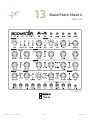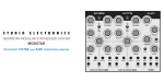
1
LIMITED WARRANTY TERMS AND CONDITIONS
This Limited Warranty applies only to ANALOGIA INC./STUDIO ELECTRONICS purchased in the United States
of America. Outside the USA, warranty policy and service is determined by the laws of the country of purchase
and followed by our local authorized distributor. A listing of our authorized distributors is available at http://www.
studioelectronics.com/shop/distributors/
ANALOGIA INC./STUDIO ELECTRONICS warrants to the first owner of a covered product purchased directly
from ANALOGIA INC./STUDIO ELECTRONICS, or an authorized ANALOGIA INC./STUDIO ELECTRONICS
dealer in the U.S., that this product will be free from defects in materials and or workmanship for a period of
one year from the date of purchase. Please register this product online at http://studioelectronics.com/support/
registration/ to establish the date of purchase (NOT A REQUIREMENT FOR WARRANTY SERVICE BUT A
GOOD IDEA).
To exercise your rights under this Warranty as the first owner/purchaser, YOU MUST SHIP THIS PRODUCT
IN ITS ORIGINAL PACKAGING (which we can replace and send to you for $10) at your expense, with
proof of purchase documentation and the ANALOGIA INC./STUDIO ELECTRONICS supplied power
adapter, to ANALOGIA INC. An RMA (Return Material Authorization) number from ANALOGIA INC./
STUDIO ELECTRONICS must be obtained first before returning any product. Email RMA requests to rma@
studioelectronics.com, or call us at (310) 640-3546 to secure an RMA #. Products shipped to ANALOGIA INC.
without an RMA will be refused and returned. Shipping insurance is optional, but highly recommended.
ANALOGIA INC./STUDIO ELECTRONICS will repair or replace this product at its sole option and at no charge
to you for parts and labor—when deemed necessary and within the warranty period—provided that ANALOGIA
INC./STUDIO ELECTRONICS reserves the right to determine whether the product is “defective” for purposes
of this Limited Warranty. This Warranty does not apply if damage to this product occurrs as a result of abuse or
misuse, abnormal use or handling, improper packaging, another product’s interaction, exposure to temperature
extremes, or if the product has been altered or modified/customized in any way, or the damage was caused by
unauthorized repair or service. The original product must return to ANALOGIA INC. unaltered.
IN NO EVENT SHALL ANALOGIA INC./STUDIO ELECTRONICS BE LIABLE FOR ANY INDIRECT,
INCIDENTAL, COLLATERAL, EXEMPLARY, PUNITIVE, CONSEQUENTIAL OR SPECIAL DAMAGES OR
LOSSES ARISING OUT OF YOUR PURCHASE OF PRODUCTS AND/OR OUT OF THIS WARRANTY,
INCLUDING WITHOUT LIMITATION, LOSS OF USE, PROFITS, GOODWILL OR SAVINGS OR LOSS OF
DATA, MUSIC, ELECTRONIC FILES, OR PREFERENCES THAT MAY HAVE BEEN STORED BY A USER
OF THE PRODUCT, EVEN IF ANALOGIA INC./ STUDIO ELECTRONICS HAS BEEN ADVISED OF THE
POSSIBILITY OF SUCH DAMAGES OR CLAIMS. SOME STATES DO NOT ALLOW THE EXCLUSION OR
LIMITATION OF INCIDENTAL, PUNITIVE, OR CONSEQUENTIAL DAMAGES, SO THE ABOVE LIMITATION
OR EXCLUSION MAY NOT APPLY TO YOU.
This Limited Warranty and the right of replacement is in lieu of any and all other warranties—which you hereby
waive—and it gives U.S. purchasers specific legal rights. You may also have other rights which vary from State
to State.
ANALOGIA INC., 530 West Palm Ave. El Segundo, CA 90245
Studio Electronics Boomstar Manual
Limited Warranty
CIRCUIT AND SOFTWARE DESIGN
Tim Caswell
USER INTERFACE AND FEATURE SPECIALIST
Greg St. Regis
SOUND PROGRAMMING AND DEMOS
Drew Neumann Greg St. Regis Marc St. Regis
GRAPHIC DESIGN
John Greczula
PRIMARY ANALOG CONSULTANT
Drew Neumann
LEAD VENDOR LIAISON
Daniel Wendell
QUICK START GUIDE MANUAL
Marc St. Regis Greg St. Regis Camille St. Regis Daniel Wendell
VERY SPECIAL THANKS
Mary St. Regis Geoff Farr Rachael Herbison Lucy Bauer
Rev. 2.0, 5.3.2014
Information contained in this Boomstar Manual is subject to change without notice and does not represent a commitment on behalf of ANALOGIA
INC. No portion of this manual may be produced or transmitted in any form, or by any means—whether electronic or mechanical, or for any purpose
other than purchaser’s personal use—without the explicit written permission of ANALOGIA INC. All other products, logos or company names
mentioned herein are trademarks or registered trademarks of their respective owners.
© ANALOGIA INC. 2014. All Rights Reserved.
A N A L O G I A I N C.
530 West Palm Ave., El Segundo California 90245
Tel: (310) 640-3546 Web: studioelectronics.com Email: @sbcglobal.net
facebook.com/StudioElectronics • twitter.com/SE_BoomStar • youtube.com/user/StudioElectronics
soundcloud.com/studio-electronics
Studio Electronics Boomstar Manual
ii
Credits
BOOMSTAR OPERATION MANUAL
1) The Design Behind the ‘Stars . . . . . . . . . . 1
5.2.17 MIXER . . . . . . . . . . . . . . . . . . . . . . . . . . . . . . . . . . . . . . . . . . 19
2) Setup Essentials . . . . . . . . . . . . . . . . . . . . . 2-6
2.1
2.2
2.3
2.4
5.2.14 Glide . . . . . . . . . . . . . . . . . . . . . . . . . . . . . . . . . . . . . . . . . . . 18
5.2.15 Dynamics . . . . . . . . . . . . . . . . . . . . . . . . . . . . . . . . . . . . . 19
5.2.16 ENV 1 • PW 1 - Envelope 1 to Pulse Wdth 19
Warnings, Precautions and Advice . . . . . . . . . . . 2-4
Product Registration . . . . . . . . . . . . . . . . . . . . . . . . . . . . . 4
Smart and Safe Connections . . . . . . . . . . . . . . . . . . . . 5
Boomstar Warming and Output Warning . . . . . 6
5.2.17.1
5.2.17.2
5.2.17.3
5.2.17.4
5.2.17.5
VCO 1 - Voltage Cont. OSC . . . . . . . . .
VCO 2 - Voltage Cont. OSC 2 . . . . . . .
Ring Mod - Ring Modulation . . . . . . . .
Noise . . . . . . . . . . . . . . . . . . . . . . . . . . . . . . . . . .
Feedback . . . . . . . . . . . . . . . . . . . . . . . . . . . . .
19
19
19
19
19
5.3 Back Panel . . . . . . . . . . . . . . . . . . . . . . . . . . . . . . . . . . . . 20-21
5.3.1 Connections, Switches, Warnings . . . . . 20-21
5.3.1.1 Audio Out . . . . . . . . . . . . . . . . . . . . . . . . . . . . . . . 20
3) Signal Flow Chart . . . . . . . . . . . . . . . . . . . . . . . 7
5.3.1.2 MIDI . . . . . . . . . . . . . . . . . . . . . . . . . . . . . . . . . . . . . 20
5.3.1.3 Power Adapter Connection . . . . . . . . . . 20
5.4 Side Panel . . . . . . . . . . . . . . . . . . . . . . . . . . . . . . . . . . . . . . . . 21
3.1 A Tim Caswell Original . . . . . . . . . . . . . . . . . . . . . . . . . . . . 7
5.4.1 Rack Mounting Holes . . . . . . . . . . . . . . . . . . . . . . . . 21
4) Patch Reset . . . . . . . . . . . . . . . . . . . . . . . . . . . . . . 8 6) Legal . . . . . . . . . . . . . . . . . . . . . . . . . . . . . . . . 22-23
4.1 Sawtooth Bass Patch - Factory Reset . . . . . . . . . . . 8
6.1
6.2
6.2
6.4
5) Panels . . . . . . . . . . . . . . . . . . . . . . . . . . . . . . . . 9-21
Liability . . . . . . . . . . . . . . . . . . . . . . . . . . . . . . . . . . . . . . . . . . . 22
FCC . . . . . . . . . . . . . . . . . . . . . . . . . . . . . . . . . . . . . . . . . . . . . 22-23
Canada . . . . . . . . . . . . . . . . . . . . . . . . . . . . . . . . . . . . . . . . . . . . 23
Europe . . . . . . . . . . . . . . . . . . . . . . . . . . . . . . . . . . . . . . . . . . . . 23
5.1 Front Panel . . . . . . . . . . . . . . . . . . . . . . . . . . . . . . . . . . . . . 9-10
5.1.1 Adjustment Holes . . . . . . . . . . . . . . . . . . . . . . . . . . 9-10
5.1.1.1 CV input tracking adjust. . . . . . . . . . . . . . . . 9
5.1.1.2 Oscillator 1 high tune adjust.. . . . . . . . . . . 9
5.1.1.3 Oscillator 1 octave adjust . . . . . . . . . . . . . . 9
5.1.1.4 Oscillator 1 initial tune adjust . . . . . . . . . 9
5.1.1.5 Oscillator 1 scale adjust . . . . . . . . . . . . . . . . 9
5.1.1.6 Oscillator 2 scale adjust . . . . . . . . . . . . . . . . 9
5.1.1.7 Oscillator 2 initial tune adjust . . . . . . . . . 9
5.1.1.8 Oscillator 2 high tune adjust . . . . . . . . . 10
5.1.1.9 Oscillator 2 octave adjust . . . . . . . . . . . . . 10
5.1.1.10 Envelope Drive . . . . . . . . . . . . . . . . . . . . . . . 10
5.1.1.11 VCA Offset . . . . . . . . . . . . . . . . . . . . . . . . . . . . . 10
5.1.1.12 VCA DC Balance . . . . . . . . . . . . . . . . . . . . . . 10
7) Glossary . . . . . . . . . . . . . . . . . . . . . . . . . . . . . . . . 24
5.2.1 SEM Controls . . . . . . . . . . . . . . . . . . . . . . . . . . . . . . . . . . 11
5.2.2 SE80 and 700 Controls . . . . . . . . . . . . . . . . . . . . . . . 11
5.2.3 Patch Points . . . . . . . . . . . . . . . . . . . . . . . . . . . . . . . 11-12
9) The Ancient Chinese . . . . . . . . . . . . . . . . . . 26
8) Filter Talkers . . . . . . . . . . . . . . . . . . . . . . . . . . . 25
8.1 Bace . . . . . . . . . . . . . . . . . . . . . . . . . . . . . . . . . . . . . . . . . . . . . . . 25
8.2 Drew Neumann . . . . . . . . . . . . . . . . . . . . . . . . . . . . . . . . . . 25
5.2 Top Panel . . . . . . . . . . . . . . . . . . . . . . . . . . . . . . . . . . . . . 11-19
5.2.3.1
5.2.3.2
5.2.3.3
5.2.3.4
5.2.3.5
5.2.3.6
CV IN - Control Voltage In . . . . . . . . . . . . . 11
GATE IN - Gate Input . . . . . . . . . . . . . . . . . . 11
VCF FM - VCF Frequency Mod In . . . . . 11
VCA AM - VCA Amplitude Mod In . . . . 11
OSC Out - Oscillator Output . . . . . . . . . . 11
EXT IN - External Input . . . . . . . . . . . . . . . . 12
10) Back Panel Art . . . . . . . . . . . . . . . . . . . . . . . . 27
5.2.4 VCO 1 - Voltage Controlled OSC 1 . . . . . . . . . 13
5.2.5 VCO 1 - Voltage Controlled OSC 2 . . . . . . . . . 14
5.2.6 VCF - Voltage Controlled Filter . . . . . . . . . . 14-15
5.2.7 ENV 1 - Envelope 1 . . . . . . . . . . . . . . . . . . . . . . . . 15-16
5.2.8 ENV 2 - Envelope 2 . . . . . . . . . . . . . . . . . . . . . . . . . . . 16
5.2.9 X MOD - Cross Modulation . . . . . . . . . . . . . . . . . . 17
5.2.10 LFO - Low Frequency Oscillator . . . . . . . 17-18
5.2.11 VCA - Voltage Controlled Amplifier . . . . . . . 18
5.2.12 Master Tune . . . . . . . . . . . . . . . . . . . . . . . . . . . . . . . . . . 18
5.2.13 Bend . . . . . . . . . . . . . . . . . . . . . . . . . . . . . . . . . . . . . . . . . . . 18
Studio Electronics Boomstar Manual
11) Troubleshooting . . . . . . . . . . . . . . . . . . . . . . 28
12) Blank Patch Sheet 1 . . . . . . . . . . . . . . . . . . 29
13) Blank Patch Sheet 2 . . . . . . . . . . . . . . . . . . 30
iii
Table of Contents
1
THE DESIGN BEHIND THE ‘STARS
As SE fans know, we’ve been doing the multiple filter thing for some time, and while our approach has never been
one of exact emulation of the original synthesizers—that could only be accomplished if the entire signal path were
cloned as well—the focus and purpose was, and remains, to bring the main essence—the “spirit” of the classic
originals into our own unique, performance-based platforms, and in the case of the Boomstar accomplish that
with as many hardware features, i.e., crossmod, ringmod, overdrive, feedback, that would fit! Judging from the
many flattering remarks (from owners, well-wishers, followers), and downright effusive praise, satisfaction has been
achieved—and thanks to all!
Critical Circuit Details: For oscillators we’ve essentially been using the same Moog-based design since our reissue
of the MiniMoog® stabilized oscillator board. In the Boomstar synths we replaced the Fairchild cans with 3046s,
which are stabilized with temperature compensating resistors placed on top—something very similar to what is in
an S.E.M: it gives us just the right amount of warmth and tuning stability. The Moog® filter employed in all our own
synths is a clone, except that in the Boomstar 5089, a 3046 replaces the original hand-matched transistors in the
top and bottom of the ladder. The resonance produced is lovely; it sits perfectly along with the signal, singing out,
but never dominates. The 4075, 3003, and S.E.M. are faithful to the original circuit designs, with some license taken
by Tim Caswell in case of the SE80 filter, due to 1970s custom filter ICs employed in Yamaha’s design. The VCA in the
BoomStar is the MiniM—g® VCA, which we used in the SE-1(X) as well, while the Omega and ATC series synths use
a VCA incorporating an LM13700, in case you were wondering.
These are “through-hole” (to be contrasted with “surface-mount”) and decidedly discrete analog synthesizers: the
Holy Grail of PCB assembly procedures, built to last and remain completely serviceable—bound to be necessary if
they stick around making people happy as long as we expect them to!
Greg St. Regis 5.3.14
El Segundo, CA USA
Studio Electronics Boomstar Manual
1
Design Behind the ‘Stars
2
SETUP ESSENTIALS
2.1 Warnings, Precautions, and Advice
WARNING - When using electric products basic precautions should always be followed to avoid the possibility
of serious injury or even death to you or others, as well as damage to the device or other property from electrical
shock, fire, or other risks. These precautions include, but are not limited to, the following “to do” list
• Read, save, and understand all of the instructions before using product.
• Do not use product near any water source—such as a bathtub, wash basin, kitchen sink, wet floor, or swimming
pool.
• Clean with a soft, dry cloth with unit unplugged from AC outlet.
• This product, either alone or in combination with an amplifier and headphones or speakers, may be capable of
producing sound levels that could cause permanent hearing loss. Do not operate for a long period of time at a high
volume level or at a level that is uncomfortable. If you experience any hearing loss or ringing in the ears, you should
consult an Audiologist.
• Do not place anything heavy on the instrument.
• The product should be situated so that its location or position does not interfere with its proper ventilation.
• The product should be located away from heat sources such as radiators, heat registers, or other items that
produce heat.
• Avoid using the product where it may be affected by dust or hot sunlight.
• Make sure the line voltage in your location matches the input voltage specifications on the DC power adapter.
• All Boomstar synth models use an external power adapter. No other power supply or adapter other than the one
provided by Analogia Inc./Studio Electronics is to be used under any circumstances. Analogia Inc./ Studio Electronics
accepts no responsibility for damage caused by use of an unauthorized power supply or adapter.
• Mute channel volume before making audio connections to prevent malfunction and speaker damage.
• Unplug power supply cord from outlet when not in use for an extended period.
• Do not trample the power supply cord, trip over it, or pull at it; grasp the plug portion when unplugging.
• Care should be taken so that objects do not fall and liquid is not spilled into the enclosure through openings.
• Protect the unit from strong jolts and vibration and never apply strong pressure to the front, back or side panels,
or strike them in any manner.
Studio Electronics Boomstar Quick Start Manual
2
Setup Essentials
The product should be serviced by qualified service personnel when:
a) The power supply cord or the plug has been damaged.
b) Solid objects or liquid either have fallen or spilled into the product.
c) The product has been exposed to rain.
d) The product does not appear to operate normally or exhibits a marked change in performance.
e) The product has been dropped, or the enclosure damaged.
• Do not attempt to service the product beyond that described in the user maintenance instructions. All other
servicing should be referred to qualified technicians.
DANGER – INSTRUCTIONS RELEVANT TO RISK OF FIRE, ELECTRIC SHOCK, OR INJURY TO
PERSONS: Do not open the chassis. There are no user serviceable parts inside. Refer all servicing to qualified
personnel only. All Boomstar synth models use an external power adapter. No other power supply or adapter other
than the one provided by Analogia Inc./Studio Electronics is to be used under any circumstances. Analogia Inc./
Studio Electronics accepts no responsibility for damage caused by use of an unauthorized power supply or adapter.
• Mute channel volume before making audio connections to prevent malfunction and speaker damage.
• Unplug power supply cord from outlet when not in use for an extended period.
• Do not trample on the power-supply cord, trip over it, nor pull at it, but grasp the plug portion when unplugging.
• Care should be taken so that objects do not fall and liquid is not spilled into the enclosure through openings.
• Protect the unit from strong jolts and vibration and never apply strong pressure to the front, back or side panels,
or strike them in any manner.
GROUNDING INSTRUCTIONS: This product must be grounded. If it should malfunction or break down,
grounding provides a path of least resistance for electric current to reduce the risk of electric shock. This product
is equipped with a cord with equipment grounding conductor and a grounding plug, which must be plugged into an
appropriate outlet that is properly installed and grounded in accordance with all local codes and ordinances.
DANGER - Improper connection of the equipment grounding conductor can result in a risk of electric shock. Check
with a qualified electrician or serviceman if you are in doubt as to whether the product is properly grounded. Do not
modify the plug provided with the product. If it does not fit the outlet, have a proper outlet installed by a qualified
electrician.
SAVE THESE INSTRUCTIONS!
Studio Electronics Boomstar Manual
3
Setup Essentials
TRADEMARKS: The STUDIO ELECTRONICS logo is a trademark of Analogia Inc./Studio Electronics. All other
trademarks included in the publication remain the property of their respective holders.
Specifications and appearances are subject to change without notice.
COPYRIGHT © 2014 ANALOGIA INC. / STUDIO ELECTRONICS
2.2 Registration
Registering your BOOMSTAR synth establishes your ownership (should there be a legal ownership dispute in the
future), which then secures access to Analogia Inc. Tech. Support and Warranty Service, and, if you so desire, to
product updates, related information, and promotional offers. As always, our RSS feed, News page, Facebook and
Twitter outlets are current and generally useful.
Please register this product online at http://studioelectronics.com/support/registration/
Studio Electronics Boomstar Quick Start Manual
4
Setup Essentials
2.3 Smart and Safe Connections
Always power-off all audio gear before making any connections. Failing to do so may damage your speakers, or
other audio equipment and possibly your Boomstar Synth.
After completing all connections, set all levels to 0. Power on the various devices with audio amplifier or monitoring
system last, then raise the volumes to an appropriate listening level.
a) Plug Boomstar +/-15 VDC power supply male 5 pin din plug into female 5 pin din connector mounted on the right
side of back panel, near bottom of synth (marked Pin 1/: Com...).
b) Plug female 3 prong IEC cable plug into +/-15 VDC power supply male 3 prong IEC socket.
c) Plug male 3 prong IEC cable plug into AC outlet.
Note: A switchable power strip is recommended and highly useful for power recycling.
BOOMSTAR POWER ADAPTER REMOVAL PROCEDURE:
a) Unplug female 3 prong IEC cable plug from +/-15 VDC power supply.
b) Unplug female 3 prong IEC cable plug from AC outlet.
c) Unplug Boomstar male +/-15 VDC power supply plug from female connector on the right side of back panel, near
bottom of synth (marked Pin 1/: Com...).
IMPORTANT WARNING: DO NOT POWER ON OR OFF THE BOOMSTAR BY ANY OTHER
METHOD THAN THAT SPECIFIED ABOVE TO PREVENT DAMAGE TO UNIT. BE CERTAIN
TO STRICTLY FOLLOW THE AFOREMENTIONED CONNECTION PROCEDURE CAREFULLY
AND ACCURATELY. THE IMPROPER CONNECTION AND DISCONNECTION OF THIS POWER
SUPPLY MAY RESULT IN DAMAGE TO SYNTHESIZER AND SUPPLY. THE OPERATOR
OF THIS SYNTHESIZER ASSUMES ALL RESPONSIBILITY AND LIABILITY. ANALOGIA
INC./STUDIO ELECTRONICS—OWNERS, OFFICERS, AND EMPLOYEES, ASSUME NO
RESPONSIBILITY OR LIABILITY FOR PERSONAL AND PROPERTY DAMAGE INCURRED DUE
TO ACCIDENT, CARELESS HANDLING, ABUSE OR MISUSE, IMPROPER CONNECTION AND OR
INSTALLATION, OR IMPROPER ELECTRICAL CONTACT OR GROUNDING. OWNERSHIP AND
OR USE OF BOOMSTAR SYNTHESIZER CONSTITUTES AN AGREEMENT WITH THESE TERMS.
Studio Electronics Boomstar Manual
5
Setup Essentials
2.4 Boomstar Warming & Output Warning
Once the Boomstar is powered up, its temperature-regulated Oscillators will attain optimal temperature stabilization
in 5 minutes at which point it is ready for tuning and accurate control of all parameters.
IMPORTANT WARNING: DO NOT PATCH OUTPUTS TO OUTPUTS! THE “AUDIO OUT” ON THE
BACK PANEL MUST NOT BE PATCHED TO THE “OSC OUT” PATCH POINT ON THE FRONT
PANEL.
Studio Electronics Boomstar Quick Start Manual
6
Setup Essentials
3
Studio Electronics Boomstar Manual
SIGNAL FLOW CHART
7
Signal Flow Chart
4
PATCH RESET
3.1 Sawtooth Bass Patch - Factory Reset
“We have talked to engineers,” and they advise starting (and returning to this “home base” when puzzled or lost) with
this very basic patch to begin one’s exploration of the Boomstar sound and structure.
Studio Electronics Boomstar Quick Start Manual
8
Patch Reset
5
PANELS
5.1 Front Panel
5.1.1 Adjustment Holes
These unmarked holes on the front panel are motherboard access points for calibration potentiometers, set by
none other than Greg St. Regis, or a trained factory tech, and tweaking them without a knowledge and familiarity
of their function could result in your Boomstar sounding and playing quite poorly; that being said, some interesting
drive and VCA offset settings can be tailored to one’s own preferences—proceed at own risk.
Xcelite model R3322 screwdriver, or exact equivalent is recommended.
IMPORTANT WARNING: ONLY AN ANALOGIA INC./STUDIO ELECTRONICS RECOMMENDED
SCREWDRIVER OR EXACT EQUIVALENT CAN BE USED TO CHANGE THE BOOMSTAR’S FRONT PANEL
ADJUSTMENT HOLE SETTINGS TO INSURE UNIT IS NOT DAMAGED. BE CERTAIN TO STRICTLY
FOLLOW THIS REQUIREMENT. AN IMPROPER TOOL, AND OR IMPROPER USE OF SAID TOOL MAY
RESULT IN SERIOUS DAMAGE TO SYNTHESIZER AND OR SERIOUS INJURY TO OPERATOR. THE
OPERATOR OF THIS SYNTHESIZER ASSUMES ALL RESPONSIBILITY AND LIABILITY. ANALOGIA
INC./STUDIO ELECTRONICS OWNERS, OFFICERS,AND EMPLOYEES ASSUME NO RESPONSIBILITY
OR LIABILITY FOR PERSONAL AND PROPERTY DAMAGE INCURRED DUE TO ACCIDENT, CARELESS
HANDLING, ABUSE OR MISUSE, IMPROPER CONTACT OR GROUNDING, OR IMPROPER TOOLS OR
THEIR IMPLEMENTATION. OWNERSHIP AND OR USE OF BOOMSTAR SYNTHESIZER CONSTITUTES AN
AGREEMENT WITH THESE TERMS.
Holes from left to right:
5.1.1.1
#1 CV input tracking adjust.
5.1.1.2
#2 Oscillator 1 high tune adjust.
5.1.1.3
#3 Oscillator 1 octave adjust.
5.1.1.4
#4 Oscillator 1 initial tune adjust.
5.1.1.5
#5 Oscillator 1 scale adjust.
5.1.1.6
#6 Oscillator 2 scale adjust.
Studio Electronics Boomstar Manual
9
Panels
5.1.1.7
#7 Oscillator 2 initial tune adjust.
5.1.1.8
#8 Oscillator 2 high tune adjust.
5.1.1.9
#9 Oscillator 2 octave adjust.
5.1.1.10
#10 Envelope Drive: Set to full for Minim—g; back off for more Oberh—m-like sound.
5.1.1.11
#11 VCA Offset: Uniform waveform adjust.
5.1.1.12
#12 VCA DC Balance: De-pops amplifier.
A detailed calibration video will be posted at http://studioelectronics.com/support/tutorials/#boomstar
Studio Electronics Boomstar Quick Start Manual
10
Panels
5.2 Top Panel
5.2.1 SEM Controls
NOTCH Sweeps the 12dB filter setting from low-pass to high-pass. The ON position enables
the BANDPASS filter mode, passing frequencies within a certain range and rejecting, or
attenuating frequencies outside that range.
5.2.2 SE80 and 700 Controls
The FREQ knob sets the hi-pass filter (cutoff) frequency: the greater the value, the fewer low
frequencies pass through.
The RESONANCE knob sets the filter resonance. The resonance, or “Q” emphasizes, or boosts
the cutoff frequency region, and makes the presence of harmonics more apparent.
5.2.3 Patch Points - Modular Synthesis Control—Anti-MIDI
5.2.3.1
Control Voltage Input: External sources for control would include Modular synthesizers, and step
sequencers; one volt per octave is the voltage specification.
5.2.3.2
Gate Input: External Gate Input; a +5 voltage source is required to open the voltage controlled amplifier—
the alternative to MIDI note on and off.
5.2.3.3
Voltage Controlled Filter Frequency Modulation Input: Use an external control voltage to modulate the
filter frequency; modulation in the audio range results in a more complex waveform.
5.2.3.4
Voltage Controlled Amplifier Amplitude Modulation: Use a control voltage to externally modulate
Amplifier amplitude for level adjustments and tremelo effects.
5.2.3.5
Oscillator Output: Combined pre-filter audio output of oscillator 1 and oscillator. Tone is pre-amplifier
and therefore constant. Send this signal to your DAW or mixer and use liberally or sparingly. The purity,
clarity and transparency of all frequencies concerned are quite apparent and lovely.
Studio Electronics Boomstar Manual
11
Panels
5.2.3.6
External Input: Takes an external audio source and processes it through the Boomstar’s filter and amplifier.
In order to hear the sound you will need to open the amplifier, with either a gate or a MIDI note. Patching
the OSC OUT to the EXT IN (pictured below) will add additional depth, harmonics, and distortion.
Studio Electronics Boomstar Quick Start Manual
12
Panels
5.2.4 VCO 2 - Voltage Controlled Oscillator 1
A word about the
Oscillators as a whole:
Oscillators are the Adam (and Eve) of Analog synthesis. An oscillator produces periodic or regularly repeating
waveforms, e.g., pitched sounds. The Oscillator’s tuning controls alter the frequency or pitch of the oscillators,
whereas its wave shape selectors determine the harmonic spectrum of the signal, its basic timbre, or tone
coloration. We here at Studio Electronics think Voltage Controlled Oscillators still sound best.
What do these tone colors sound like, you wonder?
Triangle: Fluty, with odd harmonics like the square wave, but its amplitude is quite
weak in comparison to its fundamental. The Triangle possesses more brilliance
than the similarly shaped sine wave.
Sine: The most elemental waveform with its smooth fundamental and limited
harmonics—perfect for sub waveforms, simple “worm” leads, and enriching and
thickening the sound.
Sawtooth: Bright, buzzy, brassy—the richest harmonically—features a very
smooth tone when a low-pass filter is engaged; it contains both even and odd
harmonics of the fundamental frequency.
Square: In its even state, it is a full bouncy sound—a bass beast for many. Near the
edges of its duty cycle, or width, It becomes a “clavi,” reedy, nasal sound, with odd
harmonics only.
The RANGE switch selects the octave: LO (low frequency—clicks and ticks below the audible range for humans; clicks
can make for very interesting rhythmic pulses and sequences), 32’, 16’, 8’, 4’, 2’. The LO setting of Oscillator 2 can be
employed as a very flexible modulator. These foot pitch numbers come from the lengths of organ pipes in the great
cathedrals and churches of old—half the length equals double the pitch.
The SYNC switch locks the pitch of Oscillator 2 to follow the pitch of Oscillator 1 in hard synchronization, so that OSC
2 will tune only to the harmonic frequencies of Oscillator 1. Intermediate frequencies of Oscillator 2 will produce
unusual, “metallic” wave shapes and timbres; both Oscillators sharing the same base frequency makes all of this
possible.
The SUB LEVEL switch selects a half or full volume octave down Square wave with a center off position—a common
feature of the Boomstar enabling quick escapes from more complex programming settings.
The WAVE MIX switch selects single waveform settings or blending combinations of Triangle or Saw with Sine or
Square waveforms. The center position is null, or off.
The PULSE WIDTH knob sets the width of the Square waveform, ranging from wide, square rectangular forms to
narrow, nasally tall skyscraper-like shapes. A classic Square wave dials in a little left of the 12 o’clock knob setting—
for that wonderfully warm and yet hollowed-out rubbery tone.
Studio Electronics Boomstar Manual
13
Panels
5.2.5 VCO 2 - Voltage Controlled Oscillator 2
The TRACK switch selects Oscillator 2’s pitch tracking response. The ON position is the “business as usual,” 1 volt per
octave default setting. The OFF position disconnects the pitch control of the keyboard so a fixed or static pitch can be
achieved, which is useful and expressive in a variety of ways, i.e., as a fixed value low frequency modulator when the
LO setting is employed, a “flanged,” “phasey” synced Oscillator timbre effect, or a non-tracking, static drone. Come up
with some of your own!
OSC 2’s RANGE switch functions identically to OSC 1’s RANGE switch for selecting the octave: LO (low frequency
inaudible clicks), 32’, 16’, 8’, 4’, 2’.
The WAVE switch selects the Sawtooth, Triangle, or fixed Square wave.
The coarse/fine TUNE knob sets the pitch, or synced harmonic value when the SYNC switch of Oscillator 1 is in the ON
position—a very potent tweaking hot spot! The range of the tune pot is increased when TRACK is off.
The MOD DEPTH knob sets the depth at which ENV 1, or ENV 2 modulates the frequency or pitch of 2.
5.2.6 VCF 2 - Voltage Controlled Filter
A word about the Filter:
The Boomstar’s unique, classic filter designs feature wide range
lowpass filters, and in the case of the 5089, 4075, and 3003 selfoscillating filters. The SEM features a notch that sweeps from
low-pass to high-pass, as well as a band-pass mode. The SE80 is a
multimode filter, with dual frequency and resonance controls, for the low-pass and high-pass response. The Filter
attenuates, or cuts off the higher frequency components—those which lie above the adjustable cutoff frequency—
and passes the lower frequency components of the audio signal. [see Filter Talk, p. 25]
The FREQUENCY knob sets this cutoff frequency: the lower the cutoff frequency, the less harmonic content the
waveform will retain after passing through the filter. A wave shape rounding and smoothing occurs as this cutoff
frequency is reduced.
The TRACK switch selects the filter tracking (sometimes called keyboard follow or keyboard scaling) to FULL, OFF, or
HALF. Filter tracking applies keyboard control voltage to the filter: more tracking, more brightness as you ascend the
keyboard. A FULL, tracking selection makes the low end and bassy and round, and the high end cut better with its
increased brightness, clarity, and edge.
The RESONANCE knob sets the filter resonance. The resonance, or “Q,” emphasizes, or boosts, the cutoff frequency
region making the presence of harmonics more apparent. The 5089 and 4075 filters will begin to self-oscillate as
the knob passes the 3 o’clock position. Resonance is a pure sine wave and can be used as a separate tone source.
Resonance is in fact negative feedback—a signature sound of subtractive synthesis.
Studio Electronics Boomstar Quick Start Manual
14
Panels
The ENV DEPTH (Envelope) knob sets the depth of the modulation amount
as it is applied to the filter cutoff frequency. The shape of the filter
envelope is determined by the contouring controls attack, decay, sustain,
and release; the amount or depth of the envelope contouring is
determined by this parameter. Note: If the MASTER/DRONE switch is set to
the Master position, then the filter frequency is modulated by ENV 2, not
ENV 1.
The MOD DEPTH knob sets the modulation amount of the filter by either VCO 2 (Voltage Controlled Oscillator 2), or LFO
(Low Frequency Oscillator), via the switch to its left. Oscillator 2 becomes an LFO when its range switch is set to its LO
position; in the higher range settings (8, 4, 2) audio frequency modulation (think vocal and metallic timbres/x-mod)
are achieved. The software-based LFO with its versatile, multiple waveforms can be synced to MIDI. [See pp. 17-18,
5.2.10]
5.2.7 ENV 1 - Envelope 1
A word about the Filter Envelope:
The filter envelope shapes the timbre and overtone content of the audio signal as it flows from the circuitry of the
mixer. This envelope or contour generator is used to dynamically move the cutoff frequency. It works as such: each
time a key is depressed an envelope or contour generator attached to the filter’s cutoff frequency is actuated, and
sends a control signal to the filter. The control signal rises at one rate, falls at a second rate, levels off at a certain
point, and then finally falls off at a third rate. These four parameters and their effect upon the cutoff frequency are
explained below.
The ATTACK knob sets the attack time. The attack time determines the initial segment of the envelope. The frequency
at which the contour begins is determined by the filter frequency setting, while the peak, which it reaches, is
determined by the filter frequency and Envelope 1 amount settings combined. Incrementing the ATTACK knob value
from “0 - 10” will result in the brightness of the sound increasing sharply at first, and then more gradually as the
attack time lengthens. Switching INVERT on reverses the behaviour of the normal ADSR envelope. During the attack
phase (beginning when the key is pressed), the sound fades from the maximum amplitude to zero; during the decay
phase, it rises to the value determined by the sustain setting; after the key has been released, the sound parameter
rises from sustain amplitude back to maximum amplitude: tricky and nice. Switching LOOP on causes the attack and
decay values to repeat or loop, transforming Envelope 1 into a quasi LFO. The sustain parameter is in effect as well.
The DECAY knob sets the decay time. The decay time determines the duration of the second segment of the envelope,
i.e., the fall from the attack peak to the sustain level. When repeatedly depressing a key and incrementing the value
from “0 – 10,” you will at first hear the brightness drop sharply after the initial attack. This drop will become more
gradual as the decay time lengthens.
The SUSTAIN knob sets the sustain level. The sustain level determines the filter frequency at which the envelope
“levels off” after the initial rise and fall. The frequency of the sustain level can be as high as the initial peak, in which
case there is no decay after the initial rise, or it can be as low as the frequency at which the envelope contour began.
The RELEASE knob sets the release time and is the fourth and final stage of the envelope contour. Finally, after the
Studio Electronics Boomstar Manual
15
Panels
initial rise and fall of the attack and decay times to the sustain level, the release time takes effect after the sustain
level segment, when the played key or note is lifted. The frequency at which the sustain level is set, falls to the initial
filter cutoff frequency level at the rate set by the release time.
5.2.8 ENV 2 - Envelope 2
A word about the Amplifier Envelope:
The volume of the audio signal, which passes through the VCA envelope, is contoured by the ENV 2 controls. Each
time a key is pressed, the envelope or contour generator attached to the amplifier is actuated, and sends a control
signal to the amplifier. Like the filter envelope control signal, the VCA envelope control signal is composed of the
same four segments: initial rise, decay, sustain level, and release time. The volume of the note is shaped according
to the settings of the envelope controls. These four parameters are shown below.
The ATTACK knob sets the attack time. The attack time determines the duration of the initial rise in volume to a peak.
Notice the sound take on different qualities as you increase from a short sharp attack to a long slow crescendo.
Switching INVERT on reverses the behaviour of the normal ADSR envelope... Wait this sound familiar: ENV 2’s invert
functions is an exact clone (what used to be called a carbon copy) of ENV 1’s. The LFO TRIG (Low Frequency Oscillator
Trigger) switch selection, triggers the “gate” of ENV 2: the amplifier envelope.
The DECAY knob sets the decay time. The decay time determines the duration of the drop in volume from the initial
peak to the sustain level. Shorter decay times will produce more percussive/snappy sounds, longer times open up
and stretch out the sound. Switching SINGLE TRIG (single trigger) on allows for the continuation of the decay cycle
through a legato, or multi-note phrase. Switching MULTI TRIG (multiple trigger) on forces the attack and decay cycle of
both ENV 1 and ENV 2 to restart with every key press, or note on command.
The SUSTAIN knob sets the sustain level. The sustain level determines the volume level at which the envelope contour
levels off after the attack and decay. Set at “0,” no sustain level is heard. Set at “5,” the contour diminishes to a low
volume. Set at “10,” no drop in volume is heard after the initial peak is reached. With DRONE on, the last note received
by the Boomstar—MIDI or CV—is indefinitely sustained. The MASTER switch setting makes ENV 2 modulate both the
filter and the amplifier. ENV 1’s controls are still active in that they can still modulate the frequency of Oscillator 2
and the pulse width of Oscillator 1. To restate for clarity’s sake: ENV 2 ’s knobs assume the Boomstar’s Attack, Decay,
Sustain, and Release values for both filter and amplifier: a tidy and retro sound styling that brings to mind certain
beloved analog keyboards from the ‘80s.
The RELEASE knob sets the release time. The release allows the sound to fade out at the time set, rather than
immediately upon release of a note or key. This “final decay” takes effect after the sustain level segment of the
envelope and “does work” after the playing, triggering, or sequencing is done.
Studio Electronics Boomstar Quick Start Manual
16
Panels
5.2.9 X MOD - Cross Modulation
A word about Cross Modulation:
Is it just another term for frequency modulation, as some say, or is it a magical plane
where seemingly bizarre, almost entirely unpredictable results bring chaotic freshness
to any electronic vision or experimentation? Yes. It can also be coaxed into creating vocal textures à la the ATC-1.
The VCO 2 DEPTH (Voltage Controlled Oscillator 2 Depth) sets the amount of Oscillator 2 frequency modulation to
Oscillator 1’s frequency (VCO 1 FREQ) or pulse width (VCO 1 PW). Oscillator 2 also becomes an LFO when its range
switch is set to its LO position; in the higher range settings (8, 4, 2) audio frequency modulation can create metallic,
clangourous, planetary, searing effects, vibrant “colors,” and “waves.” Pulse width modulation was a feature found
on the legendary Prophet 5 synth, an expressive modulator capable of subtle or dramatic movements in the width
of the square wave—a feature rarely found on non-modular analog synths to this day. Use the switch to the right of
the pot to select either.
5.2.10 LFO - Low Frequency Oscillator
A tardy word about Modulation as a whole:
Modulation is the use of a control signal to create an often repetitive pattern of pitch, level, or harmonic and
rhythmic content changes; it infuses sound with movement and color.
The shape of the Boomstar’s LFO is determined by the waveform that the software LFO outputs—selected by the
non-graduated WAVE knob, with the waveshapes being sine, triangle, reverse sawtooth, sawtooth, square, 10%
square, 90% square, slew random, and random. The amount of modulation is determined by either the MOD DEPTH
control, or modwheel—its speed, or rate, by the RATE knob.
The Boomstar’s LFO is assignable to VCO 1 PW, VCO 1 FREQ, VCO 2 PW, VCO 2 FREQ, and can be synchronized to MIDI via
the MIDI SYNC switch. Note: In the Filter section the LFO is assignable to filter frequency as well. [see p. 14, 5.2.6]
LFO Features and Functions in Review:
RATE: Sets the speed, which reaches audio frequency spectrum; MIDI SYNC ON locks
the LFO rate to clock: RATE sets the 12 MIDI sync beat divisions, i.e., 4 measures,
2 measures, whole note, 1/2 note, whole note triplet, 1/4 note, 1/2 note triplet,
Studio Electronics Boomstar Manual
17
Panels
1/8 note, 1/4 note triplet, 1/16 note, 1/8 note triplet, 1/16 note triplet; MIDI SYNC
OFF honors panel settings; WAVE: Selects the waveforms: sine, triangle, reverse
sawtooth, sawtooth, square, 10% square, 90% square, random 1, random
2; MOD DEPTH (x2): Sets the modulation depths—the destinations being VCO 1 PW
(Oscillator 1 Pulse Width), VCO 1 FREQ (Oscillator 1 Frequency), VCO 2 PW (Oscillator 2
Pulse Width), and VCO 2 FREQ (Oscillator 2 Frequency).
5.2.11 VCA - Voltage Controlled Amplifier
A word about Voltage Controlled
Amplification:
The authentic two-stage MiniM—g voltage controlled amplifier is what increases the strength of the audio signal,
e.g., an amplifier is used to control the loudness of the sound over a period of time so as to emulate the natural
amplitude, shape, and scope of a real instrument—wait a minute, an analog synthesizer is a real instrument!
The OVERDRIVE switch engages the overdrive circuit: in the top position it is on.
The VOLUME knob sets the master volume of the synthesizer.
5.2.12 Master Tune
Sets the master tuning for the unit: roughly + and - 7 semitones.
5.2.13 Bend
Sets the pitch bend range for the pitch bend controller. The full position allows one octave up and down.
5.2.14 Glide
Sets the exponential hardware glide value—a classic “less is more” in all cases unless sweeping slowly
through octaves. The Boomstar’s glide is hardware, so it accessible via CC.
5.2.15 Dynamics
Play hard. Hear hard. Routes the MIDI velocity expression of your playing or sequencing to the
ENV DEPTH parameter.
Studio Electronics Boomstar Quick Start Manual
18
Panels
5.2.16 ENV 1 • PW 1 - Envelope 1 to Pulse Width
Sets the amount of ENV 1 (Envelope 1) modulation and the pulse width of Oscillator 1. To set modulation
to the full range of the pulse width, set the pulse width to “0,” meaning all the way counter-clockwise,
and then set the parameter to “10,” or all the way clockwise.
5.2.17 Mixer
5.2.17.1
Sets the mix level of Oscillator 1: default setting should be 75% of full, after which point a bit of
“browning out” occurs if both Oscillators are in use at that level—not a bad thing at all. Our MIDIMINI
distorts in just the same gleeful way. The SEM filter will get brown a tad earlier near 65% of full, due to its
lower input threshold.
5.2.17.2
Sets the mix level of Oscillator 2. Default setting should be 75% of full if a clean sound is in order [see
previous]. Otherwise, employ at full strength.
5.2.17.3
Sets the mix, or “heterodyne” of OSC 1 and OSC 2, and outputs the sum and difference of the
frequencies present in each waveform—tech-y. Expect to hear tones thick in harmonics and suitable for
producing bell-like/warm, metallic sounds, and “startpage” heterodyne right away, along with that other
thing you just remembered.
5.2.17.4
Sets the mix level of the Noise circuit. Default setting should be 0, unless you like hash with your bash.
5.2.17.5
Sets the level of positive feedback (a Drew Neumann NAMM 2013 term/spontaneous tutorial). A feature
similar to this was the best trick of the old Minim—g: running the unit back into itself. We repackaged
that as a pre-patched sweetening, screaming, and fully addictive tweak and twist necessity.
Studio Electronics Boomstar Manual
19
Panels
5.3 Back Panel
5.3.1.1
Standard high impedance instrument level output.
5.3.1.2
The MIDI OUT connection functions as a thru as well.
The MIDI IN is self-explanatory. The OVERFLOW switch
sets the MIDI overflow parameters for chaining
multiple Boomstar synths together. To do this, activate
the first unit’s OVERFLOW switch, and the last unit in the
“chain” OVERFLOW switch disengaged. Note: For proper
usage of a single Boomstar, make certain the OVERFLOW switch is deactivated, or the note buffer will be reduced to 0,
and note dropouts will occur with legato playing; however, OVERFLOW function can be useful when the Boomstar is
used in conjunction with a hardware step sequencer, which may or may not send the appropriate note-off
commands. The MIDI LEARN switch sets the MIDI channel: play on the channel desired, press the LEARN switch
momentarily, release, and the Boomstar “learns” the channel. Note: Boomstar OS software prior to Version 2 does
not remember the channel after powering down. Upon powering up those Boomstars, the channel received defaults
to MIDI channel one. All Boomstars with serial numbers 100,343 are equipped with Verson 2 OS.
5.3.1.3
— Excludes Boomstars manufactured to run only on 100 VAC for the Japanese market—
FOLLOWING THE BOOMSTAR POWER ADAPTER CONNECTION PROCEDURE IS ESSENTIAL TO
THE PROPER FUNCTIONING OF YOUR UNIT—DON’T DAMAGE YOUR BOOMSTAR AND VOID
YOUR WARRANTY BY “HOT-SWAPPING” THE POWER TO THIS SYNTHESIZER!
The proper power connection, disconnection procedure and IMPORTANT WARNINGS
(as previously detailed on pp. 11 - 12 of this manual):
BOOMSTAR POWER ADAPTER CONNECTION PROCEDURE
a) Plug Boomstar +/-15 VDC power supply male 5 pin din plug into female 5 pin din connector mounted on the
right side of back panel, near bottom of synth (marked Pin 1/: Com...).
b) Plug female 3 prong IEC cable plug into +/-15 VDC power supply male 3 prong IEC socket.
c) Plug male 3 prong IEC cable plug into AC outlet.
a) Unplug female 3 prong IEC cable plug from +/-15 VDC power supply.
b) Unplug female 3 prong IEC cable plug from AC outlet.
c) Unplug Boomstar male +/-15 VDC power supply plug from female connector on the right side of back panel,
near bottom of synth (marked Pin 1/: Com...).
IMPORTANT WARNING: DO NOT POWER ON OR OFF THE BOOMSTAR BY ANY OTHER METHOD THAN THAT
SPECIFIED ABOVE TO PREVENT DAMAGE TO UNIT. BE CERTAIN TO STRICTLY FOLLOW THE AFOREMENTIONED
CONNECTION PROCEDURE CAREFULLY AND ACCURATELY. THE IMPROPER CONNECTION AND DISCONNECTION
Studio Electronics Boomstar Quick Start Manual
20
Panels
OF THIS POWER SUPPLY MAY RESULT IN DAMAGE TO SYNTHESIZER AND SUPPLY. THE OPERATOR OF THIS
SYNTHESIZER ASSUMES ALL RESPONSIBILITY AND LIABILITY. ANALOGIA INC./STUDIO ELECTRONICS—
OWNERS, OFFICERS AND EMPLOYEES—ASSUME NO RESPONSIBILITY OR LIABILITY FOR PERSONAL AND
PROPERTY DAMAGE INCURRED DUE TO ACCIDENT, CARELESS HANDLING, ABUSE OR MISUSE, IMPROPER
CONNECTION, INSTALLATION, OR IMPROPER ELECTRICAL CONTACT OR GROUNDING. OWNERSHIP AND OR
USE OF BOOMSTAR SYNTHESIZER CONSTITUTES AN AGREEMENT WITH THESE TERMS.
5.4 Side Panel
5.4.1
Holes allow for rackmount bracket kit to be attached. Contact us at [email protected] for further info.
Studio Electronics Boomstar Manual
21
Panels
6
LEGAL
6.1 Liability
Neither Analogia Inc./Studio Electronics nor anyone else involved in the creation, production, or delivery of this
product shall be liable for any direct, indirect, incidental, special, consequential or punitive damages whatsoever
arising out of the use of this product, or inability to use this product; including without limitation: damages for loss of
business, profits, goodwill, business interruption, loss of business information, data or any other pecuniary loss, even
if Analogia Inc./Studio Electronics were previously advised of the possibility of such damages. Some states do not allow
limitations on the length of an implied warranty, or the exclusion or limitation of incidental or consequential damages,
so the above limitation and/or exclusions may not apply to you.
6.2 FCC
DO NOT MODIFY THE UNIT! This product, when installed as indicated in the instructions contained in this
manual, meets FCC requirement. Modifications not expressly approved by Analogia Inc./Studio Electronics may void
your authority granted by the FCC, to use this product.
IMPORTANT: When connecting this product to accessories and/or another product, use only high quality shielded
cables. Cable(s) supplied with this product must be used. Follow all installation instructions. Failure to follow
instructions could void your FCC authorization to use this product in the USA.
NOTE: This product has been tested and found to comply with the requirements listed in FCC Regulations, Part 15
for Class “B” digital devices. Compliance with these requirements provides a reasonable level of assurance that your
use of this product in a residential environment will not result in harmful interference with other electronic devices.
This equipment generates/uses radio frequencies, and if not installed and used according to the instructions
specified in this product’s operation manual, may cause interference harmful to the operation of aforementioned
other electronic devices.
Compliance with FCC regulations does not guarantee that interference will not occur in all installations. If this
product is found to be the source of interference (which can be determined by turning the unit “OFF” and “ON”),
please try to eliminate the problem by using one of the following measures:
• Relocate either this product or the device that is being affected by the interference.
• Utilize power outlets that are on different branch (circuit breaker or fuse) circuits or install AC line filter(s).
• In the case of radio or TV interferences, relocate/ reorient the antenna. If the antenna lead-in is 300 ohm ribbon
lead, change the lead-in to coaxial cable.
• If these corrective measures do not bring any satisfied results, please consult the local retailer authorized to
Studio Electronics Boomstar Manual
22
Legal
distribute this type of product. If you cannot locate the appropriate retailer, please contact Analogia inc.
These FCC statements apply only to those products distributed in the USA.
6.3 Canada
NOTICE: This class B digital apparatus meets all the requirements of the Canadian Interference-Causing Equipment
Regulation.
6.4 Europe
AVIS: Cet appareil numérique de la classe B respecte toutes les exigences du Règlement sur le matériel brouilleur
du Canada.
This product complies with the requirements for European Directive 89/336/EEC.
This product complies with the requirements of European Directive 89/336/EEC.
Studio Electronics Boomstar Manual
23
Legal
7
GLOSSARY OF ABBREVIATIONS
CV: Control Voltage
ENV: Envelope
EXT: External
FREQ: Frequency
IN: Input
LFO: Low Frequency Oscillator
LO: Low
MOD: Modulation
MULTI: Multiple
OSC: Oscillator
OUT: Output
PW: Pulse Width
SYNC: Synchronisation
TRIG: Trigger
VCA: Voltage Controlled Amplifier
VCF: Voltage Controlled Filter
VCO: Voltage Controlled Oscillator
WAVE: Waveform
Other Non-Screened Terminology:
“0”= all the way counter clockwise
“10”= all the way clockwise
Studio Electronics Boomstar Quick Start Manual
24
Glossary
8
FILTER TALKERS
8.1 Bace ([email protected])
MOOG: Creamy with great definition in the lower registers.
303: Mid range pronounced with clean clear resonance—squelchy.
ARP: Similar to Moog but less creamy and more grit—woolly.
SEM: Powerful mids. Not as deep as Moog but round and punchy, sinuous—searing.
8.2 Drew Neumann ([email protected])
The biggest differences between these filters are noticeable at higher resonance settings—that’s where most filters
reveal their character, but there’s more:
The Moog ladder has wonderful overdrive into the filter, wide-ranging resonance, (which does reduce gain a little bit
as resonance is increased) and a sharp -24db slope. Warm and fat.
The 303 is similar to the ladder, but one of the stages uses a different capacitor, and the resonance is chirpy and
mainly available in higher frequencies. It’s a bit buzzier than the Moog, and the cutoff slope isn’t quite as sharp. Acidy
is right.
The ARP filter is an integrator cascade—resonance is available over the entire range, and is quite pure sounding
(sine going to nearly triangle waves as it overdrives) which is why I like using the 4075 for deep drum and percussion
sounds. It’s dry sounding and organic, also great for very ethereal and rubbery sounds. It’s -24db, but not quite as
crisp in the high end as the ladder based designs. That’s normal...
The SEM filter is OTA based, and is -12db/octave. It is also a multi mode filter (highpass, lowpass, bandpass, notch,
and various mixes in between). It’s ballsy, crisp and clear, and gain actually increases with resonance, but the filter
will not go all the way to oscillation at high settings (due to parts tolerances, some might—but not all).
The CS80 filter pair is bright and buzzy, with a gently rolling cutoff slope, and really comes to life at higher resonance
settings. They are a resonant lowpass and a resonant highpass filter cascaded in series, which allows you to create
interesting vocal formant-type sounds. The sound is almost like a voltage-controlled sweepable parametric EQ.
Resonance on the CS80 never reaches self-oscillation, which is probably good because it would harm speakers,
neighbors, children and pets if it did.
In the SE80, add to this the overdrive, feedback and distortion capabilities, and you’ll be on a wild ride. Don’t forget
to take breaks from it to eat, drink, or sleep.
If you’re into Olympic skating, you really can’t go wrong with the SE80 Boomstar from Studio Electronics. It has all the quirky squirrelly vocal charm of the original without the kind
of weight problems that have ended many a skater’s careers. Sure, you can go spend $10,000 on a used, broken or poorly serviced example of the original, load it up on your sled
and try to haul its 220 lbs over that ice pond you’ve been using for triple Lutz practice. You’d fall through the ice, dam-it. YOU’D DIE!! DON’T DO IT!!! Get a Boomstar instead!
Studio Electronics Boomstar Manual
25
Filter Talkers
9
THE ANCIENT CHINESE
9.1 “Broom Star” ([email protected])
“Has anybody mentioned how “Boomstar” is a play on “broom star,” the ancient Chinese term for a comet?
vvvvvaThat keeps this synth name in the realm of cosmic/celestial objects, in the grand tradition...”
Thank you, controlvoltage—this is news to us!
Our research shows, in “The Records of the Grand Historian, or Shiji (or Shi Chi),” written more than a century later
‘round about midnight on one fine evening/day in 100 B.C., one can discover how the “broom star” [bristly tail yo], in
240 B.C. was “seen at the north direction and then at the west direction... during the summer the Empress Dowager
died.” Variant readings interpret its appearance in the east and movement north-ish. THE POINT BEING, the broom
star’s albedo, or reflection coefficient, derived from Latin albedo “whiteness” (or reflected sunlight), is the diffuse
reflectivity, or reflecting power, of its surface. Got it? And the STUDIO ELECTRONICS BOOMSTAR is fashionably
galactic, that midnight bit notwithstanding.
Studio Electronics Boomstar Quick Start Manual
26
Ancient Chinese
10
Studio Electronics Boomstar Manual
BACK PANEL
27
Back Panel
11
TROUBLESHOOTING
No Sound
Check all audio and MIDI connections—make sure the Boomstar is set to receive on the correct channel.
[see p. 20, 5.3.1.2]
Reset patch. [see p. 8, 3.1]
Check all MIDI channel settings. [see p. 20, 5.3.1.2]
Turn up master VCA volume. [see p. 18, 5.2.11]
Turn up Mixer VCO 1 and VCO 2 levels. [see p. 19, 5.2.17]
Turn on Waveform 1 Sawtooth. [see p. 13, 5.2.4] Turn off MIDI sync. [see 17, 5.2.10]
Turn off LFO trig. [see 16, 5.2.8] Soft Sound
Check all audio connections.
Turn up master VCA volume. [see p. 18, 5.2.11]
Turn up Mixer VCO 1 and VCO 2 levels. [see p. 19, 5.2.17]
Unwanted Distorted Sound
Select “I” position for VCA Overdrive (top position). [see p. 18, 5.2.11]
Set Feedback to “0.” [see p. 19, 5.2.17.5]
Unwanted Noise
Don’t be tasty with feedback—its lowest settings can add noticeable hash. [see p. 19, 5.2.17.5]
Unwanted Sustaining Sound
Turn off drone. [see pp. 16, 5.2.8]
Out of Tune
Set master tuning to 440 Hz. [see p.18, 5.2.12] Or one could experiment with 432 Hz, as was done here with our
Boomstar SEM: http://www.youtube.com/watch?v=aQza-J2kmUA&hd=1
Of esoteric interest perhaps: The speed of light, the human light body and the math: 432 squared—186,624—
is within 1 percent of the speed of light, currently measured as 186,282 miles per second. The square root of the
measured speed of light is 431.6. It’s also been claimed that the original Stradivarius violin was designed to be tuned
to 432—true? Who knows? ‘Tis amazing how much more beautiful music feels at the 432 concert pitch of Maestro
Verdi. [Also google “cymatics.” It’s prettyenough!]
Plain Lost
Reset patch. [see p. 8, 3.1]
Studio Electronics Boomstar Quick Start Manual
28
Trouble Shooting
12
Blank Patch Sheet 1
5089, 4075, 3003, SEM
Boomstar Patch Sheets - Rev. 1.2
© Analogia Inc. 2014
Studio Electronics Boomstar Manual
29
Blank Patch Sheet 1
13
Blank Patch Sheet 2
SE80, 700
Boomstar Patch Sheets - Rev. 1.2
© Analogia Inc. 2014
Studio Electronics Boomstar Quick Start Manual
30
Blank Patch Sheet 2