1
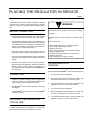
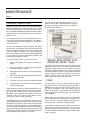
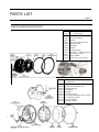
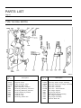
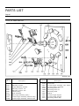
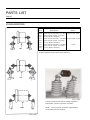
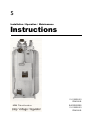
s
Installation / Operation / Maintenance
Instructions
21-115532-001
PR4018-06
SUPERCEDES
21-115532-001
PR4018-05
TABLE OF CONTENTS
Page
INTRODUCTION.............................................
Inspection for Damage in Shipment……….….
Special Features
Polarized Disconnect Switch
And Hinged Control Panel………….........…...
Remote Mounting of Control Equipment……..
Vari-AMPTM Position Indicator………………...
Operation at Less Than Rated Voltage….……
Forced Air Cooling……………………………...
Subbase Assembly……………………………..
Parts List
Major Components……………………………..
Position Indicator……………………………….
Type TLG Dial Switch…………………….…….
Type TLG Quick Break Mechanism…………..
Type TLF Dial Switch…………………………..
Type TLF Quick Break Mechanism…………..
Bypass Arresters……………………………….
Bushings…………………………………………
1
1
13
13
13
14
15
15
16
17
18
19
20
21
22
23
Page
Special Features
Polarized Disconnect Switch
And Hinged Control Panel……....………..…...
Remote Mounting of Control Equipment……..
Vari-AMPTM Position Indicator………………...
Operation at Less Than Rated Voltage….……
Forced Air Cooling……………………………...
Subbase Assembly……………………………..
Parts List
Major Components……………………………..
Position Indicator……………………………….
Type TLG Dial Switch……….………………….
Type TLG Quick Break Mechanism…………..
Type TLF Dial Switch…………………………..
Type TLF Quick Break Mechanism…………..
Bypass Arresters……………………………….
Bushings…………………………………………
13
13
13
14
15
15
16
17
18
19
20
21
22
23
For Emergency Service
Call: 1-800-241-4453
Siemens Power Transmission & Distribution, Inc.
THESE INSTRUCTIONS DO NOT PURPORT TO COVER ALL DETAILS OR VARIATIONS IN EQUIPMENT, NOR TO PR VIDE FOR EVERY
POSSIBLE CONTINGENCY TO BE MET IN CONNECTION WITH INSTALLATION, OPERATION OR MAl TENANCE. SHOULD FURTHER INFORMATION BE DESIRED OR PROBLEMS ARISE WHICH ARE NOT COVERED SUFI CIENTLY FOR THE PURCHASER’S PURPOSES, THE MATTER
SHOULD BE REFERRED TO YOUR SIEMENS POWE TRANSMISSION & DISTRIBUTION LLC REPRESENTATIVE.
THE CONTENTS OF THIS INSTRUCTION MANUAL SHALL NOT BECOME PART OF OR MODIFY ANY PRIOR OR EXI~ ING AGREEMENT,
COMMITMENT OR RELATIONSHIP. THE SALES CONTRACT CONTAINS THE ENTIRE OBLIGATION ( SIEMENS POWER TRANSMISSION &
DISTRIBUTION LLC. THE WARRANTY CONTAINED IN THE CONTRACT BETWEE THE PARTIES IS THE SOLE WARRANTY OF SIEMENS
POWER TRANSMISSION & DISTRIBUTION LLC. ANY STAT MENTS CONTAINED HERON DO NOT CREATE NEW WARRANTIES OR MODIFY
THE EXISTING WARRANTY.
INTRODUCTION
Page 1
Type JFR single-phase step-voltage regulators are designed
to give dependable service and to make installation, operation and maintenance as simple as possible.
QUALIFIED PERSON
Technology advances, especially in the realm of the control
apparatus, make it efficient to provide a separate instruction
manual for the Accu/StatTM control provided with this JFR Regulator. For specific control information, refer to the Accu/StatTM
control manual included with the regulator.
FOR THE PURPOSE OF THIS MANUAL AND PRODUCT
LABELS, A QUALIFIED PERSON IS ONE WHO IS FAMILIAR
WITH THE INSTALLATION, CONSTRUCTION AND OPERATION OF THE EQUIPMENT, AND THE HAZARDS INVOLVED.
IN ADDITION, HE HAS THE FOLLOWING QUALIFICATIONS:
WARNING
(a) Is trained and authorized to de-energize, clear, ground
and tag circuits and equipment in accordance with established safety practices.
(b) Is trained in the proper care and use of protective
equipment such as rubber gloves, hard hat, safety
glasses or face shields, flash clothing, etc., in accordance
with established safety practices.
(c) Is trained in rendering first aid.
This equipment contains hazardous voltages. Severe personal injury or property damage can result if
safety instructions are not followed.
To prevent:
Do not service or touch until you have de-energized
high voltage, grounded all terminals and turned off
control voltage. Grounding terminals with line to
ground capacitors may produce a small arc.
Only qualitifed personnel should work on or around
this equipment after becoming thoroughly familiar
with all maintenance procedures contained herein.
Distinctive signal words (DANGER, WARNING, CAUTION) are
used in this instruction book to indicate degrees of hazard
that may be encountered by the user. For the purpose of this
manual and product labels these signal words are defined
below.
DANGER
Indicates an imminently hazardous situation which, if not avoided, will result in death
or serious injury
WARNING
Indicates a potentially hazardous situation,
which, if not avoided, could result in death
or serious injury.
CAUTION
Indicates a potentially hazardous situation which, if not avoided, may result in
minor or moderate injury.
INTRODUCTION
Page 2
INSPECTION FOR
DAMAGE IN SHIPMENT
STORAGE PRIOR TO
INSTALLATION
Check each item with the shipping manifest immediately
upon receipt of the regulator. Make a thorough visual inspection of the regulator. Check for evidence of damage
attributable to mishandling in shipment. Should any shortage or damage be found, notify the local agent of the carrier
making the delivery and make appropriate notation on the
freight bill. A claim should be made immediately with the
carrier. Siemens should be notified
The regulator may be stored without any particular precautions or protection. Assure, however, that the control
compartment enclosure is tightly closed.
INTRODUCTION
PHYSICAL CONSIDERATIONS
•
Handling. Type JFR regulators are designed to be lifted
either by a forklift at the base or by use of hangar brackets
on the side of the tank. Each JFR regulator is provided
with either 2 or 4 lifting hooks on the side of the tank. The
number of hooks has been established to provide a margin of safety on lifting when all hooks provided are used.
WARNING
Page 3
•
For air cooled (OA) rating, derate kVA rating 0.4% for every
100 meters (330 feet) elevation above 1000 meters.
•
For forced air cooled (FA) rating, derate kVA rating 0.5% for
every 100 meters (330) feet elevation above 1000 meters.
LINE TERMINALS
AND CONNECTIONS
Type JFR voltage regulators are routinely equipped with line
bushing terminals per the following criteria.
Falling unit can cause severe injury or damage.
To prevent:
Do not use cover lifting eyes tolift complete unit.
Cover lifting eyes are for untanking of regulator only.
Lift complete regulator by using all side tank hooks.
•
Location. Type JFR regulators are designed for outdoor
installation. Any regulator may be platform or pedestal
mounted. Regulators provided with hangar brackets are
suitable for pole mounting. When the regulator is to be
installed in a substation on a pedestal it is recommended that a minimum elevation to the live connection
be established, as required by applicable codes.
Nameplate Line
Current Rating
Conductor Size Range
or Threaded Stud Size
50A to 300A
301A to 668A
669A to 1200A
1201 A to 2000A
#2 to 477 MCM
#2 to 800 MCM
1.125 - 12 UNF-2A
1.500 - 12 UNF-2A
Clamp type terminals for use through 668 ampere are
capable of accepting an aluminum or copper conductor.
Tank grounding provision consists of a 0.5-13NC
tapped hole in a steel pad for regulators rated to 300
amperes. Above 300 ampere ratings, a copper-faced
pad with two 0.5-13NC tapped holes is provided.
ELECTRICAL CONSIDERATIONS
DANGER
Hazardous high voltage is present at the line terminals
of the bushings on the cover of the regulator.
Type JFR regulators are commonly installed using any
of four electrical configurations.
•
One regulator in single-phase application. (Figure 4D)
•
Three regulators in wye on a grounded-neutral threephase system. (Figure 4D)
•
Two regulators in open delta on a three-phase
ungrounded system. (Figure 4B)
•
Three regulators in closed delta on a three-phase
ungrounded system. (Figure 4C)
Will cause severe injury or death.
To prevent:
Isolate the regulator before servicing.
•
Elevation. When the regulator will be used at an elevation
above 1000 meters (3300 feet) the kVA rating must be
reduced to assure operating temperature limits are not
exceeded.
Each of the four alternatives, when complete with switching
provisions, will take the electrical configuration as shown
on the next page.
The descriptions 'S', 'L', and 'SL' are embossed into the cover
for user convenience at time of installation.
INTRODUCTION
Page 4
INSTALLATION DIAGRAMS
(Figure 4A)
(Figure 4B)
(Figure 4B)
(Figure 4D)
INTRODUCTION
Page 5
PROTECTIVE MEASURES
Bypass Arrester. All JFR regulators are equipped with a
properly sized arrester, connected externally between the 'S'
and 'L' line terminals. The arrester is provided to protect the
series winding of the regulator from line surges. Of itself,
the bypass arrester does not provide lightning protection for
the regulator.
Lightning Protection. The number of lightning arresters used
will be a judgmental decision on the part of the user, considering such factors as isokeraunic level and degree of risk of
damage to be accepted. The minimum recommended lightning protection consists of a properly sized arrester between
the 'S' or 'L' bushing and ground on a single phase or a wye
connected system. A delta connection system requires the
use of two arresters to accomplish minimum protection levels. Additional protection can be obtained with the use of
arresters at both the 'S' and 'L' terminals in single phase or
wye systems and on all three terminals on a delta system.
For best results, install lightning arresters on the mounting
lugs adjacent to the bushings near the top of the tank. The
lugs are 0.5 - 13NC located on 2.5 inch centers. Ground the
arrester(s) and the regulator tank solidly to the same ground
connection. Be careful to keep the ground lead connections
as short as possible.
Thru Fault. Type JFR regulators are rated under condition of
thru-faults for twenty five times the OA rated current for 2
seconds or 40 times the OA rated current for 0.8 second to a
maximum of 20,000 amperes rms symmetrical. The fault
current may be asymmetrical to the extent that the peak of
the first current loop is equal to 2.26 times the rms value of
the current wave.
Figure 5A
For this purpose, it is necessary to use the nameplate
drawing and control diagram found in the control enclosure.
1. Refer to the Nameplate Diagram. A column is indicated
to connect lead P2 to P( ), based on the applicable
system voltage. The control diagram will aid in identification of the appropriate pin on the 19-pin terminal block.
The user is advised to provide for additional source impedance, bus sectionalizing or other means of limiting the available thru-fault current if these criteria are exceeded at the
installation
2.
CONTROL CONNECTIONS
Depending on the regulator, there may be a second
column indicating that lead U2 is to be connected to
U ( ). The same procedure is followed.
3.
For regulator equipped with fans for forced-air
cooling, another set of connections will be shown.
Many regulators can be used at several different nominal
system voltages. It is therefore necessary to assure that the
regulator is properly connected at the 19 pin upper terminal
block for the system voltage on which the particular regulator
will be used.
NOTE
Matters specifically relating to the Accu/
StatTM control used in conjuntions with the
regulator are not included in this manual.
Refer to the appropriate control instruction
manual.
CONNECTION DIAGRAMS
Page 6
CONNECTION DIAGRAMS
Page 7
CONNECTION DIAGRAMS
Page 8
PLACING THE REGULATOR IN SERVICE
Page 9
The following checks will be useful in assuring the regulator
is ready for use. The list cannot be all inclusive; careful attention on the part of a qualified operator remains imperative.
BEFORE CONNECTING
WARNING
High pressure or mechanical failure due to improper bypass operation can cause death, severe injury or damage.
To prevent:
•
Check oil level at oil sight window. If low, add sufficient
oil (ASTM D-3487 Type II) to bring level to that desired.
•
Check dielectric strength of the oil per ASTM D-877. If
found to be below 24 kV, filtering should be accomplished
and additional testing of oil integrity is justified. Note:
This is not necessary if regulator is being installed immediately upon receipt from the factory.
•
Take power factor reading of all bushings (common)
against ground (tank). Reading should be less that 2.0%.
•
Verify from the nameplate that the unit is connected for
the proper output voltage, motor voltage and control panel
voltage.
•
Assure that the regulator is on the neutral tap position.
This should be accomplished by observing the position
indication pointer and by powering the control from a
120V external source and observing the NeutraliteTM to
be illuminated.
Energize regulator only with regulator on neutral tap position.
Follow instructions:
1. Make certain regulator is in neutral (N) position.
2. Turn voltage source switch to "OFF".
3. Remove power fuse.
4. Close, sequentially, the source and load switches.
5. Open the bypass switch.
6. Visually observe that bypass circuit has opened.
7. Replace power fuse.
8. Place voltage source switch to normal.
CHECKING REGULATOR
OPERATION
(Refer to applicable Accu/StatTM Control instruction manual.)
CONNECTING
•
•
•
1.
Turn the transfer switch to MANUAL.
Identify 'S', 'L' and 'SL' bushings on the cover. Make electrical connections per the appropriate installation diagrams, page 4, first connecting 'SL' bushing.
2.
Run the tapchanger in the lower direction, at least until
the control is observed to go out of band "LOW".
3.
Set Vari-AmpTM limits on position indicator, if necessary.
See Page 11.
Turn the transfer switch to AUTO. After a time delay, the
regulator will return to an "IN" band condition.
4.
Turn the transfer switch to MANUAL.
5.
Run the tapchanger in the raise direction, at least until
the control is observed to go out of band "HIGH".
6.
Turn the transfer switch to AUTO. After a time delay, the
regulator will return to an "IN" band condition.
Set Accu/StatTM Control as desired. See Accu/StatTM
instruction manual
SWITCHING THE REGULATOR
"ON THE LINE"
It is absolutely imperative that the regulator be on the neutral
tap position before switching the regulator on the line.
REMOVING THE REGULATOR FROM SERVICE
Page 10
REMOVING THE REGULATOR
FROM THE LINE
In order to remove a regulator from service without dropping
load, it is imperative that the regulator be on the neutral position. The system must first be de-energized (load dropped)
before removal. If the regulator being removed is in a closed
delta bank, it is necessary to bypass and isolate all regulators in the bank. The routine removal procedure is essentially the reverse of the procedure used to place the regulator
on the line.
WARNING
High pressure or mechanical failure due to improper bypass operation can cause death, severe injury or damage.
To prevent:
Bypass regulator only with regulator on neutral tap position.
Follow instructions:
1. Run the regulator under normal voltage source to the
neutral position, as revealed by the tap position indicator.
2. Confirm via the NeutraliteTM indicator that the regulator is on neutral. If the independent checks of the position indicator and NeutraliteTM indicator do not confirm the neutral position, bypassing must not be attempted. In such event, de-energize the system to remove the regulator from service.
3. After assuring that the regulator is on neutral, close
the bypass switch.
4. Open, sequentially, the load and source switches.
5. (a.) For a single phase or grounded wye connection,
make sure that the high voltage disconnect switches
are opened.
(b.) For a closed delta connection, be sure all regulators in the bank are bypasses and isolated.
6. Exercise appropriate care in the removal of the
regulator. High voltage will still be present at the
bypass witch and the source and load switch
terminals. Remove the ground connection last.
MAINTENANCE
Page 11
GENERAL INSTRUCTIONS
Failure to properly maintain the regulator can result in severe personal injury and product failure. The instructions
contained herein should be carefully reviewed, understood
and followed. The following maintenance procedures should
be performed regularly:
1. Operational checks
• Control performance
• Tapchanger performance
• Vari-AmpTM limit performance.
2. Periodic inspection
• Oil sample
• Oil oxidation inhibitor addition
• Contact wear
• Fans
This checklist does not represent an exhaustive survey of
maintenance steps necessary to ensure safe operation of
the regulator. Particular applications may require further procedures. Should further information be desired or should
particular problems arise which are not covered sufficiently
for the purchaser’s purposes, the matter should be referred
to the local Siemens sales representative.
When powered, dangerous voltages are present in the equipment that can cause severe personal injury, death, and product failure. Always de-energize and ground the equipment
before maintenance requiring access to high voltage parts.
The use of unauthorized parts in the repair of the equipment,
tampering by unqualified personnel, or faulty repair and adjustments will result in dangerous conditions which can
cause severe personal injury or equipment damage. Follow
all safety instructions contained herein.
OPERATIONAL CHECKS
Basic regulator operation can be checked while the regulator remains in service. Simply provide means to observe the
output voltage (such as a voltmeter connected at the test
terminals).
• Observe that the voltmeter reads the voltage level setting
required by the control, to within one-half of the bandwidth tolerance. Note 1: The control must be “in” band.
Note 2: Line drop compensation must be set to zero if the
regulator is carrying load.
• Run the tapchanger several steps in one direction in the
manual mode until the output voltage is outside of the
bandwidth. Return the control to automatic mode. After
the predetermined time delay, the tapchanger motor will
be observed to return the output voltage in-band. Repeat
this operation, running the tapchanger in the opposite
direction.
• Check the Vari-AmpTM limit switches by attempting to run
the tapchanger beyond the position to which the switches
are set. The limit switches should function to open the
circuit. Note: If the limit switch is set at the maximum 10%
range and fails to function, the tapchanger will stall against
a mechanical stop. The motor is designed to stall continuously without damage
CAUTION
Operation of the regulator at extreme tap positions
could produce a line voltage above or below desired
operating limits at the load.
To prevent:
Operate the regulator only to judiciously determined
voltage extremes.
WARNING
Regulator may have High Internal Pressure. Can
cause serious personal injury or death, or damage to
the regulator.
To prevent:
Use pressure relief valve to vent regulator before
untanking.
MAINTENANCE
Page 12
PERIODIC INSPECTION
A sample of oil from the regulator should be subjected to
dielectric breakdown test, per ASTM D-877. It is recommended that oil testing less than 24 kV be filtered. Other
tests, especially Neutralization Number, Interfacial Tension
and Power Factor are also useful and may be preferred by
particular users.
Contacts, both movable and stationary, show normal
burning and wear after 1,500,000 operations. If for any
reason A1 dimensions exceeds 4/5 of A, the stationary
contact should be replaced.
The oxidation inhibitor in the oil will be depleted over a period of a few years and should be replaced. The inhibitor is
2, 6-ditertiary-butyl-para-cresol (DBPC) at a concentration
level of 0.2 to 0.3%.
The time interval between internal inspections will depend
upon frequency of tapchanger operation and the load on the
regulator. Regulators subjected to numerous overloads and
a high load factor may require more frequent inspections
than those carrying normal loads. While internal inspection
is not a necessity, preventive maintenance inspections will
help assure the continuity of service.
To untank a JFR regulator, proceed as folllows:
1.
Remove the regulator from service as described on
Page 7.
2. Place the regulator in a position where energized
overhead lines will not interfere.
3.
Operate pressure relief valve to vent regulator before
untanking
4.
Remove the three mounting bolts holding the control
box onto the main tank.
5.
Loosen all cover bolts and turn outward 180 degrees.
6.
The regulator can now be pulled from the main tank
by the cover lifting eyes.
When inspecting, check to be certain all hardware and connections are tight. The principal point of the internal inspection will be the condition of the arcing contacts on the
tapchanger. Since numerous factors influence the rate of
contact tip wear, no one criteria can be stated to recommend when a contact should be changed.
The following figure shows the possible condition of contact wear after a period of operation. If a contact surface has
burned down so that only a 1/8 inch wide line contact area
remains, the contact will probably be giving adequate service at low contact temperatures, but much further deterioration will probably result in decreased spring pressure and
possibly faulty operation. Therefore, the contact should definitely be replaced. (See Figure in next column.)
•
SEALED REGULATORS WITH
PRESSURE RELIEF VALVE
If cover top cap is removed, make certain the cap is properly
sealed when replaced on cover. Siemens recommends applying pipe sealant (Loctite PST or equivalent) around the
threads of the adapter. Furthermore, it is recommended that
the seal be tested by applying 5 psig pressure through the
pressure relief valve fitting for 5 minutes, with no loss in
pressure. Failure to assure seal may allow moisture to be
pulled into the unit during a cool-down cycle.
• FANS
The fans used for cooling (on some regulators) require a
minimum of attention. Fans with plain sleeve bearings or
Oil-Lite sleeve bearings should be oiled at least once a
year with a good grade of SAE 10-W mineral engine oil
which does not thicken in cold weather. Oil must be added
to sleeve bearings before starting motor for the first time
after installation.
Fans equipped with ball bearing motors are packed with
grease before shipment and should be greased at least
once a year with a soda-soap, ball-bearing grease of medium consistency furnished by a reliable supplier.
For fans that are seldom used, the frequency for greasing or
oiling may be less than outlined above, but it is recommended that this lubrication be placed on a yearly schedule.
It is often possible to determine by inspection whether lubrication is required.
SPECIAL FEATURES
Page 13
POLARIZED DISCONNECT SWITCH
(JACK PLUG) AND HINGED
CONTROL PANEL
The Accu/StatTM control panel is hinged and may be removed completely from the regulator control box by removing the wing nuts on the polarized jack plug and pulling the
jack from its fixed portion. This will automatically de-energize
the control. It is not necessary to bypass or de-energize the
regulator to remove the control.
A spring-loaded shorting bar in the plug automatically short
circuits the current transformer secondary when the jack is
removed.
REMOTE MOUNTING
OF CONTROL
EQUIPMENT
The Accu/StatTM control may be
remotely mounted. Remote
cable is available in standard
lengths of 18, 25 and 30 feet
incorporating oil and moisture
resistant, color-coded conductors.
VARI-AMPTM POSITION INDICATOR
The Vari-AmpTM feature provides a method of operating the
regulator at increased load by decreasing the range of operation. It provides operator flexibility by allowing the range of
regulation to be adjusted in 1 1/4 percent increments. The
various regulation ranges together with the corresponding
current capacities for standard regulators are listed on page
11. All that is necessary to adjust the range of regulation
anywhere from ±5 percent to ±10 percent is to turn the adjusting knobs until the proper range of regulation is shown
on the side of the position indicator. The upper and lower
limits need not be the same.
It is not necessary to remove the regulator from service to
make this adjustment. The switches are, however, in the
motor power circuit so the motor should not be running while
the switches are being set.
SPECIAL FEATURES
Page 14
Catalog
OPERATION AT LESS
THAN
RATED VOLTAGE
JFR regulators may be operated at less
than the voltage for which they were designed. All system voltages for which
control system taps have been provided
are shown on the nameplate. When this
is to be accomplished it may be necessary to reconnect particular leads at the
upper 19-pin terminal block as illustrated
on page 5. When operating the regulator at reduced voltage it must be noted
that the regulator carries a maximum
current rating which rules regardless of
the voltage (see table at right). It may
therefore be necessary to operate the
regulator at less than its nameplate kVA
rating.
Units with catalog number starting with
10 are self cooled
11 are forced-air cooled
Regulators can be modified at factory for
50 Hz operation with appropriate derating
of voltage.
*Capable
of
carrying
current
corresponding to rated kVA when operated
at 7200/12470 volts grounds wye.
Number
VARI-AMPTM RANGE AND CURRENT RATINGS AVAILABLE
Includes
Voltage & kVA
±10%
±83/4%
±71/2%
10-02.5-050.0
10-02.5-075.0
10-02.5-100.0
10-02.5-167.0
10-02.5-250.0
10-02.5-333.0
11-02.5-416.3
200
300
400
668
1000
1332
1665
220
330
440
668
1000
1332
1665
240
360
480
668
1000
1332
1665
270
405
540
668
1000
1332
1665
320
480
640
668
1000
1332
1665
10-05.0-050.0
10-05.0-100.0
10-05.0-167.0
10-05.0-250.0
10-05.0-333.0
11-05.0-416.3
100
200
334
500
668
835
110
220
367
550
668
835
120
240
401
600
668
835
135
270
451
668
668
835
160
320
534
668
668
835
10-07.6-038.1
10-07.6-057.2
10-07.6-076.2
10-07.6-114.3
10-07.6-167.0
10-07.6-250.0
10-07.6-333.0
10-07.6-416.3
10-07.6-500.0
10-07.6-667.0
11-07.6-889.0
50
75
100
150
219/232
328/347
437/463
546/578
656
875
1167
55
83
110
165
241/255
361/381
481/509
601 /636
668
875
1167
60
90
120
180
263/278
394/416
524/556
656/668
668
875
1167
±61/4%
68
102
135
203
296/313
443/468
590/625
668/668
668
875
1167
68
135
203
270
±5%
80
120
160
240
351 /371
525/555
668/668
668/668
668
875
1167
10-13.8-069.0
10-13.8-138.0
10-13.8-207.0
10-13.8-276.0
50
100
150
200
55
110
165
220
60
120
180
240
80
160
240
320
10-14.4-072.0
10-14.4-144.0
10-14.4-288.0
10-14.4-333.0
10-14.4-432.0
10-14.4-576.0
10-14.4-720.0
10-14.4-833.0
50
100
200
231
300
400
500
578
55
110
220
254
330
440
550
636
60
120
240
277
360
480
600
668
68
135
270
312
405
540
668
668
80
160
320
370
480
640
668
668
10-19.9-100.0
10-19.9-200.0
10-19.9-333.0
10-19.9-400.0
10-19.9-667.0
10-19.9-833.0
50
100
167
200
335
418
55
110
184
220
368
459
60
120
201
240
402
502
68
135
226
270
452
565
80
160
268
320
536
668
SPECIAL FEATURES
Page 15
FORCED AIR COOLING
SUBBASE ASSEMBLY
Certain regulators may be equipped for forced-air cooling
and include fans mounted on the radiators. The fans are
usually automatically controlled by means of the change in
oil temperature (see Connection Diagram). The thermometer located in the top transformer oil contains two identical
switches which control fan operation when fan control
switch is in “Auto” position.
Subbase assemblies are available in 4-inch high increments
from 21 through 49 inches for most JFR regulators. The
proper height is selected by picking the elevation that will
provide required clearance from foundation to the live part of
the regulator bushing.
The switches are normally set to start the fans at 65°C and
to stop them at 55°C top oil temperature, but may be adjusted plus or minus 5°C.
A thermal overload relay is mounted on each fan motor. Any
fan that develops trouble will be automatically disconnected
from the line without affecting the other fans of the system.
One fan can be removed from the radiators without affecting
the operation of the others. When fans are out of service,
care must be exercised to prevent overloading the regulator.
Fan should be removed and replaced carefully to prevent
damage to the radiators.
Figure 15B
Figure 15A
PARTS LIST
Page 16
MAJOR COMPONENTS PARTS LIST
INSTRUCTIONS FOR ORDERING PARTS
When ordering parts give the quantity of parts required, the
regulator serial number, parts list item number, complete
description, and method of shipping. State whether for
emergency repair, maintenance, spare part, etc.
All shipments will be made F.O.B Factory
Item
01-11
5050A
5081
5083
5084
5085
5087
5088
5092
5094B
5095
5246
5287
17
80
81A
90A
Figure 16A
Description
Control Compartment Gasket
Main Cover Gasket
Pressure Relief Valve
Terminal Box Gasket
Nameplate
Sampling Device
Grounding Lug Terminal (not shown)
Terminal Block Clamp
Terminal Block Studs
Terminal Block Gasket
Motor Capacitor TLG
Motor Capacitor TLF
Drain Valve
Oil Sight Glass
Oil Sight Gauge Gasket
J-Bolt Assy - Stainless Steel
PARTS LIST
Page 17
POSITION INDICATOR PARTS LIST
Item
01-11
5083
5060
5061
5062
5065
5067
5068
5069
5071
5072
5073
5274
Item
01-11
5063C
5062C
5065C
5067C
5068C
5069C
5071C
5072C
5073C
5079C
Description
Position Indicator - Complete
Solenoid Housing
Gasket
Drag Hand Solenoid Coil
Adjusting Knob
Faceplate
Window
Clamping Ring
Vari-Amp TM Adjusting Switch
Limit Switch (each)
Flang Gasket
Spacer Ring (not shown)
Description
Position Indicator - Complete
Drag Hand Solenoid Coil
Adjusting Knob
Faceplate
Window
Clamping Ring
Vari-Amp TMAdjusting Switch (each)
Limit Switch (each)
Flange Gasket
Window Gasket
PARTS LIST
Page 18
TYPE TLG DIAL SWITCH
Item
01-11
*5320
*5320B
5317A
5321
5322
5323
5324
5325
5326
5327
Description
Phenolic Panel
Glass Polyester Panel
Reversing Main Shaft
Main Stationary Contacts
Reversing Stationary Contact R
Reversing Stationary Contact L
Neutral Stationary Contact
Collector Ring
Collector Hub
Reversing Switch Arm
Item
01-11
5328A
5328B
*5329
*5329A
*5329B
5330
5331
5332
5333
5334
5336
Description
Reversing Switch Finger Assembly
Reversing Switch Hub Finger Assembly
Drive Arm - Phenolic
Drive Arm - Phenolic
Drive Arm - Glass Phenolic
Hub Finger Support
Ring Finger Support
Main Moving Finger Assembly
Hub Finger Assembly
Ring Finger Assembly
Phenolic Drive Pin
PARTS LIST
Page 19
TYPE TLG QUICK BREAK MECHANISM
Item
01-11
*5320
*5320B
5317A
5321
5322
5323
5324
5325
5326
5327
Description
Item
01-11
Phenolic Panel
Glass Polyester Panel
Reversing Main Shaft
Main Stationary Contacts
Reversing Stationary Contact R
Reversing Stationary Contact L
Neutral Stationary Contact
Collector Ring
Collector Hub
Reversing Switch Arm
5328A
5328B
5329
5329A
5329B
5330
5331
5332
5333
5334
5336
Description
Reversing Switch Finger Assembly
Reversing Switch Hub Finger Assembly
Drive Arm - Phenolic
Drive Arm - Phenolic
Drive Arm - Glass Phenolic
Hub Finger Support
Ring Finger Support
Main Moving Finger Assembly
Hub Finger Assembly
Ring Finger Assembly
Phenolic Drive Pin
PARTS LIST
Page 20
TYPE TLF DIAL SWITCH
FIGURE 20A
Item
01-11
5351
5352
5353
5354
5355
5356
5357
5358A
5359
5360A
Description
Panel
Stationary Contact
Neutral Stationary Contact
Stationary Contact - LH
Stationary Contact - RH
Collector Ring
Shaft Assembly
Main Finger Assembly (each)
Contact Finger Assembly Collector Ring
Contact Finger Assembly Collector Hub
Item
01-11
*5363
5364
5365
*5366
5366A
5367
5368
5369
5370
5373
Description
Drive Plate
Contact Finger Assembly - Rev. Switch
Contact Support Assembly
Reversing Drive Pin
Reversing Drive Pin
Reversing Shaft
Spacer
Contact Finger Support
Contact Finger Support
Reversing Switch Stop
PARTS LIST
Page 21
TYPE TLF QUICK BREAK MECHANISM
Figure 21A
Item
01-11
5323A
5243B
5251
5252
5256
5257
5259
5260
5262
5263
5264
5265
Description
Counter Switch Assembly
Neutral Switch*
Mounting Frame
Motor
Drive Spring Tube
Drive Spring
Spacer
Notched Index Plate
Latch
Latch Spring
Latch Pin
Reversing Switch Drive Arm
*This neutral switch switch became effective
with type TLF-30D quick break mechanism.
Item
01-11
*5266
5267
5275
5276
5278
5285
5286
**5287
5288
5289
5290
5291
5600
Description
Interlock Disc and Drive Sprocket Assembly
Quick Break Mechanism Shaft
Actuating Arm Assembly
Spacer
A-Frame
Drive Chain for Position Indicator
Motor Sprocket
Motor Capacitor (may be located in control box)
Actuating Disc and Sprocket
Main Drive Chain
Position Indicator Drive Mechanism
Reversing Switch Spring Assembly
Flexible Shaft
*Include regulator serial number when ordering, and specify whether
brown phenolic or gray polyester material.
**Motor capacitor located in control box - effective with S/N 05582.
PARTS LIST
Page 22
BYPASS ARRESTERS
Item
01-11
Description
Volts
5420 Bypass Arrester Assembly 3 kV MOV
5421
5422
5423
5424
5425
5428
5428A
5429
2,500, 5,000, 7,620
Bypass Arrester Crystal, 3 kV MOV
Mounting Bracket Assembly
Bypass Arrester Assembly, 3 kV MOV 12,000-13,800-14,400
Bypass Arrester Crystal, 3 kV MOV
Mounting Bracket Assembly
Bypass Arrester Assembly, 6 kV MOV
19,920
Bypass Arrester Crystal, 6 kV MOV
Mounting Bracket Assembly
Include regulator serial number when ordering
Figure 22B
Polymer arresters now used on voltage regulators.
Supersedes previous porcelain arresters.
NOTE: 1.5 kV porcelain arresters superseded by
3.0 kV MOV polymer arresters.
Figure 22A
PARTS LIST
Page 23
BUSHINGS
Item
01-11
Description
5400P
Bushing Assembly for 15 kV
5400R
Bushing Assembly for 15 kV
5400S
Bushing Assembly for 15 kV
5401P
Bushing Porcelain for 15 kV
5401R
Bushing Porcelain for 15 kV
5401S
5410
5419
5411
5418
5426
Bushing Porcelain for 15 kV
Clamping Ring for 5400 and R Ratings
Clamping Ring for 5400S Rating
Cushion Spring
Cap Screw
Bushing Cap Line Terminal for
5400P Rating
Bushing Cap Line Terminal for
5400R and S Ratings
Gasket
Gasket
5430
5427
4034
kVA
50
38.1 thru 76.2
69 thru 138
50
100
114.3 thru 167
75
414
50
38.1 thru 76.2
69 thru 138
50
100
114.3 thru 167
75
414
Volts
5000
7620
13,800
2500
5000
7620
2500
13,800
5000
7620
13,800
2500
5000
7620
2500
13800
Figure 23A
PARTS LIST
Page 24
BUSHINGS
Item
01-11
Description
5400T
Bushing Assembly 15 kV
5400U
5400V
Bushing Assembly, 15 kV
Bushing Assembly, 23 kV
5400W
Bushing Assembly 15 kV
5400X
5400Y
Bushing Assembly, 23 kV
Bushing Assembly, 23 kV
5400YY
5400Z
5400AB
5400AC
5401T
Bushing Assembly, 15 kV
Bushing Assembly, 23 kV
Bushing Assembly, 23 kV
Bushing Assembly, 15 kV
Bushing Porcelain, 15 kV
5401U
5401V
Bushing Porcelain, 15 kV
Bushing Porcelain, 23 kV
5401W
Bushing Porcelain, 15 kV
5401X
5401Y
Bushing Porcelain, 23 kV
Bushing Porcelain, 23 kV
5401YY
5401Z
5401AB
5401AC
4025
Bushing Porcelain, 15 kV
Bushing Porcelain, 23 kV
Bushing Porcelain, 23 kV
Bushing Porcelain, 15 kV
Clamping Ring for 5400T
X, Z and AB Ratings
Clamping Ring for 5400U
V, W (SL Bushing only),
Y and YY Ratings
Clamping Ring for 5400W
Rating S and L Bushings only
Cushion Spring
Gasket
Gasket
Gasket
*Bushing Cap Line Terminal
for 5400T X, YY and AB Ratings
*Bushing Cap Line Terminal for
5400U, Y and Z ratings
*Bushing Cap Line Terminal
for 5400V Rating
Cap Screw
4026
4028
4030
4027
4032
4034
4035
5430
Figure 24A
5426
5418
kVA
100 thru 167
167
250 thru 509
207-276
72 thru 144
100 thru 200
333 thru 416.3
250 thru 416.3
576 thru 833
288
333 thru 400
333
333 thru 432
667 thru 833
667-889
100 thru 167
167
250 thru 509
207-276
72 thru 144
100 thru 200
250 thru 416.3
250 thru 416.3
576 thru 833
288
333 thru 400
333
333 thru 432
667 thru 833
Volts
2500
500
7620
13,800
14,400
19,920
2500
5000
14,400
14,400
19,920
12,000
14,400
19,920
7620
2500
5000
7620
13,800
14,400
19,920
2500
5000
14,400
14,400
19,920
12,000
14,400
19,920
7620
*Units rated 250 kVA and above, 2500 and 5000 volts are not supplied
with line terminals
Indicate Regulator Serial Number
s
Siemens Power Transmission & Distribution, Inc.
P.O. Box 6289
Jackson, MS 39288-6289
Phone: 601-939-0550
Fax: 601-939-3606
ACCU/STAT, DATA/PAK, NEUTRALITE
and VARI-AMP are trademarks of
Siemens Power Transmission &
Distribution, Inc.
PR4018-06
PR4018-05
PR4018-04
June/01
PRINTED IN U.S.A.