1
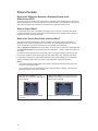
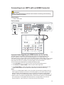
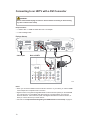
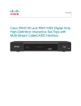
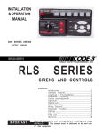
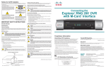
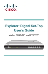
Explorer Digital Set-Top
User’s Guide
®
Models 4240HDC and 4250HDC
with Multi-Stream CableCARD Interface
TM
TM
TM
EXPLORER 4250HDC
CH+
SELECT
VOL+
VOL-
GUIDE
INFO
EXIT
POWER
CH-
SETTINGS
Notice to Installers
The servicing instructions in this notice are for use by qualiÞed service personnel only. To reduce
the risk of electric shock, do not perform any servicing other than that contained in the operating
instructions, unless you are qualiÞed to do so.
Note to System Installer
For this apparatus, the coaxial cable shield/screen shall be
grounded as close as practical to the point of entry of the cable
into the building.For products sold in the US and Canada, this
reminder is provided to call the system installer's attention to
Article 820-93 and Article 820-100 of the NEC (or Canadian
Electrical Code Part 1), which provides guidelines for proper
grounding of the coaxial cable shield.
CAUTION: To reduce the risk of electric shock, do not
remove cover (or back). No user-serviceable parts
inside. Refer servicing to qualified service personnel.
WARNING
TO PREVENT FIRE OR ELECTRIC SHOCK, DO NOT
EXPOSE THIS UNIT TO RAIN OR MOISTURE.
This symbol is intended to alert you that uninsulated voltage
within this product may have sufficient magnitude to cause
electric shock.Therefore, it is dangerous to make any kind of
contact with any inside part of this product.
Ce symbole a pour but d’alerter toute personne qu’un contact
avec une pièce interne de ce produit, sous tension et non isolée,
pourrait être suffisant pour provoquer un choc électrique. Il est
donc dangereux d’être en contact avec toute pièce interne de
ce produit.
This symbol is intended to alert you of the presence
of important operating and maintenance (servicing)
instructions in the literature accompanying this product.
Ce symbole a pour but de vous avertir qu’une
documentation importante sur le fonctionnement et
l’entretien accompagne ce produit.
20070131 SysInstaller 820 US/Canada/Intl
U.S. Patents
A patent notice is afÞxed to this product. In addition, the product may also be covered by one or
more of the following patents:
4,498,169, 4,692,919, 4,748,667; 4,829,569; 4,866,770; 4,885,775; 4,888,799; 4,890,319; 4,922,456; 4,922,532; 4,924,498; 4,965,534; 4,991,011;
5,003,384; 5,012,510; 5,029,207; 5,045,816; 5,053,883; 5,054,071; 5,058,160; 5,142,575; 5,142,690; 5,146,526; 5,155,590; 5,214,390; 5,225,902;
5,225,925; 5,235,619; 5,237,610; 5,239,540; 5,241,610; 5,247,364; 5,255,086; 5,257,403; 5,267,071; 5,270,809; 5,271,041; 5,272,752; 5,282,028;
5,285,497; 5,287,351; 5,301,028; 5,309,514; 5,317,391; 5,319,709; 5,341,425; 5,347,388; 5,347,389; 5,357,276; 5,359,601; 5,361,156; 5,367,571;
5,379,141; 5,379,145; 5,381,481; 5,390,337; 5,400,401; 5,406,558; 5,418,782; 5,420,866; 5,420,923; 5,425,101; 5,428,404; 5,430,568; 5,434,610;
5,436,749; 5,438,370; 5,440,632; 5,442,472; 5,455,570; 5,457,701; 5,471,492; 5,477,199; 5,477,262; 5,477,282 5,477,370; 5,481,389; 5,481,542;
5,485,221; 5,493,339; 5,497,187; 5,500,758; 5,502,499; 5,506,904; 5,519,780; 5,539,822; 5,550,825; 5,579,055; 5,579,057; 5,583,562; 5,592,551;
5,596,606; 5,600,378; 5,602,933; 5,640,388; 5,657,414; 5,675,575; 5,684,876; 5,715,515; 5,724,525; 5,734,822; 5,740,300; 5,742,677; 5,754,940;
5,757,416; 5,771,064; 5,774,859; 5,825,829; 5,826,167; 5,850,305; 5,854,703; 5,870,474; 5,892,607; 5,920,626; 5,923,755; 5,930,024; 5,930,515;
5,937,067; 5,963,352; 5,966,163; 5,982,424; 5,991,139; 5,999,207; 6,005,631; 6,005,938; 6,016,163; 6,028,941; 6,029,046; 6,052,384; 6,055,244;
6,072,532; 6,105,134; 6,148,039; 6,157,719; 6,188,729; 6,195,389; 6,212,278; 6,215,530; 6,219,358; 6,240,103; 6,243,145; 6,246,767; 6,252,964;
6,272,226; 6,292,081; 6,292,568; 6,320,131; 6,374,275; 6,405,239; 6,411,602; 6,417,949; 6,424,714; 6,424,717; 6,433,906; 6,438,139; 6,463,586;
6,467,091; 6,476,878; 6,493,876; 6,510,519; 6,516,002; 6,516,412; 6,526,508; 6,538,595; 6,546,013; 6,560,340; 6,567,118; 6,570,888; 6,622,308;
6,629,227; 6,664,984; 6,667,994; 6,671,879; 6,674,967; 6,678,891; 6,714,598; 6,721,352; 6,721,956; 6,725,459; 6,738,982; 6,744,892; 6,744,967;
6,751,271; 6,760,918; 6,795,972; 6,802,077; 6,804,708; 6,811,447; 6,817,028; 6,822,972; 6,823,385; 6,832,386; 6,845,106; 6,868,473; 6,874,075;
6,889,191; 6,909,471; 6,917,622; 6,917,628; 6,922,412; 6,927,806; 6,928,656; 6,931,058; 6,937,729; 6,969,279; 6,971,008; 6,971,121; 6,978,310;
6,986,156; 6,988,900; 6,996,838; 7,010,801; 7,053,960; 7,065,213; 7,069,578; 7,069572; D348065; D354959; D359737; D363932; D390217;
D434753; D507240; D507535; D513407; D516518; RE36368; RE36988
20070417 Patents
Contents
Important Safety Instructions ................................................................................iv
Welcome............................................................................................................... 1
Safety First ........................................................................................................... 1
For More Information ............................................................................................ 1
Identify Your 4240HDC or 4250HDC .................................................................... 1
What’s in the Carton? ........................................................................................... 2
Additional Equipment You Might Need ................................................................. 2
What’s on the Front Panel? .................................................................................. 3
What’s on the Back Panel? .................................................................................. 4
Connecting the Set-top ......................................................................................... 5
Connections for an HDTV and VCR ..................................................................... 6
Connections for a Standard-DeÞnition TV and VCR ............................................ 7
View Television Programming .............................................................................. 8
Performance Tips ................................................................................................. 9
Frequently Asked Questions............................................................................... 10
Picture Formats ...................................................................................................11
Connecting to an HDTV with an HDMI Connector ............................................. 12
Connecting to an HDTV with a DVI Connector................................................... 13
Connecting to an HDTV with Component Input (PrPbY) .................................... 14
Connecting to a Home Theater System with Component Input (PrPbY)............ 15
Connecting to a Stereo VCR and HDTV (optional) ............................................ 16
Connecting to an HDTV with a 1394 Connector................................................. 17
Connecting the Set-top in HD Mode to an SDTV with
Component Input (PrPbY) .................................................................................. 17
Index ................................................................................................................... 18
Compliance Information........................................................................Back Cover
iii
IMPORTANT SAFETY INSTRUCTIONS
Read These Instructions
Keep These Instructions
Heed All Warnings
• Location of the antenna-discharge unit
• Connection to grounding electrodes
• Requirements for the grounding electrodes
(see the following antenna grounding diagram
as recommended by NEC ANSI/NFPA 70)
Follow All Instructions
Power Source Warning
A label on this product indicates the correct
power source for this product. Operate this
product only from an electrical outlet with the
voltage and frequency indicated on the product
label. If you are uncertain of the type of power
supply to your home or business, consult your
service provider or your local power company.
Ground the Product
WARNING:
Avoid electric shock and Þre hazard!
Do not defeat the safety purpose of
the polarized or grounding-type plug.
A polarized plug has two blades with
one wider than the other. A groundingtype plug has two blades and a third
grounding prong. The wide blade or the
third prong is provided for your safety.
If the provided plug does not Þt into
your outlet, consult an electrician for
replacement of the obsolete outlet.
If this product connects to coaxial cable wiring,
be sure the cable system is grounded (earthed).
Grounding provides some protection against
voltage surges and built-up static charges.
Outdoor Grounding System
If this product connects to an outdoor antenna
or cable system, be sure the antenna or cable
system is grounded (earthed). This provides
some protection against voltage surges and
built-up static charges.
Article 810 of the National Electric Code (NEC)
ANSI/NFPA No. 70-1990, provides the following
information:
• Grounding of the mast and supporting
structure
• Grounding the lead-in wire to an antenna
discharge unit
• Size of the grounding conductors
iv
WARNING:
Avoid electric shock and Þre hazard! Do
not locate an outside antenna system in
the vicinity of overhead power lines or
power circuits. Touching power lines or
circuits might be fatal.
Protect the Product from Lightning
For added protection, unplug this apparatus
during lightning storms or when unused for long
periods of time. In addition to disconnecting the
AC power from the wall outlet, disconnect the
signal inputs.
Verify the Power Source from the
On/Off Power Light
When the on/off power light is not illuminated,
the apparatus may still be connected to the
power source. The light goes out when the
apparatus is turned off, regardless of whether
it is still plugged into an AC power source.
Eliminate AC Mains Overloads
WARNING:
Avoid electric shock and Þre hazard!
Do not overload AC mains, outlets,
extension cords, or integral convenience
receptacles. For products that require
battery power or other power sources
to operate them, refer to the operating
instructions for those products.
IMPORTANT SAFETY INSTRUCTIONS, continued
Prevent Power Cord Damage
Protect the power cord from being walked on
or pinched, particularly at plugs, convenience
receptacles, and the point where the cord exits
from the apparatus.
Provide Ventilation and Select a
Location
• Do not block any ventilation openings. Install
in accordance with the manufacturer’s
instructions.
• Do not place this apparatus on a bed, sofa,
rug, or similar surface.
• Do not place this apparatus on an unstable
surface.
• Do not install near any heat sources such
as radiators, heat registers, stoves, or other
apparatus (including ampliÞers) that produce
heat.
• Do not install this apparatus in an enclosure,
such as a bookcase or rack, unless the
installation provides proper ventilation.
• Do not place entertainment devices (such as
VCRs or DVDs), lamps, books, vases with
liquids, or other objects on top of this product.
Protect from Exposure to Moisture
and Foreign Objects
Do not use this apparatus near water.
WARNING:
Avoid electric shock and Þre hazard! Do
not expose this product to liquids, rain,
or moisture.
WARNING:
Avoid electric shock and Þre hazard!
Unplug this product before cleaning.
Clean only with a dry cloth. Do not use
a liquid cleaner or an aerosol cleaner.
Do not use a magnetic/static cleaning
device (dust remover) to clean this
product.
WARNING:
Avoid electric shock and Þre hazard!
Never push objects through the
openings in this product. Foreign
objects can cause electrical shorts that
can result in electric shock or Þre.
Accessories Warning
WARNING:
Avoid electric shock and Þre hazard!
Only use attachments/accessories
speciÞed by your service provider or
the manufacturer.
Service Warnings
WARNING:
Avoid electric shock! Do not open
the cover of this product. Opening or
removing the cover may expose you
to dangerous voltages. If you open the
cover, your warranty will be void. This
product contains no user-serviceable
parts. Refer all servicing to qualiÞed
service personnel.
Servicing is required when the apparatus has
been damaged in any way, such as a powersupply cord or plug is damaged, liquid has been
spilled or objects have fallen into the apparatus,
the apparatus has been exposed to rain or
moisture, does not operate normally, or has
been dropped.
Check Product Safety
Upon completion of any service or repairs to this
product, the service technician must perform
safety checks to determine that this product is in
proper operating condition.
Protect the Product when Moving It
Always disconnect the power source when
moving the apparatus or connecting or
disconnecting cables.
WARNING:
Avoid personal injury and
damage to this product! Use
only with the cart, stand, tripod,
bracket, or table speciÞed by the
manufacturer or sold with the apparatus.
When a cart is used, use caution when
moving the cart/ apparatus combination to
avoid injury from tip-over.
20070320 Set-Top Cable US & Canada
v
Welcome
The Explorer® 4240HDCTM and 4250HDCTM Digital Interactive Set-Tops with a Multi-Stream
CableCARDTM (M-CardTM) provide high-deÞnition (HD) capability and broadband digital video
services.
Follow the instructions in this guide to install the 4240HDC or 4250HDC, to become familiar with
the buttons on the front panel, and to access your cable services. Then, enjoy the features of the
4240HDC or 4250HDC and change the way you watch TV!
Safety First
Before using the set-top, read the Important Safety Instructions section of this guide.
For More Information
The consumer support website provides news and information about this product. For more
information, please refer to the following Web address:
http://www.scientiÞcatlanta.com/products/consumers/new_cableboxes.htm
Identify Your 4240HDC or 4250HDC
To Þnd the serial number for your 4240HDC or 4250HDC, look on the back for a label that is similar
to the example shown here. The serial number begins with “STB SN“ and is located beneath the
bar code.
STB SN: SABNFSRVG
eCM MAC: 001868C16907
STB RF MAC: 001868C16906
Serial Number
T13039
If your 4240HDC or 4250HDC requires troubleshooting in the future, your service provider may ask
for this serial number.
Use the space provided here to record the serial number:
____________________________________________
1
What’s In The Carton?
The set-top carton contains the following items:
EXPLORER 4250HDC
CH+
SELECT
GUIDE
VOL+
VOL-
INFO
EXIT
POWER
SETTINGS
CH-
• 4240HDC or 4250HDC Set-top
• Connection Guide
• Component Video Cables (PrPbY)
• Power Cord
• Audio Left/Right Cable
Additional Equipment You Might Need
You might need some of the cables and adapters shown below for connecting the set-top to your
home entertainment devices. See the connection information beginning on page 12 for more
information.
Check with your service provider for information about acquiring cables or adapters, or you can
purchase cables or adapters at your local electronics supplier.
Multi-Stream
CableCARD
(obtain from your
service provider)
S-Video
Cable
HDMI-to-HDMI
Cable
HDMI-to-DVI
Cable
RF Coaxial
Cable
Composite
A/V Cables
RGB Adapter
Cable
(RCA to RCA)
RGB Adapter
Cable
(RCA to BNC)
Optical Digital
Audio Cable
Coaxial Digital
Audio Cable
HDMI
Adapter
RGB
Adapter
RGB Adapter
Cable
(RCA to VGA)
IEEE 1394
6-Pin
to 4-Pin
Cable
IR Extender
Cable
2
What’s on the Front Panel?
EXPLORER 4250HDC
CH+
SELECT
GUIDE
VOL+
VOL-
INFO
EXIT
POWER
SETTINGS
CH-
T12966
1
2
3
4
5
6
7 8 9 10
11
12
1 Power
Turns the set-top on and off
2 VOL +, VOL -
Increases and decreases the volume
3 CH+, CH -
Scrolls up and down through the channels
4 Select
Provides access to your on-screen selection
5 IR Sensor
Receives the infrared signal from the remote control
6 LED Display
Displays the selected channel number and time of day. The LED also
displays the following:
)
• Message (
• HDTV
• Power (
)
• Output Resolution (1080i, 720p, 480p, or 480i)
• AUTO (Automatically outputs native scan rates that your TV can accept)
7 Guide
Accesses on-screen services, such as the on-screen guide, video-ondemand, or pay-per-view
8 Info
Displays a description of the selected program. This button is available
from the on-screen guide and while viewing a program
9 Exit
Exits menus, the on-screen guide, and program information
10 Settings
Provides access to the Settings menu
11 Smart Card Slot
Reserved for future use
12 USB Port
Connects to external equipment, such as a keyboard or mouse
(reserved for future use)
Note: This illustration may vary from the actual product.
3
What’s on the Back Panel?
MULTI-STREAM CABLE CARD
STB SN: SABNFSRVG
L
Pr
AUDIO OUT
eCM MAC: 001868C16907
CAUTION
Pb
RISK OF ELECTRIC SHOCK
DO NOT OPEN
AVIS: RISQUE DE CHOC
IR
STB RF MAC: 001868C16906
ELECTRIQUE NE PAS OUVRIR
R
CABLE
IN
T12967
THIS DEVICE IS INTENDED TO
BE ATTACHED TO A RECEIVER
THAT IS NOT USED TO RECEIVE
OVER-THE-AIR BROADCAST
SIGNALS. CONNECTION OF THIS
DEVICE IN ANY OTHER FASHION
MAY CAUSE HARMFUL
INTERFERENCE TO RADIO
COMMUNICATIONS AND IS IN
VIOLATION OF THE FCC RULES,
PART 15.
1
Y
CABLE
OUT
HDTV
2
3
DIGITAL
AUDIO OUT
4
VIDEO
OUT
120 VAC
60HZ 400W
S - VIDEO
OPTICAL
OUT
AUDIO OUT
CATV CONVERTER
MADE IN MEXICO
5 67 8 9
USB
10 11 12
1394
1394
13
120 VAC
60HZ 40W
LISTED 14H1
CABLE EQUIP.
14 15
1 Cable In
Connects to a coaxial cable that delivers the signal from your service
provider
2 Cable Out
Connects to a coaxial cable that sends analog audio and video signals to
a TV or VCR. These signals are standard-deÞnition TV (SDTV) video and
stereo audio
3 HDTV
Connects to the component video input (YPbPr) on the HDTV, when in HD
mode
4 Digital Audio Out
Connects to an RCA cable that sends a digital audio signal to a surroundsound receiver or other digital audio device
5 Out 2 (Secondary
Video/ Audio Out)
Connects to either a VCR or to another set of inputs (composite) on
your TV
6 Audio Out
(Left, Right)
Connects to RCA cables that send analog audio signals (left and right) to
the stereo inputs on a TV
7 S-Video Out
Connects to an S-Video cable that sends an S-Video signal to your TV or
VCR. This signal is standard deÞnition, but higher quality than other SDTV
connections
8 IR
This connector reserved for future use
9 Optical Audio
Output
Connects to an optical cable that sends a digital audio signal to a surroundsound receiver or other digital audio device
10 HDMI
Connects an HDMITM cable to the HDMI input of an HDTV. HDMI supports
both digital audio and video. May be used to connect to a DVI interface
using an HDMI-to-DVI adaptor for video and separate audio connections.
Any of the following audio connections may be used: Digital Audio Out (4);
Audio Out: Left, Right (6); or Optical Audio Output (9)
11 Multi-Stream
CableCARD
Slot for Multi-Stream CableCARD (M-Card) module, which decrypts
subscription digital channels. This set-top will not operate correctly without
an M-Card module. Obtain an M-Card module from your service provider
12 USB
Connects to external USB devices such as a keyboard or a mouse
13 1394
Connects to display devices that are equipped with a 1394 input
14 AC Outlet
Connects to the AC power cord from another device, such as a TV
15 AC Power Input
Connects to the power cord to deliver power to the set-top
Note: This illustration may vary from the actual product.
4
Connecting the Set-top
To connect your set-top to your entertainment devices, complete these steps.
1
Determine if your
TV is HD or SD and
whether it is wide
screen (16:9) or
standard screen
(4:3). See page 11
for more information.
16
4
or
9
3
Make the connections for your TV and/or VCR as follows:
2
!
3
• If you are using an HDTV, see page 6 and the connection diagrams at the end
of this guide.
• If you are using an SDTV, see page 7 and the connection diagrams at the end
of this guide.
• If you want to archive some programs to VCR tape, see pages 6 and 7 and the
connection diagrams at the end of this guide.
Identify the additional
devices you will connect
to the set-top and TV.
See pages 12 through
17 and the related user
guides for your devices
for more information.
DVD
VCR
Home Theater
D-VCR
Other
Plug the set-top and the TV into an AC power source that is not controlled by a
switch.
4
To provide some protection against voltage surges and built-up static charges
that can be caused by lightning storms and power outages, ground (earth) your
electronic devices, such as by plugging the set-top into a surge protector.
Do not turn on the set-top or TV yet.
POWER
5
It may take several minutes for the set-top to receive the latest software,
programming, and service information. Wait until you see one of the following
displays on the front panel of the set-top that indicates that the update is complete:
6
• Current time
• Four dashes (- - - -)
Note: If four dashes are displayed, you must call your service provider to get the settop authorized.
Set up your set-top for HDTV or SDTV by completing the following steps:
• Make sure the set-top is Off and the TV is On.
7
• On the front panel of the set-top, press GUIDE and INFO at the same time.
• Follow the on-screen instructions to choose HD or SD mode and wide screen
(16:9) or standard screen (4:3) depending upon your TV type. See page 11 for
more information on the scan rate.
• At the conclusion of the on-screen instructions, press POWER on the set-top to
begin watching TV.
5
Connections for an HDTV and VCR
To use the set-top with an HDTV, you must make one of the following connections to view the HD
content. In addition, you can make connections to a digital or analog VCR to record to a VCR tape.
Refer to your TV and VCR user’s guides and the cabling diagrams in this guide for more detailed
connection information.
Note: The labeling on your set-top may vary slightly.
DVI
HDMI
Required Connections to an HDTV (use one)
Some HDTVs have a High-DeÞnition Multimedia
Interface (HDMI) connector. The HDMI connector
provides both a digital video and audio connection. See
the connection diagram on page 12 for an example.
The HDMI connector can provide the connection to an
HDTV with a DVI input. If your HDTV has a Digital Visual
Interface (DVI) connector, you will need an HDMI-to-DVI
adapter, and you will need to connect a separate audio
connection.
OUT 1
See the connection diagram on page 13 for an example.
Adapter Needed
PrPbY
The PrPbY connectors can provide high-deÞnition
component video signals to an HDTV.
Note: Use the HD Setup Wizard on the set-top to set
the HD mode and select the output video format that will
matches the full capabilities of your HDTV.
RGB
1394
Some HDTVs have only RGB connectors. If you have
one of these HDTVs, you need an RGB adapter, and
you will need to connect a separate audio connection.
Check with your service provider for information about
acquiring an RGB adapter, or you can purchase the
adapter at your local electronics supplier.
Some HDTVs have 1394 connectors. If you connect to
your HDTV using a 1394 connection, you also need to
connect separate video and audio connections to your
HDTV.
See the connection diagram on page 17 for an example.
Optional Connections to a VCR (use one)
For VCRs with Video and Left and Right audio
connectors, you can use the Out 2 connectors
(Video, Left, and Right) on the set-top.
See the connection diagram on page 16 for an
example.
For VCRs with S-Video and Left and Right audio
connectors, you can use the S-Video Out and the
Out 2 Left and Right connectors on the set-top.
For Digital VCRs, you can use the 1394 out connector
on the set-top.
DVI
L
R
L
R
Pr
OUT 1
Y
Pb
L
Pb
Y
R
Pr
OUT 1
R
Pb
L
G
H
Y
R
B
V
See the connection diagram on page 14 for an example.
VCR
HDTV
Connections
Set-top
Connections
L
Pr
L
RGB Adapter
Needed
Pr
1394 OUT 1 Y
Pb
L Pb
Y
R
Set-top
Connections
R
R
1394
L
Pr
R
VCR
Connections
OUT 2
A
L U
D
I
RO
L
VIDEO
IN
R
AUDIO
IN
VIDEO
OUT 2
S-VIDEO
OUT
L
R
L
R
S-VIDEO
IN
1394
1394
6
Connections for a Standard-DeÞnition TV and VCR
When using the set-top with an SDTV, you must make one of the following connections to view
content. Some SDTVs may not have all these connections. In addition, you can make connections
to a VCR to record to a VCR tape. Refer to your TV and VCR user’s guides and the cabling
diagrams in this guide for more detailed information.
Note: The labeling on your set-top may vary slightly.
Required Connections to an SDTV (use one)
PrPbY
The PrPbY connectors can provide standard-deÞnition
component video signals to an SDTV.
Note: To connect PrPbY to an SDTV, you must set
the HD Setup Wizard on the set-top to HD Mode, and
select the output video format (typically 480i) that will
match the capabilities of your SDTV.
Set-top
Connections
SDTV
Connections
Pr
Y
Pb
Pb
Y
Pr
OUT 1
L
L
R
R
S-Video
The S-Video Out connection provides an optimal video
connection to SDTVs.
S-VIDEO
OUT
OUT 1
S-VIDEO
IN
L
R
L
Cable Out
R
The Cable Out connector provides a video and audio
connection to an SDTV.
VCR
Optional Connection to a VCR
For VCRs with Video and Left and Right Audio
connectors, you can use the Out 2 connectors (Video,
Left, and Right) on the set-top.
CABLE
OUT
CABLE IN/
ANT IN
Set-top
Connections
VCR
Connections
OUT 2
A
L U
D
I
RO
VIDEO
7
VIDEO
IN
L
R
AUDIO
IN
View Television Programming
Access Services and Programs
Access cable services and programs by pressing the following keys on the remote control:
• Guide–Access the on-screen guide. The on-screen guide displays schedules of TV programs
and other services available from your cable service provider, such as video-on-demand and
pay-per-view programs.
• Arrows–Select a program in the schedule.
• Info–Display a speciÞc program description (either from the on-screen guide or while viewing a
program).
• Select–View a speciÞc program in the guide.
Stretch and Zoom Program
You can stretch and zoom SD or HD programs by pressing the # key on the remote control.
Avoid Screen Burn-In!
Images such as letterbox bars or side bars, bright closed-captioning backgrounds, station logos, or
any other stationary images may cause the screen in your HDTV to age unevenly; this is known as
screen burn-in. Refer to the user’s guide that came with your HDTV for more information.
WARNING:
Avoid screen burn-in!
Do not display the same Þxed images on your HDTV screen for extended periods of time.
8
Performance Tips
If the set-top does not perform as expected, the following tips may help. If you need further
assistance, contact your service provider.
No Picture
• Verify that the power to your TV is turned on.
• Verify that your HDTV is in HD mode. If necessary, run the HD Setup Wizard to select HD mode.
• If the set-top is plugged into a wall switch, verify that the switch is in the ON position.
• Verify that all cables are properly connected.
• Verify that the M-Card module is installed.
• If your system includes a VCR or stereo, verify that you have properly connected them to the
set-top
• Verify that the set-top is set to the proper screen type and resolution.
No Color
• Verify that the current TV program is broadcast in color.
• Adjust the TV color controls.
• If you are using a component video connection (PrPbY), check that all connectors are
completely plugged into the set-top and TV.
No Sound
• If your setup includes a VCR or stereo, verify that you have properly connected them to the settop.
• Verify that the volume is turned up (analog audio only).
• Verify that the mute function is not on (analog audio only).
Automatic Software Updates
A message appears on the TV screen when the set-top and the M-Card module are receiving
software updates. In addition, download information also appears on the front panel of the set-top
during these updates. Wait for the current time to display on the front panel before continuing.
When the time appears, the update is complete.
9
Frequently Asked Questions
What is Digital Television?
Digital television (DTV) is a huge leap forward in television technology compared to analog
television that has been widely available since the 1940s. DTV is delivered and displayed using
digital encoding, similar to the way a PC operates. By using digital technology, there is no variation
in picture and sound quality from the origination point until it is displayed on your television. You
always receive a high-quality picture without the wavy lines or static you might sometimes get from
a weak analog signal.
Because DTV receives and displays digital images that contain many times more picture elements
(pixels - the small dots that make up the color image on your screen) than standard analog
television, you can get a sharper on-screen image than with analog. Additionally, DTV supports
CD-quality sound. DTV includes SDTV (Standard DeÞnition Television), EDTV (Enhanced DeÞnition
Television), and HDTV (High-DeÞnition Television). That means that all HDTV is digital, but not all
digital TV is high-deÞnition. A high-deÞnition program must originate in HD format and be broadcast
in HD format. Having an HDTV system does not mean that everything you watch will be in highdeÞnition. Getting the signal from digital cable also does not mean it is high-deÞnition.
What is Standard-DeÞnition Television?
Standard-deÞnition television (SDTV) is basic digital television programming delivered by cable.
Typically, the SDTV screen is the same, nearly square shape as an analog television screen. Digital
images on an SDTV set are crisp and clear—noticeably better than on a standard analog television
set using an antenna to receive over-the-air signals.
What is High-DeÞnition Television?
High-deÞnition television (HDTV) is a completely new way to send and receive television broadcast
signals. HDTV images are made up of pixels that are much smaller and closer together than those
used in standard analog television, and there are millions of them. Thus, HDTV can display Þve
to six times the detail of analog television to deliver picture quality that is much more realistic,
dimensional, and precise. SDTV programs can be viewed on an HDTV. Another feature of HDTV
is digital surround sound using Dolby® Digital, which is the same technology used to produce the
sound you hear in movie theaters.
Are Local TV Stations Broadcasting in HDTV?
Many local TV stations are transmitting digital signals. However, transmitting a digital signal does not
mean transmitting an HDTV signal. Some stations are using the new bandwidth to broadcast several
standard-deÞnition channels. Most stations, once they begin broadcasting in digital, are offering HD
content from their parent network (for example, CBS, ABC, NBC, Fox, WB, UPN, and PBS).
What is an M-Card Module?
An M-Card module is a CableCard that allows the set-top to decrypt subscription digital channels.
The module Þts into the Multi-Stream slot on the back of the set-top (see page 4 for the location of
the slot). You can obtain a an M-Card module from your service provider.
Note: Your service provider may provide this when you Þrst receive the set-top.
Where Are the Connection Diagrams?
The diagrams at the end of this guide show examples of common ways to connect the set-top to
your other electronic devices. However, these diagrams do not show every possible combination
of devices. Refer to the user’s guides that came with your other electronic devices for further
information.
What Cables Do I Need?
Some of the cables and adaptors shown in the diagrams may not be included with the set-top.
Some of the required cables are shown in the connection diagrams and on page 2 of this guide.
10
Picture Formats
What is the Difference Between a Standard-Screen and a
Wide-Screen HDTV
The type of screen your HDTV has (wide screen or standard screen) determines how the set-top
displays programs on the screen. The picture format for an HDTV is a combination of aspect ratio
and screen resolution and is different for standard-screen and wide-screen HDTVs.
What is Aspect Ratio?
An aspect ratio is the ratio of the width to the height of the TV screen. The aspect ratios differ
because the television industry manufactures both standard-screen and wide-screen HDTVs to
appeal to consumer viewing preferences.
What is the Screen Resolution and Scan Rate?
The screen resolution indicates the amount of detail that the picture displays. Resolution is
identiÞed by the number of display lines on the screen. The techniques that an HDTV uses to
“paint” the picture on the screen are referred to as progressive and interlaced.
With the progressive method, the lines are drawn on the screen one at a time in sequential order.
The interlaced method involves refreshing pixels in alternation — Þrst the odd lines and then the
even lines.
For advance setup, select the scan modes that your TV can support. Refer to your set-top and
HDTV user’s guides to choose the proper scan rates (480i, 480p, 720p, 1080i) for your setup.
For example, a resolution of 1080i indicates that the screen shows 1080 lines in an interlaced
display, and 480p indicates that the screens shows 480 lines in a progressive display.
Notes:
• The screen resolution (1080i, 480p, and so forth) is sometimes referred to as the scan rate.
The terms are interchangeable.
• You can stretch and zoom the displayed picture using the built-in capability of the set-top by
pressing the # key on the remote control.
A standard-screen HDTV has a 4x3
aspect ratio. The screen is 4 units wide for
every 3 units tall.
A wide-screen HDTV is one-third wider than a
standard-screen HDTV. The screen is 16 units
wide for every 9 units tall.
16
4
3
A screen resolution of 480p or 480i Þlls
the screen.
11
9
A screen resolution of 720p or 1080i Þlls the screen.
Connecting to an HDTV with an HDMI Connector
WARNING:
Electric shock hazard! Unplug all electronic devices before connecting or disconnecting
any device cables to the set-top.
Required cables:
•
1 HDMI-to-HDMI cable
Explorer Set-top
MULTI-STREAM CABLE CARD
STB SN: SABNFSRVG
AUDIO OUT
eCM MAC: 001868C16907
CAUTION
Pb
RISK OF ELECTRIC SHOCK
DO NOT OPEN
AVIS: RISQUE DE CHOC
IR
STB RF MAC: 001868C16906
ELECTRIQUE NE PAS OUVRIR
CABLE
IN
L
Pr
THIS DEVICE IS INTENDED TO
BE ATTACHED TO A RECEIVER
THAT IS NOT USED TO RECEIVE
OVER-THE-AIR BROADCAST
SIGNALS. CONNECTION OF THIS
DEVICE IN ANY OTHER FASHION
MAY CAUSE HARMFUL
INTERFERENCE TO RADIO
COMMUNICATIONS AND IS IN
VIOLATION OF THE FCC RULES,
PART 15.
R
Y
HDTV
CABLE
OUT
DIGITAL
AUDIO OUT
VIDEO
OUT
120 VAC
60HZ 400W
S - VIDEO
OPTICAL
OUT
AUDIO OUT
USB
CATV CONVERTER
MADE IN MEXICO
1394
1394
120 VAC
60HZ 40W
LISTED 14H1
CABLE EQUIP.
Back of HDTV
Cable Input
AUDIO
CENTER
CHANNEL IN
ON
HDMI
OFF
AUDIO IN
DVI/HDCP
S-VIDEO
R
L
ANT (75 )
VIDEO
Y
VIDEO
L/
MONO
AUDIO
PB
L
PR
AUDIO
Y
L/
MONO
PB
L
R
PR
AUDIO
ANT-1
OUT
R
R
R
HD 1
IN
HD 2
IN
OUT
IN
ANT-2
T12968
Important Notes Regarding the HDMI Interface on the Set-Top
The HDMI interface automatically conÞgures the audio output for a format supported by the
television. Because not all TVs support the Dolby® Digital input, the HDMI interface may
automatically select a 2-channel stereo audio conÞguration instead of Dolby Digital, which it carries
over to the other digital audio outputs of the set-top. This prevents your home theater system or
Dolby Digital decoder from providing the full Dolby Digital surround-sound effect.
You can override this conÞguration by completing the following steps.
1. Press SETTINGS twice on the remote control to open the General Settings menu.
2. Press MOVE UP or MOVE DOWN to select the option Audio: Digital Out.
3. Press MOVE RIGHT to select Dolby Digital. This setting will send Dolby Digital audio to the
HDMI, DIGITAL AUDIO OUT, and OPTICAL AUDIO OUT connectors on the set-top.
Notes:
•
If the TV is not Dolby Digital capable, it may not produce audio through its speakers when the
Audio: Digital Out setting on the set-top is set to Dolby Digital. You can either switch the Audio:
Digital Out setting back to HDMI when you are not using the home theater or Dolby Digital
decoder, or you can connect the baseband audio outputs (OUT 1 Audio Left and Right) to the TV.
•
Digital content is encrypted with High-Bandwidth Content Protection (HDCP) on the DVI/HDMI
port. This set-top is not compatible with devices that do not support HDCP. You must use
either the PrPbY or 1394 connection to connect the set-top to these devices.
12
Connecting to an HDTV with a DVI Connector
WARNING:
Electric shock hazard! Unplug all electronic devices before connecting or disconnecting
any device cables to the set-top.
Required cables:
•
•
1 HDMI-to-DVI or 1 HDMI-to-HDMI cable and 1 DVI adapter
1 audio Left/Right cable
Explorer Set-top
STB SN: SABNFSRVG
MULTI-STREAM CABLE CARD
AUDIO OUT
eCM MAC: 001868C16907
CAUTION
Pb
RISK OF ELECTRIC SHOCK
DO NOT OPEN
AVIS: RISQUE DE CHOC
IR
STB RF MAC: 001868C16906
ELECTRIQUE NE PAS OUVRIR
CABLE
IN
L
Pr
THIS DEVICE IS INTENDED TO
BE ATTACHED TO A RECEIVER
THAT IS NOT USED TO RECEIVE
OVER-THE-AIR BROADCAST
SIGNALS. CONNECTION OF THIS
DEVICE IN ANY OTHER FASHION
MAY CAUSE HARMFUL
INTERFERENCE TO RADIO
COMMUNICATIONS AND IS IN
VIOLATION OF THE FCC RULES,
PART 15.
Cable Input
R
Y
HDTV
CABLE
OUT
DIGITAL
AUDIO OUT
VIDEO
OUT
120 VAC
60HZ 400W
S - VIDEO
OPTICAL
OUT
AUDIO OUT
USB
CATV CONVERTER
MADE IN MEXICO
1394
1394
120 VAC
60HZ 40W
LISTED 14H1
CABLE EQUIP.
Back of HDTV
AUDIO
CENTER
CHANNEL IN
ON
DVI/HDCP
IN
OFF
AUDIO IN
DVI/HDCP
S-VIDEO
R
L
ANT (75 )
VIDEO
Y
VIDEO
L/
MONO
AUDIO
PB
L
PR
AUDIO
Y
L/
MONO
PB
L
R
PR
AUDIO
ANT-1
OUT
R
R
R
HD 2
IN
HD 2
OUT
IN
ANT-2
T12969
Notes:
•
When you connect the HDMI connector to the DVI connector on your HDTV, you need an HDMIto-DVI adaptor and a separate audio connection.
•
Digital content is encrypted with High-Bandwidth Content Protection (HDCP) on the DVI/HDMI
port. This set-top is not compatible with devices that do not support HDCP. You must use
either the PrPbY or 1394 connection (which uses Digital Transmission Content Protection, or
DTCP) to connect the set-top to these devices.
•
Also refer to the Important Notes Regarding the HDMI Interface on the Set-top on page 12.
13
Connecting to an HDTV with Component Input (PrPbY)
WARNING:
Electric shock hazard! Unplug all electronic devices before connecting or disconnecting
any device cables to the set-top.
Required cables:
•
•
1 set component video cables (PrPbY)
1 audio Left/Right cable
Explorer Set-top
MULTI-STREAM CABLE CARD
STB SN: SABNFSRVG
eCM MAC: 001868C16907
CAUTION
Pb
RISK OF ELECTRIC SHOCK
DO NOT OPEN
AVIS: RISQUE DE CHOC
IR
STB RF MAC: 001868C16906
ELECTRIQUE NE PAS OUVRIR
CABLE
IN
AUDIO OUT
L
Pr
R
THIS DEVICE IS INTENDED TO
BE ATTACHED TO A RECEIVER
THAT IS NOT USED TO RECEIVE
OVER-THE-AIR BROADCAST
SIGNALS. CONNECTION OF THIS
DEVICE IN ANY OTHER FASHION
MAY CAUSE HARMFUL
INTERFERENCE TO RADIO
COMMUNICATIONS AND IS IN
VIOLATION OF THE FCC RULES,
PART 15.
Y
CABLE
OUT
DIGITAL
AUDIO OUT
HDTV
120 VAC
60HZ 400W
VIDEO
OUT
S - VIDEO
OPTICAL
OUT
AUDIO OUT
Cable Input
CATV CONVERTER
MADE IN MEXICO
AUDIO
CENTER
CHANNEL IN
ON
DVI/HDCP
IN
USB
1394
1394
120 VAC
60HZ 40W
LISTED 14H1
CABLE EQUIP.
Back of
HDTV
OFF
AUDIO IN
DVI/HDCP
S-VIDEO
R
L
ANT (75 )
VIDEO
Y
VIDEO
L/
MONO
AUDIO
PB
L
PR
AUDIO
Y
L/
MONO
PB
L
R
PR
AUDIO
ANT-1
OUT
R
R
R
HD 1
IN
HD 2
IN
OUT
IN
ANT-2
T12970
14
Connecting to a Home Theater System with
Component Input (PrPbY)
Required cables:
•
•
•
•
3 sets component video cables (PrPbY)
2 coaxial digital audio cables
1 audio Left/Right cable
1 video cable
Explorer Set-top
MULTI-STREAM CABLE CARD
STB SN: SABNFSRVG
Pb
RISK OF ELECTRIC SHOCK
DO NOT OPEN
AVIS: RISQUE DE CHOC
IR
STB RF MAC: 001868C16906
ELECTRIQUE NE PAS OUVRIR
CABLE
IN
AUDIO OUT
L
Pr
eCM MAC: 001868C16907
CAUTION
THIS DEVICE IS INTENDED TO
BE ATTACHED TO A RECEIVER
THAT IS NOT USED TO RECEIVE
OVER-THE-AIR BROADCAST
SIGNALS. CONNECTION OF THIS
DEVICE IN ANY OTHER FASHION
MAY CAUSE HARMFUL
INTERFERENCE TO RADIO
COMMUNICATIONS AND IS IN
VIOLATION OF THE FCC RULES,
PART 15.
R
Y
DIGITAL
AUDIO OUT
HDTV
CABLE
OUT
120 VAC
60HZ 400W
VIDEO
OUT
S - VIDEO
OPTICAL
OUT
AUDIO OUT
USB
CATV CONVERTER
MADE IN MEXICO
1394
1394
120 VAC
60HZ 40W
LISTED 14H1
CABLE EQUIP.
Back of Home
Theater Receiver
Cable
Input
DIGITAL
AUDIO
TV/CABLE
DVD
VIDEO 1
COMPONENT VIDEO
Y
Y
Y
PB
PB
PB
PR
PR
MONITOR
1
2
S-VIDEO
S-VIDEO
S-VIDEO
S-VIDEO
VIDEO
VIDEO
VIDEO
VIDEO
L
L
L
L
AUDIO
AUDIO
AUDIO
AUDIO
R
R
PR
S-VIDEO
OUT
3
1
4
IN
R
OUT
IN
2
VIDEO OUT
OUT
R
T12971
WARNING:
Electric shock hazard! Unplug
all electronic devices before
connecting or disconnecting any
device cables to the set-top.
Back of Home Theater Receiver
DIGITAL
AUDIO
2
Back of Home Theater Receiver
DIGITAL
AUDIO
TV/CABLE
DVD
VIDEO 1
TV/CABLE
DVD
VIDEO 1
COMPONENT VIDEO
Y
Y
Y
PB
PB
PB
PR
PR
MONITOR
1
S-VIDEO
S-VIDEO
S-VIDEO
S-VIDEO
VIDEO
VIDEO
VIDEO
VIDEO
L
L
L
L
AUDIO
AUDIO
AUDIO
AUDIO
R
R
PR
S-VIDEO
OUT
3
COMPONENT VIDEO
Y
Y
Y
PB
PB
PB
PR
PR
MONITOR
1
4
IN
2
OUT
VIDEO OUT
1
2
S-VIDEO
S-VIDEO
S-VIDEO
S-VIDEO
VIDEO
VIDEO
VIDEO
VIDEO
L
L
L
L
AUDIO
AUDIO
AUDIO
AUDIO
R
R
PR
S-VIDEO
OUT
IN
R
3
1
4
IN
R
OUT
IN
2
DIGITAL
OUT
COAXIAL
R
Back of
HDTV
AUDIO
CENTER
CHANNEL IN
ON
DVI/HDCP
IN
R
Back of
DVD Player
VIDEO OUT
OUT
OUT
OPTICAL
DIGITAL OUT
S-VIDEO
OUT
AUDIO OUT
R
L
Y
PB
VIDEO
OUT
PB
COMPONENT VIDEO OUT/
PROGRESSIVE SCAN
OFF
AUDIO IN
DVI/HDCP
S-VIDEO
R
T11135
L
ANT (75½)
VIDEO
Y
VIDEO
L/
MONO
AUDIO
PB
L
PR
AUDIO
Y
L/
MONO
PB
L
R
PR
AUDIO
ANT-1
OUT
R
R
VIDEO-1 VIDEO-2 HD 1
IN
T13087
15
R
AUDIO
IN
OUT
HD 2
IN
ANT-2
Note: This connection assumes
that audio is provided by the home
theater speakers.
Connecting to a Stereo VCR and HDTV (optional)
WARNING:
Electric shock hazard! Unplug all electronic devices before connecting or disconnecting
any device cables to the set-top.
Required cables:
•
•
1 RF coaxial cable
2 sets composite A/V cables
Explorer Set-top
MULTI-STREAM CABLE CARD
STB SN: SABNFSRVG
AUDIO OUT
eCM MAC: 001868C16907
CAUTION
Pb
RISK OF ELECTRIC SHOCK
DO NOT OPEN
AVIS: RISQUE DE CHOC
IR
STB RF MAC: 001868C16906
ELECTRIQUE NE PAS OUVRIR
CABLE
IN
L
Pr
THIS DEVICE IS INTENDED TO
BE ATTACHED TO A RECEIVER
THAT IS NOT USED TO RECEIVE
OVER-THE-AIR BROADCAST
SIGNALS. CONNECTION OF THIS
DEVICE IN ANY OTHER FASHION
MAY CAUSE HARMFUL
INTERFERENCE TO RADIO
COMMUNICATIONS AND IS IN
VIOLATION OF THE FCC RULES,
PART 15.
R
Y
CABLE
OUT
HDTV
DIGITAL
AUDIO OUT
120 VAC
60HZ 400W
VIDEO
OUT
S - VIDEO
OPTICAL
OUT
AUDIO OUT
USB
CATV CONVERTER
MADE IN MEXICO
1394
1394
120 VAC
60HZ 40W
LISTED 14H1
CABLE EQUIP.
Cable Input
Note: This connection
allows for recording to
the VCR and for watching
VCR tapes on your HDTV.
To watch HD content, use
the HDMI, PrPbY, or DVI
connector.
Back of
Stereo VCR
RF IN
L
VIDEO
IN
R
L
AUDIO
IN
VIDEO
OUT
R
RF OUT
AUDIO
OUT
Back of
HDTV
AUDIO
CENTER
CHANNEL IN
ON
DVI/HDCP
IN
OFF
AUDIO IN
DVI/HDCP
S-VIDEO
R
L
ANT (75½)
VIDEO
Y
VIDEO
L/
MONO
AUDIO
PB
L
PR
AUDIO
Y
L/
MONO
PB
L
R
PR
AUDIO
ANT-1
OUT
R
R
VIDEO-1 VIDEO-2 HD 1
IN
R
AUDIO
IN
OUT
HD 2
ANT-2
IN
T12972
16
Connecting to an HDTV with a 1394 Connector
Required cables:
•
•
1 6-pin to 4-pin 1394 cable (Consult your TV user’s guides for more detailed information)
•
1 set component A/V cables
1 set audio Left/Right cables
Explorer Set-top
MULTI-STREAM CABLE CARD
STB SN: SABNFSRVG
AUDIO OUT
eCM MAC: 001868C16907
CAUTION
Pb
RISK OF ELECTRIC SHOCK
DO NOT OPEN
AVIS: RISQUE DE CHOC
IR
STB RF MAC: 001868C16906
ELECTRIQUE NE PAS OUVRIR
CABLE
IN
L
Pr
THIS DEVICE IS INTENDED TO
BE ATTACHED TO A RECEIVER
THAT IS NOT USED TO RECEIVE
OVER-THE-AIR BROADCAST
SIGNALS. CONNECTION OF THIS
DEVICE IN ANY OTHER FASHION
MAY CAUSE HARMFUL
INTERFERENCE TO RADIO
COMMUNICATIONS AND IS IN
VIOLATION OF THE FCC RULES,
PART 15.
R
Y
HDTV
CABLE
OUT
DIGITAL
AUDIO OUT
120 VAC
60HZ 400W
VIDEO
OUT
S - VIDEO
OPTICAL
OUT
AUDIO OUT
USB
CATV CONVERTER
MADE IN MEXICO
AUDIO
CENTER
CHANNEL IN
Cable
Input
ON
Important: When you
connect the set-top to
your TV using a 1394
connection, you must
make the additional
video and audio
connections to your
TV to receive analog
signals.
1394
1394
120 VAC
60HZ 40W
LISTED 14H1
CABLE EQUIP.
1394 IN
OFF
AUDIO IN
DVI/HDCP
S-VIDEO
R
WARNING:
Electric shock
hazard! Unplug all
electronic devices
before connecting
or disconnecting
any device cables
to the set-top.
L
ANT (75 )
VIDEO
Y
VIDEO
L/
MONO
AUDIO
PB
L
PR
AUDIO
Y
L/
MONO
PB
L
R
PR
AUDIO
ANT-1
OUT
R
R
R
HD 1
Back of
HDTV
IN
HD 2
IN
OUT
ANT-2
IN
T12973
Connecting the Set-top in HD Mode to an SDTV with
Component Input (PrPbY)
WARNING:
Electric shock hazard! Unplug all electronic devices before connecting or disconnecting
any device cables to the set-top.
Explorer Set-top
MULTI-STREAM CABLE CARD
STB SN: SABNFSRVG
AUDIO OUT
eCM MAC: 001868C16907
CAUTION
Pb
RISK OF ELECTRIC SHOCK
DO NOT OPEN
AVIS: RISQUE DE CHOC
IR
STB RF MAC: 001868C16906
ELECTRIQUE NE PAS OUVRIR
CABLE
IN
L
Pr
THIS DEVICE IS INTENDED TO
BE ATTACHED TO A RECEIVER
THAT IS NOT USED TO RECEIVE
OVER-THE-AIR BROADCAST
SIGNALS. CONNECTION OF THIS
DEVICE IN ANY OTHER FASHION
MAY CAUSE HARMFUL
INTERFERENCE TO RADIO
COMMUNICATIONS AND IS IN
VIOLATION OF THE FCC RULES,
PART 15.
R
Y
CABLE
OUT
HDTV
DIGITAL
AUDIO OUT
VIDEO
OUT
120 VAC
60HZ 400W
S - VIDEO
OPTICAL
OUT
AUDIO OUT
USB
CATV CONVERTER
MADE IN MEXICO
1394
1394
120 VAC
60HZ 40W
LISTED 14H1
CABLE EQUIP.
Back of SDTV
Cable
Input
RF IN
Y
L
PB
Note: The set-top must
be set to the proper output
mode, typically 480i.
17
PR
VIDEO
IN
R
AUDIO
IN
L
VIDEO
OUT
R
AUDIO
OUT
RF OUT
T12974
Index
1394
D
4, 6, 17
Dashes display
Diagrams. See Connecting the set-top
to other devices
A
AC
Outlet
Digital TV, What is it
iv, 4
Power input
Aspect ratio
Display, LED
4
4
Burn-in of screen
8
10
FCC compliance
Back Cover
Formats, picture
11
Frequently Asked Questions. See FAQs
Front panel
C
CableCard 2, 4, 10
Cable Out, connector
HD
4
broadcasting
Compliance, FCC and Canadian EMI Back Cover
mode
Component video connection. See PrPbY
10
4, 5, 6, 7, 17
format
7
1, 10
HDTV
Connectors
Connections
See also Front panel; Back panel
required for HDTV
6
required for SDTV
7
VCR
3
H
2
Composite
2, 4, 6, 13
F
FAQs
Back panel
10
3
DVI connector
11
B
Cables
5
formats
HDMI
HDTV with DVI connector
HDTV with HDMI connector
HDTV with VCR
4, 6, 12
Home theater system connection
17
HDTV with component input (PrPbY)
10
High-deÞnition. See HD
Connecting the set-top to other devices;
HDTV with 1394 connector
11
What is it
6, 7
6
14
13
12
16
I
Interlaced scan rate
IR Sensor
11
3
Home Theater System with component input
(PrPbY) 15
K
SDTV
Keys. See Front panel; Back panel
17
Consumer support
15
1
Controls. See Front panel
L
LED Display
3
M
M-Card. See Multi-Stream CableCARD
Multi-Stream CableCARD
2, 4, 10
18
Index, continued
P
Standard-deÞnition, What is it
Performance tips. See Troubleshooting.
Standard screen TV
Picture
Stretching and zooming picture
Doesn’t display
Formats
11
No color
9
Support, consumer
9
11
8, 11
1
T
Picture-in-picture. See PIP
Time display
PIP
Troubleshooting
8
Product information
5
9
TV
Ports. See Connectors
digital, what is it
1
Programming, viewing
8
formats
Progressive scan rate
11
HDTV, what is it
resolution
4, 6, 7
10
8
11
standard screen
HDTV connection 14
home theater connection
SDTV connection
10
11
programming
PrPbY
connector
10
11
standard-deÞnition, What is it
15
wide screen
17
10
11
U
R
Remote control
Updating, software
8
RGB connector. See PrPbY
USB port
S
V
Safety
VCR connection
ii, iv-v
View programs
Scan rates
6, 7, 16
8
11
W
Screen
burn-in
Watch TV
8
resolution
size
3
7
S-Video
9
Web access to product information
11
Welcome
11
SD mode
1, 8
1
Widescreen TV
4, 5, 7, 17
11
SDTV
Connections
What is it
Y
7, 17
YPbPr. See PrPbY
10
Serial number, locating
1
Set-top. See Welcome
Z
Software updates
Zoom picture
9
Sound, troubleshooting
19
9
8, 11
1
FCC Compliance
United States FCC Compliance
Canada EMI Regulation
This device has been tested and found to comply
with the limits for a Class B digital device, pursuant
to part 15 of the FCC Rules. These limits are
designed to provide reasonable protection against
such interference in a residential installation. This
equipment generates, uses, and can radiate radio
frequency energy. If not installed and used in
accordance with the instructions, it may cause harmful
interference to radio communications. However, there
is no guarantee that interference will not occur in a
particular installation. If this equipment does cause
harmful interference to radio or television reception,
which can be determined by turning the equipment
OFF and ON, the user is encouraged to try to correct
the interference by one or more of the following
measures:
This Class B digital apparatus complies with Canadian
ICES-003.
Cet appareil numérique de la class B est conforme à la
norme NMB-003 du Canada.
20060628FDC
Software and Firmware Use
ScientiÞc-Atlanta, Inc. owns copyrights to the software
included in your set-top and furnishes the software to
your cable service provider under a license agreement.
You may only use or copy this software in accordance
with the terms of your cable service provider.
ScientiÞc-Atlanta, Inc. owns copyrights to the Þrmware
in this equipment. You may only use the Þrmware in
• Reorient or relocate the receiving antenna, if applicable. the equipment in which it is provided. Any reproduction
• Increase the separation between the equipment and or distribution of this Þrmware, or any portion of it,
without the express written consent of ScientiÞcreceiver.
Atlanta, Inc. is prohibited.
• Connect the equipment into an outlet on a circuit
different from that to which the receiver is connected.
• Consult the cable company or an experienced radio/
television technician for help.
Any changes or modiÞcations not expressly approved
by ScientiÞc-Atlanta, Inc., could void the user’s
authority to operate the equipment.
The information shown in the FCC Declaration of
Conformity paragraph below is a requirement of the
FCC and is intended to supply you with information
regarding the FCC approval of this device. The phone
numbers listed are for FCC-related questions only and
not intended for questions regarding the connection
or operation for this device. Please contact your cable
service provider for any questions you may have
regarding the operation or installation of this device.
Declaration of Conformity
This device complies with Part 15 of FCC Rules.
Operation is subject to the following two conditions:
1) the device may not cause harmful interference, and
2) the device must accept any interference received,
including interference that may cause undesired
operation.
EXPLORER 4240HDC and 4250HDC
Digital Interactive Set-top
Model: 4240HDC and 4250HDC
Manufactured by: ScientiÞc-Atlanta, Inc.;
5030 Sugarloaf Parkway;
Lawrenceville, Georgia 30044; USA
Telephone 770-236-1077
Trademarks
ScientiÞc Atlanta, the ScientiÞc Atlanta logo, and
Explorer are registered trademarks of ScientiÞcAtlanta, Inc.
4240HDC, 4250HDC, and Multi-Room are trademarks
of ScientiÞc-Atlanta, Inc.
Cisco, the Cisco logo, and Cisco Systems are
trademarks or registered trademarks of Cisco
Systems, Inc. and/or its afÞliates in the U.S. and
certain other countries.
CableCARD and M-Card are trademarks of Cable
Television Laboratories, Inc.
Manufactured under license from Dolby Laboratories.
Dolby is a trademark of Dolby Laboratories.
HDMI, the HDMI logo, and High-DeÞnition Multimedia
Interface are trademarks or registered trademarks of
HDMI Licensing LLC.
Macrovision is a registered trademark of Macrovision
Corp.
All other trademarks shown are trademarks of their
respective owners.
Disclaimer
ScientiÞc-Atlanta, Inc. assumes no responsibility for
errors or omissions that may appear in this guide.
ScientiÞc-Atlanta, Inc. reserves the right to change this
guide at any time without notice.
ScientiÞc Atlanta, A Cisco Company
5030 Sugarloaf Parkway
Box 465447
Lawrenceville, GA 30042
770.236.5000
www.scientiÞcatlanta.com
This document includes various trademarks of ScientiÞc-Atlanta, Inc. Please see the Trademarks
section of this document for a list of the ScientiÞc-Atlanta, Inc., trademarks used in this document. All
other trademarks shown are trademarks of their respective owners.
Product and service availability is subject to change without notice.
© 2007 by ScientiÞc-Atlanta, Inc. All rights reserved.
July 2007
Printed in United States of America
4015107 Rev A