1
Ilation man
t00 %
Recycled
Paper
de with 100 % recycled
ENGLISH
the possibilities
ThanK you for purchasing this Samsung product.
To receive more complete service, blease register
your Product
at
www.samsung.com/register
1-800-SAMSUNG
(726-7864)
ABOUT
THiS MANUAL
READ THESE iNSTRUCTiONS
Important
COMPLETELY
AND CAREFULLY.
note to the installer
Read all instructions contained in these installation instructions before
installing the range.
,,
Remove all packing materials from the oven compartments
the electric and gas supply to the range.
,,
Observe all governing codes and ordinances.
,,
Be sure to leave these instructions with the consumer.
before connecting
Installation of this appliance requires basic mechanical skills.
,,
Proper installation is the responsibility of the installer.
Product failure due to improper installation is not covered under the Warranty.
Important
note to the consumer
Keep these instructions with your user manual for future reference.
,, As when using any appliance generating heat, there are certain safety
precautions you should follow.
Be sure your range is installed and grounded properly by a qualified installer
or service technician.
,,
Make sure the wall coverings around the range withstand the heat generated
by the range.
,,
Cabinet storage space above the surface burners should be a minimum of 30
in (76.2 cm).
Important
note to the servicer
The electrical diagram is in an envelope attached to the back of the range.
2 before you begin
C
SAFETY SYMBOLS
What the icons and signs in this user manual mean:
WARNING
CAUTION
You can be killed or seriously injured if you doni-t follow
instructions.
Minor injury or property damage cars result if you don't follow
instructions.
Do NOT attempt.
Do NOT disassemble.
Do NOT touch.
(_
Follow directions explicitly.
Unplug the power cord from the electrical outlet.
Make sure the range is plugged into an earth grounded
electrical outlet to prevent electric shock. An outlet equipped
with a Ground Fault Interrupter (GFI) is highly recommended.
Call the service center for help. see page 40
Note
These warning signs are here to prevent injury to you and others.
Please follow them explicitly.
Do not discard this manual. Please keep it in a safe place for future reference
safety instructions 3
IMPORTANT SAFETY
iNSTRUCTiONS
WARNING
If the information in this manual is not followed exactly, a fire explosion or
electric shock may result, causing death, personal injury, property damage or
loss of life.
-
-
Do not store or use gasoline or other flammable vapors and liquids in the
vicinity of this or any other appliance.
WHAT TO DO IF YOU SMELL GAS:
,, DO NOT try to light any appliance.
,, DO NOT touch any electrical switch.
DO NOT use any phone in your building.
Immediately call your gas supplier from a neighbor's phone. Follow the
gas supplier's instructions.
,, If you cannot reach your gas supplier, call the fire department.
Installation and service must be performed by a qualified installer, service
agency, or the gas supplier.
ANTI=TIP DEVICE
WARNING
ALL RANGES CAN TiP, RESULTIONG IN PERSONAL
iNJURY.
®
TIPPING RANGES CAN CAUSE BURNS FROM SPILLS,
PERSONAL iNJURY, AND/OR DEATH.
iNSTALL AND CHECK THE ANTI-TIP BRACKET
FOLLOWING THE iNSTRUCTiONS AND TEMPLATE
SUPPLIED WITH THE BRACKET.
4 safety instructions
To prevent accidental tipping of the range, attach an approved and packed
anti-tip device to the floor. (See Install the Anti-Tip Device on page 31 in this
manual.) check for proper installation by carefully tipping the range forward.
The anti-tip device should engage and prevent the range from tipping over.
If the range is pulled out away from the wall for any reason, make sure the antitip device is reengaged after the range has been pushed back into place.
Never completely get rid of the leveling legs or the range will not be secured to
the anti-tip device properly.
Follow the installation instructions found on page 32 of this manual. Failure to
follow these instructions can result in death, serious personal injury, and / or
property damage.
IMPORTANT SAFETY
PRECAUTIONS
,e,, Follow basic precautions
WARNING
when installing and using this range to reduce the risk
of fire, electrical shock, injury, or death to persons, including:
installation
®
and Service
This range must be properly installed and located in accordance with the
installation instructions before it is used.
Professional installation is strongly recommended.
Due to the size and weight of the range, it is highly recommended that two or
more people move or install this appliance.
All ranges can tip over and cause severe injuries. Install the anti-tip device
packed with this range following the instructions found on page 32 in this
manual.
Never try to repair or replace this appliance on your own unless it is specifically
recommended in this manual. This appliance should be serviced only by a
qualified service technician.
Know the location of the gas shut-off valve and how to shut it off if necessary.
Properly remove or destroy the packaging materials after the appliance is
unpacked.
Electrical/Mechanical
@ Unplug or disconnect power before servicing.
@ Do not tamper with the controls.
safety instructions 5
Danger to Children
G
Do not store any object of interest to children on the cooktop or backguard
of the range. Children climbing on the range to reach items could be killed or
seriously injured.
Keep children away from the door when opening or closing it as they may
bump themselves on the door or catch their fingers in the door.
Keep all packaging materials out of reach of children. Failure to dispose of
plastic bags could result in suffocation.
Do not leave children alone or unattended in an area where a range is in use.
They should never be allowed to sit or stand on any part of a range.
Teach children not to touch or play with the controls or any part of the range.
Do not leave the oven door open. An opened door could entice children to
hang on the door or crawl inside the oven. It is recommended to utilize the
control / door lockout feature to reduce the risk of mis-use from children.
Before disposing of the range, cut off the power cord to prevent it being
@ connected
to a power source. Remove the door to prevent children and
animals from getting trapped.
Fire
®
Do not touch oven burners, drawer burners, or interior surfaces of the oven.
Cooking surfaces, grates, cooktop burners and caps, as well as oven walls
may be hot even though they are dark in color. Interior oven surfaces can
become hot enough to cause burns. During and after use, do not touch or let
clothing or other flammable materials contact oven burners, drawer burners, or
interior surfaces of the oven until they have had sufficient time to cool.
Keep oven vent ducts unobstructed. Clean vents frequently to avoid grease
buildup.
Do not let a pot holder touch a hot heating element. Do not use a towel or
other bulky cloth as a pot holder.
Do not use your range to heat unopened food containers or to dry
newspapers.
®
Keep oven vent ducts unobstructed. Clean vents frequently to avoid grease
buildup.
6 safety instructions
Never use your range for warming or heating a room. Doing so could result in
carbon monoxide poisoning and/or overheating of the oven.
Loose-fitting or hanging garments should not be worn while using this
appliance.
DO NOT STORE OR USE combustible materials, gasoline, or other flammable
vapors or liquids in the vicinity of this appliance. See "WHAT TO DO IF YOU
SMELL GAS" under the Gas Warnings.
Do not use water on a grease fire. Water might cause a grease fire to explode,
spreading the fire and creating a larger fire and health hazard. Turn off heat
source and smother with tight-fitting lid or use a multipurpose dry chemical or
foam-type fire extinguisher.
Never leave surface units unattended at high heat settings. Boilovers cause
smoking, and greasy spillovers could ignite.
Do not use a flame to check for gas leaks. Use a soapy water mixture around
the area you are checking instead.
Do not place portable appliances, or any other object other than cookware, on
the cooktop. Damage or fire could occur if cooktop is hot.
Do not attempt to operate this appliance if it is damaged, malfunctioning, or
has missing or broken parts.
Never place plastic, paper, or other items that could melt or burn near the oven
vents or any of the surface burners.
the self-clean mode malfunctions, turn the oven off and disconnect the power
@ Ifsupply.
Refer to page 77 and 78 in the User Manual to contact a qualified
service technician.
Steam and Vapors
®
Use care when opening the oven door. Let hot air or steam escape before
removing or placing food in a hot oven.
Use only dry pot holders. Moist or damp pot holders on hot surfaces may
result in burns from steam.
safety instructions 7
GAS WARNINGS
WARNING
If the information in this manual is not followed exactly, a fire or explosion may
result, causing death, personal injury, or property damage.
1. DO NOT light a match, candle, or cigarette.
2.
DO NOT turn on any gas or electric appliances.
3.
DO NOT touch any electrical switches.
4.
DO NOT use any phone in your building.
5.
Clear the room, building, or area of all occupants.
6.
Immediately call your gas supplier from a neighbor's phone. Follow the gas
supplier's instructions.
7. If you cannot reach your gas supplier, call the fire department.
Read instructions
®
completely
and carefully,
Installation of this range must conform with local codes or, in the absence of
local codes, with the National Fuel Gas Code, ANSI Z223.1/NFPA.54, latest
edition. In Canada, installation must conform with the current Natural Gas
Installation Code, CAN/CGA-B149.1, or the current Propane Installation Code,
CAN/CGA-B149.2, and with local codes where applicable. This range has
been design-certified by ETL according to ANSI Z21.1, latest edition, and
Canadian Gas Association according to CAN/CGA-1.1, latest edition.
Installation and service must be performed by a qualified installer, service
agency, or gas supplier.
Have the installer show you the location of the gas shut-off valve and how to
shut it off.
Always use NEW flexible connectors when installing a gas appliance. Never
reuse old flexible connectors. The use of old flexible connectors can cause gas
leaks and personal injury.
G
Never use this appliance as a space heater to heat or warm the room. Doing
so may result in carbon monoxide poisoning and overheating of the oven.
Never block the oven vents (air openings). They provide the air inlet and
exhaust that are necessary for the oven to operate properly with correct
combustion.
8 safety instructions
STATE OF CALiFORNiA
PROPOSiTiON 65 WARNINGS:
®
®
WARNING
The California Safe Drinking Water and Toxic Enforcement Act requires the
Governor of California to publish a list of substances known to the state to
cause birth defects or other reproductive harm and requires businesses to
warn customers of potential exposure to such substances.
Gas appliances can cause minor exposure to four of these substances,
namely, carbon monoxide, formaldehyde, and soot, caused primarily by the
incomplete combustion of natural gas or LP fuels. Properly adjusted burners,
indicated by a bluish rather than yellow flame, will minimize incomplete
combustion. Exposure to these substances can be minimized by venting with
an open window or by using a ventilation fan or hood.
IN THE COMMONWEALTH
MASSACHUSETTS
OF
This product must be installed by a qualified plumber or gas fitter by the State
of Massachusetts.
When using ball-type gas shut-off valves, they shall be the T-handle type.
Multiple flexible gas lines must not be connected in series.
safety instructions 9
A ELECTRICAL WARNINGS
WARNING
Comply with the following electrical instructions and requirements to avoid
death, personal injury from electric shock, and/or property damage from fire:
2. DO NOT remove ground prong.
1. Plug into a grounded 3-prong outlet.
3, DO NOT use an adapter.
4.
NEVER use an extension cord.
Use a dedicated 120-volt, 60-Hz, 20-amp, AC, fused electrical circuit for this
appliance. A time-delay fuse or circuit breaker is recommended. DO NOT plug
more than one appliance in this circuit.
The range is supplied with a 3-prong grounded plug. This cord MUST be
plugged into a mating, grounded 3-prong outlet that meets all local codes and
ordinances. If you are unsure your electrical outlet is properly grounded, have it
checked by a licensed electrician.
If codes permit the use of a separate ground wire, it is recommended that a
qualified electrician determine the proper path for this ground wire.
Electrical service to the range must conform to local codes. Barring local
codes, it should meet the latest ANSI/NFPA No. 70 - Latest Revision (for the
L,!.S.)or the Canadian Electrical Code CSA C22.1 - Latest Revisions.
It is the personal responsibility of the appliance owner to provide the correct
electrical service for this appliance.
Q
NEVER connect ground wire to plastic plumbing lines, gas lines, or hot water
pipes.
DO NOT modify the plug provided with the appliance.
DO NOT have fuse in a neutral or ground circuit.
10 safety instructions
GROUNDING
@ Grounding
iNSTRUCTiONS
a range with a cord connection:
This appliance must be Earth grounded. In the event of a malfunction or
breakdown, grounding will reduce the risk of electrical shock by providing a
path for the electric current. This appliance is equipped with a cord having a
grounding plug. The plug must be firmly plugged into an outlet that is properly
installed and grounded in accordance with the local codes and ordinances.
A
WARNING
G
Improper connection of the grounding plug can result in a risk of electric
shock. Check with a qualified electrician if you have any doubt the appliance is
properly grounded.
NEVER modify the plug provided with the appliance. If it does not fit the
existing outlet, have a qualified electrician install a proper outlet.
INSTALLATION
®
WARNINGS
Have your range installed and properly grounded by a qualified installer, in
accordance with the grounding instructions on page 25. Any adjustment and
service should be performed only by qualified gas range installers or service
technicians.
Be sure your range is correctly installed and adjusted by a qualified service
technician or installer for the type of gas (natural or LP) that is to be used. To
utilize LP fuel source, the 5 surface burner orifices, 2 oven orifices must be
exchanged with the provided LP orifice set, and the GPR adapter must be
reversed.
WARNING
G
These adjustments must be made by a qualified service technician
in accordance with the manufacturers instructions and all codes and
requirements of the authority having jurisdiction. Failure to follow these
instructions could result in serious injury or property damage. The qualified
agency performing this work assumes responsibility for the conversion.
Do not attempt to repair or replace any part of your range unless it is
specifically recommended in this manual. All other service should be referred to
a qualified technician.
appliance must be properly grounded. Plug your range into a 120@ This
volt grounded outlet that is only used for this appliance. Do not remove the
grounding (third) prong from the plug. Firmly plug the power cord into the wall
outlet. If you are not sure your electrical outlet is grounded, it is your personal
responsibility and obligation to have a properly grounded, three-prong outlet
installed in accordance with local and national codes. Do not use a damaged
power plug or loose wall outlet. Do not use an extension cord with this
appliance. In addition, do not use an adapter or otherwise defeat the grounding
plug. If you do not have a proper outlet or have any doubt, consult a licensed
electrician.
safety instructions 11
®
Locate the range out of kitchen traffic paths and drafty locations to prevent
poor air circulation.
This appliance should be positioned in such a way that the power plug is
accessible.
Do not install in an area exposed to dripping water or outside weather
conditions.
Remove all packaging materials from the range before operating it. These
materials can ignite, causing smoke and/or fire damage.
Install this appliance on a level and hard floor that can support its weight.
Synthetic flooring, like linoleum, must withstand 180 °F (82 °C) temperatures
without shrinking, warping, or discoloring. Never install the range directly
over interior kitchen carpeting unless a sheet of 0.25-inch plywood or similar
insulator is placed between the range and carpeting.
G
Never block the vents (air openings) of the range. They provide the air inlet and
exhaust necessary for the range to operate properly with correct combustion.
Air openings are located behind the range, under the oven control panel, at
the top and bottom of the oven door, and under the lower warming or storage
drawer.
Large scratches or impacts on door glass can cause the glass to break or
shatter.
Make sure the wall coverings around the range can withstand heat, up to 200
°F (93 °C), generated by the range.
Avoid placing cabinets above the range. This reduces the hazard caused by
reaching over the open flames of operating burners.
If cabinets are placed above the range, allow a minimum clearance of 40
in (102 cm) between the cooking surface and the bottom of unprotected
cabinets.
Install a ventilation hood or an externally vented Over The Range Microwave
Oven over the range cooktop that is as wide as the range, centered over the
range, and projects forward beyond the front of the cabinets. See page 21 in
this manual.
Remove all tape and packaging. Make sure the burners are properly seated
and level.
Remove any accessories from the oven and/or lower drawer.
Check to make sure no range parts have come loose during shipping.
Seal any openings in the wall behind the appliance and in the floor under the
appliance after the gas supply line is installed.
12 safety instructions
SURFACE
WARNING
BURNER
WARNINGS
Follow basic precautions when installingand using this range to reduce the risk
of fire, electrical shock, injury, or death to persons, including.
Use proper pan sizes. Avoid pans that are unstable or warped. Select
cookware having flat bottoms large enough to cover the burner grates. To
avoid spillovers, make sure cookware is large enough to contain your food.
This will save cleaning time and prevent hazardous accumulations of food,
since heavy spattering or spillovers left on the range can ignite. Use pans with
handles that can be easily grasped and remain cool.
Always use the LITE position when igniting the top burners. Make sure the
burners have ignited.
_
ever leave the surface burners unattended at HIGH flame settings. Boilovers
cause smoking, and greasy spillovers that might catch on fire.
_
djust the top burner flame size so it does not extend beyond the edge of the
cookware. Excessive flames past cookware edges can be hazardous.
Only use dry pot holders. Pot holders with moisture in them may result in burns
from steam when they come in contact with hot surfaces.
Keep pot holders away from open flames when lifting cookware. Never use a
towel or bulky cloth in place of a pot holder.
Keep all plastic away from the surface burners or any open flame.
When using glass cookware, make sure it is designed for top-of-range
cooking.
Always make sure cookware handles are turned to the side or rear of the
cooktop, but not over other surface burners. This will minimize the chance of
burns, spillovers, and ignition of flammable materials due to bumping the pan.
Do not wear loose or hanging garments when using the range. They could
ignite and burn you if they touch a surface burner.
Always heat frying oils slowly, and watch as it heats. If foods are being fried
at high heat, carefully watch during the cooking process. If a combination of
fats or oils are to be used during frying, they need to be stirred together before
heating.
safety instructions 13
Use a deep fryer thermometer whenever possible. This prevents overheating
fryer beyond the smoking point.
Use as little fryer as possible for shallow or deep-fat frying. Using too much fat
can cause spillovers when food is added.
Items should always be removed from the cooktop when they are done
cooking. Never leave plastic items on the cooktop. This prevents the hot air
from the vent from igniting flammable items, melting, or building up pressure in
closed containers.
This cooktop is not designed to flame foods or cooking with a wok or wok ring
attachment. If foods are flamed, they should only be flamed under a ventilation
hood that is on.
Always make sure foods being fried are thawed and dried. Moisture of any kind
can cause hot fat to bubble up and over the sides of the pan.
Never move a pan or deep-fat fryer full of hot fat. It should always be cooled
before moving.
_
lways make sure the controls are OFF and the grates are cool before they are
removed to prevent any possibility of burning.
If range is located near a window, NEVER hang long curtains or paper blinds
on that window. They could blow over the surface burners and ignite, causing
a fire hazard.
Grease is flammable and should be handled very carefully. Do not use water on
grease fires.
®
If you smell gas, turn off the gas to the range and call a qualified service
technician. NEVER use an open flame to locate a leak.
Always turn off the surface burner controls before removing cookware. All
surface burner controls should be turned OFF when not cooking.
Do not use a wok on the cooking surface if the wok has a round metal ring that
is placed over the burner grate to support the wok. This ring acts as a heat
trap, which may damage the burner grate and burner head. Also, it causes the
burner to work improperly. This may cause a carbon monoxide level above that
allowed by current standards, resulting in a health hazard.
14 safety instructions
OVEN WARNINGS
WARNING
NEVER cover any holes or passages in the bottom oven cover. NEVER
cover an entire oven rack with aluminum foil or like material. Covering bottom
cover and/or racks blocks airflow through the oven and could cause carbon
monoxide poisoning.
Do not use aluminum foil or foil liners anywhere in the oven, Misuse traps heat
and could cause a fire hazard or damage the range.
_
lways follow the manufacturers directions when using cooking or roasting
bags in the oven.
DO NOT clean the door gasket. The door gasket is essential for a good seal.
Care should be taken not to damage or move the gasket.
Stand away from the range when opening the door of a hot oven. The
escaping hot air and steam can cause burns to hands, face and eyes.
Do not use the oven for storage, Stored items can be damaged or ignite.
_}
Keep the oven free from grease buildup.
Reposition oven racks when the oven is cool to prevent burning or personal
injury.
Do not heat unopened containers, pressure in the container could build up,
resulting in explosion and/or personal injury.
Only use glass cookware that is recommended for use in gas ovens.
Always remove broiler pan from range when the broiling is finished. Clean after
each use. This prevents fire flare-ups from stored grease buildup.
Do not broil meat too close to the burner flame. Trim excess fat from meat
before cooking. Meat fat can ignite, causing a fire hazard. Make sure broiler
pan is placed correctly to reduce the possibility of grease fires.
If a grease fire should occur in the oven, turn off the oven by pressing the
Clear/Off pad. Keep the oven door closed to put out the fire.
Always bake and/or broil with the oven door closed. Broiling with the door
partially or fully open can damage the surface burner control knobs.
Keep the appliance area clear and free from combustible
and other flammable vapors and liquids.
materials, gasoline,
Do not use the oven to dry newspapers or mail. Such items will catch fire if
overheated.
For safety and proper cooking performance, always bake and broil with the
oven door closed.
safety instructions 15
ELECTRIC WARMING DRAWER
OR LOWER STORAGE DRAWER
WARNINGS
The warming drawer is designed to keep hot cooked foods at a serving
temperature. Always start with hot food. Cold or room-temperature foods
cannot be heated, warmed, or cooked in the warming drawer.
Do not touch the interior drawer surface or heating element. These surfaces
may be hot and could burn you.
Use care when opening the drawer. Escaping hot air and/or steam can cause
burns or personal injury.
G
o not use aluminum foil to line the lower drawer. Aluminum foil will trap heat
and alter the warming performance of the drawer. It could also damage the
interior finish.
Never use or self-clean the oven drawer pan in the upper oven.
Never leave jars or cans of fat drippings in or near your drawer.
Do not leave or store paper products, plastics, canned food, or combustible
materials in the drawer. Do not use drawer to dry newspapers. They could
ignite or melt if overheated.
Do not use the drawer to dry newspapers. If overheated, they can catch on
fire.
16 safety instructions
SELF=CLEANING OVEN WARNINGS
/k
WARNING
Follow basic precautions when installing and using this range to reduce the risk
of fire, electrical shock, injury, or death to persons, including:
not leave children unattended near the range during a self-cleaning cycle.
@ Do
The outside surfaces of the range get hot enough to burn if touched.
away from the range when opening the oven door after a self-cleaning
® Stand
cycle. The oven will be VERY HOT and the escaping hot air and steam can
cause burns.
Remove all racks and other utensils from the oven before starting a self clean
cycle. The oven racks may become damaged, and foreign objects could ignite
if left within the oven cavity.
Wipe off any excess spillage before using the self-cleaning operation.
Remove any broiler pans, all cookware, oven probe, and any aluminum foil
before using the self-cleaning operation.
@ Never self-clean with the lower drawer or drawer pan placed in the oven.
the self-cleaning operation malfunctions, turn off the oven, disconnect the
@ Ifpower
supply, and contact a qualified service technician.
not use oven cleaners. Commercial oven cleaners or oven liners should
@ Do
NEVER be used in or around any part of the oven. Residue from oven cleaners
will damage the inside of the oven during a self-cleaning operation.
Nickel oven shelves should be removed from the oven during a self-cleaning
cycle. Porcelain-coated oven shelves may be cleaned in the oven during a selfcleaning cycle.
not clean the door gasket. The door gasket is essential for a good seal.
@ Do
Care should be taken not to rub, damage, or move the gasket.
PROPER COOKING OF MEAT AND
POULTRY
®
Make sure all meat and poultry is cooked thoroughly. Meat should always be
cooked to an internal temperature of 160 °F (71 °C). Poultry should always be
cooked to an internal temperature of 180 °F (82 °C). Cooking these foods to
these minimally safe temperatures can help protect you and your family from
foodbourne illnesses.
safety instructions 17
cont nt
COMPONENTS
19
20
Overview
Gas range specifications
INSTALLATION
REQUIREMENTS
21
23
24
24
Location requirements
Gas requirements
Special gas requirements (gas models
sold in massachusetts)
Electrical requirements
AND MATERIALS
27
What's in the box
INSTALLATION
INSTRUCTIONS
28
Installing your gas range
28
28
Step 1. Unpack the range
Step 2. Connect the range to gas
supply
Step 3. Convert to Ip gas (optional)
GAS RANGE
TOOLS
30
18 contents
31
32
32
33
34
Step 4.
Step 5.
Step 6.
Step 7.
Step 8.
burners
Install the anti-tip device
Plug in and place
Level the range
Assemble the surface burners
Check the ignition of surface
and oven burners
36
37
Step 9. Final installation checklist
Adjusting the oven burner air
adjustment shutters
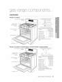
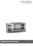
OVERVIEW
MODEL FX710BGS
Cooktop Burner Placement
Control Panel And Digital
Display
i
o ._
Heavy-Duty _..
continous cast
Grates
_
i({__'_ Flat surface
i_>Concaveline
_.5} i{-_
Convex surface
Cooktop Burners (under grates)
Burner Locations and Output Ratings
Cooktop Burner
Knobs
Oven
Racks
Location
Left-Front (LF)
Output Rating
(Natural Gas)
15,000 BTU
Left-Rear (LR)
Center (CTR)
9,500 BTU
9,500 BTU
Right-Rear (RR)
Right-Front (RF)
(3)
5,000 BTU
18,000 BTU
Warming Drawer
(with Full Extension Roller Guide
Rails)
Over] Door
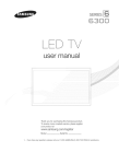
MODEL FX510BGS / NX583G0VBSR
Control Panel And Digital
Display
Heavy- Duty
continous cast
Grates
Cooktop Burner
Knobs
Over] Racks (2) --
/ NX583G0VBBB
/ NX583G0VBWW
Cooktop Burner Placement
O
O
Cooktop Burners (under grates)
Burner Locations and Output Ratings
Location
Output Rating
(Natural Gas)
15,000 BTU
Left-Front (LF1)
Left-Front (LF2)
12,000 BTU
9,500 BTU
Left-Rear (LR)
Center (CTR)
Right-Rear (RR)
Right-Front (RF)
9,500 BTU
5,000 BTU
17,000 BTU
1 MODEL FX510BGS
2 MODEL NX583GOVBSR /
NX583GOVBBB / NX583GOVBWW
Storage Drawer
Over] Door
gas range components
19
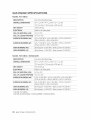
GAS RANGE SPECiFiCATiONS
MODEL FX710BGS
DESCRIPTION
Gas Free-StandingRange
OVERALL DIMENSIONS
29 ls/1_in (% x48 25/s2
in (H) x23 W_6in(D)
757 mm (W)x 1163 mm (H) x 602 mm (D)
NET WEIGHT
196 Ib (89 kg)
ELECTRICAL
Referto the rating label.
GAS. NG (NATURAL GAS)
5-13 in WC
GAS. LP (LIQUID PROPANE)
10-13 inWC
SURFACE BURNERS (NG)
(LF)-15,000 BTU /(LR)-9,800 BTU / (CTR)-9,800 BTU /
(RR)-5,000 BTU / (RF)-18,000 BTU
SURFACE BURNERS (LP)
(LF)-11,500 BTU / (LR)-7,800 BTU / (CTR)-7,800 BTU /
(RR)-4,000 BTU / (RF)-14,800 BTU
OVEN BURNERS (NG)
Broil (Upper)-13,500 BTU / Bake (Lower)-18,000 BTU
OVEN BURNERS (LP)
Broil (Upper)-11,500 BTU / Bake (Lower)-15,000 BTU
MODEL FX510BGS / NX583G0VB
DESCRIPTION
Gas Free-Standing Range
OVERALL DIMENSIONS
29 13/16
in (W)x 45 25/s2
in (H) x 23 11/1_
in (D)
757 mm (W) x 1163 mm (H) x 602 mm (D)
NET WEIGHT
187 Ib (85 kg)
ELECTRICAL
Referto the rating label.
GAS; NG (NATURAL GAs)
5-13 inWC
GASI LP (LIQUID PROPANE)
10-13 in WO
SURFACE BURNERS (NG)
(LF1)-18,000 BTU / (LF2)-12,000 BTU / (LR)-9,500 BTU /
(CTR)-9,800 BTU / (RR)-5,000 BTU / (RF)-I 7,000 BTU
SURFACE BURNERS (LP)
(LF)-10,000 BTU / (LR)-7,500 BTU/ (CTR)-7,500 BTU /
(RR)-4,000 BTU / (RF)-12,800 BTU
OVEN BURNERS (NG)Broil
OVEN BURNERS (LP)
(Upper)-13,500 BTU / Bake (Lower)-18,000 BTU
Broil (Upper)-11,500 BTU / Bake (Lower)-15,000 BTU
1 MODEL FX510BGS
2 MODEL NX583GOVBSR/ NX583GOVBBB/ NX583GOVBWW
20 gas range components
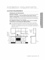
LOCATION
REQUIREMENTS
Clearances and dimensions
BEFORE YOU BEGIN to install this appliance, refer to the following information,
dimensions, and clearances. Do not locate the range where it may be
subject to strong drafts. Provide adequate clearances between the range and
adjacent combustible surfaces. These dimensions must be met for safe use of
the range. The location of the electrical outlet and gas piping may be adjusted to
meet the following dimensions and clearances.
For installation in Canada, a free-standing
range is not to be installed
closer than 4.7 in (12 era} from any adjacent surface.
_This
range has been designed to comply with the maximum allowable
....... wood cabinet temperature of 194°F (90 °C). Make sure the wall covering,
countertops, and cabinets around the range can withstand the heat (up to
194 °F [90 °C]) generated by the range. If not, discoloration, delamination, or
melting may occur.
r13 in (33 cm)
Overhead
Cabinet
o o
........................................
Side
Clearance
Above
Cooking
Surface
Wall
4 in
_
_
(10,2 cm)
]
_"
6 in
(15,2 ore)
to
36 in
0L_
30 in
o
QQ
Q
30 in (76.2 cm)
L_
t
Q@
o
o
24 in
0 in (Ocm)
(61 ore)
Lower
Cabinet
Below
Cooking Top
and a! Rear
and Sides of
o
Clearance
Depth
(91
1
18 in (45.7 cm)
Depth
!
0 in
(15,2 cm)
Rang e
installation requrements
21
Minimum
dimensions
w_,,GIf overhead cabinets are provided, a range hood should also be provided
that projects horizontally a minimum of 5 in (12.7 cm) beyond the front of
the cabinets. This will dissipate any heat buildup in the overhead cabinets
to prevent death, personal injury, and/or fire hazard. The ventilating hood
must be constructed of sheet metal not less then 0.0122" thick. Install
above the cooktop with a clearance of not less than 1/4" between the hood
and the underside of the combustible material or metal cabinet. The hood
must be at least as wide as the appliance and centered over the appliance.
Clearance between the cooking surface and the ventilation hood surface
must never be less than 24 inches.
Exception : Installation of a listed microwave oven or cooking appliance over
the cooktop shall conform to the installations packed with that appliance.
•
•
30-in (101.6-cm) minimum clearance between the top of the cooking
surface and the bottom of an unprotected wood or metal cabinet; or If no
30-in(101.6-cm) minimum clearance, 24-in (61-cm) minimum when the
bottom of the wood or metal cabinet is protected by not less than 0.25-in
(0.64-cm) flame-retardant millboard covered with not less than no. 28
MSG sheet steel, 0.015-in (0.038-cm) stainless steel, 0.024-in (0.061 cm) aluminum, or 0.020-in (0.051 -cm) copper.
18-in (45.7-cm) minimum between the countertop and the adjacent
cabinet bottom.
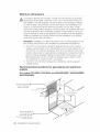
Recommended
outlets
locations
for gas piping
and electrical
(For models FX710BGS, FX510BGS, and NX583GOVBSR / NX583GOVBBB /
NX583GOVBWW}
Recommended area |
I
for 120 V electrical
outlet on rear wall,
2inx2in
(5.1 cm x 5,1
17 in x 9 in
,)
Gas Wall Area
(40,6 cm)
17 ihx2 in_
(43,2 cmx 5,1 cm)
_' _G_as..F:l?_o
r Area_.
Recommended
area
for through-the-wall
and through-the floor
connection of gas pipe stub
and shut-off valve,
22 installaton
requrements
GAS REQUIREMENTS
Provide adequate gas supply
This range is designed to operate at a pressure of 5 in (13 cm) of water
column on natural gas or 10 in (25 cm} of water column on LP gas
(propane or butane).
Make sure you are supplying your range with the type of gas for which it is
designed. Do not attempt to convert the appliance from the gas specified
in this manual to a different gas without consulting the gas supplier.
This range is convertible for use on natural or propane gas. If you decide to use
this range on LP gas, conversion must be made by a qualified LP installer before
attempting to operate the range.
For proper operation, the pressure of natural gas supplied to the regulator must
be between 5 in and 13 in (13 cm and 33 cm) of water column.
For LP gas, the pressure supplied must be between 10 in and 13 in (25 cm and
33 cm) of water column.
When checking for proper operation of the regulator, the inlet pressure must be
at least 1 in (2.5 cm) greater than the operating (manifold) pressure as given.
The pressure regulator located at the inlet of the range manifold must remain in
the supply line regardless of whether natural or LP gas is being used.
A flexible-metal appliance connector used to connect the range to the gas
supply line should have an I.D. of 0.5 in (1.3 cm) and be 5 ft (152 cm) in length
for ease of installation. In Canada, flexible connectors must be single-wall metal
connectors no longer than 6 ft (183 cm) in length.
Do not kink or damage the flexible metal tubing when moving the range.
installation requrements
23
SPECIAL GAS REQUIREMENTS
MASSACHUSETTS)
COMMONWEALTH
Z_Gas
OF MASSACHUSETTS
(GAS MODELS
SOLD IN
REQUIREMENTS:
leaks may occur in your system, creating a dangerous situation.
WARNING
-
Gas leaks may not be detected by smell alone.
Gas suppliers recommend you purchase and install a UL-approved
gas detector. Gas detector should be installed in accordance with the
manufacturers instructions.
Range must be installed by a qualified plumber or gas fitter by the State of
Massachusetts.
A T-handle manual gas valve MUST be installed in the gas supply line to your
range.
If a flexible gas connector is used to install your range, multiple flexible gas lines
must not be connected in series.
ELECTRICAL
REQUIREMENTS
Z_ To reduce the risk of fire, electric shock, or personal injury:
WARNING
All ranges
,,
Do not use an extension cord or adapter plug with this range.
This range must be properly grounded.
,,
Check with a qualified electrician if you are in doubt as to whether your range
is properly grounded.
,,
Do not modify the plug provided with your range--if it doesni-t fit the outlet,
have a proper outlet installed by a qualified electrician.
All wiring and grounding must be done in accordance with local codes or, in
the absence of local codes, with the National Electrical Code, ANSI/NFPA No.
70 - Latest Revision (for the U.S.) or the Canadian Electrical Code CSA C22.1
- Latest Revisions and local codes and ordinances.
,,
Wiring diagram is located on the back of the range. (Inside of the cover back
wire)
,,
This range is equipped with an electronic ignition system that will not operate
if plugged into an outlet that is not properly polarized.
24 installaton
requrements
Gas models
•
All gas models are equipped with a power cord with an equipment-grounding
conductor and a grounding plug.
•
A 120-Volt, 60-Hz, AC, approved electrical service with or 20-amp circuit
breaker or time-delay fuse is required for all U.S. and Canadian models.
•
Check for 3A-in (1.9-cm) UL-listed strain relief where the power cord comes
out of the range cabinet.
•
Do not reuse a power supply cord from an old range or other appliance.
•
The power cord electric supply wiring must be retained at the range cabinet
with a suitable UL-listed strain relief.
•
A time-delay fuse or circuit breaker is also recommended.
Grounding
•
All ranges must be grounded br personal safety.
•
All gas models have a power cord with an equipmentgrounding conductor
and a grounding plug.
•
The plug must be firml plugged into a three-prong outlet
that is properly installed and grounded in accordance with
all local codes and ordinances. In the event of a malfunction
or breakdown, grounding will increase the risk of electrical
shock by not providing a path tor the electric current.
connection
beforeuse,
•
Do not use a damaged power plug or loose wall outlet.
•
Do not use an extension cord or adapter with this appliance.
•
Do not, under any circumstances, cut, modify, remove, or otherwise defeat
the grounding (third) prong from the power cord. If the plug and the outlet
do not match or you have any doubt, have a qualified electrician install the
proper outlet.
The customer should have the wall receptacle and circle checked by a
qualified electrician to make sure the receptacle is properly grounded.
Ground Fault Circuit Interrupters(GFCIs) are not required ot recommended for
gas range receptacles.
•
NEVER connect ground wire to plastic plumbing lines, gas lines, or water
pipes.
Z_ Failure to follow these instructions can result in death, fire, or electrical
oAu,,o,
shock.
installation requrements
25
Usage situations where appliance
disconnected
frequently
power
cord will be
Do not use an adapter plug in these situations because disconnecting of the
power cord places undue strain on the adapter and leads to eventual failure
of the adapter ground terminal. Where a standard two-prong wall receptacle
is encountered, it is the personal responsibility and obligation of the customer
to have it replaced with a three-prong (grounding) receptacle by a qualified
electrician before using the appliance.
Additional
installation
requirements
for mobile
homes
The installation of appliances designed for mobile home installation must conform
with the Manufactured Home Construction and Safety Standard, Title 24 CFR,
Part 3280 (formerly the Federal Standard for Mobile Home Construction and
Safety, Title 24, HUD, Part 280) or, when such standard is not applicable, the
Standard for Manufactured Home Installations, latest edition (Manufactured
Home Sites, Communities and Set-Ups), ANSI A225.1, latest edition, or with
local codes. In Canada, mobile home installation must be in accordance with the
current CAN/CSA Z240/MH Mobile Home Installation Code.
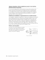
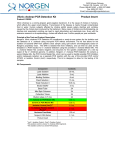
Power cord location
The power cord for this appliance is located
on the back of the range, near the bottom
right hand corner. The 59-in (150-cm) power
cord will come installed on the range and
taped to the back for shipping.
Power cord location
26 instal[aton
requrements
WHAT'S
iN THE BOX
Parts supplied
©
o
©
Surface burners and caps (5)
(Medel FX710BGS)
Oven racks (3)
Griddle
©
Surface burners and caps (5)
(Medel FX510BGS/NX583GOVB)
Surface burner grates (3)
Oven racks (2)
FX510BGS / NX583GOVB
FX710BGS
Anti-tip bracket kit
•
Make sure you have received all of the supplied parts shown above.
•
If your range was damaged during shipping or you do not have all of the
supplied parts, contact your local retailer.
Parts needed
®
Gas line
shut--off
valve
Flexible metal
appliance
connector Y2in (ID)
x 5 fl
Flare union
adapter 3A in or
_/2in (NPT) x _/2
in (ID)
®
Flare union
adapter Y2in
(NPr) x Y_in (ID)
135-degree
elbow
(optional)
Lag bolt
or Y2-in
(OD) sleeve
anchor
Tools needed
Flabblade
screwdriver
Phillips
screwdriver
Open-end or adjustable
wrench
Pipe wrench (2)
Nut driver
) '\
........ J
Pencil and
ruler
Level
Pipe joint compound
Utility knife
Soapy water
solution
tools and materials 27
INSTALLING
YOUR GAS RANGE
iMPORTANT: Please read the following instructions, as well as the Important Safety
Instructions section at the front of this manual, completely and carefully BEFORE
installing and/or operating the gas range. Improper installation, adjustment, service, or
maintenance can cause personal injury or property damage.
To order parts or accessories, contact your
local retailer or refer to the last page.
To ensure proper installation, we strongly
recommend that you hire a professional
installer.
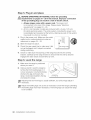
Step 1. Unpack
the range
Remove all packaging materials. Failure to remove packaging materials could
result in damage to the appliance.
Inventory all loose parts against the Parts supplied+ components listed on page 27.
Check for shipping damage and/or missing parts. Any damage and/or missing
parts should be reported to your local retailer.
Step 2. Connect
the range to gas supply
Shut off the main gas supply valve before disconnecting
the old range and
leave it off until the new hookup has been completed. Don't forget to relight
the pilot on other gas appliances when you turn the gas back on.
Because hard piping restricts movement of the range, the use of a CSA
International-certified flexible metal appliance connector is recommended unless
local codes require a hard-piped connection.
28 installaton
instructions
_lf
the information in this manual is not followed exactly, a fire or explosion
....... may result, causing death, personal injury, or property damage.
-
-
Do not store or use gasoline or other flammable vapors and liquids in the
vicinity of this or any other appliance.
WHAT TO DO IF YOU SMELL GAS:
,, DO NOT light a match, candle, or cigarette.
,, DO NOT try to light any appliance.
,, DO NOT touch any electrical switch.
DO NOT use any phone in your building.
Clear the room, building, or area of all occupants.
Immediately call your gas supplier from a neighbor's phone. Follow the
gas supplier's instructions.
,, If you cannot reach your gas supplier, call the fire department.
Installation and service must be performed by a qualified installer, service
agency, or gas supplier.
Never use an old connector when installing a new range. If the hard-piping
method is used, you must carefully align the pipe; the range cannot be moved
after the connection is made.
To prevent gas leaks, apply pipe-joint compound or wrap pipe-thread tape with
Teflon on all male (external) pipe threads.
1, Install a manual gas line shut-off valve in the gas line in an easily accessed
location outside of the range.
Make sure everyone operating the range knows where and how to shut off
the gas supply to the range.
2, Install male 0.5-in (1.3-mm) flare union adapter to the 0.5-in (1.3-mm) NPT
internal thread at the regulator inlet. Use a backup wrench on the regulator
fitting to avoid damage.
When installing the range from the front, remove the 90 o elbow for easier
installation.
3, Install male 0.5-in (1.3-mm) or 0.75-in (1.9-mm) flare union adapter to the
NPT internal thread of the manual shut-off valve, taking care to back up the
shut-off valve to keep it from turning.
4, Connect flexible metal appliance connector to the adapter on the range.
Position range to permit connection at the shut-off valve.
5, When all connections have been made, make sure all range controls are
in the off position and turn on the main gas supply valve. Use a liquid leak
detector at all joints and connections to check for leaks in the system.
ADo
not use a flame to check for gas leaks to prevent death, personal injury,
....... explosion, and/or fire hazard.
When using test pressures greater than 1/2 psig to pressure-test the gas supply
system of the residence, disconnect the range and individual shut-off valve from
the gas supply piping. When using test pressures of 1/2 psig or less to test
the gas supply system, simply isolate the range from the gas supply system by
closing the individual shut-off valve.
instalation
instructions 29
Flexible connector
hookup
Installer: Inform the consumer of the location of the gas shut-off valve.
lf your area requires a rigid pipe
hookup, contact a qualified
installer, service agency, or gas
supplier.
GasShut--Off
Valve
0,5-in or 0,75-in Gas
Adapter
gas shut-off valve should
% The
be installed in an accessible
location in the gas piping,
external to the appliance, for the
purpose of turning on or shutting
off the gas to the appliance.
Step 3. Convert
Flex Connector
(64t max.)
Pipe
Thbing Line to
Oven Burner
Control Valve
r;Jbing Line
to Cooktop
Control
Manifold h
Pressure r_
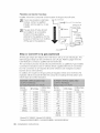
to Ip gas (optional)
All new gas ranges are shipped from the factory set up to use natural gas. Any
Samsung gas range can be converted to use LP gas. Refer to page 78 in the
User Manual to contact a qualified service technician.
The conversion process should only be performed by a qualified LP gas installer.
Conversion instructions and LP orifices will be supplied with the LP conversion
kit. The conversion to LP requires all burner orifices to be changed (5 surface
burners and 2 oven burners).
In addition, the nozzle on the gas pressure regulator needs to be reversed. All
replaced orifices must be left with the consumer, including the instructions and
retrofit sizes and orifice indication.
Burner
Location
RF_
RF2.S
LF_
LF2.3
RR
LR
CTR
BAKE
BROIL
BTU Rate
14,500
12,500
11,500
10,000
4,000
7,500
7,500
15,000
11,500
Orifice Size
[mm]
1.05/0.52
1.06
1.04
0.98
0.62
0.83
0.83
1.15
1.02
Burner
Location
RF1
RF2
RFs
LF_,2
LFs
RR1,2
RR3
LR
CTR
BAKE
BROIL
BTU Rate
18,000
17,000
17,000
15,000
12,000
5,000
5,000
9,500
9,500
18,000
13,500
' Model FX710BGS 2Model FX510BGS
3 Model NX583G0VBSR / NX583G0VBBB / NX583G0VBWW
30 installaton
instructions
Orifice Size
[mm]
1.80/0.73
1.90
1.92
1.78
1.60
1.00
1.01
1.40
1.38
1.90
1.64
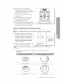
Step 4. Install the anti-tip
device
/_To
reduce the risk of tipping, the appliance must be secured by properly
....... installing the anti-tip device packed with the appliance.
•
All ranges can tip, resulting in personal injury.
Tipping ranges can cause burns from spills, personal injury, and/or death.
To prevent accidental tipping, install and check the anti-tip bracket
following the instructions and template supplied with the bracket.
An anti-tip bracket and screws,
installation instructions, and template
are shipped with every range (PN
DG94-00670A). The instructions include
information necessary to complete the
installation of the anti-tip bracket. Read
and follow the instructions on the sheet
and use the template for anti-tip bracket
installation. If not properly installed, the
J_
range could be tipped by you or a child
standing, sitting, or leaning on an open oven door.
To install an anti-tip bracket, release and extend the leveling leg to a
minimum clearance of 21/32 in (16.5 mm) between the range bottom and
the floor.
To check if the bracket is installed and engaged properly, remove the warming
drawer or storage drawer and look underneath the range to see that the leveling
leg is engaged in the bracket. Carefully tip the range forward. The bracket should
stop the range within 4 inches (10.2 cm) of tipping. If it does not, the bracket
must be reinstalled.
If the range is pulled from the wall for any reason, always repeat this procedure
to verify the range is properly secured by the anti-tip bracket. Never completely
remove the leveling legs or the range will not be secured to the anti-tip device
properly.
nstaIIaton
instructions 31
Step 5. Plug in and place
/_k BEFORE OPERATING OR TESTING, follow the grounding
.......
"'" requirements
on pages 24 ~ 26 in this manual improper connection
of the grounding plug can result in a risk of electric shock.
•
All gas ranges come with a power cord. The power cord
is connected to the rear of the range. Please review "Electrical
requirements" on pages 24 - 26.
All U.S. and Canadian models are produced with a 3-wire, 120-volt,
60-Hertz electrical system. The entire system, including the power cord,
is preinstalled and prewired at the factory. Altering any part of this system
may result in a short or overload.
•
1. Plug in the power cord. Make sure the outlet
meets local or national electrical codes as
referenced on pages 24 - 26.
I
I_
2. Slide the range into place.
3. Check the gas supply line to make sure it did
not get damaged and it stayed connected
during positioning.
_ .
@
.......
_o
4. Check to make sure the back leg of the range has slid into the anti-tip
bracket. Carefully tip the range forward to ensure that the anti-tip bracket
engages the back brace and prevents tip-over.
Step
1.
6. Level
the range
Make sure the range is positioned
where you want it.
2. Using a wrench, level the range by
turning the front leveling legs in or
out as necessary. Counterclockwise
shortens the leg and lowers the
range. Clockwise lengthens the leg
and raises the range.
Leveling leg
[_
djusting the two front legs is usually sufficient, but all four legs adjust if
necessary.
[_
Adjust the leveling legs only as far as necessary to level the range. Extending
the leveling legs more than necessary or removing legs can cause the range
to be unstable.
32 nstatation
instructions
3, If range is next to or between
cabinets, make sure the cooktop
(without the surface burner grates) is
level with the countertops.
4, Position an oven rack in the center
rack position.
@@
@
@@
5, Check the level of the range with
a carpenter level using the two
positions shown at right.
8, After the range becomes level, slide
the range away from the wall so that
the anti-tip bracket can be installed.
Step 7. Assemble
ADo
not operate
the surface
the surface burners
burners
without all burner parts in place.
CAUTION
1. Position surface burner heads on
top of the surface burner manifolds
as shown at right. The electrodes
will fit into the slot in the bottom of
the heads. Make sure the surface
burner heads are flat and parallel
with the cooktop.
2.
Place the matching size caps on top
of each surface burner head.
Model FX710BGS
©
o
Model FX510BGS
/ NX583GOVB
Precise simmer burner(RR)cap should be set on top of the Right-rear
burner.
Check the cap type before placing the cap on the Precise simmer
burner(RR).
C0nvex surface ......
Flat SurfaCe
0
Convex line
Concave line
nstaIIaton
instructions 33
3,
Place the left, center, and right
surface burner grates on the
cooktop. The edges of the grates
should match up with the edges of
the cooktop.
Step 8. Check the ignition
burners
of surface
burners
and oven
Check the operation of all cooktop and oven burners after the range has been
installed and assembled, gas supply lines have been carefully checked for leaks,
and electrical power cord has been plugged in.
All surface and oven burners have electronic ignition.
To turn
on a surface
burner:
1o Push in and turn the control knob
for that surface burner to the LITE
position. The "clicking" sound
indicates the electronic ignition
system is operating properly. The
burner will light in about 4 seconds,
after the air has been purged from
the supply line.
........
: _lmm_-
......
_..._.:
_111_
2. After the burner lights, turn the
control knob to the desired setting.
The "clicking" sound will stop and the flame height will change from Max. to
Min. during turning the control knob.
3. Repeat steps 1 and 2 to check the operation of each surface burner
insuccession.
[_
lace food in the oven after preheating if the recipe calls for it. Preheating is
important for good baking results. After the oven has reached the desired
cooking temperature, it will beep 6 times.
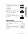
To start the bake
burners:
1=
Press the BAKE pad. The oven will beep every time a
pad is pressed.
The default temperature 350 ° and the Start indicator
will blink on the display. If the default temperature is the
desired cooking temperature, skip to step 2.
2=
Press the number pads to change the temperature
setting to the desired temperature setting. The selected
cooking temperature and the Start indicator will blink on
the display.
34 nstatation
instructions
3.
Press the START pad.
The display will show a blinking *, along with 150 o, Bake,
and the bake element icon, until the oven reaches that
temperature; then the display will just show the actual
oven temperature.
The oven will automatically light after 30-90 seconds and
start preheating.
When the oven reaches the desired baking temperature,
it will beep 6 times.
4. Press the CLEAR/OFF pad to shut off the oven.
The display will show the time of day.
The oven burners require electrical power to operate.
They cannot be lit manually with a match, so the oven
cannot be used during power outages.
To start
the broil burners:
To check ignition of the broil burner, touch the Broil Hi/Lo
Pad and then the start pad. After 30-90 seconds, the broil
burner will ignite.
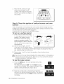
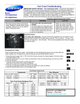
Checking
the flame
quality:
All combustion flames need to be visually checked to determine their flame
quality.
1, Soft blue flames--Normal
2.
for natural gas operation.
Yellow tips on outer cones--Normal
operation.
3, Yellow flames--Abnormal
for service.
for LP gas
for any gas operation; call
lf burner flame looks like 3, the range should not be
used until it is serviced. Call for service. Normal burner
flames shall look like 1 or 2, dependin on the gas type
you use.
nstalIaton
instructions 35
Step 9. Final installation
checklist
You have just completed installing your range. Make sure all controls are in the off
position and the flow of ventilation air to the range is unobstructed. The following
is a checklist to confirm your range is safely installed and ready for operation.
Gas line has been properly connected to the range.
The gas has been turned on. All connections have been
checked for leaks.
[
Range is plugged into the properly grounded electrical
receptacle.
Approved anti-tip bracket is properly installed and engaged with the range.
Range is leveled and is firmly sitting on a solid,
level floor.
Gas surface burners have been properly
assembled.
All burners have been tested for proper
operation.
FOR INSTALLER ONLY--Check and/or adjust
the broil and oven burner flames as described on
page 37 in this manual.
36 nstatation
instructions
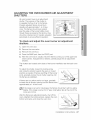
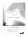
ADJUSTING
SHUTTERS
THE OVEN BURNER AmR ADJUSTMENT
All oven burners have an air adjustment
shutter. The purpose of the shutter is
to regulate the flow of air to the flames.
Properly adjusted flames should burn
steadily with approximately 1-in of blue
cone. The flames should never extend
past the edge of the burner baffles. Even
though these are preset at the factory, they
should be checked and, if needed, adjusted
periodically to ensure efficient operation.
To check
shutters:
and adjust
the oven burner
air adjustment
1. Open the oven door.
2. Remove the oven racks.
3. Remove the oven floor.
4. Press the BAKE pad, then the START pad.
5. After the oven has lit, visually check the flames coming out of the upper and
lower burners. If adjustment is needed, carefully adjust the air adjustment
shutters.
The shutters are located at the base of the burner manifolds near the back oven
wall.
To adjust the shutter, loosen the locking screw
and rotate the shutter towards the open or closed
position as needed. If flames are lifting off the burner
ports, gradually reduce the air shutter opening until
the flames are stabilized.
If flames are too yellow and/or too large, gradually
increase the air shutter opening until the flames have
approximately a 1-in blue cone.
lf the range is set up for natural gas, the flames should burn with no yellow
tipping. If the range is set up for LP gas, small yellow tips at the end of the
cones are normal.
After the flames are adjusted properly, shut off the
oven, retighten the locking screws, replace the oven
bottom and racks, and close the oven door.
Locking screw
nstaIIaton
instructions
37
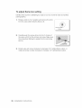
To adjust
flame low setting
Identify which burner is exhibiting too high or too low of simmer rate via manifold
panel graphics.
1, Rotate a knob to "LO" position and remove the knob
from the valve shaft while the flame is lit.
2_
Carefully push the screw driver into the C chanel of
the valve, until it his the simmer set screw. Make sure
the screwdriver flathead is seated into the set screw
groove.
3. Rotate valve set screw clockwise to decrease "LO" setting flame output, or
rotate set screw counter clockwise to increase "LO" setting flame output.
38 nstatation
instructions
Scan the QR code * or visit
www.samsung.com/spsn
to view our helpful
How-to Videos and Live Shows
*Requires reader to be installed
Scan this with your
on your smartphone
smartphone
QUESTIONS
ORCOMMENTS
CANADA
1-800-SAMSUNG
MEXICO
01-800-SAMSUNG
(726-7864)
www>samsung>com/ca
www,samsung,com/ca
fr (French)
(726-7864)
www,samsung,com
U.S.A
1-800-SAMSUNG
(726-7864)
Code No.: DG68-00357A-01