1
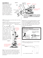
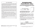
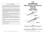
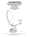
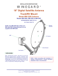
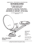
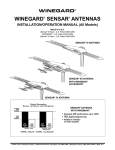
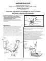
WINEGARD
®
Digital Elevation Sensor
Electronic Calibrated Model for RM and RD models
Models DM-4000/2000
U.S. Patent 5,945,945
THIS UNIT HAS BEEN CALIBRATED AT THE FACTORY.
No further calibration is necessary.
BEFORE YOU BEGIN, take a few minutes to look at
Figure 1. Be sure you have received all parts.
Contact Winegard Company for help if you have
questions concerning this product.
Technical Service hours are 7:00 a.m. to 4:00 p.m.,
Monday through Friday, Central Time. Call toll-free at
1-800-788-4417.
Sensor w/Cable
*#10-32 Hex Nut (2)
*1/4-20 x 2" Hex
Bolt )2)
*#10-32 x 1/2"
Screw (2)
*1/4" Flat Washer (2)
*Mounting Plate
Figure 1
RM MODELS
STEP 1: To install sensor on your RM model, remove
dish from backup frame. Place sensor inside backup
frame, Figure 4. Cable must exit from bottom of
sensor. Route under pins, Figure 4. To place case
correctly, mounting screws must be completely in slots.
Fasten sensor case to frame, being careful not to
overtighten. Loosely secure Sensor cable to coax with
wire ties. Pivot feed arm toward backup frame, making
sure sensor cable is not preventing movement. When
cable is properly positioned, finish tightening wire ties.
Figure 2
*included in hardware bag #2762472
STEP 2: Using cable ties (provided), attach sensor cable
to coax cable, Figure 3.
NOTE: Some RV manufacturers prewire the coach with
cable for the digital elevation sensor. These wires are
found at the appropriately marked spot on the roof.
If not prewired, run wires from sensor through opening
(normally the same entrance as coax) into the vehicle to
the area where you are installing the wall plate
display unit. It is recommended the display unit be
mounted so you can read the elevation numbers while
moving the antenna to the correct angle.
Figure 3
Backup
Frame
Sensor
Case
Sensor
Cable
Sensor cable
Feed arm
Pivot feed arm
toward backup
frame.
Coax cable
Sensor cable
Winegard Company • 3000 Kirkwood St. • Burlington, Iowa
1
52601-2000 © 2001 Winegard Company 2451568
RD MODELS
STEP 1: Positioning antenna
to a near vertical angle will
make installation easier.
Assemble mounting plate
against fixed feed arm, Figure
4. Remove existing 1/4” nuts,
bolts and washers. Using new
hex bolts and nuts and washers
you just removed, assemble
parts as shown. Align the plate
parallel to elevating tube,
Figure 4, and tighten hardware.
Figure 4
#10-32
Hex Nut
(2) 1/4" Flat
Washer, for
RD-4610 only
Fixed Feed
Arm
Elevating Tube
Mounting
Plate
Sensor
1/4-20 x 2" Hex Bolt
#10-32 x 1/2" Screw
1/4" Flat Washer
1/4" Flat
Washer
1/4-20
Hex Nut
CAUTION: Sensor MUST be mounted on side that
coax cable is attached to gear housing. Mounting
differently than shown WILL CAUSE IMPROPER
OPERATION.
STEP 2: Using cable ties (provided), attach sensor cable
to coax cable, Figure 5.
NOTE: Some RV manufacturers prewire the coach with
cable for the digital elevation sensor. These wires are
found at the appropriately
marked spot on the
roof.
If not prewired, run
wires from sensor through
Use a level to
opening (normally the
ensure antenna
is plumb (90o)
same entrance as coax)
into the vehicle to the
Antenna
location where you
are installing the wall
plate display unit. It is
recommended the display
unit be mounted so you
can read the elevation
numbers while moving the
antenna to the correct angle.
Elevating Tube
With antenna plumb, readout
should be 24°.
Step 4: Figure 6 shows the different methods of connecting wires at roof level. Method will depend on model.
Wire colors MUST MATCH (red to red, black to black,
green to green). NOTE: Some prewire systems, or older
models, used 4 wires. Ignore the white wire when connecting model DM-4000/2000.
Figure 6
Supplied with the DM-2000 only.
NOTE: This terminal is weatherproof and can be left outside on
the roof as LONG AS IT IS SECURED PROPERLY to prevent
whipping in the wind.
3M UR Terminal
Slide wires all
the way in.
DO NOT strip
wires, terminal
is self stripping.
Squeeze pliers until red
plunger is flush with rest
of terminal.
Pliers not supplied
Figure 5
STEP 7: If using SM-1000 surface mount box (Figure
7), feed cable through hole in box.
Use cable ties provided to
secure sensor cable to
coax downlead.
Sensor
mounting
plates
Step 3: Two persons will be required for this step, one
inside the vehicle and one outside. Using the interior
elevating crank, raise antenna to vertical (plumb) position. Place a level across face of antenna as shown and,
using interior crank, adjust to a perfect plumb. BE
ACCURATE!
Figure 7
SM-1000 Surface Mount Box
(optional).
#6 x 1/2” Phillips Screw (optional).
2
Figure 8
CAUTION:
If using +12 VDC, it must be FILTERED!
If using non-filtered +12 VDC, the product will be
damaged and Warranty voided.
Cable and plug
from roof
sensor unit;
plugs into
sensor readout
cable.
STEP 8: Connect wires coming from sensor on roof to
wall plate display in vehicle, Figure 8. It is important to
properly connect the wires at the roof and the wall plate.
(Plug will click when inserted properly.) The system is
designed to use a 9 volt battery OR +12 VDC from
vehicle. Do not use both! IMPROPER WIRING WILL
CAUSE DAMAGE TO THE PRODUCT.
Cut here for prewire
applications
Sensor-to-readout
cable
Readout assembly
Power cable harness
Red=Positive
Black=Negative
STEP 9: Pressing the button when the antenna is in a
vertical position should display 24 (can be plus [+] or
minus [-] 1 degree). Display will automatically turn off
after 1 minute.
(This cable not used with
9 V battery)
STEP 10: Check connectors and cable entry points. Be
sure these areas are properly sealed to prevent water
damage to the system and property.
ERROR CODES on display
LL ............... Low Limit
(antenna too low)
HL .............. High Limit
(antenna past range of readout)
LO ............ Low Battery
ER .... Connection Fault
(check wiring & connections)
OPERATING INSTRUCTIONS
Special Notes: When you have found the satellite signal,
adjust the antenna up/down and right/left for the strongest signal your receiver displays. Due to variation in
receivers and installation methods, you may find the
elevation numbers after peaking on strongest signal no
longer match what the receiver display recommended.
This is normal. The elevation sensor should always get
you close enough to pick up a signal to peak on. If
display turns off while you’re searching, just push button
for another minute of operation. With a little practice,
most users find the signal in 30 to 50 seconds.
STEP 1: Using satellite receiver, find correct elevation
for your location. See the receiver manual for details of
setup information.
STEP 2: Press button on Winegard digital display wall
plate. If antenna is in travel position, the display will
show HL for High Limit (RD models), LL for Low Limit
(RM models).
STEP 3: Crank elevation handle to raise antenna. Stop
when readout displays correct elevation for your
location.(Found on receiver setup menu.)
STEP 4: Rotate antenna VERY SLOWLY until correct
satellite signal is acquired. NOTE: Rotate 3° and stop.
DO NOT rotate continuously even if your are rotating
slowly. If the elevation angle has changed, it could be due
to the following —
• Vehicle is not parked level.
• Antenna system mounted on slightly sloped roof. If
this is the reason, after you have rotated the antenna
to the appproximate correct compass direction, adjust
to correct elevation and continue search.
Replacement Parts
For replacement parts, contact Winegard Company.
Customer Service hours are 7:00 a.m. to 5:00 p.m.,
Monday - Friday, Central Time. Call toll-free
1-800-288-8094. Credit card only, $5.00 minimum order.
Refer to Figure 1 on page 1 of this instruction sheet for
part numbers.
3
Printed in U.S.A. Winegard Company • 3000 Kirkwood St. • Burlington, Iowa 52601-2000 © 2001 Winegard Company 2451568
4