1
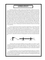
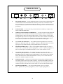
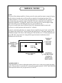
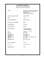
OWNER'S MANUAL
LANGEVIN
ALL-DISCRETE PULTEC
EQP1-A TYPE EQUALIZER
MANLEY
LABORATORIES, INC.
MANUFACTURED BY
MANLEY LABORATORIES, INC.
13880 MAGNOLIA AVE.
CHINO, CA. 91710
TEL: (909) 627-4256
FAX: (909)628-2482
email: [email protected]
http://www.manleylabs.com
CONTENTS
SECTION
PAGE
INTRODUCTION
3
MAINS CONNECTIONS
4
OPERATION
5
CONNECTIONS
6
FRONT PANEL
7
REAR PANEL
8
SERVICE
9
SPECIFICATIONS
10
WARRANTY
11
WARRANTY REGISTRATION
12
APPENDIX "1"
WIRING YOUR OWN CABLES
INTRODUCTION
THANK YOU!...
for choosing the Langevin All-discrete Pultec Type Equalizer. The Langevin Pultec Equalizer utilizes the original
WESTERN ELECTRIC passive-equalization circuit found in the long-out-of-production and justifiably famous
PULTECS. It is also the exact EQ section found in our MANLEY Enhanced Pultec EQ, the difference being that
the Manley unit uses and all-tube make up gain amplifier while the Langevin employs an all discrete make up gain
amplifying circuit. Our versions of this classic EQ incorporates superior modern components with our proven lineamp superiority for absolute sonic cleanliness... Conductive plastic potentiometers and sealed gold-contact
switches, polystyrene and rolled film and foil capacitors, precision 1% metal-film resistors (no cheap carbon
resistors here!), solid, rugged, servicable, yet handsome metal and chassis work, combine with a cleverly regulated
power supply and state-of-the-art solid state circuitry to bring the PULTEC into the nineties and beyond....
You have purchased our Rev. B version which now features all-discrete balanced inputs and outputs as well as
additional unbalanced inputs and outputs. All inputs and outputs are protected against shorted terminations. The
headroom and noise floor of this unit have been greatly improved over our early units.
Please take a few moments to read through this manual carefully as it contains information essential to proper
operation of this unit.
Thank you again, and please enjoy!
GENERAL NOTES
LOCATION & VENTILATION
The Langevin Pultec Type EQ must be installed in a stable location with ample ventilation. It is recommended,
if this unit is rack mounted, that you allow enough clearance on the top and bottom of the unit such that constant
movement of air can flow through the ventilation holes.
WATER & MOISTURE
As with any electrical equipment, this equipment should not be used near water or moisture. If liquid enters the
unit, it should be returned to your dealer for servicing.
SERVICING
The user should not attempt to service this unit beyond that described in the owner's manual. Refer all servicing
to Manley Laboratories.
WARNING!
!
TO PREVENT THE RISK OF ELECTRIC SHOCK
DO NOT OPEN THE CABINET
REFER SERVICING TO
QUALIFIED PERSONNEL
3
MAINS CONNECTIONS
Your Pultec has been factory set to the correct mains voltage for your country. The voltage setting
is marked on the serial badge, located on the rear panel. Check that this complies with your local
supply.
Export units for certain markets have a moulded mains plug fitted to comply with local requirements.
If your unit does not have a plug fitted the coloured wires should be connected to the appropriate plug
terminals in accordance with the following code.
GREEN/YELLOW
BLUE
BROWN
EARTH
NEUTRAL
LIVE
terminal
terminal
terminal
As the colours of the wires in the mains lead may not correspond with the coloured marking
identifying the terminals in your plug proceed as follows;
The wire which is coloured GREEN/YELLOW must be connected to the terminal in the plug which
is marked by the letter E or by the safety earth symbol or coloured GREEN or GREEN and
YELLOW.
The wire which is coloured BLUE must be connected to the terminal in the plug which is marked
by the letter N or coloured BLACK.
The wire which is coloured BROWN must be connected to the terminal in the plug which is marked
by the letter L or coloured RED.
DO NOT CONNECT/SWITCH ON THE MAINS SUPPLY UNTIL ALL OTHER
CONNECTIONS HAVE BEEN MADE.
4
OPERATION
The Langevin EQP1-A is another variation of the Pultec EQP1-A. Manley Labs is the only
company today with permission from Eugene Shenk (founder of Pulse Technologies) to use the original
Western Electric passive EQ circuitry that Pultec licensed and were given Eugene's personal blessing
in the endeavor. We have improved on the circuit by increasing the number of frequencies and by using
an all discrete solid state 10 dB make-up gain amplifier / line driver. We also use much better quality
parts and manufacturing techniques than was available back when Pultec was in production. The Pultec
EQs are one of the few pieces of professional audio equipment that has stood the test of time and is
usually one of the three top choices of engineers when asked to name their favorite EQs. It is because
the circuit has a musical transparent quality often missing in modern designs. We believe the reason for
this is that the EQ has no active circuitry and is based only on a few capacitors and inductors along with
a few resistors and pots. Hard to beat sound-wise. There is one disadvantage to vintage passive EQs.
The type and range of controls is less than what may be found in most modern EQs. While parametric
EQs may be more versatile for removing some types of problems, they may be the wrong choice for
a general every-day "tone" controls. The old Pultec EQs are famous for the drums, bass and whatever
could use some extra "cruch" with that big low bottom end, but the Manley/Langevin are clean enough
to use on anything.
The most common question from those only familiar with parametrics is "Why both a boost and
cut for the lows- couldn't you just have a single control with cut & boost". Three reasons - In the circuit,
the controls are in different places and each has its own associated parts. #2 - we did not design this
circuit - we are not about to change the basic design of something that works this well. #3 - Almost every
Pultec user finds the combination of both boosting and cutting gives not only the best results but results
that are almost impossible with parametrics. The curves of the boost and cut are not symetrical and don't
cancel each other out as might be expected. Instead some of the lower mid is cut when both controls are
used. In practice, usually more boost than cut is dialed up and the result tends to look approximately like
this:
Flat
20 Hz
1000 Hz
20 kHz
The slopes of the low boost and cut and high cut sections are 6 dB per octave which is very gentle
and smooth. The slopes become slightly steeper when the combination of boost and cut is used. Few
console EQs are this gentle- not even on million dollar desks. The section marked "high boost" could
be considered mid to high boost with the frequencies ranging from 1.5 kHz to 16 kHz. There is a bandwith
control that is roughly equivalent to "Q" on parametric EQs but the range is less and tends to be both more
subtle and musical.
One other bit of Pultec trivia - the circuit was designed to help make telephone lines sound better
- even acceptable for music (Western Electric remember!). That is why the EQ arrangement is the way
it is. It was designed to "fix" less than perfect transducers and lines. It is not surprising to us that this circuit
helps low cost mics and digital recordings. Contrary to many claims - too much gear today still sounds
just a bit better than telephone quality.
5
CONNECTIONS
The Langevin products are very easy to connect in most studio situations. There are both
XLR balanced inputs and outputs as well as 1/4 inch jacks for unbalanced inputs and outputs. Please
read this section because there is some special considerations and notes.
The XLR Inputs and Outputs are transformerless. The Pin Out is as follows:
PIN 1 = GROUND
PIN 2 = HOT (positive going phase)
PIN 3 = LOW (negative going phase)
The inputs are designed to be used with the professional standard of +4 dBm nominal levels
and will handle +26 dBm peaks. The input impedance is 20 Kohms. There is a 3 position PHASE
SWITCH (polarity) on the back panel. The normal setting is 0˚. Changing it to 180˚ reverses the
phase. The middle position is DIR IN and is meant for the 1/4" input and disconnects the XLR. You
could lose signal here.
The XLR outputs must only be used to drive balanced inputs. This excludes many project
console insert points where a 1/4" stereo jack shares both send and return functions. Use the
unbalanced output instead. The signal on pin 3 is derived from pin 2. If pin 3 is shorted to ground
(typical unbalanced hook-up) then a 6 dB loss occurs. If pin 2 is shorted to ground (typical miswired studio) then all signal is lost except for some low level distortion. If you have either of these
symtoms using the balanced output, you should just try the unbalanced output. A 6 dB loss could
also be caused by a bad cable that is not connecting either pin 2 or 3 ("open") all the way back to the
console.
The 1/4 inch jacks are meant to be used with unbalanced or "single-ended" sends and
returns. The Phase Switch should be set to DIR IN which disconnects the XLR input. Note that the
unbalanced input is always on and that you should not use both inputs and "select" with this switch.
The 1/4 inch unbalanced output is designed to mate only with mono (tip-sleeve) plugs. If
one uses stereo (tip - ring - sleeve) plugs then most likely the output will be down 6 dB. The only
way around this is to connect the sleeve to the ring - if you must use a stereo plug.
The UNBALANCED Pin Out is as follows:
SLEEVE = GROUND
TIP = SIGNAL
There are also two ground terminals on the back panel. CIRCUIT GROUND and CHASSIS
GROUND. Normally these are connected together with a a small piece of metal called a ground
strap. These terminals are used to find and fix hum problems. CIRCUIT GROUND is the ground of
the audio electronics. Chassis ground is like the third pin mains ground but also includes the chassis
that is often grounded in a rack. If you are hunting hum problems first try separating these terminals.
You can also try running a wire between the console to either of the terminals. You might also try
cutting the shields at the cables to the unit to break ground loops. The general idea is that every piece
of gear should have one and only one ground point - all these extra grounds can cause a ground loop
and hum is the usual result. Another possible cause of hum is that some gear radiates a strong hum
field. You might try moving it or the Langevin away from each other. Don't panic - experiment a bit.
6
FRONT PANEL
IN
BOOST
SELECT
CUT
BANDWIDTH
D
E
SELECT BOOST
SELECT CUT
POWER
BYPASS
A
B
C
LOW FREQUENCY
SECTION
F
G
HIGH FREQUENCY BOOST
SECTION
H
I
J
K
HIGH FREQ. CUT
SECTION
A
IN / BYPASS - This switch in BYPASS mode bypasses the EQ section while the amplifier
remains in circuit.
B
L.F. BOOST - Provides continuously variable BOOST from 0dB to +12dB to the low
frequency selected by control C. This is not symetrical with the CUT control so that
combinations of boost and cut do not simply cancel each other but give a different sound
unobtainable with other EQs.
C
LOW FREQUENCY SELECTOR - Determines frequency at which maximum L.F. BOOST
or CUT occurs.
D
L.F. CUT - Provides continuously variable CUT from 0dB to -15dB to the low frequency
selected by control C.
E
BANDWIDTH - This continuously variable control affects the width of the HIGH
FREQUENCY BOOST curves. Use minimum setting for a smaller range or area of high
frequencies affected by the H.F. BOOST control or maximum setting for a larger, broader
range of frequencies affected by the H.F. BOOST control. Similar to "Q" in parametric EQs.
F
H.F. BOOST - Provides Continuously varaible BOOST from 0 to +17dB to the high
frequency selected by control G.
G
HIGH FREQUENCY BOOST SELECT - Selects at which frequency maximum operation of
the H.F. BOOST section occurs. The frequencies are marked in KiloHertz.
H
HIGH FREQUENCY CUT - Provides continuously variable CUT from 0 to -15dB starting
(-3 dB) at the frequency chosen by control I. This is a shelf EQ rather than a low pass filter so
that the user has control of the depth and frequency.
I
HIGH FREQUENCY CUT SELECT - Selects at which frequency the H.F. CUT control
occurs.
J
LED - Illuminates when the power is on.
K
POWER ON / OFF - This switch engages UP turns the power ON; engaged DOWN
switches the power OFF.
7
REAR PANEL
A
B
C
D
E
F
G
H
A
IEC MAINS SOCKET - Accepts standard 50/60 Hz AC mains voltage. The third pin earth
is tied to chassis in this unit. Inside the unit (if the top is removed) is a switch next to the
power transformer for selecting mains voltage for either 110 or 220 VAC. This is factory set
for your country but if you do a lot of international recording it is nice to know this unit can
go with you.
B
FUSE HOLDER - To remove the fuse, push and turn the fuse holder cap. Replace only
with a 1 AMP SLO-BLO FUSE.
C
CIRCUIT, CHASSIS GROUND TERMINALS - Use these terminals to help find and fix
hum problems. These terminals are normally connected together to link circuit and chassis
grounds which ties audio to the mains ground & chassis. Loosen the posts so that the little
metal ground strap can swivel to separate audio from chassis. This is similar to "breaking off
the third pin AC mains ground but includes the chassis (normally grounded by the rack) as
well. You can also connect a wire between the console and either of these posts.
E
1/4" UNBALANCED OUTPUT - This UNBALANCED output MUST be used with a
MONO 1/4" phone jack wired: TIP = SIGNAL, SLEEVE = GROUND. Do not use a stereo
(tip-ring-sleeve) jack unless the ring is also grounded to the sleeve in the jack.
F
XLR BALANCED OUTPUT - This is a low impedance balanced output. Pin out is as
follows: PIN 1 - ground, PIN 2- positive going phase (+), PIN 3 - negative going phase (-).
Do not use this output to feed unbalanced inputs or levels will be 6 dB low or worse.
G
1/4" UNBALANCED INPUT - This UNBALANCED intput can be used with a
MONO 1/4" phone jack wired: TIP = SIGNAL, SLEEVE = GROUND. Use the PHASE
REVERSE switch in the middle position marked "DIR IN" when using this jack so that the
XLR is disconnected The UNBALANCED INPUT is always "on" so connect either the
balanced or unbalanced inputs but not both.
H
PHASE REVERSE - Switched in the UP position is normal (retains the balanced XLR
input signal in phase with respect to PIN 2 & PIN 3). Switched in the DOWN position will
reverse the phase(polarity) of the balanced XLR input signal. The middle position marked
"DIR IN" disconnects the XLR entirely and is meant to be used with the unbalanced input.
I
XLR BALANCED INPUT - All- discrete balanced input. Pin out is as follows:
PIN 1 - ground, PIN 2- positive going phase (+), PIN 3 - negative going phase (-).
8
SERVICE NOTES
GAIN
The gain of the makeup amplifier is factory preset for unity gain from input to output in bypass
mode (which is also the same as all boost & cut controls set at minimum positions, fully
counter-clockwise). If for some reason your EQ needs to be re-trimmed for unity gain or you
need other than unity gain the trimmer is labelled VR1 and it adjusts the basic gain of the
output line amplifiers. To adjust this, simply remove the top cover by unscrewing the single
rear center fixing screw and sliding the top cover out towards the rear.
The pot is located in the center left third of the PCB. Adjustment should be made with
reference to a signal generator and external AC voltmeter.
It may be worth noting that there are separate discrete amplifiers for pins 2 and 3 on the XLR.
The input for the amp for pin 3 is derived from the signal on pin 2. The signal feeding the 1/4"
unbalanced output is the same as that feeding pin 2 but insertion of a 1/4" mono plug raises the
gain 6 dB. This compensates for losing half the signal and makes both balanced and
unbalanced levels the same.
Location of
INTERNAL GAIN
ADJUST
CONTROL
Location of
MAINS
VOLTAGE
CHANGE
SWITCH
45VDC
GND8
FRONT OF CHASSIS
TOP VIEW
Location of
POWER SUPPLY
VOLTAGE
ADJUST and
TEST POINTS
POWER SUPPLY
There should be no reason to adjust this trimmer unless service to the power supply has taken
place. The procedure is to measure DC volts at the test points marked +45VDC and GROUND,
then adjust the trimmer for (you guessed it) 45 volts DC.
9
SPECIFICATIONS
Circuit
All discrete transistor used only for gain
EQ is passive - no transistors in EQ
Transformerless
Regulated low noise supply
Frequency response ±0.5 dB
10Hz to 60KHz
THD
>.04%
Noise (w/ 80KHz filter)
0.25 mV (-70dB)
S/N ratio (Ref. 20V) @1KHz
99 dB
Input Impedance
20 k ohms
Output Impedance
50 ohms
Maximun Output
+22 dBm (600 ohms)
+28 dBv (10,000 ohms)
EQ
LF CUT
LF BOOST
FREQUENCIES
HF BOOST
FREQUENCIES
HF CUT
FREQUENCIES
PASSIVE
L/C/R
0 to -15 dB
0 to +12 dB
20, 30, 60, 90, 120
0 to +17 dB
1K, 1.5, 2, 3, 4, 5, 8, 10, 12, 14, 16K
0 to -15 dB
4K, 8, 12, 16, 20K
Power Consumption
12 watts
Size
19" x 1.75" x 10"
(1U)
Shipping Weight
11 lbs
10
WARRANTY
All Manley Laboratories equipment is covered by a limited warranty against defects in materials
and workmanship for a period of 90 days from date of purchase to the original purchaser only. A
further optional limited 5 year warranty is available to the original purchaser upon proper
registration of ownership within 30 days of date of first purchase.
Proper registration is made by filling out and returning to the factory the warranty card attached
to this general warranty statement, along with a copy of the original sales receipt as proof of the
original date of purchase. Only 1 card is issued with each unit, and the serial number is already
recorded on it.
If the warranty registration card has already been removed then this is not a new unit, and is
therefore not warranted by the factory. If you believe this to be a new unit then please contact the
factory with the details of purchase.
This warranty is provided by the dealer where the unit was purchased, and by Manley Laboratories,
Inc. Under the terms of the warranty defective parts will be repaired or replaced without charge,
excepting the cost of tubes. No warranty is offered on tubes, unless:
1. a Manley Laboratories preamplifier is used with a Manley Laboratories amplifier, and
2. the warranty registration card is filled out.
In such a case a 6 month warranty on tubes is available with the correct recording of the serial
number of the preamplifier on your warranty registration card.
If a Manley Laboratories product fails to meet the above warranty, then the purchaser's sole remedy
shall be to return the product to Manley Laboratories, where the defect will be repaired without
charge for parts and labour. The product will then be returned via prepaid, insured freight, method
and carrier to be determined solely by Manley Laboratories. All returns to the factory must be in
the original packing, (new packing will be supplied for no charge if needed), accompanied by a
written description of the defect, and must be shipped to Manley Laboratories via insured freight
at the customer's own expense. Charges for unauthorized service and transportation costs are not
reimbursable under this warranty, and all warrantees, express or implied, become null and void
where the product has been damaged by misuse, accident, neglect, modification, tampering or
unauthorized alteration by anyone other than Manley Laboratories.
The warrantor assumes no liability for property damage or any other incidental or consequental
damage whatsoever which may result from failure of this product. Any and all warrantees of
merchantability and fitness implied by law are limited to the duration of the expressed warranty.
All warrantees apply only to Manley Laboratories products purchased and used in the USA.
Some states do not allow limitations on how long an implied warranty lasts, so the above limitations
may not apply to you. Some states do not allow the exclusion or limitation of incidental or
consequential damges, so the above exclusion may not apply to you.
This warranty gives you specific legal rights and you may also have other rights which vary from
state to state.
WARRANTY REGISTRATION
We ask that you please fill out this registration form and send the bottom half to:
MANLEY LABORATORIES
REGISTRATION DEPARTMENT
13880 MAGNOLIA AVE.
CHINO CA, 91710
Registration entitles you to product support, full warranty benefits, and notice of product
enhancements and upgrades. You MUST complete and return the following to validate your
warranty and registration. Thank you again for choosing Manley Laboratories.
MODEL ____________________
SERIAL No. ______________________
PURCHASE DATE ______________ SUPPLIER ______________________
-------------------------------------------------------------------------------------------------------PLEASE DETACH THIS PORTION AND SEND IT TO MANLEY LABORATORIES
MODEL Langevin____________
SERIAL No. ______________________
PURCHASE DATE ______________ SUPPLIER _______________________
NAME OF OWNER _______________________________________________
ADDRESS ______________________________________________________
CITY, STATE, ZIP ________________________________________________
TELEPHONE NUMBER ___________________________________________
Serial #'s of Associated Manley Laboratories Equipment ___________________
________________________________________________________________