1
Installation instructions
for freestanding, built-under and
integrated dishwashers
It is essential to read the operating and
installation instructions before
installing or using the machine,
to avoid the risk of accident or
damage to the machine.
G
M.-Nr. 05 565 043
These installation instructions apply to several different dishwasher models.
Model numbers in this booklet refer to the model designation specified
on the data plate on the machine (and not the description on the control
panel). The data plate is located at the top of the door when open.
The model numbers quoted refer only to the basic model number, e.g. the
G 641 SCi is described as the G 641 in this booklet.
It is essential to read the Warning and Safety Instructions in the Operating
Instruction booklet before installing the dishwasher.
2
Contents
Installing a freestanding dishwasher . . . . . . . . . . . . . . . . . . . . . . . . . . . . . . . . . . 4
Installing integrated "i" Dishwashers . . . . . . . . . . . . . . . . . . . . . . . . . . . . . . . . . 5
1. Fitting protective cover plate to worktop . . . . . . . . . . . . . . . . . . . . . . . . . . . . . . . 7
2. Fitting the facia panel . . . . . . . . . . . . . . . . . . . . . . . . . . . . . . . . . . . . . . . . . . . . . 8
3. Building the dishwasher into a niche . . . . . . . . . . . . . . . . . . . . . . . . . . . . . . . . . 10
Slides . . . . . . . . . . . . . . . . . . . . . . . . . . . . . . . . . . . . . . . . . . . . . . . . . . . . . . . . 10
Securing pieces . . . . . . . . . . . . . . . . . . . . . . . . . . . . . . . . . . . . . . . . . . . . . . . . 11
Angle connector . . . . . . . . . . . . . . . . . . . . . . . . . . . . . . . . . . . . . . . . . . . . . . . . 11
4. Matching the facia panel to the height of adjacent drawer fronts . . . . . . . . . . 13
5. Fitting the (matching) door front . . . . . . . . . . . . . . . . . . . . . . . . . . . . . . . . . . . . 14
Fitting the fixing bracket . . . . . . . . . . . . . . . . . . . . . . . . . . . . . . . . . . . . . . . . . . 14
Fitting and securing the door front . . . . . . . . . . . . . . . . . . . . . . . . . . . . . . . . . . 16
6. Securing the dishwasher. . . . . . . . . . . . . . . . . . . . . . . . . . . . . . . . . . . . . . . . . . . 18
7. Adjusting the door springs . . . . . . . . . . . . . . . . . . . . . . . . . . . . . . . . . . . . . . . . 19
8. Matching the plinth facing of a kitchen run . . . . . . . . . . . . . . . . . . . . . . . . . . . . 20
Installing built-under "U" model dishwashers . . . . . . . . . . . . . . . . . . . . . . . . . 21
1. Fitting protective cover plate to worktop . . . . . . . . . . . . . . . . . . . . . . . . . . . . . . 23
2. Building the dishwasher into its niche . . . . . . . . . . . . . . . . . . . . . . . . . . . . . . . . 24
Dishwasher height . . . . . . . . . . . . . . . . . . . . . . . . . . . . . . . . . . . . . . . . . . . . . . 25
Slides . . . . . . . . . . . . . . . . . . . . . . . . . . . . . . . . . . . . . . . . . . . . . . . . . . . . . . . . 25
Screw feet . . . . . . . . . . . . . . . . . . . . . . . . . . . . . . . . . . . . . . . . . . . . . . . . . . . . . 26
3. Calculate the decor panel height . . . . . . . . . . . . . . . . . . . . . . . . . . . . . . . . . . . 27
4. Matching the plinth facing of a kitchen run . . . . . . . . . . . . . . . . . . . . . . . . . . . . 28
5. Securing the dishwasher . . . . . . . . . . . . . . . . . . . . . . . . . . . . . . . . . . . . . . . . . . 31
6. Adjusting the door springs . . . . . . . . . . . . . . . . . . . . . . . . . . . . . . . . . . . . . . . . 32
7. Adjusting the plinth return . . . . . . . . . . . . . . . . . . . . . . . . . . . . . . . . . . . . . . . . . 33
8. Matching the plinth facing of a kitchen run . . . . . . . . . . . . . . . . . . . . . . . . . . . . 35
Electrical connection . . . . . . . . . . . . . . . . . . . . . . . . . . . . . . . . . . . . . . . . . . . . . . 36
Plumbing. . . . . . . . . . . . . . . . . . . . . . . . . . . . . . . . . . . . . . . . . . . . . . . . . . . . . . . . 38
Connection to the water inlet . . . . . . . . . . . . . . . . . . . . . . . . . . . . . . . . . . . . . . . . . 38
Drainage . . . . . . . . . . . . . . . . . . . . . . . . . . . . . . . . . . . . . . . . . . . . . . . . . . . . . . . . 39
Venting the drainage system . . . . . . . . . . . . . . . . . . . . . . . . . . . . . . . . . . . . . . 39
Optional accessories . . . . . . . . . . . . . . . . . . . . . . . . . . . . . . . . . . . . . . . . . . . . . . 40
"i"- Integrated dishwashers . . . . . . . . . . . . . . . . . . . . . . . . . . . . . . . . . . . . . . . . . . 40
Built-under "U" model dishwashers . . . . . . . . . . . . . . . . . . . . . . . . . . . . . . . . . . . . 40
Freestanding dishwasher. . . . . . . . . . . . . . . . . . . . . . . . . . . . . . . . . . . . . . . . . . . . 40
Technical data . . . . . . . . . . . . . . . . . . . . . . . . . . . . . . . . . . . . . . . . . . . . . . . . . . . 41
3
Installing a freestanding dishwasher
Freestanding dishwashers
Freestanding dishwashers do not
require any special installation fixings in
the kitchen, (except for plumbing and
electrical connection points. See
relevant sections at the end of this
booklet).
Ensure that the drain hose, inlet hose
and the electric cable are laid to reach
the connection point without any kinks.
^ The dishwasher must be level and
stable when installed.
^ Any unevenness in the floor level can
be compensated for by adjusting the
four screw feet.
Depending on model
the adjustment range is:
– G 601 - G 632
2 cm
(85-87 cm total height)
– G 646 - G 698, G 975 4 cm
(85-89 cm total height)
4
Installing integrated "i" Dishwashers
Integrated ("i") dishwashers
"i" dishwashers are specially designed
for building under a continuous
worktop.
– The control panel with its
accessories is included with the "i"
dishwasher in a separate package
for on-site fixing.
– The front of the dishwasher is
designed to take a front panel. It can
be fitted with a base unit door front to
match the rest of the kitchen.
– The dishwasher does not have a
plinth facing. The plinth area of the
dishwasher needs to be covered
either with a plinth facing to match
the kitchen furniture or with one
which can be ordered as a special
accessory. The separate plinth
facing can be height adjusted to suit
the kitchen. The plinth return is freely
adjustable.
Instructions for installing the
dishwasher are described in the
following sections.
An "i" model dishwasher can be
converted into a built-under "U"
dishwasher.
– A decor set GDU must be used.
,To ensure stability, "i" and "U" model dishwashers must only be
installed under a continuous worktop
which must be securely screwed to
neighbouring units.
,The dishwasher must not be
installed under a hob. The high
radiant temperatures which are
sometimes generated by a hob
could damage the dishwasher.
,On dishwashers with a drying
fan, moist air is expelled through the
vent outlet in the front of the machine
at the end of a programme. It
continues to be expelled for a
certain length of time or until the
door is opened.
To prevent damaging surrounding
fittings (e. g. worktops with wood
edging) the fan running time can be
increased by 14 minutes (see
"Additional functions" in the
Operating Instruction manual for the
machine).
– A plinth facing to cover the plinth
area is supplied with the decor set.
The plinth facing can be adjusted to
match the height of adjacent plinths.
The plinth return is freely adjustable.
The decor set is supplied with a
separate installation booklet.
5
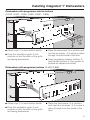
Installing integrated "i" Dishwashers
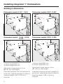
Building in dimensions
Dishwasher models G 601 - G 632
Dishwasher models G 801 - G 832
Dishwasher models G 636 - G 698,
G 975
Dishwasher models G 836 - G 898
1) Niche height 870 mm
2) Niche height 820 mm
1) Niche height 890 mm
2) Niche height 840 mm
Adjustment range approx. 5 cm
(82 -87 cm total height).
Adjustment range approx. 5 cm
(84 - 89 cm total height).
Extended machine feet are available at
extra cost, (special accessory) where a
machine height of 87 to 92 cm is
required.
Extended machine feet are available at
extra cost, (special accessory) where a
machine height of 89 to 94 cm is
required.
6
Installing integrated "i" Dishwashers
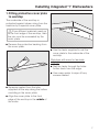
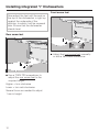
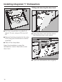
1. Fitting protective cover plate
to worktop
The underside of the worktop is
protected against steam rising from the
machine by a special cover plate.
,If two different materials meet up
at the front edge of the worktop, then
the join must be concealed by the
cover plate.
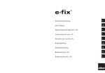
^ Remove the protective backing from
the cover plate.
^ Use the tacks supplied to nail the
cover plate to the underside of the
worktop.
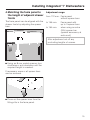
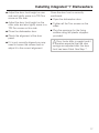
Worktops with wood or laminate
edging:
^ Nail the tacks through the holes
further back from the edge.
^ Use soapy water to wipe off any
excess sealant.
^ Squeeze sealant from the tube
supplied all the way along the hollow
moulding in the cover plate.
^ Align the cover plate to the front
edge of the worktop in the middle of
the niche.
7
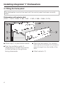
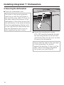
Installing integrated "i" Dishwashers
2. Fitting the facia panel
The dishwasher must not be used until the control panel has been correctly
fitted.
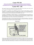
Dishwashers with selector dial
(G 601 - G 624, G 638 - G 686, G 801 - G 824, G 838 - G 884, G 975)
^ Attach cap a to push button switch.
^ Push the ventillation grille b
(depending on model) into position
so that the slats on the grille are
facing downwards.
8
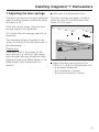
^ Place the facia panel c in position
and use the six screws d to screw in
place through from the inside of the
door.
^ Attach selector e.
Installing integrated "i" Dishwashers
Dishwashers with programme selector buttons
(G 632, G 692 - G 696, G 832, G 892 - G 896)
^ Attach cap a to push button switch.
^ Push the ventillation grille b into
position so that the slats on the grille
are facing downwards.
^ Place the facia panel c in position and
use the six screws d to screw in place
through from the inside of the door.
^ Insert programme selector buttons e
and function buttons f (the number of
buttons will depend on model).
Dishwashers with programme buttons (G 698, G 898)
^ Attach cap a to push button switch.
^ Push the ventillation grille b into
position so that the slats on the grille
are facing downwards.
^ Place the facia panel c in position
and use the six screws d to screw in
place through from the inside of the
door.
9
Installing integrated "i" Dishwashers
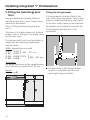
3. Building the dishwasher
into a niche
Connection to water and drainage
should be sited beside and not behind
the dishwasher for accessibility.
Connections are usually made in the
area under the sink. Many kitchen unit
manufacturers provide a cut-out in the
base of the sink base unit for the hoses
to be fed through.
If the base unit has no opening and if
there is not an opening through the
plinth area for connections, one must
be cut.
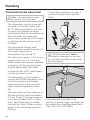
Dishwasher height
^ Adjust the height manually before
installing the dishwasher.
Leave a space of approx. 5 mm
below the worktop to allow the
dishwasher to be pushed back easily
into the recess. Make sure that the
dishwasher stands level.
It is easier to adjust the screw feet if the
weight of the dishwasher is not bearing
down on them.
If possible tip the machine slightly.
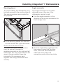
Slides
You will find the slides in the upper
basket of the dishwasher.
They make installation of the
dishwasher easier and protect the floor
from possible damage when moving
the appliance into and out of the
recess. They are also used for
adjusting the height of the rear screw
feet.
Dimensions: 60 x 110 mm.
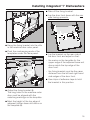
,There must be no electrical
sockets behind the dishwasher.
Danger of overheating and fire risk if
the dishwasher were to be pushed
up against a plug.
^ Fit the slides - with the ratchet at the
rear - under the screw feet.
10
Installing integrated "i" Dishwashers
Securing pieces
Angle connector
To ensure stability, the dishwasher must
be fixed securely to the worktop (step 6).
Two securing pieces are supplied for
this purpose.
The angle connector for the water
drainage hose at the rear of the
dishwasher can be turned.
^ Turn the angle connector in the
direction of the on-site connection for
the drainage hose.
^ Fit the securing pieces into the slots
on both the left and right hand sides.
Granite and marble worktops:
With these worktops the dishwasher
must be securely screwed to
neighbouring units on the right and left
hand sides. For this you will require two
special fixing brackets (these are
included in the accessory pack
together with fitting instructions and
screws).
^ Push the dishwasher right back into
the recess. Ensure that the drain
hose, inlet hose and the electric
cable are laid to reach the
connection point without any kinks.
11
Installing integrated "i" Dishwashers
Front screw feet
Now adjust the feet until the seal on
the top of the dishwasher is right up
against the underside of the
worktop, to which it will be screwed
later. Ensure that the dishwasher
stands level.
Rear screw feet
^ Adjust the front screw feet manually
or with a flat blade screwdriver.
^ Use a TORX T20 screwdriver to
adjust the rear screw feet to the
required height.
Higher = turn clockwise
Lower = turn anti-clockwise
Several turns are needed to adjust
1 mm in height.
12
Installing integrated "i" Dishwashers
4. Matching the facia panel to
the height of adjacent drawer
fronts
Adjustment range:
The facia panel can be aligned with the
drawer fronts by adjusting the spacer
bars.
to 145 mm:
Facia panel with
up to 4 spacer bars
to 154 mm:
when using an extra
(fifth) spacer bar
(special accessory at
extra cost)
from 112 mm: Facia panel
without spacer bars
After adjustment cut off any
protruding lengths of screws.
^ Using an 8 mm socket spanner turn
clockwise or anti-clockwise until the
required height is reached.
If necessary some or all spacer bars
can be removed.
^ Press out the spacer bars from the
fitting slits in the facia panel.
13
Installing integrated "i" Dishwashers
5. Fitting the (matching) door
front
Fixing brackets are already fitted on
stainless steel door fronts. These fronts
cannot be shortened.
(Go to "Fitting and securing the door
front".)
The door of a kitchen base unit (without
drawer front or fittings) is normally used
for the door front.
Fitting the fixing bracket
A fixing bracket must be fitted to the
rear of the door front panel. This is then
used for attaching the door front panel
to the door outer panel on the machine.
Templates are provided to position the
fixing bracket and the door front
accurately.
If a kitchen door front is not available, a
panel with the following dimensions
may be used:
Width: depending on model
G 601 - G 632
440 - 447 mm
G 801 - G 832
G 636 - G 698, G 975
590 - 597 mm
G 836 - G 898
}
}
Thickness:
the same thickness as the neighbouring
door fronts but a minimum of 16 mm.
Height:
Dimension X
14
^ On each side of the fixing bracket
position a template with the rule
markings facing outwards.
Installing integrated "i" Dishwashers
^ Take off the fixing bracket.
^ Lay the door front down with the rear
side facing upwards.
^ Hang the fixing bracket into the slits
in the machine door outer panel.
^ Push the overhanging ends of the
templates under the facia panel.
^ Lay the bracket on the rear side of
the door front and adjust so that:
– the marks on the template for the
upper edge of the adjacent base unit
doors match the top edge of the
door front.
– the fixing bracket must be the same
distance from the left and right hand
side edges of the door front.
^ Use strips of adhesive tape to hold
the bracket in this position.
^ Adjust the fixing bracket a:
The long holes in the machine outer
door must be aligned with the
matching markings on the template.
^ Mark the height of the top edge of
adjacent kitchen base unit doors on
the template b.
15
Installing integrated "i" Dishwashers
Fitting and securing the door front
^ Drill the fixing holes to a depth of
about 10 mm, using a 2.5 mm drill
bit.
^ Hang the door front into the slits in
the machine door outer panel.
^ Secure the fixing bracket to the door
front using the countersunk screws
supplied.
^ Take off the templates.
Keep the templates in case the
dishwasher is ever fitted with a new
door front.
^ Open the dishwasher door slightly.
16
Installing integrated "i" Dishwashers
^ Adjust the door front height on one
side and lightly screw in a T20 Torx
screw on this side.
^ Adjust the door front height on the
other side and also lightly screw in a
T20 Torx screw on this side.
^ Close the dishwasher door.
^ Check the alignment of the door
panel.
^ If it is not correctly aligned you may
need to loosen the screws and readjust it to the correct alignment.
Once the door front is correctly
positioned:
^ Open the dishwasher door.
^ Tighten all the Torx screws on the
sides.
^ Plug the openings for the fixing
screws using the plastic stoppers
provided.
,Door fronts differ in weight and it
is therefore essential that the door
springs are adjusted after the door
front has been fitted. See Step 7.
17
Installing integrated "i" Dishwashers
6. Securing the dishwasher
^ Open the dishwasher door.
The holes in the securing pieces
must line up with the long holes in
the worktop cover plate. If this is not
the case, adjust the position of the
dishwasher in the niche (ensure that
the dishwasher is the same distance
from the neighbouring kitchen units
on the right and left hand sides and
line the dishwasher door front up
with neighbouring door fronts).
^ Screw the countersunk screws
(3.9 x 22) supplied upwards through
the securing pieces on the left and
right hand sides into the work surface
to secure the dishwasher.
Ensure that the seal on the top edge
of the dishwasher fits directly
against the worktop. If this is not the
case, adjust the height adjustable
feet some more (see Step 3).
18
Installing integrated "i" Dishwashers
7. Adjusting the door springs
^ Half open the dishwasher door.
The door springs are correctly adjusted
when the door remains stationary when
left open at 45 °.
The door springs are easier to adjust
when the door is only half open than
when it is fully open.
If the door drops down, then the door
springs need to be tightened.
If it closes then the springs need to be
loosened.
The adjusting screw is located in the
upper front strip at the left hand side of
the dishwasher.
Please note:
If the door front is too heavy for the
door springs (i.e. the door falls open)
then stronger springs should be fitted.
Please contact your Miele dealer or the
Miele Spare Parts Department for
advice.
^ Adjust the door spring with a Torx
T20 or a 1 x 5.5 mm screwdriver until
it is correctly balanced:
- Turn clockwise = tighten
- Turn anti-clockwise = loosen.
19
Installing integrated "i" Dishwashers
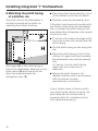
8. Matching the plinth facing
of a kitchen run
^ Place the plinth facing directly in front
of the kitchen run but do not attach.
The plinth area of the dishwasher is
normally covered with a plinth run
matching the kitchen furniture.
^ Carefully open the dishwasher door.
If the door front comes into contact with
the kitchen plinth when the dishwasher
door is opened the plinth facing in the
area behind the dishwasher door needs
to be cut to size.
^ To do this mark where the edge of the
door front comes into contact with the
plinth facing.
^ Cut the plinth facing to size along this
line.
The height (H) of the plinth facing in
front of the dishwasher depends on the
plinth return (R) and how much the
door front extends below the
dishwasher door (P).
^ Place the plinth facing in front of the
kitchen run again and check whether
the dishwasher door can be opened
fully.
If it cannot, trim the plinth facing
again until the correct size is
achieved.
^ Secure the plinth facing to the
adjacent kitchen units in accordance
with the kitchen furniture
manufacturer’s instructions.
If your kitchen does not have a plinth
run matching the kitchen furniture, the
plinth area can be covered with a
separate plinth kit, available at extra
cost (special accessory).
20
Installing built-under "U" model dishwashers
Built-under "U" model
dishwashers
“U” model dishwashers are specially
designed for installing under a
continuous worktop.
– The dishwasher is supplied with the
control panel already fitted.
– The height of the dishwasher front
panel can be adjusted to match
those of neighbouring kitchen units.
The decor panel supplied with the
dishwasher can be taken out and
replaced with a panel to match the
rest of your kitchen.
– A plinth facing to cover the plinth
area is supplied with the dishwasher.
The height of the plinth facing can be
adjusted to match the height of
adjacent plinths. The plinth return is
freely adjustable.
Instructions for installing the
dishwasher are described in the
following sections.
,To ensure stability, "U" model
dishwashers must only be installed
under a continuous worktop which is
securely screwed to neighbouring
units.
,The dishwasher must not be
installed under a hob. The high
radiant temperatures which are
sometimes generated by a hob
could damage the dishwasher.
,On dishwashers with a drying
fan, moist air is expelled through the
vent outlet in the front of the machine
at the end of a programme. It
continues to be expelled for a
certain length of time, or until the
door is opened.
To prevent damaging surrounding
fittings (e. g. worktops with wood
edging) the fan running time can be
increased by 14 minutes (see the
Operating Instruction manual for the
dishwasher).
21
Installing built-under "U" model dishwashers
Building in dimensions:
Dishwasher models G 836 - G 898
Dishwasher models G 636 - G 698
G 975
1) Niche height 890 mm
2) Niche height 840 mm
1) Niche height 870 mm
2) Niche height 820 mm
Adjustment range approx. 5 cm (82 87 cm total height).
Extended machine feet are available at
extra cost, (special accessory) if you
wish to increase the machine height to
between 87 and 92 cm.
22
Adjustment range approx. 5 cm (84 89 cm total height).
Extended machine feet are available at
extra cost, (special accessory) if you
wish to increase the machine height to
between 89 and 94 cm.
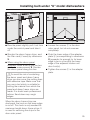
Installing built-under "U" model dishwashers
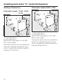
1. Fitting protective cover plate
to worktop
The underside of the worktop is
protected against steam rising from the
machine by a special cover plate.
,If two different materials meet up
at the front edge of the worktop, then
the join must be concealed by the
cover plate.
^ Remove the protective backing from
the cover plate.
^ Use the tacks supplied to nail the
cover plate to the underside of the
worktop.
Worktops with wood or laminate
edging:
^ Nail the tacks through the holes
which are further back from the edge.
^ Use soapy water to wipe off any
excess sealant.
^ Squeeze sealant from the tube
supplied all the way along the hollow
moulding in the cover plate.
^ Align the cover plate to the front
edge of the worktop in the middle of
the niche.
23
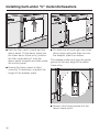
Installing built-under "U" model dishwashers
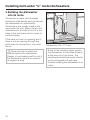
2. Building the dishwasher
into its niche
Connection to water and drainage
should be sited beside and not behind
the dishwasher for accessibility.
Connections are usually made in the
area under the sink. Many kitchen unit
manufacturers provide a cut-out in the
base of the sink base unit for hoses to
be fed through.
If the base unit has no opening and if
there is not an opening through the
plinth area for connections, one must
be cut.
,There must be no electrical
sockets behind the dishwasher.
Danger of overheating and fire risk if
the dishwasher were to be pushed
up against a plug.
24
Dimensions: 60 x 110 mm.
Some of the following steps require
the dishwasher to be pulled forward
a little way out of the niche. The
plumbing and electrical points should
not be connected until you have
finished installing the dishwasher in its
niche.
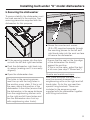
Installing built-under "U" model dishwashers
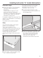
Dishwasher height
^ Adjust the height of the dishwasher
manuually before installing the
dishwasher.
Leave a space of approx. 5 mm
below the worktop to allow the
dishwasher to be pushed back easily
into the recess. Make sure that the
dishwasher stands level.
The angle connector for the water
drainage hose at the rear of the
dishwasher can be turned.
^ Turn the angle connector in the
direction of the on-site connection for
the drainage hose.
It is easier to adjust the screw feet if the
weight of the dishwasher is not bearing
down on them.
If possible tip the machine slightly.
Slides
You will find the slides in the upper
basket of your dishwasher.
They make installation of the
dishwasher easier and protect the floor
from possible damage when moving
the appliance into and out of the
recess. They are also used for
adjusting the height of the rear screw
feet.
^ Push the dishwasher right back into
the recess. Ensure that the drain
hose, inlet hose and the electric
cable are laid to reach the
connection point without any kinks.
^ Fit the slides - with the ratchet at the
rear - under the screw feet.
25
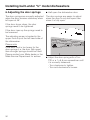
Installing built-under "U" model dishwashers
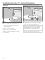
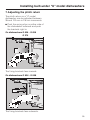
Screw feet
^ Use a TORX T20 screwdriver to
adjust the rear screw feet to the
required height.
Higher = turn clockwise
Lower = turn anti-clockwise
Several turns are needed to adjust 1
mm in height.
26
^ Adjust the front screw feet manually
or with a flat blade screwdriver.
Screw the feet out until the seal on
the dishwasher is right up against
the underside of the worktop, to
which it will be screwed later. Ensure
that the dishwasher stands level.
Installing built-under "U" model dishwashers
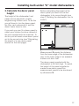
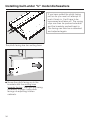
3. Calculate the decor panel
height
The height of the dishwasher front
panel can be adjusted to match
neighbouring kitchen units. To do this
you will have to trim the decor panel,
the filler card underneath it and the
decor frame strips to size.
Before calculating the height of the
decor panel you must first set the
dishwasher to its correct height (see
step 2 "Building the dishwasher into its
niche").
If you wish you can fit a decor panel to
match your kitchen furniture instead of
the one supplied with the machine. To
do this you will need a new decor panel
cut to the correct size (see "Calculating
the height of a new decor panel"
section on the next page).
Measurement X equals the distance
from the lower edge of the dishwasher
door to the lower edge of an adjacent
kitchen unit door front.
The decor panel supplied with the
dishwasher is 604 mm high. To match
the height of the panel supplied or
create a new decor panel this
measurement needs to be shortened
by dimension X.
27
Installing built-under "U" model dishwashers
Adapting the height of the decor
panel supplied
4. Matching the plinth facing of
a kitchen run
^ Mark the measurement X on the left
and right hand side of the decor
panel and on the decor frame strips.
^ Take off and shorten the decor frame
strips, the decor panel and the filler
card (see Step 4).
Calculating the height of a new decor
panel
You can substitute the decor panel
supplied with the dishwasher with a
panel to match your kitchen decor.
The dimensions for the new panel must
be as follows:
Width:
587 mm
Thickness:
minimum 1 mm and maximum 4 mm.
The filler card fitted behind the decor
panel supplied with the machine is not
required for new panels if they are
2 mm or more in thickness.
Height:
604 mm less dimension X mm
^ Mark dimension X on the left and
right hand side of the decor frame
strips.
^ Take off the decor frame strips, the
decor panel and the filler card, and
shorten the decor frame strips, and
the filler card (if used). See Step 4.
28
^ Pull the dishwasher out of its recess
enough to allow easy access to the
front panel fixing screws on either
side of the door.
^ Loosen and remove the fixing screws
and push the side decor frame strips
downwards until they are free of the
dishwasher outer door panel and can
be removed.
Installing built-under "U" model dishwashers
^ Bow the panel slightly, pull it out from
under the control panel and take it
off.
^ Loosen the screws a in the door
outer panel, but do not unscrew
completely.
^ Shorten the decor frame strips, and
the filler card (if used) by dimension
X.
^ Push the lower edge of the adapter
plate b (corresponding to dimension
X) upwards far enough for its lower
edge to be in a line with the lower
edge of the adjacent kitchen unit
door front(s).
^ When using the decor panel
supplied: Draw a line to join the two
marks for measurement X. Shorten
the decor panel along this line.
,To avoid the risk of scratching
the decor panel and decor frame
strips you can cover the cutting lines
with adhesive tape. Make sure that
you use a tool which is suitable for
cutting the material from which the
panel and decor frame strips are
made. If in doubt seek professional
advice. Sand down any rough
edges.
^ Tighten the screws a in the adapter
plate.
When the decor frame strips are
shortened, the hook on the lower edge
is cut off. This hook is only needed for
maximum length decor frame strips. It
is used for securing the strips to the
door outer panel.
29
Installing built-under "U" model dishwashers
^ Refit the filler card (if used) and the
decor panel. Fit the decor panel into
the lower decor frame strip, position
the filler card behind it, bow the
decor panel forwards and slide under
the control panel.
^ Put back the left and right hand side
decor strips and push them up over
the adapter plate from below.
The adapter plate must grip the guide
groove at the rear edge of the decor
frame strip.
^ Ensure the decor panel is fitted
correctly. If necessary, re-adjust the
height of the adapter plate.
^ Screw in the fixing screws into the
decor frame strips.
30
Installing built-under "U" model dishwashers
5. Securing the dishwasher
To ensure stability, the dishwasher must
be fixed securely to the worktop. Two
securing pieces are supplied with the
dishwasher for this purpose.
^ Screw the countersunk screws
(3.9 x 22) supplied upwards through
the securing pieces on the left and
right hand sides into the work surface
to secure the dishwasher.
^ Fit the securing pieces into the slots
on both the left and right hand sides.
^ Push the dishwasher right back into
its recess (making sure it is correctly
aligned).
^ Open the dishwasher door.
The holes in the securing pieces
must line up with the long holes in
the worktop cover plate. If this is not
the case, adjust the position of the
dishwasher in the niche (ensure that
the dishwasher is the same distance
from the neighbouring kitchen units
on the right and left hand sides and
line the dishwasher door front up
with neighbouring door fronts).
Ensure that the seal on the top edge
of the dishwasher fits directly
against the worktop.
If this is not the case, adjust the feet
a bit more (see step 2 "Screw feet").
Granite and marble worktops:
With these worktops the dishwasher
must be securely screwed to
neighbouring units on the right and left
hand sides. To do this you need two
special fixing brackets. These are
included in the accessory pack
supplied with the dishwasher together
with fitting instructions.
31
Installing built-under "U" model dishwashers
6. Adjusting the door springs
^ Half open the dishwasher door.
The door springs are correctly adjusted
when the door remains stationary when
left open at 45°.
The door springs are easier to adjust
when the door is only half open than
when it is fully open.
If the door drops down, the door
springs need to be tightened.
If the door rises up the springs need to
be loosened.
The adjusting screw is located in the
upper front strip at the left hand side of
the dishwasher.
Please note:
If the door front is too heavy for the
door springs (i.e. the door falls open)
then stronger springs should be fitted.
Please contact your Miele dealer or the
Miele Service Department for advice.
32
^ Adjust the door spring with a Torx
T20 or a 1 x 5.5 mm screwdriver until
it is correctly balanced:
- Turn clockwise to tighten.
- Turn anti-clockwise to loosen.
Installing built-under "U" model dishwashers
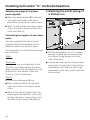
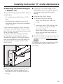
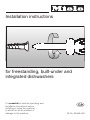
7. Adjusting the plinth return
The plinth return on a "U" model
dishwasher can be adjusted between
35 and 100 mm in 2.5 mm increments.
^ Push the spring clips on either side of
the dishwasher outwards and push
the brackets right in.
On dishwashers G 636 - G 698
G 975
The fixing brackets face inwards.
On dishwashers G 836 - G 898
The fixing brackets face outwards.
33
Installing built-under "U" model dishwashers
If you have pulled the plinth facing
out too far you must not attempt to
push it back in. It will have to be
unscrewed and taken off. The spring
clips can then be pushed outwards
and the brackets pushed back in.
The facing can then be re-attached
and adjusted again.
The plinth facing has two cutting lines.
^ Screw the plinth facing on to the
brackets with the cutting lines
towards the top. Then pull the facing
out evenly to align it with plinth
facings on adjoining kitchen
cabinets.
34
Installing built-under "U" model dishwashers
8. Matching the plinth facing of
a kitchen run
The plinth facing supplied will fit without
modification:
– for a maximum plinth return of 100
mm
– and when the machine is set to its
maximum height (feet fully extended
- max. 5 cm).
If the machine height is lower than the
maximum, and the plinth recess is less
than 100 mm, the plinth facing will need
to be trimmed to size.
To prevent the door hitting the plinth
facing when the dishwasher door is
opened the height of the plinth facing
has to be adjusted to suit the height of
the dishwasher and the depth of the
plinth return.
^ Using the front lower edge of the
dishwasher door as a guide, draw a
horizontal line across the plinth
facing.
^ Unscrew the plinth facing.
^ To shorten the plinth facing:
- either trim along this line with
a saw;
or
– cut along one of the cutting lines
if it is close enough to the line
you have drawn.
Score the cutting line along the
plinth facing and then break off
the excess.
^ Screw the plinth facing back onto the
brackets, with the cutting line at the
bottom.
If the door still does not open smoothly
the plinth facing may need further
trimming.
^ Carefully open the dishwasher door
until the rear bottom edge of the
dishwasher door touches the plinth
facing.
35
Electrical connection
,Please follow the installation
instructions carefully.
All electrical work should be carried
out only by a suitably qualified and
competent person, in strict
accordance with national and local
safety regulations.
Ensure power is not supplied to the
appliance while installation work is
being carried out.
This dishwasher is supplied with a
mains cable and moulded plug ready
for connection to an a.c. single phase
supply, (230 -240 V 50 Hz for the UK
and Australia) via a fused plug and
suitable switched socket which is easily
accessible after installation.
^ The voltage, rated load and fuse
rating are given on the data plate
located above the door. Please
ensure that these match the
household mains supply.
For extra safety it is advisable to install
a residual current device (RCD), with a
trip current of 30 mA (in accordance
with DIN VDE 0664, VDE 0100 Section
739).
^ Do not connect via an extension lead.
Danger of overheating.
,If the connection cable is
damaged it must be replaced with a
complete connection box and cable
by a Miele approved service
technician only.
Important
If this machine is fitted with a
non-rewireable plug (BS 1363) and the
socket outlets are not suitable for the
plug supplied or if the existing plug
needs to be replaced by a new one, the
old plug will need to be cut off and an
appropriate plug fitted. The fuse carrier
and the fuse should be removed from
the old plug and disposed of.
The plug cut from the cable should then
be disposed of and on no account be
inserted into any socket elsewhere in
the house (electric shock hazard).
The fuse cover must be refitted when
changing the fuse, and if the fuse cover
is lost, the plug must not be used until a
suitable replacement is obtained. The
colour of the correct replacement cover
is that of the coloured insert in the base
of the plug, or the colour that is
embossed in words on the base of the
plug (as applicable to the design of
plug fitted).
The correct fuse rating of the
replacement fuses that are ASTA
approved to BS 1362 should be fitted.
Replacement fuse covers may be
purchased from your local electrical
supplier or Miele Service Agent.
36
Electrical connection
The wires in the mains lead are
coloured in accordance with the
following code:
Green/yellow = earth
Blue
= neutral
Brown
= live
If the colours of the wires in the mains
lead of this appliance do not
correspond with the coloured markings
identifying the terminals of your plug,
proceed as follows:
^ The wire which is coloured green and
yellow must be connected to the
terminal in the plug which is marked
with the letter E or by the earth
symbol z or coloured green, or
green and yellow.
^ The wire which is coloured blue must
be connected to the terminal in the
plug which is marked with the letter N
or coloured black.
^ The wire which is coloured brown
must be connected to the terminal in
the plug which is marked with the
letter L or coloured red (UK), or
marked with the letter A
(AUSTRALIA).
WARNING:
THIS APPLIANCE
MUST BE EARTHED
37
Plumbing
Connection to the water inlet
,Water in the dishwasher must
not be used as drinking water.
If the water pressure is too high, a
pressure reducer valve must be
fitted.
– The dishwasher may be connected
to a cold or hot water supply, max.
60 °C. When connected to a hot water supply all programme stages
which would otherwise be carried out
with cold water (pre-wash and
interim rinse) as well as the Pre-wash
programme will be carried out with
hot water.
– The programme "Energy save"
(without heater) needs connection to
a hot water supply with a
temperature of at least 45 °C.
– The inlet hose is approx. 1.5 m long; a
longer hose (4 m), or a 1.5 m long
flexible metal hose tested to withstand
pressure of 140 bar may be bought
from the Miele Spare Parts Dept.
!The inlet hose must not be
shortened or damaged in any way
as it contains electrical components
(see illustration).
– A stopcock with a 3/4 " male thread
must be provided on site.
– The dishwasher is constructed to
comply with DVGW regulations, and
may be connected to a suitable
supply without an extra non-return
valve if national regulations allow
this.
– The water pressure (flow pressure at
the take-off point) must be between
0.3 and 10 bar. If the water pressure
is too low the Water "inlet" or "inlet /
drain" light (depending on model)
may light up, (see "Problem solving
guide" in the Operating Instruction
booklet).
38
If the stopcock is situated in the
worktop, a special angle connector can
be ordered from the Miele Spare Parts
Dept. (Part No. 04 274 820).
Plumbing
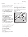
Drainage
Venting the drainage system
– The machine drainage system is
fitted with a non-return valve, which
prevents dirty water from flowing
back into the machine via the drain
hose.
^ Open the dishwasher door fully.
– The dishwasher is supplied with an
approx. 1.5 m long flexible drain hose
with an internal diameter of 22 mm.
– The drain hose can be extended
using a connection piece and an
extra drain hose, (up to max. 4
metres).
If the site drain connection is situated
lower than the guide path for the
bottom basket rollers in the open door
the drainage system must be vented.
Otherwise a siphoning effect during a
programme can cause the machine to
empty itself of water.
To vent:
– A hose clip is supplied for
connecting the drain hose to the
on-site drainage outlet.
– The connection socket on the
dishwasher can be turned. The hose
can thus be laid to the right or left
without needing to loosen the hose
clip supplied.
– The drain system must not exceed 4
metres. The drain pump has a
maximum delivery head of 1 metre.
– The on-site water pipe connection for
the drain hose may be designed to fit
more than one diameter of hose. The
connection socket must be
shortened if it juts too far into the
drain hose. Otherwise the drain hose
can become blocked.
^ Cut off the top of the vent valve in the
wash cabinet.
– The drain hose must not be
shortened.
– Ensure that the drain hose is laid so
that it is free from kinks.
39
Optional accessories
"i"- Integrated dishwashers
If you would like to...
you will need to order...
...convert an integrated ("i") dishwasher
to a built under "U" model
...a GDU decor set conversion kit
available in: white
dark brown
black
... build the dishwasher into a kitchen which ...a separate plinth kit
does not have a matching plinth run
available in: white
black
... adjust the height of the dishwasher to
between 87 cm and 92 cm (G 601 - G 632,
G 636 - G 698, G 975) or between 89 cm
and 94 cm (G 801 - G 832, G 836 - G 898)
...a kit with extended machine feet
...to match the facia panel of the dishwasher ...a spacer bar
to adjacent drawer fronts with dimensions
available in: white
of between 145 mm and 154 mm
dark brown
black
stainless steel
Built-under "U" model dishwashers
If you would like to …
you will need to order …
...adjust the height of the
dishwasher to between 87 cm and 92
cm
...a kit with extended machine feet
Freestanding dishwasher
If you would like to...
You will need to order ...
...convert a freestanding dishwasher
to a built under "U" model
...a UBS conversion kit
40
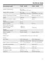
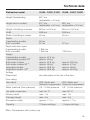
Technical data
Dishwasher model
G 601 - G 632
G 801 - G 832
Height Freestanding
84.7 cm
(adjustable + 2.0 cm)
-
Height built-in models
81.7 cm
(adjustable + 5.0 cm)
83.7 cm
(adjustable + 5.0 cm)
Height of building in recess
82 cm (+ 5.0 cm)
84 cm (+ 5.0 cm)
Width
44.8 cm
44.8 cm
Width of building in recess
45 cm
45 cm
Depth:
Freestanding models
Built-in models
60 cm
57 cm
57 cm
Depth with open door:
Freestanding models
Built-in models
118.5 cm
115.5 cm
120.5 cm
Weight:
Freestanding model
Built-in models
approx. 54 kg
approx. 48 kg
approx. 49 kg
Voltage
Rated load
see data plate on the top of the door
Fusing
Test marks
VDE, Radio and
VDE, Radio and
Television suppressed Television suppressed
Water pressure (flow pressure)
0.3 - 10 bar pressure
0.3 - 10 bar pressure
Hot water connection
max. 60 °C
max. 60 °C
Delivery head
max. 1 m
max. 1 m
Drainage length
max. 4 m
max. 4 m
Connection cable
approx. 1.7 m
approx. 1.7 m
Capacity
8 place settings
9 place settings
41
Technical data
Dishwasher model
G 636 - G 645, G 975
Height Freestanding
84.7 cm (adjustable + 4.0 cm)
Height built-in models
81.7 cm (adjustable + 5.0 cm)
Height of building in recess
82 cm (+ 5.0 cm)
Width
59.8 cm
Width of building in recess
60 cm
Depth:
Freestanding models
Built-in models
60 cm
57 cm
Depth with door open:
Freestanding models
Built-in models
118.5 cm
115.5 cm
Weight:
Freestanding models
Freestanding models SC#
Built-under models
Built-under models SC #
Integrated models
Integrated models SC#
approx. 60 kg
approx. 61.5 kg
approx. 56 kg
approx. 57.5 kg
approx. 51.5 kg
approx. 53 kg
Voltage
Rated load
see data plate on the top of the door
Fuse rating
Test marks
VDE, Radio and Television suppressed
Water pressure (flow pressure)
0.3 - 10 bar pressure
Hot water connection
max. 60 °C
Delivery head
max. 1 m
Drainage length
max. 4 m
Connection cable
approx. 1.7 m
Capacity
12 place settings
SC# = Dishwashers with cutlery tray
42
Technical data
Dishwasher model
G 646 - G 657, G 692
G 846 - G 857, G 892
Height Freestanding
84.7 cm
(adjustable + 4.0 cm)
-
Height built-in models
81.7 cm
(adjustable + 5.0 cm)
83.7 cm
(adjustable + 5.0 cm)
Height of building in recess
82 cm (+ 5.0 cm)
84 cm (+ 5.0 cm)
Width
59.8 cm
59.8 cm
Width of building in recess
60 cm
60 cm
Depth:
Freestanding models
Built-in models
60 cm
57 cm
57 cm
Depth with door open:
Freestanding models
Built-in models
118.5 cm
115.5 cm
120.5 cm
Weight:
Freestanding models
Freestanding models SC#
Built-under models
Built-under models SC #
Integrated models
Integrated models SC#
approx. 61.5 kg
approx. 63 kg
approx. 57.5 kg
approx. 59 kg
approx. 53.5 kg
approx. 55.5 kg
approx. 59.5 kg
approx. 61 kg
approx. 55 kg
approx. 56.5 kg
Voltage
Rated load
see data plate on the top of the door
Fuse rating
Test marks
VDE, Radio and
VDE, Radio and
Television suppressed Television suppressed
Water pressure (flow pressure)
0.3 - 10 bar pressure
0.3 - 10 bar pressure
Hot water connection
max. 60 °C
max. 60 °C
Delivery head
max. 1 m
max. 1 m
Drainage length
max. 4 m
max. 4 m
Connection cable
approx. 1.7 m
approx. 1.7 m
Capacity
12 place settings
14 place settings
SC# = Dishwashers with cutlery tray
43
Technical data
Dishwasher model
G 681 - G 689
G 693 - G 698
G 881 - G 889
G 893 - G 898
Height Freestanding
84.7 cm
(adjustable + 4.0 cm)
-
Height built-in models
81.7 cm
(adjustable + 5.0 cm)
83.7 cm
(adjustable + 5.0 cm)
Height of building in recess
82 cm (+ 5.0 cm)
84 cm (+ 5.0 cm)
Width
59.8 cm
59.8 cm
Width of building in recess
60 cm
60 cm
Depth:
Freestanding models
Built-in models
60 cm
57 cm
57 cm
Depth with door open:
Freestanding models
Built-in models
118.5 cm
115.5 cm
120.5 cm
Weight:
Freestanding model
Freestanding model SC#
Built-under models
Built-under models SC #
Integrated models
Integrated models SC#
approx. 64 kg
approx. 65.5 kg
approx. 60 kg
approx. 61.5 kg
approx. 55.5 kg
approx. 57 kg
approx. 60.5 kg
approx. 62 kg
approx. 56 kg
approx. 57.5 kg
Voltage
Rated load
see data plate on the top of the door
Fusing
Test marks
VDE, Radio and
VDE, Radio and
Television suppressed Television suppressed
Water pressure (flow pressure)
0.3 - 10 bar pressure
0.3 - 10 bar pressure
Hot water connection
max. 60 °C
max. 60 °C
Delivery head
max. 1 m
max. 1 m
Drainage length
max. 4 m
max. 4 m
Connection cable
approx. 1.7 m
approx. 1.7 m
Capacity
12 place settings
14 place settings
SC # = Dishwashers with cutlery tray
44
45
46
47
Alteration rights reserved (NovoPlusB,P,S) / 1206
M.-Nr. 05 565 043 / 01
en - GB