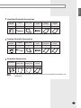
1
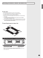
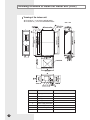
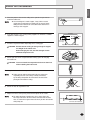
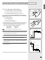
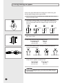
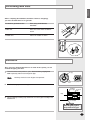
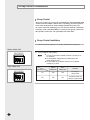
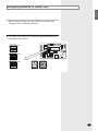
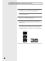
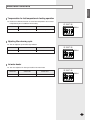
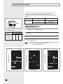
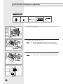
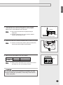
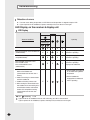
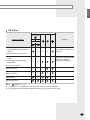
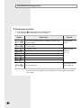
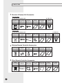
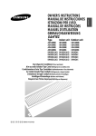
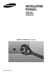
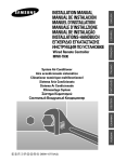
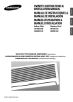
ENGLISH ESPAÑOL DEUTSCH RUSSIAN E§§HNIKA Duct-type Air Conditioner (Cool & Heat) Aire acondicionador Tipo Canal (Enfriamiento & Calefacción) Climatiseur de type Conduit (Refroidissement et Chauffage) Ar Condicionado Tipo Conduto (Refrigeração e Aquecimento) Climatiseur de type Conduit (Refroidissement et Chauffage) Ventiltype Klimaanlage (Kühlen und Wärmen) KÏÈÌ·ÙÈÛÙÈÎfi T‡Ô˘ AÂÚ·ÁˆÁÔ‡ (æ‡Í˘ Î·È £¤ÚÌ·ÓÛ˘) ÇÓÁ‰Û¯Ì˚È äÓ̉ˈËÓÌ íÛ·ÌÓ„Ó íËÔ‡ (éı·ʉÂÌËÂ Ë é·Ó„‚) PORTUGUÊS ITALIANO HH105ECM HH140ECM HH175ECM HH175EZM FRANÇAIS INSTALLATION MANUAL MANUAL DE INSTALACIÓN MANUEL D’INSTALLATION MANUALE D’INSTALLZIONE MANUAL DE INSTALAÇÃO INSTALLATIONS-HANDBUCH E°XEIPI¢IO E°KATA™TA™H™ àçëíêìäñàü èé ìëíÄçéÇäÖ E S F I P D G R DB98-08778A(3) Contents Chapter Chapter DU C T IN S TALLATION ■ Preparation for installation . . . . . . . . . . . . . . . . . . . . . . . . . . . . . . 4 ■ Deciding on where to install the indoor unit . . . . . . . . . . . . . . . . . 5 ■ Indoor unit installation . . . . . . . . . . . . . . . . . . . . . . . . . . . . . . . . . . 7 ■ Purging the unit . . . . . . . . . . . . . . . . . . . . . . . . . . . . . . . . . . . . . . 8 ■ Connecting the indoor unit assembly piping . . . . . . . . . . . . . . . . . 9 ■ Cutting/Flaring the pipes . . . . . . . . . . . . . . . . . . . . . . . . . . . . . . . . 10 ■ Performing leak tests . . . . . . . . . . . . . . . . . . . . . . . . . . . . . . . . . . 11 ■ Insulation . . . . . . . . . . . . . . . . . . . . . . . . . . . . . . . . . . . . . . . . . . . 11 ■ Drain hose installation . . . . . . . . . . . . . . . . . . . . . . . . . . . . . . . . . 12 ■ Connecting the connection cord . . . . . . . . . . . . . . . . . . . . . . . . . . 14 ■ Group control installation . . . . . . . . . . . . . . . . . . . . . . . . . . . . . . . 16 ■ Assigning address to indoor unit . . . . . . . . . . . . . . . . . . . . . . . . . 17 ■ Additional functions . . . . . . . . . . . . . . . . . . . . . . . . . . . . . . . . . . . 19 ■ Increasing fan speed . . . . . . . . . . . . . . . . . . . . . . . . . . . . . . . . . . 20 ■ Air filter installation (Optional) . . . . . . . . . . . . . . . . . . . . . . . . . . . . 21 ■ Drain pump installation (Optional) . . . . . . . . . . . . . . . . . . . . . . . . 22 ■ Troubleshooting . . . . . . . . . . . . . . . . . . . . . . . . . . . . . . . . . . . . . . 24 OPTIONAL ACCESSORIES ■ E-2 Parts list . . . . . . . . . . . . . . . . . . . . . . . . . . . . . . . . . . . . . . . . . . . . 28 ENGLISH Chapter DUCT INSTALLATION ■ ■ ■ ■ ■ ■ ■ ■ ■ ■ ■ ■ ■ ■ ■ ■ ■ Preparation for installation . . . . . . . . . . . . . . . . . . . . . 4 Deciding on where to install the indoor unit . . . . . . . . 5 Indoor unit installation . . . . . . . . . . . . . . . . . . . . . . . . . 7 Purging the unit . . . . . . . . . . . . . . . . . . . . . . . . . . . . . 8 Connecting the indoor unit assembly piping . . . . . . . . 9 Cutting/Flaring the pipes . . . . . . . . . . . . . . . . . . . . . . 10 Performing leak tests . . . . . . . . . . . . . . . . . . . . . . . . 11 Insulation . . . . . . . . . . . . . . . . . . . . . . . . . . . . . . . . . 11 Drain hose installation . . . . . . . . . . . . . . . . . . . . . . . 12 Connecting the connection cord . . . . . . . . . . . . . . . . 14 Group control installation . . . . . . . . . . . . . . . . . . . . . . 16 Assigning address to indoor unit . . . . . . . . . . . . . . . 17 Additional functions . . . . . . . . . . . . . . . . . . . . . . . . . 19 Increasing fan speed . . . . . . . . . . . . . . . . . . . . . . . . 20 Air filter installation (Optional) . . . . . . . . . . . . . . . . . . 21 Drain pump installation (Optional) . . . . . . . . . . . . . . 22 Troubleshooting . . . . . . . . . . . . . . . . . . . . . . . . . . . . 24 E-3 Preparation for installation When deciding on the location of the air conditioner with the owner, the following restrictions must be taken into account. General Do NOT install the air conditioner in a location where it will come into contact with the following elements: ◆ ◆ ◆ ◆ ◆ Combustible gases Saline air Machine oil Sulphide gas Special environmental conditions If you must install the unit in such conditions, first consult your dealer. Accessories ◆ The following accessories are supplied with the indoor unit. The type and quantity may differ depending on the specifications. Owner’s Instructions NS NES OWNER’S INSTRUCTIO INSTRUCCIO MANUAL DE PER L’USO ISTRUZIONIINSTRU ˝ES MANUAL DE N MANUEL D’UTILISATIO ANWEISUNG GEBRAUCHS Air Conditioner Splut-type Room stico sistema Split dom ad unit Separate Aire acondicionado d’aria per ambienti Condizionatorede ar condicionado tipo Split Aparelho type s par Climatiseur de Geteilte raumklimaanlage E-4 Installation Manual Pattern Sheet Drain Plug NS NES OWNER’S INSTRUCTIO INSTRUCCIO MANUAL DE PER L’USO ISTRUZIONIINSTRU ˝ES MANUAL DE N MANUEL D’UTILISATIO ANWEISUNG GEBRAUCHS Air Conditioner Splut-type Room stico sistema Split dom ad unit Separate Aire acondicionado d’aria per ambienti Condizionatorede ar condicionado tipo Split Aparelho type s par Climatiseur de Geteilte raumklimaanlage Insulation Drain Insulation Cover Pipe Insulation pipe Insulation Drain Pipe Nut Rubber Cable-Tie Drain socket ENGLISH Deciding on where to install the indoor unit Indoor Unit ◆ ◆ ◆ ◆ There must be no obstacles near the air inlet and outlet. Install the indoor unit on a ceiling that can support its weight. Maintain sufficient clearance around the indoor unit. Make sure that the water dripping from the drain hose runs away correctly and safely. ◆ The indoor unit must be installed in this way, that they are out of public access. (Not touchable by the users) ◆ After connecting a chamber, insulate the connection part between the indoor unit and the chamber with t10 or thicker insulation. Otherwise, there can be air leak or dew from the connection part. 5mm 5mm Space Requirements for Indoor Unit 1210mm x 433mm or more (A space for repair and service) You must have 5mm or more space between the ceiling and the bottom of indoor unit. Otherwise, the noise from the vibration of indoor unit may bother the user. When the ceiling is under construction, the hole for check-up must be made to take service, clean and repair the unit. E-5 Deciding on where to install the indoor unit (Cont.) Drawing of the indoor unit ◆ The inside of ( ) is for HH105/140ECM models. ◆ The outside of ( ) is for HH175ECM/EZM models. Name No. E-6 Unit : mm Remark 1 Liquid pipe connection ø9.52 2 Gas pipe connection ø19.05 3 Drain pipe connection 4 Drain pipe connection 5 Power supply connection 6 Air discharge flange 7 Air suction flange 8 Hook For M8~M10 ENGLISH Indoor unit installation Place the pattern sheet on the ceiling at the spot where you want to install the indoor unit. Note ◆ Since the diagram is made of paper, it may shrink or stretch slightly due to temperature or humidity. For this reason, before drilling the holes maintain the correct dimensions between the markings; refer to page 6. 1 2 Concrete Insert bolt anchors. Use existing ceiling supports or construct a suitable support as shown in figure. Insert Hole in anchor Hole in plug 3 Install the suspension bolts depending on the ceiling type. Suspension bolt(M8)-field supply IMPORTANT Ensure that the ceiling is strong enough to support the weight of the indoor unit. Before hanging the unit, test the strength of each attached suspension bolt. 4 Ceiling support Screw eight nuts to the suspension bolts making space for hanging the indoor unit. IMPORTANT You must install the suspension bolts more than four when installing the indoor unit. 5 Hang the indoor unit to the suspension bolts between two nuts. Note ◆ Tubing must be laid and connected inside the ceiling when suspending the unit. If the ceiling is already constructed, lay the tubing into position for connection to the unit before placing the unit inside the ceiling. 6 Screw the nuts to suspend the unit. 7 Adjust level of the unit by using measurement plate for all 4 sides. Note ◆ For proper drainage of condensate, give a 10mm slant to the left or right side of the unit which will be connected with the drain hose, as shown in the figure. Make a tilt when you wish to install the drain pump, too. Rubber 10mm Drain hose connection port E-7 Purging the unit On delivery, the indoor unit is loaded with an inert nitrogen gas. All this gas must therefore be purged before connecting the assembly piping. To purge the inert gas, proceed as follows. Unscrew the caps at the end of each pipe. Result: Note E-8 All inert gas escapes from the indoor unit. ◆ To prevent dirt or foreign objects from getting into the pipes during installation, do NOT remove the caps completely until you are ready to connect the piping. ENGLISH Connecting the indoor unit assembly piping There are two refrigerant pipes of different diameters: ◆ A smaller one(9.52mm, 3/8") for the liquid refrigerant ◆ A larger one(19.05mm, 3/4") for the gas refrigerant A Drain pump hose connection port Gas refrigerant port ◆ The thickness of tube should not less than 1.0mm. ◆ The inside of copper tube must be clean & has no dust. The connection procedure for the refrigerant pipes varies according to the exit position of the pipes from the indoor unit, as seen when facing the indoor in the “A” side. Liquid refrigerant port ◆ Liquid refrigerant port Drain hose connection port ◆ Gas refrigerant port ◆ Drain hose connection port ◆ Drain pump hose connection port 1 Remove the protection caps on the pipes and connect the assembly pipes to each pipe, tightening the nuts, first manually and then with a torque wrench, a spanner applying the following torque. Outer Diameter 9.52 mm (3/8") 19.05 mm (3/4") Note 2 Torque (kgf•cm) 250~280 990~1210 ◆ If the pipes must be shortened refer to page 10. a. When the indoor unit is above the outdoor unit Indoor unit Must use insulator which is thick enough to cover the refrigerant tube to protect the condensate water on the outside of pipe falling onto the floor and the efficiency of the unit will be better. Outdoor unit 3 Cut off any excess foam insulation. 4 Be sure that there must be no crack or wave on the bended area. 5 It would be necessary to double the insulation thickness (10mm or more) to prevent condensation even on the insulator when if the installed area is warm and humid. b. When the outdoor unit is above the indoor unit Outdoor unit 6 Shape an oil trap as shown in figure the oil trap must be formed every level difference of 10m. Oil trap(suction tube) Indoor unit E-9 Cutting/Flaring the pipes Connect the pipe within 50m and cutting pieces will not be gone into the pipe as being clean to pipe section. 1 Make sure that you have the required tools available (pipe cutter, reamer, flaring tool and pipe holder). 2 If you wish to shorten the pipes, cut it with a pipe cutter, taking care to ensure that the cut edge remains at a 90° angle with the side of the pipe. Refer to the illustrations below for examples of edges cut correctly and incorrectly. O 90 Oblique Rough Burr 3 To prevent any gas from leaking out, remove all burrs at the cut edge of the pipe, using a reamer. 4 Slide a flare nut on to the pipe and modify the flare. Outer Diameter (D) 9.52 mm (3/8") 19.05 mm (3/4") 5 Check that the flaring is correct, referring to the illustrations below for examples of incorrect flaring. Inclined 6 Depth (A) 1.8 mm 2.2 mm Damaged Surface Cracked Uneven Thickness Align the pipes and tighten the flare nuts first manually and then with a torque wrench, applying the following torque. Outer Diameter 9.52 mm (3/8") 19.05 mm (3/4") Torque (kgf•cm) 250~280 990~1210 CAUTION ◆ In case of welding the pipe, you must weld with nitrogen gas blowing. E-10 ENGLISH Performing leak tests Before completing the installation (insulation of the hose and piping), you must check that there are no gas leaks. To check for gas leaks on the... Then, using a leak detector, check the... Indoor unit Flare nuts at the end of sections A and B. Outdoor unit Valves on sections C and D. B A D C Insulation Once you have checked that there are no leaks in the system, you can insulate the piping and hose. 1 To avoid condensation problems, place heat-resistant polyethylene foam separately around each refrigerant pipe. Note No gap ◆ Always make the seam of pipes face upwards. Heat resistant polyethylene foam 2 Wind insulating tape around the pipes. Insulation cover pipe Insulation pipe Body 3 Finish wrapping insulating tape around the rest of the pipes leading to the outdoor unit. Be sure to overlap the insulation CAUTION Must fit tightly against body without any gap. E-11 Drain hose installation Care must be taken when installing the drain hose for the indoor unit to ensure that any condensate water is correctly drained outside. Drain pump hose connection port 1 Install the drain hose so that its length can be as short as possible. Internal diameter of the drain hose should be the same or slightly bigger than the external diameter. Note Drain hose connection port Cable-Tie Indoor Unit Drain Socket Insulation drain 2 Insulation drain pipe ◆ Give a 10mm slant to the drain hose for proper drainage of condensate ; refer to page 7. ◆ Secure the drain hose with the cable-tie not to be separated from the unit. ◆ Never remove the rubber cap located on the drain pump hose connection port. The drain pump hose connection port is used only when installing an optional drain pump. Wrap the drain hose with the insulation drain pipe, the insulation drain as shown in figure and secure them. CAUTION Must fit tightly against body without any gap. CAUTION When not installing the drain pump When installing the drain pump Do not give the hose upward gradient after the connection port. This will cause water to flow backwards when the unit is stopped, resulting in water leaks. The maximum height of drain pump hose is 75cm or less. If it is raised higher than 75cm, there can be water leaks. 75cm or less Upward gradient Ceiling Ceiling Do not apply force to the piping on the unit side when connecting the drain hose. The hose should not be allowed to hang loose from its connection to the unit. Fasten the hose to a wall, frame or other support as close to the unit as possible. Support pieces Ceiling E-12 ENGLISH Testing the drainage Prepare a little water about 5 liters. 1 Pour water into the base pan in the indoor unit as shown in figure. 2 Confirm that the water flows out through the drain hose. E-13 Connecting the connection cord The indoor unit is powered from the outdoor unit via the connection cord. 1 Remove the screw on the electrical component box and remove the cover plate. 2 Route the connection cord through the side of the indoor unit and connect the cable to terminals; refer to the figure below. 3 Route the other end of the cable to the outdoor unit through the ceiling & the hole on the wall. 4 Reassemble the electrical component box cover, carefully tightening the screw. Between Indoor and Outdoor Connection Cord Specifications Power Supply (Single Phase) Power Supply Max/Min(V) Connection Wire 220-240V~ /50Hz ±10% 2.0mm2 (H07RN-F, 3G) Earth Cable Communication Cable Home server Ø 1.6mm (2 wires) 0.75~ 1.25mm2 (H07RN-F, 2 wires) 0.75~ 1.25mm2 (2 wires) CAUTION ◆ Keep the power cable and the connection cord in a steel pipe to protect them against liquids, outside impacts and so on. E-14 ENGLISH Wiring and Communication Cable Connection Connect the power cable, which is connected with the outdoor unit and supplied by another source, making sure that the power cable terminal should not be changed. Since the communication cable has the polarities, be careful to connect the terminal of F1, F2 and FA, FB rightly. Indoor Unit Receiver & Display Unit (Optional) MAIN PCB Float Switch Drain Pump (Optional) Centralized Controller (Optional) 1(L) 2(N) Vc Vc Vw Vw FA FB F1 F2 Communication Between Indoor Units(Use for Group Control) V1 V2 Transmitter (Optional) Wired Remote Controller (Optional) 1(L) 2(N) Indoor Power Terminal Between Indoor and Outdoor Communication Terminal Outdoor Unit E-15 Group control installation Group Control The group control can control 16 rooms(64 indoor units/standard) with a wired controller. When a whole unit is operating, each unit operates in the same mode(such as mode settings and the fan speed, etc.). To control each unit separately, you can control it with the centralized controller or PC controller(S-Net) too. However, the group control and the separate control can' t be operated at the same time. Group Control Installation 1 Connect the power cable (F1, F2 and FA, FB) between indoor units. 2 Set the optional switch(SW05). Master Indoor Unit K9 K10 K11 K12 ◆ Set the set you want to control as Master. (Set only a set of 16 rooms) ◆ Set the optional switch(K9) of the indoor unit to do a group control as OFF. ◆ Set the indoor unit as Master and then set its optional switch(K10) as OFF. Note Slave Indoor Unit Indoor unit Master Indoor unit Slave Indoor Unit Function K9 OFF OFF Set during the group control K10 OFF ON Set Master indoor unit during the group control Switch No. K9 K10 K11 K12 E-16 ENGLISH Assigning address to indoor unit 1 Before installing the indoor unit, assign an address to the indoor unit according to the air conditioning system plan. 2 The address of the indoor unit is assigned by adjusting MAIN(SW02) and RMC(SW01) rotary switches. K1 K2 K3 K4 SW03 K5 K6 K7 K8 SW04 K9 K10 K11 K12 SW05 SW02 MAIN SW01 RMC E-17 Assigning address to indoor unit (Cont.) 3 The MAIN address is for communication between the indoor unit and the outdoor unit. Therefore, you must set it to operate the air conditioner properly. 4 It is required to set the RMC address if you install the wired remote controller and/or the centralized controller. 5 If you install optional accessories such as the wired remote controller, centralized controller, etc. see an appropriate installation manual. 6 If an optional accessory is not installed, you do not have to set the RMC address. However, adjust K1 and K2 switches of the SW03 DIP switch to "ON" position in this case. 7 Set the MAIN address by adjusting the rotary switch(SW02) from 0 to F. Each indoor unit connected to the same outdoor unit must have different address. i. e. If an indoor unit does not have an optional accessory and its MAIN address is "4" K1 K2 K3 K4 SW03 K5 K6 K7 K8 SW04 K9 K10 K11 K12 SW05 SW02 MAIN E-18 SW01 RMC ENGLISH Additional functions Compensation for lost temperature in heating operation ◆ Reduces the difference between an actual room temperature and a sensed temperature by the air conditioner when heating. K5 K6 K7 K8 Switch No. Switch ON Switch OFF K5 2°C compensation 5°C compensation SW04 Adjusting filter cleaning cycle ◆ You can adjust the cycle for filter sign indicator. Switch No. Switch ON Switch OFF K6 1000 hours 2000 hours K5 K6 K7 K8 SW04 Hot water heater ◆ You must adjust the K7 when you install the hot water heater. Switch No. Switch ON Switch OFF K7 No use of hot water heater Use of hot water heater K5 K6 K7 K8 SW04 E-19 Increasing fan speed If external static pressure is too great(due to long extension of ducts, for example), the air flow volume may drop too low at each air outlet. This problem can be solved by increasing the fan speed using the following procedure. Switch No. Switch Position Function ON Normal speed OFF High speed K1 K2 K3 K4 K3 SW03 How to Read Diagram 1 The vertical axis is the external static pressure(mmAq) while the horizontal axis represents the AIR FLOW(m3/min). 2 The characteristic curves for ‘HH’, ‘H’, ‘Med’, and ‘Low’ fan speed controller are shown. 3 The nameplate values are shown based on the ‘H’ air flow. 4 If external static pressure is too great, the air flow volume may drop too low as explained above. Range of static pressure External static pressue(mmAq) Min. Normal Max. Model HH105ECM HH140ECM HH175ECM HH175EZM 8 14 20 ◆ HH : DIP Switch OFF position(High speed) H : At shipment(Normal speed) Note HH105ECM Without air filter HH140ECM Without air filter 25 25 20 20 20 HH Maximum Air Flow 15 10 5 Static pressure (mmAq) 25 Static pressure (mmAq) Static pressure (mmAq) Without air filter HH 15 10 10 15 20 25 10 5 5 0 20 0 Minimum Air Flow 30 35 Air Flow (m3/min) E-20 Maximum Air Flow 15 Minimum Air Flow 0 HH175ECM/175EZM 40 45 25 30 35 Air Flow (m3/min) 40 44 15 20 25 30 35 40 45 50 55 60 Air Flow (m3/min) ENGLISH Air filter installation (Optional) Accessories Air Filter (1) TH M4 X 12 Tapped Screw (18) 1 Remove the air inlet duct flange. 2 Attach the air filter kit to the air inlet side of indoor unit. 3 To clean the air filter, remove the fixing bracket on the base of air filter kit, then pull out the filter. CAUTION ◆ The optional kits must be installed by an installation specialist. ◆ Before installing the optional kits, ensure that you have turned off the main power. ◆ The optional air filter has to be cleaned only by an authorized person or service agent. E-21 Drain pump installation (Optional) Accessories Drain Pump and Float Switch (1) M4 X 12 Tapped Screw (4) Cable-Tie (3) ;;;; ;;;; ;;;; Insulation Drain (2) 1 Open the side of indoor unit. 2 Screw the drain pump with two screws. Note Drain Hose (1) ◆ When installing the drain pump, leave a 7mm space between the bottom of the drain pan and the drain pump. Drain pump 3 Connect the drain hose to the drain socket. Note Drain pump hose Must fit tightly against body without any gap. Cable-tie Insulation Drain pump hose port Drain pump hose Drain pump Indoor unit E-22 ◆ Wrap the drain tube outlet with an insulating materials. ENGLISH 4 Install the drain hose so that its length can be as short as possible. Internal diameter of the drain hose should be the same or slightly bigger than the external diameter of the drain port. ◆ Give a slant to the drain hose for proper drainage of condensate. ◆ Insulate the drain hose, then secure it with the cable-tie not to be separated from the unit. Note Must fit tightly against body without any gap. Cable-tie Drain hose Indoor unit Insulation Drain pump hose port 5 Connect the cable to the electrical component box as shown at the figure. ◆ Connect the drain pump cable to yellow terminal(CN74) and the float switch to black terminal(CN51). Note Drain pump 6 Adjust K4 DIP switch(SW03) to the "OFF" position. Switch No. Switch Position Using Drain Pump K4 ON OFF X O Note Float switch K1 K2 K3 K4 SW03 ◆ Wrap the drain tube outlet on the right and left side of the indoor unit with an insulating materials. CAUTION ◆ The optional kits must be installed by an installation specialist. ◆ Before installing the optional kits, ensure that you have turned off the main power. E-23 Troubleshooting Detection of errors ◆ If an error occurs during the operation, an LED flickers and the operation is stopped except the LED. ◆ If you re-operate the air conditioner, it operates normally at first, then detect an error again. LED Display on the receiver & display unit LED Display Indicators Concealed Type Abnormal conditions Blue Operating Red Standard Type Power reset X Error of temperature sensor in indoor unit (OPEN/SHORT) X Error of heat exchanger sensor in indoor unit(OPEN/SHORT) Error of outdoor temperature sensor Error of COND sensor Error of DISCHARGE sensor (OPEN/SHORT) X X X X X Displayed on appropriate indoor unit which is operating X X X Displayed on appropriate indoor unit which is operating X X X X Displayed on appropriate indoor unit which is operating Displayed on outdoor unit 1. No communication for 2 minutes between indoor unit and outdoor unit (communication error for more than 2 minutes) 1. Error of indoor unit: Displayed on the indoor unit regardless of operation 2. Indoor unit receiving the communication error from outdoor unit 2. Error of outdoor unit: Displayed on the indoor unit which is operating 3. Outdoor unit tracking 3 minute error X X X 4. When sending the communication error from outdoor unit the mismatching of the communication numbers and installed numbers after completion of tracking. (communication error for more than 2 minutes) ● On Flickering X Off ◆ If you turn off the air conditioner when the LED is flickering, the LED is also turned off. ◆ If you re-operate the air conditioner, it operates normally at first, then detect an error again. E-24 ENGLISH LED Display Indicators Concealed Type Abnormal conditions Blue Operating Red Standard Type 1. Communication error between indoors (Communication error for more than 2 minutes) X X Error of indoor unit: Displayed on the indoor unit regardless of operation X 2. Slave of indoor unit tracking error 1. 2nd detection of high temperature COND 2. 2nd detection of high temperature DISCHARGE X X Error of float switch X X Error of setting option switches for optional accessories X X Displayed on appropriate indoor unit which is operating Displayed on outdoor unit 3. Error of reverse phase X EEPROM error X X X EEPROM option error ● On Flickering X Off ◆ If you turn off the air conditioner when the LED is flickering, the LED is also turned off. ◆ If you re-operate the air conditioner, it operates normally at first, then detect an error again. E-25 Troubleshooting (Cont.) Wired remote controller ◆ If an error occurs, is displayed on the wired remote controller. ◆ If you would like to see an error code, press the Test button. Display Explanation Error of communication between the outdoor unit and the wird remote controller Remark Communication errors Error of communication between the indoor unit and the wired remote controller x x Error of float switch x OPEN/SHORT error of eva in sensor in indoor unit x EEPROM error x EEPROM option error x Error of fan starting OPEN/SHORT error of room sensor in indoor unit Error of outdoor unit Displays related to indoor unit (x : 0~F) For the details, refer to the installation manual of the outdoor unit. The order of priority : EA → Eb → ox → qx → rx → tx → Ux → vx → Eo - In case that the same error displays from multi-indoor units, the one having the faster address has the priority. E-26 ENGLISH Chapter OPTIONAL ACCESSORIES ■ Parts list . . . . . . . . . . . . . . . . . . . . . . . . . . . . . . . . . . 28 E-27 Parts list Receiver & Display Unit Accessories Concealed Type ◆ Receiver & display unit Receiver & display unit 1 ◆ Wire kit STS 2S-2x10 2S-4x12 tapped screw tapped screw 4 Owner’s instructions Installation manual Wire kit (length 10m) 1 1 1 2 Standard Type ◆ Receiver & display unit ◆ Wire kit Receiver & display unit M4x16 tapped screw Cable-tie Cable clamp Owner’s instructions Installation manual Wire kit (length 10m) 1 7 2 5 1 1 1 Owner’s instructions Installation manual 1 1 Wireless Remote Controller Accessories Wireless remote controller Battery 1 2 Remote control STS 2S-2x10 holder tapped screw 1 2 Wired Remote Controller Accessories E-28 Wired remote controller Cable-tie Cable clamp 1 2 6 M4x16 tapped Indoor unit power screw drawing cable 7 1 Owner’s instructions Installation manual 1 1 ENGLISH Centralized Controller Accessories Centralized controller Cable-tie Cable clamp M4x16 tapped screw Owner’s instructions Installation manual 1 2 5 7 1 1 Function Controller Accessories Function controller Cable-tie Cable clamp M4x16 tapped screw Owner’s instructions Installation manual 1 2 6 7 1 1 Transmitter Accessories Transmitter Transmitter power cable Transmitter communication cable Installation manual 1 1 1 1 Note ◆ If you would like to install the centralized controller, you must install the transmitter in the outdoor unit. E-29 THIS AIR CONDITIONER IS MANUFACTURED BY: ESTE AIRE ACONDICIONADO HA SIDO FABRICADO POR: CE CLIMATISEUR EST FABRIQUE PAR: QUESTO CONDIZIONATORE D’ARIA È PRODOTTO DA: ESTE APARELHO DE AR CONDICIONADO É FABRICADO POR: DIESE KLIMAANLAGE IST FABRIZIERT VON: AYTH H ™Y™KEYH KATA™KEYA™THKE A¶O: ùíéí äéçÑàñàéçÖê àáÉéíéÇãÖç îàêåéâ: