1
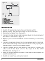
LW12
LW12
WALL LAMP
NINWALL
LAM
MODULE
MODULE
USER MANUAL
20486/20120530 • LW12 IN WALL LAMP MODULE
ALL RIGHTS RESERVED MARMITEK®
TM
2
© MARMITEK
INSTALLATION INSTRUCTIONS FOR MARMITEK
X-10 IN-WALL DIMMER MODULE LW12™
SAFETY WARNINGS
• The wiring of your electrical installation is live (230 V) and extremely
dangerous. Never connect the module when plugged into the
mains. Always turn off the main switch before starting the
installation.
• This product is for professional use and should be installed by a
certified installer.
• To prevent short circuits, this product should only be used inside and
only in dry spaces. Do not expose the components to rain or moisture.
Do not use the product close to a bath, swimming pool etc.
• Do not expose the components of your systems to extremely high
temperatures or bright light sources.
• Do not open the product: the device contains live parts. The
product should only be repaired or serviced by a qualified
repairman.
• In case of improper usage or if you have opened, altered and
repaired the product yourself, all guarantees expire. Marmitek does
not accept responsibility in the case of improper usage of the
product or when the product is used for purposes other than
specified. Marmitek does not accept responsibility for additional
damage other than covered by the legal product responsibility.
• This product is not a toy. Keep out of reach of children.
• Adapters: Only connect the adapter to the mains after checking
whether the mains voltage is the same as the values on the
identification tags. Never connect an adapter or power cord when
it is damaged. In that case, contact your supplier.
• Automatic switching devices provide comfort, but can also be
dangerous. They can surprise people or can ignite clothing hanging
over an electric heat source. Please be careful and take appropriate
measures to avoid accidents.
LW12
3
How does Marmitek X-10 work?
Marmitek X-10 components use the existing mains wiring to
communicate (using Marmitek X-10 signals). You can build a complete
system using the three different kind of components of the Marmitek
X-10 System:
1. Modules:
These components will receive Marmitek X-10 signals and will switch
or dim the attached lamp or appliance.
2. Controllers:
These components will transmit Marmitek X-10 signals and thus will
control the Modules.
3. Transmitters:
Wireless components like remotes. The signals of these components
will be received by a controller with transceiver functionality (IRRF 7243,
TM13 or console of a Marmitek Security System).
The Transceiver will translate the signals into Marmitek X-10 signals on
the power line.
Addresses
Up to a maximum of 256 different addresses can be preset. These are
subdivided into a so-called HouseCode (A to P incl.) and a UnitCode (1
to 16 incl.). The HouseCode can also be set on the controllers, so that
the controllers and modules become part of the same system. The
address can be set either using code dials or by pressing buttons,
depending on the type of module.
The Marmitek X-10 System uses standard commands, which control all
units with the same HouseCode at the same time (e.g. all lights on, all
off, etc.).
4
© MARMITEK
Signal Range
Range of Marmitek X-10 signals over the Power Line and how
to increase the range.
The Marmitek X-10 System is based on power line communication.
The range of the Marmitek X-10 signals very much depends on the
local circumstances. On average the range is a cable length of 80
meters.
If you have difficulties with the range of your Marmitek X-10
signals, please pay attention to the following facts:
1. When more than one phase is used for your electrical system, it is
necessary to couple these phases for the Marmitek X-10 signals. For
coupling you can use FD10 Phase Couplers/Filters. You only need to
install a Phase Coupler/Filter when your wall outlets and light
switches are divided over more than one phase (more than one
group is no problem). For bigger buildings or longer distances we
advice you to use an active repeater instead of passive FD10’s.
2. It is possible that Marmitek X-10 signals are attenuated by devices
and lights which are connected to the power line. In a normal home
situation this effect is negligible (the Marmitek X-10 system is using
active gain control to eliminate the effects). However, it is possible
that a particular device in your house is attenuating the signals so
much that the range of Marmitek X-10 signals is decreased
significantly. When you have range problems, it is wise to try to
locate the device which is attenuating the signals simply by
unplugging devices from the power line, and testing the differences
in range for your Marmitek system. When e.g. your conclusion is
that e.g. your computer monitor is attenuating the signal, you can
use a FM10 Plug-in Filter between the power line and the monitor
to eliminate the effects.
LW12
5
Known devices which can cause attenuation are:
PC Monitors
PCs with heavy internal power supplies
Old Televisions
Copiers
Fluorescent Lights
Gas Discharge Lamps (Energy Saving Lamps)
3. Some (old) devices are able to disturb the signal by transmitting
noise on the power line. Because the Marmitek X-10 signals are
transmitted on 120 kHz, only noise on or near this frequency will have
influence on the range. When you use a FM10 Filter to connect this
device to the power line, the noise will be filtered.
4. The Marmitek X-10 protocol has several mechanism to avoid
modules to be switched on or off by other sources than your
Marmitek X-10 Controllers. However, it is possible that the Marmitek
X-10 signals are disturbed by e.g. baby phones which are in TALK
mode (continuous transmission). When these kind of signals are
present on the power line it is possible that the Marmitek X-10 signals
will not come through.
5. The mains do not stop at the front door of your home. Everything
that is attached
to mains nearby your home can have influence on Marmitek X-10
signals (e.g. heavy machinery). If you think that your system is
influenced by devices out of your house, it is advisable to install FD10
Phase Coupler/Filter on each phase entering the house. These filters
will block signals coming into or going out of your house, but will
also match the impedance for the mains. The FD10’s will not only
filter but will also couple the phases (please see 1).
6
© MARMITEK
INTRODUCTION
Congratulations on your purchase of the LW12.
• The MicroModule can be installed behind conventional wall
switches or into wall outlets because of the extreme small size of
the MicroModule (Minimum built-in depth 40 mm, advised 50
mm). The MicroModule is also ideal for installation into light fixtures
or for use in areas with limited space such as rooms with lowered
ceilings.
• Universal compatibility: No limitation in choosing brand, colour or
type of any wall switches and outlets. The LW12 can be used to
switch and dim 230V light bulbs, 230V halogen lamps and lowvoltage halogen lamps with transformers ranging from 60 to 250
watts/230 volts.
This module can be activated using a momentary switch connected
to it or using Marmitek X-10 PLC signals. It can be operated using the
following Marmitek X-10 signals: ON, Off, DIM, BRIGHT and the
optional Marmitek X-10 commands All Lights On/All Lights Off/All
Units Off if these are programmed. The unit will accept a momentary
switch. The input for the switch is connected to the phase (brown
wire, 230V), the output of the switch is connected to input "K" of
the LW12 MicroModule. See figure A.
No Neutral (blue wire) has to be connected to the LW12
MicroModule, which means it can be easily used instead of a normal
switch, without additional wiring. The module is equipped with
softstart, softdim and a memory setting for the last dim level. When
power has been interrupted, the module will be in the OFF position.
The LW12 uses 1-way X-10 communication.
LW12
7
Figure A.
1.
2.
3.
4.
5.
6.
Lamp
Neutral (blue)
Live (brown)
Momentary Switch
Load (black)
Switch input (black)
INSTALLATION
•
•
•
•
•
Switch off appropriate mains fuse and master switch!
Where present, take the wall switch out of the wall box.
Disconnect all wires from the switch.
Connect the live (brown) and load wire (black) to the terminals of
the LW12 as described in figure A.
Replace your normal make/break contact switch by a momentary
switch.
Connect a load wire (brown) to the momentary switch (CAUTION:
In the interest of safety and to make the device work properly, this
load wire HAS TO be from the same group).
Connect a black wire to the output of the switch. Connect the
other end of this black wire to the input K of the LW12
MicroModule. See figure A.
Place the module against the back of the wall box and replace the
switch inside the box.
Switch on mains fuse and master switch.
8
© MARMITEK
•
•
•
•
Programming the address and the optional functions All
Lights On/All Lights Off/All Units Off:
Unlike most Marmitek X-10 Modules the LW12 does not have code
wheels.
When leaving the factory, the LW12 is set to the default address A1
en does not respond to the optional functions All Lights On/All Lights
Off/All Units Off. To change the address and the settings for the All
Lights On/All Lights Off/All Units Off functions, the module needs to
be set to the program mode.
Activating the program mode can be done in 2 ways:
1. By transmitting On / Off commands of the set address in quick
succession (e.g. if the address is B2: B2 ON, B2 OFF, B2 ON, etc.) After
the LW12 has changed state 5 times, with no more than 1.5 seconds
between changes, the LW12 will no longer respond, which means the
module is set to the program mode.
2. By quickly pressing/switching the momentary switch connected to
the module. After the LW12 has changed state 5 times, with no more
than 1.5 seconds between changes, the LW12 will no longer respond,
which means the module is set to the program mode. Once in
Program Mode the new address can be set by sending an "Address"
or "Address On" (e.g. B2 ON) or "Address Off" command for the
new address code twice (using any Marmitek X-10 controller). If you
want to change the code again, just send the new ‘Address ON’ or
‘Address OFF’ commando twice. To set the unit to respond to "All
Lights On" and/or "All Lights Off" and/or "All Units Off" just send
these commands twice for the new address code (using any X-10
controller).
Please note: The "All Lights On/All Lights Off /All Units Off" options
can be disabled by setting a new address or by returning to the
Default Setting.
LW12
9
Resetting the LW12
When leaving the factory, the LW12 is set to the default address A1
en does not respond to the optional functions All Lights On/All Lights
Off/All Units Off. If the address and settings for the options "All lights
on/All lights off /All Units Off" aren’t known, the default address of
A1 can be set by applying power to the unit and sending the address
P16 to the unit twice (using any X-10 controller - i.e.: TM13 + RF
remote control).
This can either be just the address "P16" or "P16 On" or "P16 Off".
The commands must be sent within 30 seconds of applying power to
the unit. Setting the default address automatically cancels the options
"All Lights On", "All Lights Off" or "All Units Off".
Exiting the programming mode
Automatic: Wait for 1 minute. The device will then automatically exit
the program mode. Manually: To return to Run Mode: either send
"Address On", "Address Off" or press the key quickly (no more than
1. 5 seconds between key presses). After 5 key presses or "On/Off"
commands, the LW12 will start to respond, indicating that the unit is
back in Run Mode.
Detailed information on the type of switch
If the connected momentary switch is used, the status of the LW12
will change if the button is pressed for less than 2 seconds. If the
momentary switch is pressed for a longer duration, the LW12 will dim.
The module first dims all the way down and then back up.
10
© MARMITEK
FREQENTLY ASKED QUESTIONS
What is the reason for modules to switch on/off spontaneously?
It is possible that a Marmitek X-10 System is installed at one of your
neighbours using the same House Code. To solve this problem try to
change the House Code of your system, or have FD10 Phase
Coupler/Filter installed at your incoming mains.
My modules will not respond to my controller.
Make sure that the House Code on all Modules and Controllers are
set to the same House Code (A .. P).
My modules will not react to my remote / sensor.
When you use a remote or sensor, you should have at least one TM13
Transceiver or Marmitek Security Console installed in your house.
These components will translate the radio signals to the Marmitek X10 signal on the power line. Only one Transceiver should be installed
for all remotes and sensors set to the same House Code.
Am I able to increase the range of my remotes by using more
Transceivers?
Yes, you can use more than one TM13 Transceiver in your home when
the range of your remotes is not sufficient. The TM13 is using so called
collision detection to prevent signals to be disturbed when more than
one TM13 is transmitting. TM13’s will wait for a quite power line
before transmitting their data. To prevent your Marmitek X-10 System
to become slow or to prevent dimming from becoming less smooth,
make sure that the TM13 units are placed as far away from each other
as possible.
LW12
11
If your lamp doesn’t work:
• Does the light work if you connect it directly to the mains?
• Is the module connected to a surge protector? A surge protector
might block signals from your interface or controller.
• Is the HouseCode set correctly?
Do you still have questions? Please check out
www.marmitek.com for more information.
TECHNICAL DATA
Supply voltage:
Supply current :
Making capacity:
Signal sensitivity:
Input impedance:
X-10 Key codes:
Connection:
Ambient temperature:
Dimensions:
230V - 50 Hz
< 20 mA capacitive
60W/230V to 250W/230V for incandescent
lamps and halogen light
15 mVpp min 50 mVpp max at 120 kHz
> 180 Ohm (L - N) at 120 kHz
All units Off, All Lights On, On, Off, Dim, Bright,
All Lights Off, extended code 1 type 3
Connecting clamps for phase, switched phase
and switch (neutral not required)
-10° C to + 40° C (operation)
-20° C to + 70° C (storage)
46x46x17mm
Environmental Information for Customers in the European Union
European Directive 2002/96/EC requires that the equipment bearing this symbol on the product
and/or its packaging must not be disposed of with unsorted municipal waste. The symbol
indicates that this product should be disposed of separately from regular household waste
streams. It is your responsibility to dispose of this and other electric and electronic equipment
via designated collection facilities appointed by the government or local authorities. Correct disposal and
recycling will help prevent potential negative consequences to the environment and human health. For more
detailed information about the disposal of your old equipment, please contact your local authorities, waste
disposal service, or the shop where you purchased the product.
12
© MARMITEK
DECLARATION OF CONFORMITY
Hereby, Marmitek BV, declares that this LW12 is in compliance with the essential
requirements and other relevant provisions of the following Directives:
Council Directive 89/336/EEC of 3 May 1989 on the approximation of the laws of the
Member States relating to electromagnetic compatibility
Council Directive 73/23/EEC of 19 February 1973 on the harmonization of the laws of
Member States relating to electrical equipment designed for use within certain voltage
limits
MARMITEK BV - PO. BOX 4257 - 5604 EG EINDHOVEN - NETHERLANDS
Copyrights
Marmitek is a trademark of Pattitude B.V., LW12 is a trademark of Marmitek BV. All rights reserved.
Copyright and all other proprietary rights in the content (including but not limited to model numbers,
software, audio, video, text and photographs) rests with Marmitek B.V. Any use of the Content, but
without limitation, distribution, reproduction, modification, display or transmission without the prior
written consent of Marmitek is strictly prohibited. All copyright and other proprietary notices shall be
retained on all reproductions.
LW12
13