1
®
Maintenance Manual
The Printronix P5000 series of Line Matrix Printers
The Printronix P5000 series of Line Matrix Printers
Maintenance Manual
®
164253-001, Rev D
Trademark Acknowledgements
Trademark Acknowledgements
ANSI is a registered trademark of American National Standards Institute, Inc.
Centronics is a registered trademark of Genicom Corporation.
Code V is a trademark of Quality Micro Systems.
Chatillon is a trademark of John Chatillon & Sons, Inc.
Dataproducts is a registered trademark of Dataproducts Corporation.
EIA is a registered service mark of Electronic Industries Association.
ENERGY STAR® is a registered trademark of the United States
Environmental Protection Agency. As an ENERGY STAR® Partner,
Printronix has determined that this product meets the ENERGY STAR®
guidelines for energy efficiency.
Ethernet is a trademark of Xerox Corporation.
IBM is a registered trademark of International Business Machines
Corporation.
IEEE is a registered trademark of the Institute of Electrical and Electronics
Engineers.
IGP is a registered trademark of Printronix, Inc.
Intelligent Printer Data Stream and IPDS are trademarks of International
Business Machines Corporation.
LinePrinter Plus is a registered trademark of Printronix, Inc.
MS-DOS is a registered trademark of Microsoft Corporation.
PC-DOS is a trademark of International Business Machines Corporation.
PGL is a registered trademark of Printronix, Inc.
PrintNet is a trademark of Printronix, Inc.
Printronix is a registered trademark of Printronix, Inc.
PSA is a trademark of Printronix, Inc.
QMS is a registered trademark of Quality Micro Systems.
RibbonMinder is a trademark of Printronix, Inc.
SureStak is a trademark of Printronix, Inc.
Torx is a registered trademark of Camcar/Textron Inc.
Utica is a registered trademark of Cooper Power Tools.
Warranty and Copyright Information
Printronix, Inc. makes no representations or warranties of any kind regarding
this material, including, but not limited to, implied warranties of
merchantability and fitness for a particular purpose. Printronix, Inc. shall not
be held responsible for errors contained herein or any omissions from this
material or for any damages, whether direct, indirect, incidental or
consequential, in connection with the furnishing, distribution, performance or
use of this material. The information in this manual is subject to change
without notice.
This document contains proprietary information protected by copyright. No
part of this document may be reproduced, copied, translated or incorporated
in any other material in any form or by any means, whether manual, graphic,
electronic, mechanical or otherwise, without the prior written consent of
Printronix, Inc.
All rights reserved.
COPYRIGHT © 1996, 1999, PRINTRONIX, INC.
Warranty and Copyright Information
Communication Notices
Federal Communications Commission (FCC) Statement: This equipment
has been tested and found to comply with the limits for a Class A digital
device, pursuant to Part 15 of the FCC Rules. These limits are designed to
provide reasonable protection against harmful interference when the
equipment is operated in a commercial environment. This equipment
generates, uses, and can radiate radio frequency energy and, if not installed
and used in accordance with the instruction manual, may cause harmful
interference to radio communications. Operation of this equipment in a
residential area is likely to cause harmful interference, in which case the user
will be required to correct the interference at his own expense.
Properly shielded and grounded cables and connectors must be used in order
to meet FCC emission limits. Printronix is not responsible for any radio or
television interference caused by using other than recommended cables and
connectors or by unauthorized changes or modifications to this equipment.
Unauthorized changes or modifications could void the user’s authority to
operate the equipment.
This device complies with Part 15 of the FCC Rules. Operation is subject to
the following two conditions: (1) this device may not cause harmful
interference, and (2) this device must accept any interference received,
including interference that may cause undesired operation.
Canadian Department of Communications Compliance Statement:
This Class A digital apparatus meets all requirements of the Canadian
Interference-Causing Equipment Regulations.
Avis de conformité aux normes du ministère des Communications du
Canada:
Cet appareil numérique de la classe A respecte toutes les exigences du
Règlement sur le matériel brouilleur du Canada.
European Union (EC) Electromagnetic Compatibility Directives: This
product is in conformity with the protection requirements of EC Council
Directive 89/336/EEC on the approximation of the laws of the Member States
relating to electromagnetic compatibility. Printronix cannot accept
responsibility for any failure to satisfy the protection requirements resulting
from a non-recommended modification of the product, including the fitting of
non-Printronix option cards.
Dieses Gerät ist berechtigt in Übereinstimmung mit dem deutschen EMVG
vom 9.Nov.92 das EG-Konformitätszeichen zu furhren.
Properly shielded and grounded cables and connectors must be used in order
to reduce the potential for causing interference to radio and TV
communication and to other electrical or electronic equipment.
This product has been tested and found to comply with limits for Class A
Information Technology Equipment according to CISPR 22/European
Standard EN 55022. The limits for Class A equipment were derived for
commercial and industrial environments to provide reasonable protection
against interference with licensed communication equipment.
Chapter
Communication Notices
Warning: This is a Class A product. In a domestic environment this product
may cause radio interference in which case the user may be required to take
adequate measures.
Dieses Gerät erfüllt die Bedingungen der EN 55022 Klasse A. Für diese
Klasse von Geräten gilt folgende Bestimmung nach dem EMVG:
Geräte dürfen an Orten, für die sie nicht ausreichend entstört sind, nur mit
besonderer Genehmigung des Bundesminesters für Post und
Telekommunikation oder des Bundesamtes für Post und Telekommunikation
betrieben werden. Die Genehmigung wird erteilt, wenn keine
elektromagnetischen Störungen zu erwarten sind.
(Auszug aus dem EMVG vom 9.Nov.92, Para.3, Abs.4)
Hinweis: Dieses Genehmigungsverfahren ist von der Deutschen Bundespost
noch nicht veröffentlict worden.
6
Table of Contents
1 Maintenance Overview......................... 11
About the Printer................................................................. 11
P5000 Printers .................................................................... 11
Kanji/Hanzi Printers...................................................... 11
Printer Evolution ........................................................... 12
How to Identify the Printer ............................................ 12
Important Maintenance Notes............................................. 15
About This Manual.............................................................. 15
How to Use This Manual .............................................. 16
Notes and Notices ........................................................ 16
Printing Conventions in This Manual............................ 16
Safety Notices..................................................................... 17
Hinweise zur Sicherheit ...................................................... 17
Controls and Indicators....................................................... 18
Tools, Test Equipment, and Supplies ................................. 24
2 Preventive Maintenance....................... 25
Cleaning the Printer ............................................................ 25
Cleaning the Outside Surfaces ........................................... 25
Cleaning the Shuttle Frame Assembly ............................... 27
Cleaning the Card Cage Fan Assembly ............................. 28
3 Troubleshooting ................................... 29
Introduction ......................................................................... 29
Troubleshooting Aids .......................................................... 29
Start Here... ........................................................................ 30
Troubleshooting Display Messages.................................... 31
How to Clear LCD Messages ....................................... 31
Troubleshooting Other Symptoms ...................................... 36
Troubleshooting Procedures............................................... 38
How to Use the Troubleshooting Procedures............... 38
The Procedures............................................................ 39
Communications Failures ................................................... 88
Diagnostic Printer Tests...................................................... 89
Selecting and Running Diagnostic Printer Tests .......... 90
Boot Diagnostics Menu....................................................... 92
vii
Table of Contents
Hex Code Printout .............................................................. 95
How to Print a Hex Dump............................................. 96
ASCII Character Set ........................................................... 97
Soft vs. Hard Reset............................................................. 98
The Power On Sequence ................................................... 99
CMX Controller Board Handshake Sequences ............ 99
DC Software Initialization and Power Up ................... 103
4 Adjustment Procedures ..................... 105
Introduction ....................................................................... 105
Preparing the Printer for Maintenance.............................. 106
Returning the Printer to Normal Operation ....................... 107
Belt, Paper Feed Timing, Adjustment (Figure 10) ............ 108
Belt, Platen Open, Adjustment (Figure 11) ....................... 110
Paper Drive Motor Pulley Alignment (Figure 12) .............. 112
Paper Scale Alignment (Figure 13)................................... 114
Platen Gap Adjustment (Figure 14) .................................. 116
Platen Open Motor Pulley Alignment (Figure 15) ............. 118
Ribbon Guide Alignment (Figure 16) ................................ 120
Splined Shaft Skew Adjustment (Figure 17) ..................... 122
Paper Out Adjustment ...................................................... 124
Hammer Phasing Adjustment ........................................... 128
Loading Flash Memory from One Diskette ....................... 130
Loading Flash Memory from Multiple Diskettes................ 135
Set Shuttle Speed............................................................. 141
5 Replacement Procedures
and Illustrated Parts Lists ....................... 143
Organization of This Chapter............................................ 143
Section I: Replacement Procedures ................................. 144
List of Removal/Installation Procedures ..................... 144
Belt, Paper Feed Timing ............................................ 146
Belt, Platen Open ....................................................... 147
Circuit Breaker ........................................................... 148
Connector Shells ........................................................ 149
Connector Stiffening Clips.......................................... 151
Control Panel Assembly, Cabinet Models .................. 153
Control Panel Assembly, Pedestal Models ................ 154
Controller Board (CMX).............................................. 155
Cover Assembly, Hammer Bank / Ribbon Mask ........ 157
Cover Assembly, Shuttle ............................................ 160
Cover Assembly, Top, Pedestal Models .................... 161
viii
Table of Contents
Expansion-CT ............................................................ 162
Fan Assembly, Cabinet Exhaust ................................ 163
Fan Assembly, Card Cage ......................................... 164
Fan Assembly, Hammer Bank.................................... 165
Hammer Spring Assembly.......................................... 166
Magnetic Pickup (MPU) Assembly ............................. 170
Memory Modules and Security PAL ........................... 171
Paper Feed Motor ...................................................... 174
Paper Ironer ............................................................... 176
Paper Path ................................................................. 177
Platen ......................................................................... 178
Platen Open Motor ..................................................... 182
Power Supply Board .................................................. 184
PrintNet Ethernet Interface Assemblies ..................... 185
10Base2 and 10Base-T LEDs and DIP Switches ...... 186
10/100Base-T LEDs and Dipswitches........................ 188
Resistors, Terminating ............................................... 190
Ribbon Drive Motor .................................................... 192
Ribbon Guide Assembly (L/R).................................... 193
Ribbon Hub ................................................................ 194
Shaft, Splined ............................................................. 195
Shaft, Support ............................................................ 197
Shuttle Frame Assembly ............................................ 198
Spring Assembly, Gas................................................ 200
Spring, Extension, Hammer Bank .............................. 201
Switch Assembly, Paper Detector .............................. 202
Switch Assembly, Platen Interlock ............................. 203
Tractor (L/R) ............................................................... 204
Section II: Illustrated Parts Lists ....................................... 205
Illustrations of Printer Components ............................ 205
6 Principles of Operation ...................... 239
Line Matrix Printing ........................................................... 239
Printing Rates ................................................................... 242
Printing Mechanism .......................................................... 242
Shuttle Frame Assembly ............................................ 243
Paper Transport System ............................................ 245
Ribbon Transport System........................................... 246
Logical Control of the Printer ............................................ 247
Control Panel .................................................................... 248
CMX Controller Board....................................................... 249
Data Controller ........................................................... 251
ix
Table of Contents
Engine Controller ....................................................... 254
Power Supply Board ......................................................... 255
AC Power ................................................................... 255
DC Power ................................................................... 256
Printer Interface ................................................................ 256
Graphics ........................................................................... 257
A Wire Data............................................. 259
B Abbreviations &
Signal Mnemonics ................................... 299
C Metric Conversion Tables ................. 307
D Noise Suppression Devices .............. 309
E SureStak™ Power Stacker ................ 311
Contents ........................................................................... 311
Introduction ....................................................................... 311
Removing the Power Stacker ........................................... 312
Installing the Power Stacker ............................................. 317
Replacing the Constant Force Spring............................... 328
Replacing the Timing Belts ............................................... 331
Illustrated Parts Breakdown.............................................. 335
x
1
Maintenance Overview
About the Printer
Printronix P5000 series line matrix printers use PSA (Printronix System
Architecture), which puts all data control and printer control logic on one
circuit board. The use of flash memory on this board permits rapid access to
stored printer emulations and fast processing of print data. A variable-speed
shuttle and half-step paper control enable these printers to print a wide variety
of high-volume jobs with minimum maintenance and maximum reliability.
Although technologically advanced, the P5000 printer is easy to use. The
operator can select every printer function at the printer control panel or by
sending control codes in the data stream from the host computer to the
printer. For greater security and to protect special printer configurations, the
operator can program which key combination locks and unlocks the ENTER
key on the control panel.
This is also an excellent graphics printer, with optional features that simplify
the creation of images. The IGP and Code V Printronix emulations, for
example, are simple but versatile graphics programming languages that load
into flash memory.
P5000 Printers
The P5000 family consists of machines that print at different speeds. (See
Table 1.) Many models are available in either a floor cabinet or pedestal
housing. P5XKA (Kanji/Hanzi) models are available in pedestal, cabinet, or
“table top” configuration. Despite its name, the table top P5XKA printer is not
intended for use on a table. It is really a pedestal model printer that has been
removed from the pedestal and packaged separately to facilitate shipping to
certain international markets. A “table top” printer is then installed on its
pedestal after it arrives at its destination.
Kanji/Hanzi Printers
P5XKA printers have shuttle assemblies, hammer springs, and software
modified to print the Kanji/Hanzi character sets used in Asia. These printers
support the GB Song and GB Kai character sets used in the People’s
Republic of China, Singapore, and Hong Kong, and the Big-5 Ming character
set used in Hong Kong and Taiwan. P5XKA printers can mix ASCII and Kanji/
Hanzi characters on the same line, with ASCII characters occupying half the
width of Kanji/Hanzi character cells. Because of the density and complexity of
these character sets, these models print at lower speeds.
11
Chapter
1
P5000 Printers
Printer Evolution
The newest models in the family are the P5X05B, P5X10, and P5X15, which
are available both in pedestal and floor cabinet housings. These models have
a redesigned shuttle frame assembly, hammer bank, and ribbon guides. The
new shuttle and hammer bank assemblies are not compatible with earlier
P5000 printers, but the new ribbon guides can be used on any model P5000
printer.
The P5X05B, P5X10, and P5X15 models also use the CMX 040 controller
board, which has a 40 MHz clock speed for the Data Controller unit. The CMX
040 can be used in any P5000 printer, but the P5X05B, P5X10, and P5X15
models cannot use earlier versions of the CMX board.
When you replace components, be careful to order the correct spares for the
model you are servicing. The next section explains how to identify a P5000
series printer.
How to Identify the Printer
A P5000 printer is identified by its model number. The model number is a
code that indicates the printer type, family, speed, and housing. Figure 1
shows how to interpret a model number.
Table 1 lists the models comprising the P5000 family. The speeds listed in
Table 1 are the highest speeds attainable under controlled conditions. Actual
printing speed is determined by the interaction of many variables. For more
information about printing speeds, refer to “Printing Rates” on page 242.
Printronix Line
Matrix Printer
Housing Code:
0 = Pedestal
1 = Table Top
2 = Floor Cabinet
Optional 12 MIL (0.012 inch) hammer
tips. Standard tips are 16 MIL (0.016
inch). This option does not apply to Kanji/
Hanzi printers, which have unique
hammer spring assemblies.
P5005-12-QA
P5000 Printer
QA = Pedestal model with optional QuickAccess Cover
SS = Cabinet model with optional SureStak™
power paper stacker.
Speed Rating:
05 = 475 lpm
05A = 500 lpm
05B = 500 lpm (40 MHz CMX board)
08 = 800 lpm
09 = 900 lpm
10 = 1000 lpm
12 = 1200 lpm
14 = 1400 lpm
15 = 1500 lpm
KA = Kanji/Hanzi printer
Figure 1. How to Interpret Model Numbers
12
How to Identify the Printer
Table 1. P5000 Printers
Data
Controller
Clock Speed1
Print
Speed
Enclosure
Hammer Bank
P50KA
585 lpm
Pedestal
91 Hammers
Kanji / Hanzi
25 MHz
P5005
475 lpm
Pedestal
28 Hammers
25 MHz
P5005-QA
475 lpm
Pedestal w/QuickAccess Cover
28 Hammers
25 MHz
P5005-12
475 lpm
Pedestal
28 Hammers,
12 MIL tips
25 MHz
P5005-12-QA
475 lpm
Pedestal w/QuickAccess Cover
28 Hammers,
12 MIL tips
25 MHz
P51KA
585 lpm
Table Top
91 Hammers
Kanji / Hanzi
25 MHz
P5205
475 lpm
Cabinet
28 Hammers
25 MHz
P5205-12
475 lpm
Cabinet
28 Hammers,
12 MIL tips
25 MHz
P5005A
500 lpm
Pedestal
28 Hammers
25 MHz
P5005A-QA
500 lpm
Pedestal w/QuickAccess Cover
28 Hammers
25 MHz
P5005A-12
500 lpm
Pedestal
28 Hammers,
12 MIL tips
25 MHz
P5005A-12-QA
500 lpm
Pedestal w/QuickAccess Cover
28 Hammers,
12 MIL tips
25 MHz
P5205A
500 lpm
Cabinet
28 Hammers
25 MHz
P5205A-12
500 lpm
Cabinet
28 Hammers,
12 MIL tips
25 MHz
P5005B
500 lpm
Pedestal
28 Hammers
40 MHz
P5005B-QA
500 lpm
Pedestal w/QuickAccess Cover
28 Hammers
40 MHz
P5005B-12
500 lpm
Pedestal
28 Hammers,
12 MIL tips
40 MHz
P5005B-12-QA
500 lpm
Pedestal w/QuickAccess Cover
28 Hammers,
12 MIL tips
40 MHz
P5205B
500 lpm
Cabinet
28 Hammers
40 MHz
Model Number
13
Chapter
1
P5000 Printers
Table 1. P5000 Printers
Data
Controller
Clock Speed1
Print
Speed
Enclosure
Hammer Bank
P5205B-12
500 lpm
Cabinet
49 Hammers,
12 MIL tips
40 MHz
P5008
800 lpm
Pedestal
49 Hammers
25 MHz
P5008-QA
800 lpm
Pedestal w/QuickAccess Cover
49 Hammers
25 MHz
P5208
800 lpm
Cabinet
49 Hammers
25 MHz
P500
900 lpm
Pedestal
49 Hammers
25 MHz
P5009-QA
900 lpm
Pedestal w/QuickAccess Cover
49 Hammers
25 MHz
P5209
900 lpm
Cabinet
49 Hammers
25 MHz
P5010
1000 lpm
Pedestal
60 Hammers
40 MHz
P5010-QA
1000 lpm
Pedestal w/QuickAccess Cover
60 Hammers
40 MHz
P5210
1000 lpm
Cabinet
60 Hammers
40 MHz
P5212
1200 lpm
Cabinet
91 Hammers
25 MHz
P5214
1400 lpm
Cabinet
91 Hammers
40 MHz
P5214-SS
1400 lpm
Cabinet
w/SureStak
Paper Stacker
91 Hammers
40 MHz
P5015
1500 lpm
Pedestal
102 Hammers
40 MHz
P5015-QA
1500 lpm
Pedestal w/QuickAccess Cover
102 Hammers
40 MHz
P5215
1500 lpm
Cabinet
102 Hammers
40 MHz
P5215-SS
1500 lpm
Cabinet
w/SureStak
Paper Stacker
102 Hammers
40 MHz
P52KA
585 lpm
Cabinet
91 Hammers
Kanji / Hanzi
40 MHz
Model Number
1
The microprocessor of the Data Controller unit on the CMX controller board runs at 25
MHz or 40 MHz, depending on printer model. This means there are two kinds of CMX
controller board for these printers, used as indicated in Table 1. The 40 MHz controller
board, however, is compatible with all models that use the 25 MHz board and should be
used if the CMX board is replaced.
14
How to Identify the Printer
Important Maintenance Notes
To ensure the best performance of the printer, remember these maintenance
principles whenever you service the printer.
CAUTION
Failure to observe these guidelines can result in damage to the
equipment.
•
Do not adjust the platen gap unless
1) the original shuttle frame assembly or platen has been replaced with a
new or rebuilt unit, or
2) you are instructed to do so in a troubleshooting procedure.
•
Never bend or tweak hammer springs. Always handle hammer springs by
the thick mounting base. The hammer springs and hammer tips are
delicate and precisely aligned.
•
Use only the ribbons specified in Appendix B. Use of incorrect ribbons
can lead to ink migration problems, degraded print quality, and expensive
damage to the printer.
•
Do not close the forms thickness lever too tightly. Closing the forms
thickness lever too tightly can lead to smearing, degraded print quality,
paper jams, and damage to the platen and shuttle assembly.
About This Manual
This is a field service maintenance manual. It is designed so that you can
locate maintenance information quickly.
This manual does not explain how to install, operate, or configure the printer.
That information is in the User’s Manual.
This manual does not explain how to program application software for
operation with the printer. Programming information for the protocols used by
the printer is in the appropriate programmer’s reference manual:
•
LinePrinter Plus Programmer’s Reference Manual
Defines host control codes for the LinePrinter Plus emulations.
•
Character Sets Reference Manual
Information about and examples of the character sets available in
Printronix line matrix printers.
•
Network User’s Manual
Information about network protocols, configuration, and network
operation.
•
Coax/Twinax Programmer’s Reference Manual
Defines host control codes and character sets for the optional coax/twinax
emulations.
•
ANSI Programmer’s Reference Manual
Defines host control codes and character sets for the ANSI emulation.
•
IPDS Twinax Emulation Programmer’s Reference Manual
An overview of Intelligent Printer Data Stream™ (IPDS) features,
commands, and diagnostics.
15
Chapter
1
About This Manual
•
IGP/PGL Programmer’s Reference Manual
Describes the optional IGP Printronix emulation. The IGP Printronix
emulation allows the user to create and store forms; generate logos, bar
codes, and expanded characters; create other graphics, and merge
graphics with alphanumeric data as a document is printed.
•
IGP/VGL Programmer’s Manual
Describes the optional Code V Printronix emulation. The Code V
Printronix emulation allows the user to create and store forms; generate
logos, bar codes, and expanded characters; create other graphics, and
merge graphics with alphanumeric data as a document is printed.
How to Use This Manual
1. Find the procedure or information you need in the Table of Contents or
the Index.
2. Read the entire procedure before you work on the printer.
3. Gather the parts and tools you will need.
4. Make sure you understand all safety notices before you start a task. (See
below.)
Notes and Notices
For your safety and to protect valuable equipment, read and comply with all
information highlighted under notes and notices. The heading of a notice
indicates the kind of information it contains:
WARNING
CAUTION
IMPORTANT
Conditions that could hurt you and damage equipment.
Conditions that could damage equipment.
Information vital to proper operation and maintenance of the printer.
NOTE: Notes contain tips for efficient operation, maintenance, and
troubleshooting.
IMPORTANT
The Safety Notices on page 17 apply at all times when you are working
on the printer. Please read them now.
Printing Conventions in This Manual
Control panel keys and indicators are highlighted in UPPERCASE BOLD
PRINT.
Example: Press the CANCEL key, then press the ON LINE key.
LCD (Liquid Crystal Display) messages are set off by quotation marks (“ “).
Example: Press the ON LINE key. “OFF LINE” appears on the LCD.
Control panel key combinations are indicated by the + (plus) symbol.
Example: Press = + >.
means Press the =(UP) key and the >(DOWN) key at the same time.
16
Printing Conventions in This Manual
Safety Notices
WARNING
Always disconnect the AC power cord from the printer or power source
before performing any maintenance procedure. Failure to remove power
could result in injury to persons or damage to equipment. If you must
apply power during maintenance, you will be instructed to do so in the
maintenance procedure.
WARNING
Always disconnect the AC power cord before cleaning the printer.
WARNING
To prevent injury from electric shock, wait at least one minute after
shutting off power before removing the power supply circuit board.
Wear a properly grounded static wrist strap when handling the power
supply board. Handle the board by the sides. Do not touch components
or flex the board during removal/installation.
WARNING
Over time, the upper edge of the paper ironer can become sharp. To
avoid cutting yourself, handle the paper ironer on the sides.
WARNING
Hold the printer cover securely while disengaging the gas spring
assembly.
Hinweise zur Sicherheit
VORSICHT
Bevor Sie anfällige Wartungsarbeiten durchführen, müssen Sie zuerst
immer das Netzkabel aus der Steckdose ziehen. Wird das Netzkabel
nicht herausgezogen, können Verletzungen oder Geräteschäden
entstehen. Falls die Wartungsarbeit Stromzufuhr erfordert, wird im
Wartungsablauf darauf hingewiesen.
VORSICHT
Ziehen Sie das Netzkabel aus der Steckdose, bevor Sie den Drucker
reinigen.
VORSICHT
Um Verletzungen durch Elektroschocks zu vermeiden, warten Sie
mindestens eine Minute nach Stromausschaltung, bevor Sie die
elektrische Schaltkarte entfernen. Bitte immer einen geerdeten,
statischen Handgelenkriemen tragen, wenn Sie die elektrische
Schaltkarte handhaben. Halten Sie die Karte nur an den seitlichen
Auswurfshebeln. Während des Herausnehmens/Installierens dürfen die
Komponenten der Karte nicht berührt oder gebogen werden.
VORSICHT
Die obere Kante der Papierschiene wird mit der Zeit scharf. Halten Sie
die Schiene deshalb an den Seiten, damit Sie sich nicht schneiden.
VORSICHT
Behalten Sie die Druckerabdeckung sicher im Griff, wenn Sie das
Gasfederpaket entfernen.
17
Chapter
1
Controls and Indicators
Controls and Indicators
Electrical Controls and Indicators, Cabinet Models (Figure 2)
Switch or
Indicator
Active
On-line
Active
Off-line
On when the printer is on-line, off when the printer is off-line. Flashes to indicate a
fault or warning.
ä
ä
Liquid Crystal Display. Displays printer status messages, fault messages, and
menus which permit user to set various configurations.
ä
ä
ON LINE/
CLEAR
Toggles the printer on-line and off-line. Clears the printer after a fault is corrected
and returns the printer to off-line state.
ä
ä
PAPER
ADVANCE
Prints any data in the buffer then moves paper up one line at the currently active
line spacing. If pressed longer than 1/2 second, moves paper to the next Top Of
Form as defined by the currently active form length.
ä
ä
VIEW /
EJECT
Moves the current print position to the tractor area for viewing. When paper is in
VIEW position, “Printer in View” displays and microstep adjustment feature is
active. (See UP and DOWN keys.) Holding key down for more than 1/2 second
invokes EJECT and paper is advanced two pages. (EJECT can be disabled via
the menus.) Pressing key a second time moves paper back to the print position
from either VIEW or EJECT position.
ä
ä
Power Switch
Status
Indicator
LCD
CANCEL
Function
Turns printer on and off: 1 = on, 0 = off. This switch is also a circuit breaker.
ä
Clears all data from the print buffer (if enabled in the MAINT/MISC menu).
= (UP)
Displays next higher level of a configuration menu. In VIEW mode, moves paper
up 1/72 inch. (See VIEW / EJECT key.)
ä
ä
> (DOWN)
Displays next lower level of a configuration menu. In VIEW mode, moves paper
down 1/72 inch. (See VIEW / EJECT key.)
ä
ä
< (NEXT)
Displays the next option in a configuration menu.
ä
; (PREV)
Displays the previous option in a configuration menu.
ä
SET TOF
Moves paper downward from TOF alignment mark to the print station and sets this
as the first line of print on a page, independent of forms length. If there are data in
the buffers, the printer slews to the page position where printing left off and prints
the data.
ä
PRT CONFIG
Prints the current printer configuration.
ä
JOB SELECT
Allows fast selection of any stored configuration. Repeated pressing scrolls
through all saved configurations. Press ENTER to select the displayed
configuration. (ENTER does not have to be unlocked for this function.)
ä
Enters an option displayed on the LCD into printer non-volatile memory. Starts and
stops printer tests, sets a value, or prints the configuration. This key is locked and
unlocked by a user-selectable key combination. (Refer to the User’s Manual.)
ä
ENTER
;+<
18
Resets the printer by reloading the power-up configuration and resetting the
internal state.
Printing Conventions in This Manual
(Off) (On)
Power Switch
Status Indicator
Raise printer
cover to use
these keys.
SET TOF
UP
PRT CONFIG
LCD
NEXT
PREV
JOB SELECT
PAPER
ON LINE ADVANCE
DOWN
VIEW
CANCEL
ENTER
CLEAR
EJECT
Figure 2. Electrical Controls, Cabinet Models
19
Chapter
1
Controls and Indicators
Electrical Controls and Indicators, Pedestal Models (Figure 3)
Switch or
Indicator
Active
On-line
Active
Off-line
On when the printer is on-line, off when the printer is off-line. Flashes to indicate a
fault or warning.
ä
ä
Liquid Crystal Display. Displays printer status messages, fault messages, and
menus which permit user to set various configurations.
ä
ä
ON-LINE
CLEAR
Toggles the printer on-line and off-line. Clears the printer after a fault is corrected
and returns the printer to off-line state.
ä
ä
PAPER
ADVANCE
Prints any data in the buffer then moves paper up one line at the currently active
line spacing. If pressed longer than 1/2 second, moves paper to the next Top Of
Form as defined by the currently active form length.
ä
ä
VIEW
EJECT
Moves the current print position to the tractor area for viewing. When paper is in
VIEW position, “Printer in View” displays and microstep adjustment feature is
active. (See UP and DOWN keys.) Holding key down for more than 1/2 second
invokes EJECT and paper is advanced two pages. (EJECT can be disabled via
the menus.) Pressing key a second time moves paper back to the print position
from either VIEW or EJECT position.
ä
ä
Power Switch
Status
Indicator
LCD
CANCEL
Function
Turns printer on and off: 1 = on, 0 = off. This switch is also a circuit breaker.
ä
Clears all data from the print buffer (if enabled in the MAINT/MISC menu).
↑
UP
Displays next higher level of a configuration menu. In VIEW mode, moves paper
up 1/72 inch. (See VIEW / EJECT key.)
ä
ä
↓
DOWN
Displays next lower level of a configuration menu. In VIEW mode, moves paper
down 1/72 inch. (See VIEW / EJECT key.)
ä
ä
→
NEXT
Displays the next option in a configuration menu.
ä
←
PREV
Displays the previous option in a configuration menu.
ä
Moves paper downward from TOF alignment mark to the print station and sets this
as the first line of print on a page, independent of forms length. If there are data in
the buffers, the printer slews to the page position where printing left off and prints
the data.
ä
PRT
CONFIG
Prints the current printer configuration.
ä
JOB
SELECT
Allows fast selection of any stored configuration. Repeated pressing scrolls
through all saved configurations. Press ENTER to select the displayed
configuration. (ENTER does not have to be unlocked for this function.)
ä
ENTER
Enters an option displayed on the LCD into printer non-volatile memory. Starts and
stops printer tests, sets a value, or prints the configuration. This key is locked and
unlocked by a user-selectable key combination. (Refer to the User’s Manual.)
ä
←+→
Resets the printer by reloading the power-up configuration and resetting the
internal state.
SET
TOF
20
Printing Conventions in This Manual
(Off) (On)
Power Switch
PREV
LCD
NEXT
PREV
UP
DOWN
SET
TOF
SET
TOF
NEXT
UP
PRT
CONFIG
JOB
PRT
CONFIG SELECT
JOB
SELECT
ENTER
ENTER
DOWN
Status Indicator
ON-LINE
CLEAR
PAPER
ADVANCE
ON-LINE
CLEAR
PAPER
ADVANCE
VIEW
EJECT
VIEW
EJECT
CANCEL
CANCEL
Figure 3. Electrical Controls, Pedestal Models
21
Chapter
1
Controls and Indicators
Mechanical Controls and Indicators, All Models (Figure 6)
Control or
Indicator
Function
Forms Thickness
Lever
Sets the platen for paper and forms of different
thicknesses. Lever must be fully opened (raised) to
load or unload paper.
Paper Supports
Help prevent paper jams by supporting inner sections
of paper. They are positioned manually by sliding
them along the shafts.
Forms Thickness
Pointer and Scale
Indicates relative thickness of forms and paper. Set
this lever at A for thin (single-part) forms, B for thicker
forms, and so on.
Tractors (2)
Hold and feed paper. Used to set side margin and
position paper horizontally.
Tractor Locks (2)
Lock tractors in position.
Horizontal
Adjustment Knob
Allows fine positioning of left print margin. Moves
paper and tractors left or right.
Vertical Position
Knob
Used to set top of form or first line to be printed.
Rotate this knob to move paper vertically. Works
when forms thickness lever is open.
Ribbon Loading
Path Diagrams
Instructions showing how to load the ribbon correctly.
One diagram is cast in relief on the shuttle cover, and
another is printed on the paper scale.
Paper Scale
A horizontal scale graduated in tenths of an inch,
useful for setting paper margins counting text
columns. (See below.)
1 inch
1
10
0.1 inch
22
20
Column
Number
Printing Conventions in This Manual
Paper
Supports
Left Tractor
Horizontal
Adjustment
Knob
Right Tractor
Tractor Lock
Tractor Lock
Vertical
Position
Knob
Ribbon Loading
Path Diagrams
Forms Thickness
Lever and Scale
Forms
Thickness
Pointer
Figure 4. Mechanical Controls and Indicators, All Models
23
Chapter
1
Tools, Test Equipment, and Supplies
Tools, Test Equipment, and Supplies
For field level maintenance of the printer, you will need these tools:
Adapter, 1/4 in. hex to 1/4 in. square, Utica HW-18
Alcohol, anhydrous
Allen Wrench, 1/16 inch
Allen Wrench, 3/32 inch
Allen Wrench, 7/64 inch
Allen Wrench, 5/64 inch
ESD Wrist Strap
Feeler Gauge, .010 inch
Feeler Gauge, .011 inch
Feeler Gauge, .040 inch
Force Gauge, (Chatillon NY, Gauge-r, 0-20 lb., CAT 719-20)
Hex bit, 3/16 in., torque screwdriver
Hex bit, 3/32 in., torque screwdriver
Hex bit, 5/32 in., torque screwdriver
Hex bit, 5/64 in., torque screwdriver
Lubricant, Bearing (Printronix P/N 101805-001)
Nut Driver, 1/4 inch
Nut Driver, 5/16 inch
Nut Driver or Open End Wrench, 7/32 inch
Open End Wrench, 5/16 inch
Pliers, Grip Ring, External
Screwdriver, flat tip
Screwdriver, Phillips, #1
Screwdriver, Phillips, #2
Screwdriver, Torque, Utica TS-35
Tie Wraps, 4 inch
Torx T-10 Driver
24
2
Preventive Maintenance
Cleaning the Printer
The printer is designed to require very little maintenance. Aside from normal
replenishment of paper and ribbons, the only preventive maintenance
required is periodic cleaning.
Because operating conditions vary widely, the user must determine how often
to clean the printer.
Since there is no guarantee that the user will clean the printer regularly, you
should clean the printer whenever you are called to service it. The cleaning
procedures in this chapter pertain to all models.
WARNING
CAUTION
Always disconnect the AC power cord before cleaning the printer.
Do not use abrasive cleaners, particularly on the window.
Do not drip water into the printer. Damage to the equipment will result.
Do not spray directly onto the printer when using spray solutions. Spray
the cloth, then apply the dampened cloth to the printer.
Do not vacuum the circuit boards.
Cleaning the Outside Surfaces
1. Power off the printer.
2. Disconnect the AC power cord from the printer or the power source.
3. Remove paper and the ribbon.
4. Dampen a clean, lint-free cloth with water and a mild detergent or with
window cleaning solution. The cloth must be damp, not wet. Wipe down
the outside surfaces of the printer.
5. Dry the outside surfaces with a clean, lint-free cloth.
6. Open the printer cover.
7. Using a soft-bristled, non-metallic brush (such as a toothbrush), brush
paper dust and ribbon lint off the tractors, shuttle cover assembly, base
casting, and ribbon guides. Vacuum up the residue. (See Figure 5.)
8. Wipe the splined shaft with a soft cloth.
CAUTION
To avoid corrosion damage, use only alcohol when cleaning printer
mechanical elements, and make sure the cleaning solution contains no
water.
25
Chapter
2
Cleaning the Outside Surfaces
9. Using a cloth dampened (not wet) with alcohol, clean the ribbon guides.
10. Vacuum up dust and residue from the lower cabinet.
11. Wipe the interior of the lower cabinet with a clean, lint-free cloth
dampened with water and a mild detergent or window cleaning solution.
12. Dry the cabinet interior with a clean, lint-free cloth.
13. Clean the shuttle frame assembly, as described in the next section.
4
3
2
1
NOTE: Cabinet model
shown. Procedure is the
same for pedestal model.
5
6
Legend:
1)
2)
3)
4)
5)
6)
Base Casting
Shuttle Cover Assembly
Splined Shaft
Tractors
Forms Thickness Lever
Ribbon Guide
Figure 5. Cleaning Inside the Cabinet or Top Cover
26
Cleaning the Shuttle Frame Assembly
1. Remove the shuttle cover assembly (page 160).
2. Remove the shuttle frame assembly (page 198).
3. Remove the paper ironer (page 176).
WARNING
Over time, the upper edge of the paper ironer can become sharp. To
avoid cutting yourself, handle the paper ironer on the sides.
4. Moisten a clean, soft cloth with alcohol. Wipe the paper ironer to remove
lint, ink, and paper residue.
5. Install the paper ironer (page 176).
6. Remove the hammer bank / ribbon mask cover assembly (page 157).
CAUTION
The ribbon mask is thin and easily bent. Be careful not to crease or kink
the ribbon mask when handling and cleaning it.
7. Moisten a clean, soft cloth with alcohol. Wipe the hammer bank cover and
ribbon mask to remove lint, ink, and paper residue. Clean the holes in the
cover strips. Carefully wipe between the hammer bank cover and the
ribbon mask (early models).
CAUTION
Do not use any solvents or liquids to clean the hammer tips. Clean the
hammer tips gently—too much pressure can chip them.
8. Using a stiff, non-metallic brush (such as a toothbrush), gently brush the
hammer tips to remove lint and ink accumulations. (See Figure 6.)
Vacuum up any residue.
NOTE: P5005 hammer bank is
shown. Procedure is the same
for all hammer banks.
1
Legend:
1)
Hammer Tip
Figure 6. Cleaning the Hammer Tips
CAUTION
The hammer bank contains a strong magnet. To prevent damage to the
hammer tips, do not let the hammer bank cover assembly snap into
place as the hammer bank magnet attracts it. Any impact of the cover
against the hammer bank can break hammer tips.
9. Install the hammer bank / ribbon mask cover assembly (page 157).
10. Install the shuttle frame assembly (page 198).
27
Chapter
2
Cleaning the Card Cage Fan Assembly
11. Install the shuttle cover assembly (page 160).
12. Clean the card cage fan assembly, as described in the next section.
Cleaning the Card Cage Fan Assembly
1. Cabinet Models: Remove the paper path (page 177).
Pedestal Models: Remove the top cover assembly (page 161).
2. Vacuum the card cage fan assembly and surrounding areas to remove
paper particles, dust, and lint. (See Figure 7.)
3. Cabinet Models: Install the paper path (page 177)
Pedestal Models: Install the top cover assembly (page 161).
4. Return the printer to normal operation (page 107).
NOTE: Cabinet model shown.
Procedure is the same for
pedestal model.
1
Legend:
1)
Card Cage Fan Assemb.y
Figure 7. Cleaning the Card Cage Fan Assembly
28
3
Troubleshooting
Introduction
This chapter lists fault messages and symptoms, and provides procedures for
troubleshooting printer malfunctions.
Always have the User’s Manual handy when you troubleshoot because this
manual does not cover printer operation or configuration. You must operate
the printer to check its performance, and sometimes you may have to
reconfigure it.
Troubleshooting Aids
Troubleshooting is faster and more effective if you understand the equipment
and make use of all available tools.
This manual provides a number of troubleshooting aids to help you isolate
printer malfunctions:
•
•
•
•
•
•
•
•
•
•
•
“Start Here” Logic Tree
page 30
Troubleshooting Display Messages
page 31
Message List
page 31
Troubleshooting Other Symptoms
page 36
General Symptom List
page 36
Troubleshooting Procedures
page 38
Diagnostic Printer Tests
page 92
Hex Code Printout
page 95
ASCII Character Set
page 97
The Power On Sequence
page 99
Appendix A: Wire Data
page 259
29
Chapter
3
Start Here...
Start Here...
Are you here because of an
error message?
YES
NO
Power on the printer and
observe the control panel
for the following sequence
of events (retry as
required):
1. All black squares
appear on the display.
2. Display goes blank.
YES
3. TESTING HARDWARE
PLEASE WAIT appears
on display.
Power on the printer.
Did steps 1, 2, and 3
occur?
Go to Troubleshooting Display
Messages, page 31.
After about 10
seconds did YES
the fans come
on?
NO
Did the status
indicator lamp
come on and
ONLINE appear
on the display? (If YES
default is
OFFLINE, status
indicator will not
come on.)
NO
NO
Go to Printer
does not
initialize, page 71.
Did the fans come on after
10 seconds?
YES
NO
Press ON LINE.
Press PRT CONFIG.
Press ENTER.
YES
Does machine
configuration
print?
Go to the Control
Panel section of
Table 3: page 36
NO
The Control Panel
is not functioning
(Table 3: page 36)
—OR—
Printer does not
initialize, page 71.
Did ANY of steps 1 thru 3
YES
occur?
NO
Go to No power, and
control panel is blank,
and card cage fan is not
running, page 62.
30
Are there black
squares on the YES
control panel?
NO
Go to Printer does not
initialize, page 71.
Go to Black squares
on control panel
display, page 44.
Printer initialized
successfully.
Other symptoms
are listed in
Table 3: page
36.
How to Clear LCD Messages
Troubleshooting Display Messages
WARNING
Always disconnect the AC power cord from the printer before doing a
maintenance procedure. Failure to remove power could result in injury
to you or damage to equipment. If you must apply power during
maintenance, you will be instructed to do so in the maintenance
procedure.
Three kinds of messages appear on the Liquid Crystal Display (LCD):
•
•
•
Status messages
Configuration menus and menu options
Fault messages
NOTE: Most fault messages are cleared from the LCD by correcting the fault
condition and then pressing the CLEAR key. Fault messages that
can only be cleared by shutting down and restarting the printer are
indicated by an asterisk (*) appended to the message.
If printer logic detects a fault condition, three things happen:
•
•
The status indicator on the control panel flashes on and off.
•
The control panel LCD displays a fault message.
The audible alarm beeps if it is enabled. Press CLEAR to silence the
alarm.
How to Clear LCD Messages
Find the message in the Message List below, go to the troubleshooting
procedure, and follow the numbered instructions. After correcting an error,
press the CLEAR key to clear the message and place the printer in the offline state.
If an error is not cleared, the printer will try to print again but will display the
error message until the error is cleared.
Table 2: Message List
Symptom
Troubleshooting
Procedure
06 HOST REQUEST
page 39
08 HOLD PRINT
TIMEOUT
page 39
8.5V POWER FAIL *
page 39
15 COMM CHECK
page 39
15V CTL FAIL*
page 40
22 INVALID ADDR
page 40
23.5V CTL FAIL*
page 40
31
Chapter
3
Troubleshooting Display Messages
Table 2: Message List
Symptom
32
Troubleshooting
Procedure
31 PAPER OUT
TIMEOUT
page 41
32 PAPER JAM
TIMEOUT
page 41
33 PLATEN OPEN
TIMEOUT
page 42
34 RIBBON STALL
TIMEOUT
page 42
48V PWR FAIL*
page 43
ACCESS NULL PTR*
page 43
ACTIVATE LOST
page 44
A TO D OVERRUN*
page 44
BUFFER OVERRUN
page 45
CLEAR PAPER JAM
page 46
CLEARING PROGRAM
FROM FLASH
page 49
CLOSE PLATEN
page 49
COIL HOT
page 49
CTL VOLT FAIL*
page 51
DIAGNOSTIC
PASSED
page 51
DRVR CIR BAD*
page 52
ERROR: DC PROGRAM
NOT VALID
page 52
ERROR: DRAM AT
ADDRESS XXXXXXXX
page 53
ERROR: EC PROGRAM
NOT VALID
page 53
ERROR: EC STOPPED
AT STATE XXXX
page 53
ERROR: FLASH
DID NOT PROGRAM
page 53
ERROR: FLASH
NOT DETECTED
page 54
ERROR: NO DRAM
DETECTED
page 54
How to Clear LCD Messages
Table 2: Message List
Symptom
Troubleshooting
Procedure
ERROR: NVRAM
FAILURE
page 54
ERROR: PROGRAM
NEEDS MORE DRAM
page 54
ERROR: PROGRAM
NEEDS MORE FLASH
page 54
ERROR: PROGRAM
NOT COMPATIBLE
page 54
ERROR: PROGRAM
NOT VALID
page 55
ERROR: SECURITY PAL
NOT DETECTED
page 55
ERROR: SHORT AT
ADDRESS XXXX
page 55
ERROR: WRITING
TO FLASH
page 55
ERROR: WRONG
CHECKSUM
page 55
EXHAUST FAN FLT
page 56
FIRMWARE ERROR
page 56
FM HEADER ERROR
page 57
FRAMING ERROR
page 57
GRF CHK ERROR
PRESS STOP
page 57
HAM. COIL OPEN*
page 57
HAMMER COIL BAD
#, #, #, #, ... etc.
page 58
HB NOT INSTALLD*
page 58
HMR BANK FAN FLT
page 58
ILL EXT BUS ACC*
page 59
ILL INST ACCSS*
page 60
ILLGL OPR ACCSS*
page 60
INTAKE FAN FAULT
page 60
INVALID ACTIVATE
page 60
INVALID COMMAND
page 61
33
Chapter
3
Troubleshooting Display Messages
Table 2: Message List
Symptom
34
Troubleshooting
Procedure
LO DRV. SHORT*
page 61
LOAD PAPER
page 62
LOADING PROGRAM
FROM PORT XX%
page 62
ONLINE
28 CU NOT ENAB
page 63
ONLINE
8344 FAILED
page 63
ONLINE
CU TIMED OUT
page 63
PAP BAD TABLE*
page 63
PAP BSY TOO LNG*
page 64
PAP FIFO OVERFL*
page 64
PAP FIFO UNDRFL*
page 64
PAP ILLGL ST*
page 65
PAP INCMPL ENER*
page 65
PAP INVLD CMD*
page 65
PAP INVLD PARM*
page 65
PAP NOT SCHED*
page 66
PAP NT AT SPEED*
page 66
PAP UNEXP INT*
page 66
PARAMETER ERROR
page 66
PARITY ERROR
page 67
PLAT INV CMD*
page 67
PLAT INV PARM*
page 67
PLAT INV STATE*
page 67
PLEASE WAIT...
RESET IN PROGRESS
page 68
POWER SAVER MODE
page 69
POWER SUPPLY HOT
page 69
PRINTER HOT
page 72
PROTECTED INSTR*
page 73
How to Clear LCD Messages
Table 2: Message List
Symptom
Troubleshooting
Procedure
PWR SUPP VOLT*
page 73
QUEUE OVERRUN
page 73
RESTORING
BOOT CODE
page 73
RIB INVLD CMD*
page 75
RIB INVLD STATE*
page 75
RIBBON DRIVE
page 75
RIBBON INK OUT
CHANGE RIBBON
page 76
SCS COMMAND ERROR
page 76
SECURITY CODE VIOLATION
page 77
SECURITY PAL NOT DETECTED
page 76
SENDING PROGRAM
TO EC PROCESSOR
page 77
SF ERROR
page 77
SHUTL INV CMD*
page 78
SHUTL INV PARM*
page 78
SHUTTLE JAM
page 79
SOFTWARE ERROR*
CYCLE POWER
page 80
STACK OVERFLOW*
page 80
STACK UNDERFLOW*
page 80
STACKER FAULT
page 82
STACKER FULL
page 83
STACKER JAM
page 83
TABLE MISMATCH
DOWNLOAD AGAIN
page 85
TCB CORRUPTED*
page 85
UNDEF INTERRUPT*
page 86
UNDFNED OPCODE*
page 86
UP DRV. SHORT*
page 86
35
Chapter
3
Troubleshooting Other Symptoms
Troubleshooting Other Symptoms
WARNING
Always disconnect the AC power cord from the printer before doing a
maintenance procedure. Failure to remove power could result in injury
to you or damage to equipment. If you must apply power during
maintenance, you will be instructed to do so in the maintenance
procedure.
Use standard fault isolation techniques to troubleshoot malfunctions not
indicated by display messages. These techniques are summarized below:
1. Ask the operator to describe the problem.
2. Verify the fault by running a diagnostic printer test or by replicating
conditions reported by the user.
3. Look for a match in the General Symptom List below. If you find a
match, go to the troubleshooting procedure and follow the numbered
instructions.
4. If you cannot find the symptom in the General Symptom List, use the
Half-Split Method to find the malfunction:
a. Start at a general level and work down to details.
b. Isolate faults to half the remaining system at a time, until the final half
is a field-replaceable part or assembly. (Troubleshooting aids are
listed on page 29.)
5. Replace the defective part or assembly. Do not attempt field repairs of
electronic components or assemblies. Most electronic problems are
corrected by replacing the printed circuit board assembly, sensor, or
cable that causes the fault indication. The same is true of failures traced
to the hammer bank: replace the entire shuttle frame assembly. It is not
field repairable.
6. Test printer operation after every corrective action.
7. Reinstall any parts you replaced earlier that did not solve the problem.
8. Stop troubleshooting and return the printer to normal operation when the
reported symptoms disappear.
Table 3: General Symptom List
Troubleshooting
Procedure
Symptom
Communications Failures
page 88
Jams
36
CLEAR PAPER JAM message instead of LOAD PAPER when
printer is out of paper
page 47
CLEAR PAPER JAM message will not clear and paper does
not move
page 47
CLEAR PAPER JAM message will not clear but paper moves
page 48
How to Clear LCD Messages
Table 3: General Symptom List
Symptom
Troubleshooting
Procedure
Control Panel
Black squares on control panel
page 44
Control panel blank
page 50
Control panel keys do not work
page 51
Control panel display shows garbled, broken characters
page 51
Power Failures
No power, and control panel blank, and card cage fan not
running
page 62
Printer does not initialize
page 71
Power Stacker
Printer does not detect presence of power stacker
page 70
Stacker “chatters” at upper or lower limit
page 80
Stacker does not stack properly
page 81
Stacker elevator does not move
page 81
Stacker elevator moves by itself
page 82
Stacker limit switch check
page 83
Stacker motor check
page 84
Stacker not operating
page 70
Print Quality
Characters or dots are missing, smeared, too light, or too dark
page 45
Horizontal misalignment of characters (Dots or characters
move left or right from dot row to dot row or line to line)
page 59
Randomly misplaced dots
page 74
Vertical misalignment of characters:
1. Dots or characters move up or down from dot row to dot
row or line to line
2. Incorrect spacing from dot row to dot row or line to line
3. Characters randomly compressed and/or enlarged
page 86
Printer Operation
Downloads consistently fail
page 52
Flash SIMM won’t copy
page 57
Paper feeds poorly
page 68
37
Chapter
3
Troubleshooting Procedures
Table 3: General Symptom List
Troubleshooting
Procedure
Symptom
Power on “hang” condition
page 69
Printer does not print from the host
page 71
Printer does not print self tests
page 72
Reverse paper feed: platen does not open
page 73
TOF is lost repeatedly
page 85
Ribbon
Ribbon folding or feed problems
page 75
Shuttle
Shuttle does not move
page 77
Shuttle is noisy
page 78
Troubleshooting Procedures
Troubleshooting procedures are listed in this section. Every troubleshooting
procedure has three parts:
MESSAGE / MALFUNCTION — The LCD message or a description of
the malfunction
1. TEST / INSPECTION / EXPLANATION — Numbered steps that provide
information and tell you what to test or inspect
CORRECTIVE ACTION — Actions to take as a result of tests or
inspections
How to Use the Troubleshooting Procedures
1. Find the message or symptom you want to troubleshoot in the Message
List (page 31) or the General Symptom List (page 36). The lists tell you
which page the troubleshooting procedure is on. Go to that page.
2. Start at step 1 of the troubleshooting procedure. Each step has corrective
action(s) indented below it.
3. Test the printer after every step and corrective action.
4. Work sequentially down the steps until the problem is solved.
STOP troubleshooting as soon as the problem is solved.
5. Reinstall any original parts you replaced earlier that did NOT solve the
problem.
6. Reassemble the printer and give it a final test.
38
The Procedures
The Procedures
06 HOST REQUEST Message
1. Status message: in CT emulation, the host computer or printer controller
requires attention.
Not a printer problem.
08 HOLD PRINT
TIMEOUT Message
1. Status message: in CT emulation, the printer was off-line more than 10
minutes and the “Intervention Required” parameter is set to “Send to
Host.”
Press ON LINE.
8.5V PWR FAIL* Message
1. 8.5 Volt Power Failed. Internal power failure.
Cycle power. If the message appears, replace the power supply
board.
2. Power on the printer.
If the message appears, replace the CMX controller board. Record
the message and return it with defective CMX board.
3. Power on the printer.
If the message appears, replace the shuttle frame assembly.
15 COMM CHECK Message
1. Communication Check: a message that appears in the CT emulation
meaning the line is not active on a twinax interface. Power off the printer.
Check the twinax host data cable connection and twinax I/O cable
connection at the CT board.
Reseat the twinax host data cable connection and the twinax I/O
cable connection at the CT board.
2. Disconnect the twinax auto-termination cable from the printer. Test the
cable for the resistances shown in the Main Wire Harness Test Tables in
Appendix A.
If resistances are not correct, replace the twinax auto-termination
cable.
3. Power on the printer. Send a print job to the printer. Verify that all other
devices on the twinax line are working properly. (Refer to line problem
determination procedures, as recommended by the host system.)
If the message is gone, the host has reestablished communication
with the printer. If all other twinax devices work properly and the
39
Chapter
3
Troubleshooting Procedures
message still appears, replace the expansion-CT board. Record the
message and return it with defective board.
15V CTL FAIL* Message
1. Controller Voltage Failure.
Cycle Power. Run the print job again. If the message appears,
download the emulation software again (page 130).
2. Cycle power. Run the print job again.
If the message appears, replace the flash memory.
3. Power on the printer. Run the print job again.
If the message appears, replace the CMX controller board. Record
the message and return it with defective CMX board. Also check the
resistance of connectors P106/LRIB M and P107/RRIB M. (Refer to
the Main Wire Harness Test Tables in Appendix A.) If ribbon motor
resistance is not correct, replace the motor and/or the intermediate
cable, if installed.
4. Power on the printer. Run the print job again.
If the message appears, replace the power supply board.
5. Power on the printer.
If the message appears, replace the shuttle frame assembly.
22 INVALID ADDR Message
1. Invalid Address: poll time-out on the twinax interface indicating the unit
address is not recognized by printer.
Have the system administrator make sure the printer address is
correct.
23.5V CTL FAIL* Message
1. 23.5 Volt Controller Failed: a voltage failure on the CMX controller board.
Cycle Power. Run the print job again. If the message appears,
download the emulation software again (page 130).
2. Cycle power. Run the print job again.
If the message appears, replace the flash memory.
3. Power on the printer. Run the print job again.
If the message appears, replace the CMX controller board. Record
the message and return it with defective CMX board.
4. Power on the printer. Run the print job again.
If the message appears, replace the power supply board.
5. Power on the printer.
If the message appears, replace the shuttle frame assembly.
40
The Procedures
31 PAPER OUT
TIMEOUT Message
1. In the CT emulation with a coax interface, a time-out message is sent to
the host if paper is not loaded within 10 minutes after CLEAR was
pressed to clear a paper out fault. Load paper. Run a print test.
If the message appears, replace the paper detector switch assembly.
2. Run a print test.
If the message appears, replace the CMX controller board. Record
the message and return it with defective CMX board.
32 PAPER JAM
TIMEOUT Message
1. In the CT emulation with a coax interface, a time-out message is sent to
the host if paper motion has not occurred for 10 minutes after CLEAR
was pressed to clear a paper jam fault.
Clear the paper jam. Press CLEAR.
2. Press PAPER ADVANCE several times and check that forms feed
without erratic motion, noise, or pin-hole damage.
If forms do not feed, go to Paper feeds poorly, page 68.
If forms feed, go to step 3.
3. Press VIEW once and check that forms move up.
Make sure the forms thickness lever is not set too tightly.
4. Press VIEW again and check that the forms thickness lever rotates and
the paper moves down.
If the forms thickness lever does not rotate and/or the paper does not
move down, refer to Reverse paper feed: platen does not open,
page 73.
5. Check the paper tension between the tractors.
Adjust the right tractor so that it does not pull paper too tightly or
leave it too loose. The right tractor should hold the paper under
“slight” tension.
6. Inspect the ribbon mask for bends or deformation that block the paper
path or prevent paper from exiting the pedestal top cover.
Replace a damaged hammer bank cover assembly.
7. Check the condition and tension of the platen open belt.
Adjust the platen open belt. Replace the belt if it is damaged.
8. Check the platen open pulley and the platen pulley for looseness.
Bottom out the platen open motor pulley on the motor shaft and
torque the 1/16 inch set screw to 9 ± 2 inch-pounds (1.02 ± 0.23
N•m). Tighten the 7/64 inch setscrew in the platen shaft pulley, then
open and close the forms thickness lever and check that the platen
pulley setscrew does not hit the left ribbon guide.
41
Chapter
3
Troubleshooting Procedures
9. Inspect the tractors and tractor door springs for damage or excessive
wear.
If either tractor is worn or damaged, replace both tractor assemblies.
10. Check the condition and tension of the paper feed belt.
Adjust the paper feed belt. Replace the belt if it is damaged.
11. Check the platen gap.
Adjust the platen gap.
12. Clean the paper motion detector with a cotton swab and alcohol. At the
control panel, set the paper motion detector (PMD) fault setting to
DISABLE. Load paper. Run a print test and observe how the paper feeds.
If the message appears, replace the CMX controller board. Record
the message and return it with defective CMX board. If the message
does not appear, replace the paper detector switch assembly and set
the paper motion detector (PMD) to ENABLE.
33 PLATEN OPEN
TIMEOUT Message
1. In the CT emulation with a coax interface, the forms thickness lever has
been open for at least one minute. Load paper.
Close the forms thickness lever. Press CLEAR.
2. Run a print test. If a platen open or close platen message appears, power
off the printer. Remove the paper path or pedestal top cover. Disconnect
connector P107 from the CMX controller board. Check continuity of the
platen interlock switch cable from P107 to the switch.
Replace the platen interlock switch assembly if it fails continuity test.
3. Run a print test.
If a platen open or close platen message appears, replace the CMX
controller board. Record the message and return it with defective
CMX board.
34 RIBBON STALL
TIMEOUT Message
1. In the CT emulation with a coax interface, the ribbon has not moved for 10
minutes after CLEAR was pressed to clear the ribbon drive fault. Check
the forms thickness lever: if it is set too tightly it can inhibit ribbon
movement.
Set the forms thickness lever to match the thickness of the paper
being used, but not too tightly.
2. Inspect the ribbon guides for ink buildup, which can inhibit ribbon
movement.
Clean the printer.
3. Inspect the hammer bank cover/ribbon mask for bending or damage,
which can inhibit ribbon movement.
42
The Procedures
Replace the hammer bank cover assembly if it is bent or damaged.
4. Check the platen gap. If the gap is too small, it can inhibit ribbon
movement.
Adjust the platen gap.
5. Power off the printer. Remove the paper path or pedestal top cover.
Disconnect P106 and P107 from the CMX controller board. Check the
resistance of LRIB M in P106 and RRIB M in P107. (Refer to the Main
Wire Harness Test Tables in Appendix A.)
If ribbon motor resistance is not correct, replace the motor. If the
resistance is correct, disconnect the ribbon motor cables from the
motors and check continuity. Replace a cable if it fails the continuity
test.
6. Power on the printer. Run a diagnostic print test.
If the RIBBON STALL message appears, replace the CMX controller
board. Record the message and return it with the defective board.
48V PWR FAIL* Message
1. 48 Volt Power Failed: an internal power failure. Power off the printer.
Remove the paper path or pedestal top cover. Check that power supply
connector P101 is fully seated in connector J101 on the CMX controller
board.
Connect power supply connector P101 to J101 on the CMX controller
board.
2. If the printer has the expansion-CT board, check the adapter connection
to the CMX controller board.
Make sure the 60-pin expansion adapter is correctly seated in the
CMX controller board and the CT board.
3. Power on the printer.
If the message appears, replace the hammer bank logic cable
assembly (P108) and the power cable assembly (P105). (Refer to
Appendix A.)
4. Power on the printer.
NOTE: If the message appears, replace the power supply board.
5. Power on the printer.
If the message appears, replace the CMX controller board. Record
the message and return it with defective CMX board.
6. Power on the printer.
If the message appears, replace shuttle frame assembly.
ACCESS NULL PTR* Message
1. Access Null Pointer. The processor tried to access a pointer that contains
nothing (null).
43
Chapter
3
Troubleshooting Procedures
Cycle power. Run the print job again. If the message appears,
download the emulation software again (page 130).
2. Cycle power. Run the print job again.
If the message appears, replace the CMX controller board. Record
the message and return it with defective CMX board.
ACTIVATE LOST Message
1. The printer detects a twinax protocol communication error and reports the
error. Power off the printer. Disconnect the AC power cord from the
printer. Check the twinax host data cable and twinax I/O cable connection
at the expansion-CT board.
Reseat the twinax host data cable connection and the twinax I/O
cable connection at the expansion-CT board.
2. Disconnect the twinax auto-termination cable from the printer. Test the
cable for the resistances shown in the Main Wire Harness Test Tables in
Appendix A.
If resistances are not correct, replace the twinax auto-termination
cable.
3. Connect the power cord to the printer. Power on the printer. Send a print
job to the printer.
If the message appears, replace the twinax cable.
4. Send a print job to the printer.
If the message appears, go to Communications Failures, page 88.
A TO D OVERRUN* Message
1. Analog to Digital Overrun. The analog-to-digital converter overflowed.
Cycle power. Run the print job again. If the message appears,
replace the CMX controller board. Record the message and return it
with defective CMX board.
Black squares on control panel display
1. Power off the printer. Remove the paper path or pedestal top cover.
Disconnect the control panel cable from the panel and from J110 on the
CMX controller board. Check continuity of the cable. (See Appendix A.)
Replace the control panel cable if it fails continuity test. Connect the
cable. Power on the printer. If the symptom appears, replace the
control panel.
2. If the printer has the expansion-CT board, check the adapter connection
to the CMX controller board.
Make sure the 60-pin expansion adapter is correctly seated in the
CMX controller board connector J111 and the expansion-CT board.
3. Power off the printer. Make sure the flash memory is seated properly in
J10 and J11 on the CMX controller board. Regardless of memory
configuration, J11 must be used.
44
The Procedures
Reseat flash memory.
4. Power on the printer.
If black squares appear on the LCD, the flash memory could be
blank. Replace the flash SIMM in J11 with a new flash SIMM with the
boot program installed.
5. Power on the printer.
If black squares appear on the LCD, replace the CMX controller
board. Record the message and return it with defective CMX board. If
the LCD displays characters correctly, download the emulation
software again (page 130).
BUFFER OVERRUN Message
1. The print buffer has overflowed on a serial interface. The printed output
may contain random * (asterisk) characters. Make a configuration
printout. Verify that the printer matches the host serial interface
configuration settings for Data Protocol, Baud Rate, Data Bits, Stop Bits,
Parity, Data Terminal Ready, and Request to Send.
Set printer serial interface parameters to match those of the host.
2. Send a print job to the printer.
If the message appears, go to Communications Failures, page 88.
Characters or dots are missing, smeared, too light, or too
dark
1. Check the forms thickness lever: if it is set too loose or too tightly print
quality can be affected.
Set the forms thickness lever to match the thickness of the paper
being used.
2. Check the paper tension between the tractors.
Adjust the right tractor so that it does not pull paper too tightly or
leave it too loose. The right tractor should hold the paper under
“slight” tension.
3. Inspect the shuttle frame assembly for print chaff, debris, or ink residue
that could be causing the problem.
Clean the shuttle frame assembly.
4. Check the ribbon for folds or tears. Check that the ribbon guides are tight
and the ribbon tracks straight across them.
Rewind or install new ribbon. If the ribbon does not track straight
across the ribbon guides, adjust the ribbon guides. If the ribbon
guides are loose, tighten them. If the ribbon guides are damaged,
replace them.
5. Power off the printer. Remove the shuttle cover. Remove the shuttle
frame assembly. Inspect the ribbon mask for bends or deformation that
adversely affect paper feeding. Make sure the hammer bank cover
assembly is correctly installed on its mounting pegs. Check the shuttle
45
Chapter
3
Troubleshooting Procedures
frame assembly for broken hammer springs, hammer tips, or
contaminations.
Replace any damaged hammer spring assemblies. Replace the
hammer bank cover assembly if it is deformed or damaged.
6. Check the platen gap.
Adjust the platen gap.
7. Remove the paper guide assembly or pedestal top cover. Make sure
Connectors P105 and P108 have good connections on the CMX
controller board. Make sure connectors P04 and P05 have good
connections at the shuttle frame assembly.
Reseat connectors P04, P05, P105, and P108.
8. Power on the printer.
If the problem still occurs, replace the shuttle frame assembly.
9. Power on the printer.
If the problem still occurs, replace the power supply board.
10. Power on the printer.
If the problem still occurs, replace the CMX controller board.
CLEAR PAPER JAM Message
1. Inspect the paper path for jams.
Clear jams. Load paper.
2. Press PAPER ADVANCE several times and check that forms feed
without erratic motion, noise, or pin-hole damage.
If forms do not feed, go to Paper feeds poorly, page 68.
If forms feed, go to step 3.
3. Press VIEW once and check that forms move up.
Make sure the forms thickness lever is not set too tightly.
4. Press VIEW again and check that the forms thickness lever rotates and
the paper moves down.
If the forms thickness lever does not rotate and/or the paper does not
move down, refer to Reverse paper feed: platen does not open,
page 73.
5. Check the paper tension between the tractors.
Adjust the right tractor so that it does not pull paper too tightly or
leave it too loose. The right tractor should hold the paper under
“slight” tension.
6. Inspect the ribbon mask for bends or deformation that block the paper
path or prevent paper from exiting the pedestal top cover.
Replace a damaged hammer bank cover assembly.
7. Check the condition and tension of the platen open belt.
Adjust the platen open belt. Replace the belt if it is damaged.
46
The Procedures
8. Check the platen open pulley and the platen pulley for looseness.
Bottom out the platen open motor pulley on the motor shaft and
torque the 1/16 inch set screw to 9 ± 2 inch-pounds (1.02 ± 0.23
N•m). Tighten the 7/64 inch setscrew in the platen shaft pulley, then
open and close the forms thickness lever and check that the platen
pulley setscrew does not hit the left ribbon guide.
9. Inspect the tractors and tractor door springs for damage or excessive
wear.
If either tractor is worn or damaged, replace both tractor assemblies.
10. Check the condition and tension of the paper feed belt.
Adjust the paper feed belt. Replace the belt if it is damaged.
11. Check the platen gap.
Adjust the platen gap.
12. Clean the paper motion detector with a cotton swab and alcohol. At the
control panel, set the paper motion detector (PMD) fault setting to
DISABLE. Load paper. Run a print test and observe how the paper feeds.
If the message appears, replace the CMX controller board. Record
the message and return it with defective CMX board. If the message
does not appear, replace the paper detector switch assembly and set
the paper motion detector (PMD) to ENABLE.
CLEAR PAPER JAM message instead of LOAD PAPER when
printer is out of paper
1. Power off the printer. Remove the paper path or pedestal top cover.
Remove the barrier shield (cabinet model) or the barrier shield and paper
guide (pedestal model). Check that the paper detector switch assembly is
securely mounted in its bracket.
Install the paper detector switch assembly.
2. Check that connector P106/PMD is fully seated in connector J106 on the
CMX controller board.
Connect P106/PMD to J106 on the CMX controller board.
3. Load paper. Power on the printer.
Replace the paper detector switch assembly if either message
appears.
4. Load paper. Power on the printer.
Replace the CMX controller board if either message appears. Record
the message and return it with defective CMX board.
CLEAR PAPER JAM message will not clear and paper does
not move
1. Remove the paper path or pedestal top cover. Make sure connector
P107/PAPR M is fully seated in connector J107 on the CMX controller
board.
47
Chapter
3
Troubleshooting Procedures
Connect P107/PAPR M to J107 on the CMX controller board.
2. Check the paper feed motor pulley for looseness.
Hold the collar snug against the motor pulley and torque the 7/64 inch
setscrew to 25 ± 2 inch-pounds (2.82 ± 0.23 N•m).
3. Check the condition and tension of the paper feed timing belt.
Adjust the paper feed timing belt. Replace the belt if it is damaged.
4. Load paper. Power on the printer. Press PAPER ADVANCE and VIEW
several times and check that paper moves correctly in both directions.
Replace the paper feed motor if the message appears or the paper
moves erratically.
5. Power on the printer. Press PAPER ADVANCE and VIEW several times
and check that paper moves correctly in both directions.
Replace the CMX controller board if the message appears or the
paper moves erratically. Record the message and return it with
defective CMX board.
CLEAR PAPER JAM message will not clear but paper moves
1. Power off the printer. Remove the paper path or pedestal top cover.
Check that connector P106/PMD is fully seated in connector J106 on the
CMX controller board.
Connect P106/PMD to J106 on the CMX controller board.
2. Remove the barrier shield (cabinet model) or the barrier shield and paper
guide (pedestal model). Check that the paper detector switch assembly is
securely mounted in its bracket.
Install the paper detector switch assembly.
3. Check that the paper detector switch assembly is securely mounted to the
mechanism base.
Tighten the two screws securing the paper detector switch assembly
to the mechanism base.
4. Check that the motion detector wheel rotates.
Replace the paper detector switch assembly if the wheel does not
rotate.
5. Load paper. Power on the printer.
Replace the paper detector switch assembly if the message appears.
6. Load paper. Power on the printer.
Replace the CMX controller board if the message appears. Record
the message and return it with defective CMX board.
48
The Procedures
CLEARING PROGRAM
FROM FLASH Message
1. Status message: emulation software successfully loaded into printer RAM
and the checksum matched. The old program is now being deleted from
flash memory.
No action required.
CLOSE PLATEN Message
1. The forms thickness lever is open.
Load paper. Close the forms thickness lever.
2. Power off the printer. Remove the paper path or pedestal top cover.
Disconnect connector P107 from the CMX controller board. Check
continuity of the platen interlock switch from P107/PLO to the switch.
Replace the platen interlock switch assembly if it fails the continuity
test. (Refer to Appendix A, Switch Assembly, Platen Interlock.)
3. Check that the platen interlock switch is not loose.
Tighten the screws securing the platen interlock switch
4. Check the condition and tension of the platen open belt.
Adjust the platen open belt. Replace the belt if it is damaged.
5. Check the platen open pulley and the platen pulley for looseness.
Bottom out the platen open motor pulley on the motor shaft and
torque the 1/16 inch set screw to 9 ± 2 inch-pounds (1.02 ± 0.23
N•m). Tighten the 7/64 inch setscrew in the platen shaft pulley, then
open and close the forms thickness lever and check that the platen
pulley setscrew does not hit the left ribbon guide.
6. Disconnect connector P106 from the CMX controller board. Check the
resistance of connector P106/PLAT M. (Refer to the Main Wire Harness
Test Tables in Appendix A.)
Replace the platen open motor if it fails the resistance test.
7. Run a print test.
If the message appears, replace the CMX controller board. Record
the message and return it with the defective board.
COIL HOT Message
NOTE: The printer has sensor circuits that sample the operating temperature
of key components of the print mechanism. When higher than normal
temperatures are sensed, print speed is automatically reduced by
50% and a COIL HOT message is sent to the LCD to inform the
operator. When the coil(s) cool down, print speed automatically
returns to 100% and the message clears from the LCD. This
message is normal for extremely dense print jobs, such as “All Black”
plot. If the printer often prints at half speed, it may be operating in a
severe environment. A severe environment is one with an ambient
49
Chapter
3
Troubleshooting Procedures
temperature at or above 40° Celsius (104° Fahrenheit) or that is dirty
enough to create blockage of the cabinet fan vents. The printer must
never be run at ambient temperatures greater than 40° Celsius (104°
Fahrenheit). If the printer is located in such an environment, relocate
it to a cooler, cleaner area.
1. One or more hammer coils are overheating. Inspect printer environment
for severity. (See NOTE above.)
Advise the user to move the printer to cooler, cleaner location.
2. Check the kinds of print jobs the user is running: look for very dense
graphics and layouts.
Advise the user to run jobs in smaller batches.
3. Power off the printer. Remove the paper path or pedestal top cover.
Check all fan cable connections.
Connect fan cables.
4. Power on the printer. Verify that all fans operate.
Replace any fan that does not operate.
5. Inspect vents and fan airways for obstructions. Look underneath cabinet
models for items blocking the cabinet exhaust vents.
Remove any obstructions from vents and airways.
6. Install the paper path or pedestal top cover. Load paper. Run the “All E’s”
print test for 5 to 10 minutes.
If the message appears, replace the shuttle frame assembly.
7. Run the “All E’s” print test for 5 to 10 minutes.
If the message appears, replace the CMX controller board. Record
the message and return it with defective CMX board.
Control panel blank
1. Power off the printer. Remove the paper path or pedestal top cover.
Check all cable connections into the CMX controller board; make sure the
control panel cable is seated in connector J110 on the controller board.
Connect all cables.
2. If the printer has the expansion-CT board, check the CT cable
connections and the adapter connection to the CMX controller board.
Connect all cables. Make sure the 60-pin expansion adapter is
correctly seated in the CMX controller board and the CT board.
3. Power on the printer. Inspect the control panel display and cooling fans.
If the control panel is blank and the cooling fans come on, replace the
control panel cable assembly and/or the control panel, as required.
4. Power on the printer.
If the control panel is blank and the fans do not come on, replace the
CMX controller board.
50
The Procedures
Control panel keys do not work
1. Power on the printer. Check the operation of the control panel keys.
Replace the control panel assembly.
2. Power on the printer. Check the operation of the control panel keys.
Replace the control panel cable assembly.
3. Power on the printer. Check the operation of the control panel keys.
Replace the CMX controller board.
Control panel display shows garbled, broken characters
1. Remove the paper path or pedestal top cover. Check cable connections
into the CMX controller board. Make sure the control panel cable is
seated in connector J110 on the controller board.
Connect all cables.
2. Make sure the DRAM SIMM(s) is/are seated properly in J15/J16.
Reseat DRAM SIMM(s).
3. Power on the printer. Inspect the control panel display.
If the control panel shows broken characters, replace the DRAM.
CTL VOLT FAIL* Message
1. Controller Voltage Failure. 15 V failure on the CMX controller board.
Cycle Power. Run the print job again. If the message appears,
download the emulation software again (page 130).
2. Cycle power. Run the print job again.
If the message appears, replace the flash memory.
3. Power on the printer. Run the print job again.
If the message appears, replace the CMX controller board. Record
the message and return it with defective CMX board.
4. Power on the printer. Run the print job again.
If the message appears, replace the power supply board.
5. Power on the printer.
If the message appears, replace the shuttle frame assembly.
DIAGNOSTIC
PASSED Message
1. Status message: the printer passed its memory and hardware
initialization tests.
No action required.
51
Chapter
3
Troubleshooting Procedures
Downloads consistently fail
NOTE: Most download problems are detected by software during the
procedure and communicated by LCD messages. (See Table 5: on
page 132.) If downloads fail consistently with no messages or with
erratic messages, suspect a hardware failure.
1. Power off the printer. Remove the paper path or pedestal top cover.
Check the I/O cable connections from the host to the printer. Check the
parallel cable connection at J112 on the CMX controller board. Inspect all
cables for damaged, bent, broken, or burnt pins.
Replace any damaged cables. Reconnect all I/O cables; make sure
all connections are clean and tight.
2. Remove the flash SIMMs. Inspect the flash SIMM sockets on the CMX
controller board.
If any socket pins are bent or damaged, replace the CMX controller
board.
3. Check that customer has the right size SIMMs for the emulation. (See
page 171)
Install SIMMs that support the emulation software.
4. Power up the printer. Download the emulation (page 130).
If the download fails, activate the Boot Diagnostics Menu (page 92)
and run MISC UTILITIES / RUN MEMORY TESTS. If memory fails
test, replace the DRAM. If memory tests OK, replace the flash
SIMM(s).
5. Power up the printer. Download the emulation (page 130).
If the download fails, replace the CMX controller board.
DRVR CIR BAD* Message
1. Driver Circuit Bad: the hammer coil count test failed.
Cycle power. If the message appears, press CLEAR.
2. Power off the printer. Remove the shuttle cover. At the shuttle frame
assembly, disconnect the hammer bank logic and power cables. Power
on the printer.
If “HB NOT INSTALLD” appears on the LCD, replace the shuttle
frame assembly. If “HB NOT INSTALLD” does not appear on the
LCD, replace the CMX controller board.
ERROR: DC PROGRAM
NOT VALID Message
1. The printer cannot find the data controller program or the validation
checksum is corrupt.
Download the program again (page 130). If the message appears,
replace all flash memory SIMMs.
52
The Procedures
ERROR: DRAM AT
ADDRESS XXXXXXXX Message
1. The printer found a defective memory location.
Replace the DRAM.
2. Power on the printer.
If the message appears, replace the CMX controller board. Record
the message and return it with defective CMX board.
ERROR: EC PROGRAM
NOT VALID Message
1. The printer cannot find the engine controller program or the validation
checksum is corrupt.
Download the program again (page 130). If the message occurs
again, replace all flash memory SIMMs.
2. Power on the printer. Download the emulation.
If the message appears, replace the CMX controller board. Record
the message and return it with defective CMX board.
ERROR: EC STOPPED
AT STATE XXXX Message
NOTE: If the EC stops at state 0000 at power-up, replace the CMX controller
board. Record the message and return it with the defective board.
1. Where XXXX is a number from 0000 to 0010. The Engine Controller has
stopped and is in the state identified by the number displayed. Power off
the printer. Remove all flash memory and DRAM SIMMs. Inspect the
SIMM sockets on the CMX controller board.
If any socket pins are bent or damaged, replace the CMX controller
board.
2. Install the flash and DRAM SIMMs, making sure they are fully and
correctly seated. Power on the printer. Download the emulation (page
130).
If the message appears, replace the flash SIMM(s).
3. Power on the printer. Download the emulation.
If the message appears, replace the DRAM SIMM(s).
4. Power on the printer. Download the emulation.
If the message appears, replace the CMX controller board. Record
the message and return it with defective CMX board.
ERROR: FLASH
DID NOT PROGRAM Message
1. The printer encountered an error trying to program flash memory.
53
Chapter
3
Troubleshooting Procedures
Download the program again (page 130). If the message occurs
again, replace the flash memory.
ERROR: FLASH
NOT DETECTED Message
1. The printer could not find flash memory.
Check flash memory on the CMX controller board. If present, reseat
the flash SIMMs; if missing, install flash SIMMs.
ERROR: NO DRAM
DETECTED Message
1. The printer could not find any DRAM.
Check DRAM on the CMX controller board. If present, reseat DRAM;
if missing, install DRAM.
ERROR: NVRAM
FAILURE Message
1. The non-volatile memory has failed.
Replace the CMX controller board. (Do NOT attempt to replace
NVRAM.) Record the message and return it with defective CMX
board.
ERROR: PROGRAM
NEEDS MORE DRAM Message
1. The printer requires more DRAM memory in order to run the downloaded
program.
Add DRAM or use a smaller emulation program.
ERROR: PROGRAM
NEEDS MORE FLASH Message
1. The printer requires more flash memory in order to run the downloaded
program.
Add flash memory or use a smaller emulation program.
ERROR: PROGRAM
NOT COMPATIBLE Message
1. The printer is not compatible with the downloaded program.
Use the correct emulation software option(s) for this model printer.
54
The Procedures
ERROR: PROGRAM
NOT VALID Message
1. The printer does not see a program in flash memory.
There is no program in printer memory. Download the emulation
(page 130).
ERROR: SECURITY PAL
NOT DETECTED Message
1. The security PAL is not present or has failed.
Check the security PAL at location U54 on the CMX controller board.
If the PAL is absent, install the correct PAL. If a security PAL is
present, replace it.
2. Power on the printer.
If the message appears, replace the replace the CMX controller
board. Record the message and return it with the defective board.
ERROR: SHORT AT
ADDRESS XXXX Message
1. Hardware failure in DRAM or CMX controller circuitry.
Download the program again (page 130). If the message occurs
again, replace the DRAM. If message occurs with new memory,
replace the CMX controller board. Record the message and return it
with defective CMX board.
ERROR: WRITING
TO FLASH Message
1. Hardware or software fault in flash memory.
Replace flash memory. If message occurs with new memory, replace
the CMX controller board. Record the message and return it with
defective CMX board.
ERROR: WRONG
CHECKSUM Message
1. The printer received the complete program but the checksum did not
match. The data may have been corrupted during download.
Power off the printer. Download the program again from the
beginning (page 130). If the messages appears, replace the DRAM.
2. Download the program using a new software diskette.
If the messages appears, replace the flash memory.
3. Download the program.
55
Chapter
3
Troubleshooting Procedures
If the messages appears, replace the CMX controller board. Record
the message and return it with defective CMX board.
EXHAUST FAN FLT Message
1. Exhaust Fan Fault. Sensors cannot detect current in the fan circuit.
Cycle power. If the message appears, press CLEAR.
2. Check that the exhaust fan is connected to exhaust fan cable connector
J307.
Connect the fan cable connector.
3. Power off the printer. Remove the paper path. Disconnect connector
P107 from the CMX controller board. Test connector P107/EHF for shorts
or opens. (Refer to the Main Wire Harness Test Tables in Appendix A.)
Replace components that fail test.
4. Make sure connector P107/EHF has a good connection at J107 on the
CMX controller board.
Connect P107 to the CMX controller board.
5. Inspect for obstructions of airways and vents. Check for items beneath
the printer blocking cabinet vents.
Remove obstructions. Make sure cabinet exhaust fan vents are not
blocked.
6. Power on the printer. Check for fan operation.
If the message appears or the fan doesn’t work, replace the exhaust
fan.
7. Power on the printer.
If the message appears, replace the CMX controller board. Record
the message and return it with defective CMX board.
FIRMWARE ERROR Message
1. Application software tried to perform an illegal printer function or
damaged memory is detected on the CMX controller board. (If the
message appears at power-up, replace the CMX controller board. Record
the message and return it with defective CMX board.)
Cycle power. Run the print job. If the message appears, download the
emulation software again (page 130).
2. Cycle power. Run the print job again.
If the message appears, replace the flash memory.
3. Cycle power. Run the print job again.
If the message appears, replace the CMX controller board. Record
the message and return it with defective CMX board.
4. Power on the printer. Run the print job again.
If the message still appears, there is an application software error.
Use your local support procedure to request assistance.
56
The Procedures
Flash SIMM won’t copy
1. Power off the printer. Remove the flash SIMMs. Inspect the flash SIMM
sockets on the CMX controller board.
If any SIMM socket pins are bent or damaged, replace the CMX
controller board.
2. Make sure the blank SIMM is the same size as the SIMM to be copied.
Install the SIMMs, making sure they are fully and correctly seated. Power
on the printer. From the Boot Diagnostics menu, select and run MISC
UTILITIES / COPY FLASH SIMMS. (See page 92.)
If the DESTINATION NOT DETECTED message appears, the blank
SIMM is not a type supported by the boot code on the original SIMM.
If SOURCE LARGER THAN DESTINATION appears, the blank
SIMM is not large enough to contain the code on the original SIMM. If
the SIMM does not copy or the ERROR WRITING TO FLASH
message appears, replace the blank SIMM.
3. Power on the printer. From the Boot Diagnostics menu, select and run
MISC UTILITIES / COPY FLASH SIMMS.
If the new SIMM does not copy, replace the CMX controller board.
FM HEADER ERROR Message
1. Frame Header Error. Application software has violated header
parameters.
Not a printer problem. The system administrator should correct
applications data or configuration.
FRAMING ERROR Message
1. The printed output may contain random ! (exclamation point) characters.
Make a configuration printout. Verify that the printer matches host
configuration settings for Data Protocol, Baud Rate, Data Bits, Stop Bits,
Parity, Data Terminal Ready, and Request to Send.
Set printer serial interface parameters to match those of the host.
2. Send a print job to the printer.
If the message appears, go to Communications Failures, page 88.
GRF CHK ERROR
PRESS STOP Message
1. Graphic Check Error: in the CT emulation over a twinax interface, the
printer received a non-printable character.
Press CLEAR then press ON LINE.
HAM. COIL OPEN* Message
1. Hammer Coil Open. Electrical malfunction of one or more hammer coils.
57
Chapter
3
Troubleshooting Procedures
Cycle power. If the message appears, replace the shuttle frame
assembly.
2. Power on the printer. Run a print test.
If the message appears, replace the CMX controller board. Record
the message and return it with defective CMX board.
HAMMER COIL BAD
#, #, #, #, ... etc. Message
1. Hammer coil(s) number #, #, etc. failed the current test at power-up.
Check that the hammer bank cables are connected.
Cycle power. If the message appears, replace the shuttle frame
assembly. Record the message and return it with the defective
assembly.
2. Power on the printer.
If the message appears, replace CMX controller board. Record the
message and return it with the defective assembly.
HB NOT INSTALLD* Message
1. Hammer Bank Not Installed. Self-test routines do not detect hammer coils
at printer start-up. Power off the printer. Verify that the shuttle frame
assembly is installed.
Install the shuttle frame assembly.
2. Remove the paper path or pedestal top cover. Verify that the hammer
bank logic cable is connected to connector J108 on the CMX controller
board and to the shuttle frame assembly.
Connect the hammer bank logic cable to connector J108 on the CMX
controller board and to the shuttle frame assembly.
3. Power on the printer.
If the message appears, replace the hammer bank logic cable.
4. Power on the printer.
If the message appears, replace the shuttle frame assembly.
5. Power on the printer.
If the message appears, replace the CMX controller board. Record
the message and return it with defective CMX board.
HMR BANK FAN FLT Message
1. Hammer Bank Fan Fault. Sensors cannot detect current in the fan circuit.
Cycle power. If the message appears, press CLEAR. If the message
does not clear, go to step 2.
2. Power off the printer. Remove the paper path or pedestal top cover.
Disconnect connector P107 from the CMX controller board. Test
58
The Procedures
connector P107/HBF for shorts or opens. (Refer to the Main Wire
Harness Test Tables in Appendix A.)
Replace components that fail test.
3. Make sure P107/HBF has a good connection at J107 on the CMX
controller board.
Connect P107 to the CMX controller board.
4. Inspect for obstructions of airways and vents.
Remove obstructions.
5. Power on the printer.
If the message appears, replace the CMX controller board. Record
the message and return it with defective CMX board.
Horizontal misalignment of characters (Dots or characters
move left or right from dot row to dot row or line to line
1. If dots between alternate dot rows are misaligned, check the hammer
phasing.
Adjust hammer phasing.
2. If the printer is a P5X05 model (i.e., a 475 or 500 lpm model), check the
shuttle speed setting.
Set the shuttle speed (page 135).
3. Inspect the shuttle frame assembly area for ink residue, paper chaff, or
debris.
Clean the shuttle frame assembly.
4. Check the MPU gap.
Using a feeler gauge, adjust the gap between the MPU assembly and
the flywheel to 0.010 ± .001 inch (0.254 ± 0.025 mm). Torque the 7/
16 inch MPU clamp screw to 18 ± 1 inch-pounds (2.03 ± 0.11 N•m).
5. Power up the printer. Run a print test.
If the symptom is not gone, replace the MPU.
6. Power up the printer. Run a print test.
If the symptom is not gone, replace the CMX controller board.
7. Power up the printer. Run a print test.
If the symptom is not gone, replace the shuttle frame assembly.
ILL EXT BUS ACC* Message
1. Illegal External Bus Access. Firmware error on the CMX controller board.
Cycle power. Run the print job again. If the message appears,
download the emulation software again (page 130).
2. Cycle power. Run the print job again.
59
Chapter
3
Troubleshooting Procedures
If the message appears, replace the CMX controller board. Record
the message and return it with defective CMX board.
ILL INST ACCSS* Message
1. Illegal Instruction Accessed. Firmware error on the CMX controller board.
Cycle power. Run the print job again. If the message appears,
download the emulation software again (page 130).
2. Cycle power. Run the print job again.
If the message appears, replace the CMX controller board. Record
the message and return it with defective CMX board.
ILLGL OPR ACCSS* Message
1. Illegal Operand Accessed. Firmware error on the CMX controller board.
Cycle power. Run the print job again. If the message appears,
download the emulation software again (page 130).
2. Cycle power. Run the print job again.
If the message appears, replace the CMX controller board. Record
the message and return it with defective CMX board.
INTAKE FAN FAULT Message
1. Sensors cannot detect current in the card cage fan circuit.
Cycle power. If the message appears, press CLEAR. If the message
does not clear, go to step 2.
2. Power off the printer. Remove the paper path or pedestal top cover.
Disconnect connector P106 from the CMX controller board. Test
connector P106/CCF for shorts or opens. (Refer to the Main Wire
Harness Test Tables in Appendix A.)
Replace components that fail test.
3. Make sure P106/CCF has a good connection at J106 on the CMX
controller board.
Connect P106 to the CMX controller board.
4. Inspect for obstructions of airways and vents.
Remove obstructions.
5. Power on the printer.
If the message appears, replace the CMX controller board. Record
the message and return it with defective CMX board.
INVALID ACTIVATE Message
1. The printer detects a twinax protocol communications error and reports
the error. Power off the printer. Disconnect the AC power cord from the
printer. Check the twinax host data cable and twinax I/O cable connection
at the expansion-CT board.
60
The Procedures
Reseat the twinax host data cable connection and the twinax I/O
cable connection at the expansion-CT board.
2. Disconnect the twinax auto-termination cable from the printer or from the
last device on this twinax port. Test the cable for the resistances shown in
the Main Wire Harness Test Tables in Appendix A.
If resistances are not correct, replace the twinax auto-termination
cable.
3. Connect the power cord to the printer. Power on the printer. Send a print
job to the printer.
If the message appears, replace the twinax cable.
4. Send a print job to the printer.
If the message appears, go to Communications Failures, page 88.
INVALID COMMAND Message
1. The printer detects a twinax protocol communications error and reports
the error. Power off the printer. Disconnect the AC power cord from the
printer. Check the twinax host data cable and twinax I/O cable connection
at the expansion-CT board.
Reseat the twinax host data cable connection and the twinax I/O
cable connection at the expansion-CT board.
2. Disconnect the twinax auto-termination cable from the printer. Test the
cable for the resistances shown in the Main Wire Harness Test Tables in
Appendix A.
If resistances are not correct, replace the twinax auto-termination
cable.
3. Connect the power cord to the printer. Power on the printer. Send a print
job to the printer.
If the message appears, replace the twinax cable.
4. Send a print job to the printer.
If the message appears, go to Communications Failures, page 88.
LO DRV. SHORT* Message
1. Lower Driver Short. Circuit(s) on the hammer bank or in the hammer bank
power cable are shorted to ground.
Cycle power. If the message appears, press CLEAR. If message
does not clear, replace the hammer bank logic cable and the hammer
bank power cable.
2. Power on the printer.
If the message appears, replace the shuttle frame assembly.
3. Power on the printer.
If the message appears, replace the CMX controller board. Record
the message and return it with defective CMX board.
61
Chapter
3
Troubleshooting Procedures
LOAD PAPER Message
1. Printer is out of paper.
Load paper. Press CLEAR. If message does not clear, go to step 2.
2. Power off the printer. Remove the paper path or pedestal top cover.
Remove the barrier shield (cabinet model) or the barrier shield and paper
guide (pedestal model). Check that the paper detector switch assembly is
securely mounted in its bracket.
Install the paper detector switch assembly.
3. Check that connector P106/PMD is fully seated in connector J106 on the
CMX controller board.
Connect P106/PMD to J106 on the CMX controller board.
4. Load paper. Power on the printer.
Replace the paper detector switch assembly if message appears.
5. Load paper. Power on the printer.
Replace the CMX controller board if message appears. Record the
message and return it with defective CMX board.
LOADING PROGRAM
FROM PORT XX% Message
1. Status message: the new emulation program is loading into printer RAM.
XX% indicates how much of the program has loaded.
No action required.
No power, and control panel blank, and card cage fan not
running
1. Check that the AC power outlet has power.
Restore AC power.
2. Unplug the printer AC power cord from the printer (leave it plugged into
the power outlet) and check for AC power at the printer end of the cord.
If there is no power through the AC power cord, replace it. Plug the
AC power cord into the printer and power outlet.
3. Remove the paper path or pedestal top cover. Verify that the AC-in power
cable and the AC power input cables are connected to the on/off switchcircuit breaker. (See Figure 42, page 232.)
Connect the AC-in power supply cable and AC power input cables to
the on/off switch-circuit breaker. Make sure all ground connections
are clean and tight.
4. Check that AC-in power cable connector P1 is connected to J1 on the
power supply board.
Connect AC-in power cable connector P1 to J1.
62
The Procedures
5. Check that power supply cable connector P101 is connected to J101 on
the CMX controller board.
Connect power supply connector P101 to J101 on the CMX controller
board.
6. Check all cable connections on the CMX controller board.
Connect all cables.
7. If the printer has the expansion-CT board, check the CT cable
connections and the adapter connection to the CMX controller board.
Connect all cables. Make sure the 60-pin expansion adapter is
correctly seated in the CMX controller board and the CT board.
8. Disconnect AC-in power supply cable connector P1. Set the circuit
breaker to 1 (on). Measure AC voltage at pins 1 and 2 of connector P1.
If no voltage, replace the circuit breaker. If there is voltage, replace
the power supply board.
ONLINE
28 CU NOT ENAB Message
1. Controller Unit Not Enabled. Poll time-out error. The printer was not
polled for one minute across a coax interface.
Check cable connection and host system. (Refer to line problem
determination procedures, as recommended by the host system.)
ONLINE
8344 FAILED Message
1. Link-level code test detects a hardware failure on the expansion-CT
board.
Replace the expansion-CT board. Record the message and return it
with defective board.
ONLINE
CU TIMED OUT Message
1. Controller Unit Timed Out: the printer was not enabled for one minute or
more on a coax interface.
Check cable connection and host system. (Refer to line problem
determination procedures, as recommended by the host system.)
PAP BAD TABLE* Message
NOTE: If this message appears during a software download, do the
download again. If the message appears on the second try, replace
the CMX controller board. Record the message and return it with
defective CMX board.
63
Chapter
3
Troubleshooting Procedures
1. Paper Bad Table. The paper feed process on the CMX controller board
has a corrupted table.
Cycle power. Run the print job again. If the message appears,
download the emulation software again.
2. Cycle power. Run the print job again.
If the message appears, replace the CMX controller board. Record
the message and return it with defective CMX board.
PAP BSY TOO LNG* Message
1. Paper Busy Too Long. Firmware error on the CMX controller board.
Cycle power. Run the print job again. If the message appears,
download the emulation software again (page 130).
2. Run the print job again.
If the message appears, power off the printer. Remove the paper path
or pedestal top cover. Make sure connectors P106 and P107 are fully
seated on the CMX controller board. Make sure the MPU cable, the
hammer bank logic cable, and the hammer bank power cable are
undamaged and have good connections. Replace as necessary.
(Refer to Appendix A.)
3. Power on the printer. Run the print job again.
If the message appears, replace the shuttle frame assembly.
4. Power on the printer. Run the print job again.
If the message appears, replace the CMX controller board. Record
the message and return it with defective CMX board.
PAP FIFO OVERFL* Message
1. Paper First In First Out Overflow. Firmware error on the CMX controller
board.
Cycle power. Run the print job again. If the message appears,
download the emulation software again (page 130).
2. Power on the printer. Run the print job again.
If the message appears, replace the CMX controller board. Record
the message and return it with defective CMX board.
PAP FIFO UNDRFL* Message
1. Paper First In First Out Underflow.
Cycle power. Run the print job again. If the message appears,
download the emulation software again (page 130).
2. Run the print job again.
If the message appears, power off the printer. Remove the paper path
or pedestal top cover. Make sure connectors P106 and P107 are fully
seated on the CMX controller board. Make sure the MPU cable, the
hammer bank logic cable, and the hammer bank power cable are
64
The Procedures
undamaged and have good connections. Replace as necessary.
(Refer to Appendix A.)
3. Check hammer phasing.
Try using a lower phasing value; sometimes this message indicates
too high a hammer phase value.
4. Power on the printer. Run the print job again.
If the message appears, replace the shuttle frame assembly.
5. Power on the printer. Run the print job again.
If the message appears, replace the power supply board.
6. Power on the printer. Run the print job again.
If the message appears, replace the CMX controller board. Record
the message and return it with defective CMX board.
PAP ILLGL ST* Message
1. Paper Illegal State. Firmware error on the CMX controller board.
Cycle power. Run the print job again. If the message appears,
download the emulation software again (page 130).
2. Cycle power. Run the print job again.
If the message appears, replace the CMX controller board. Record
the message and return it with defective CMX board.
PAP INCMPL ENER* Message
1. Paper Incompletely Energized. Firmware error on the CMX controller
board.
Cycle power. Run the print job again. If the message appears,
download the emulation software again (page 130).
2. Cycle power. Run the print job again.
If the message appears, replace the CMX controller board. Record
the message and return it with defective CMX board.
PAP INVLD CMD* Message
1. Paper Invalid Command. Firmware error on the CMX controller board.
Cycle power. Run the print job again. If the message appears,
download the emulation software again (page 130).
2. Cycle power. Run the print job again.
If the message appears, replace the CMX controller board. Record
the message and return it with defective CMX board.
PAP INVLD PARM* Message
1. Paper Invalid Parameter. Firmware error on the CMX controller board.
65
Chapter
3
Troubleshooting Procedures
Cycle power. Run the print job again. If the message appears,
download the emulation software again (page 130).
2. Cycle power. Run the print job again.
If the message appears, replace the CMX controller board. Record
the message and return it with defective CMX board.
PAP NOT SCHED* Message
1. Paper Not Scheduled. The paper feed process is not scheduling on the
CMX controller board, and the printer cannot feed paper.
Cycle power. Run the print job again. If the message appears,
download the emulation software again (page 130).
2. Cycle power. Run the print job again.
If the message appears, replace the MPU cable assembly.
3. Power on the printer. Run the print job again.
If the message appears, replace the power supply board.
4. Power on the printer. Run the print job again.
If the message appears, replace the shuttle frame assembly.
5. Power on the printer. Run the print job again.
If the message appears, replace the CMX controller board. Record
the message and return it with defective CMX board.
PAP NT AT SPEED* Message
1. Paper Not At Speed. Firmware error on the CMX controller board.
Cycle power. Run the print job again. If the message appears,
download the emulation software again (page 130).
2. Cycle power. Run the print job again.
If the message appears, replace the CMX controller board. Record
the message and return it with defective CMX board.
PAP UNEXP INT* Message
1. Paper Unexpected Interrupt. Firmware error on the CMX controller board.
Cycle power. Run the print job again. If the message appears,
download the emulation software again (page 130).
2. Cycle power. Run the print job again.
If the message appears, replace the CMX controller board. Record
the message and return it with defective CMX board.
PARAMETER ERROR Message
1. Illegal parameter value received in a command code over a coax/twinax
interface.
Press CLEAR then press ON LINE.
66
The Procedures
2. Run the print job that generated the error message.
If the message appears, check the host data for invalid characters.
3. Ask the system operator to verify that the printer’s Device ID is set to the
correct emulation with respect to the host configuration.
Set printer Device ID to the correct emulation with respect to the host
configuration.
4. Run the print job that generated the error message.
If the message appears, go to Communications Failures, page 88.
PARITY ERROR Message
1. The printed output may contain random ? (question mark) characters.
Make a configuration printout. Verify that the printer matches host serial
configuration settings for Data Protocol, Baud Rate, Data Bits, Stop Bits,
Parity, Data Terminal Ready, and Request to Send.
Set printer serial interface parameters to match those of the host.
2. Send a print job to the printer.
If the message appears, replace the serial data cable.
3. Send a print job to the printer.
If the message appears, go to Communications Failures, page 88.
PLAT INV CMD* Message
1. Platen Invalid Command. Firmware error on the CMX controller board.
Cycle power. Run the print job again. If the message appears,
download the emulation software again (page 130).
2. Cycle power. Run the print job again.
If the message appears, replace the CMX controller board. Record
the message and return it with defective CMX board.
PLAT INV PARM* Message
1. Platen Invalid Parameter. Firmware error on the CMX controller board.
Cycle power. Run the print job again. If the message appears,
download the emulation software again (page 130).
2. Cycle power. Run the print job again.
If the message appears, replace the CMX controller board. Record
the message and return it with defective CMX board.
PLAT INV STATE* Message
1. Platen Invalid State. Firmware error on the CMX controller board.
Cycle power. Run the print job again. If the message appears,
download the emulation software again (page 130).
2. Cycle power. Run the print job again.
67
Chapter
3
Troubleshooting Procedures
If the message appears, replace the CMX controller board. Record
the message and return it with defective CMX board.
PLEASE WAIT...
RESET IN PROGRESS Message
1. Status message: the printer finished loading the program into flash
memory and is automatically resetting itself.
No action required.
Paper feeds poorly
1. Check the forms thickness lever: if it is set too tightly paper feeding can
be affected.
Set the forms thickness lever to match the thickness of the paper
being used.
2. Power off the printer. Remove paper. Inspect the paper feed path for
obstructions that could snag paper.
Clear paper feed path of any obstructions.
3. Inspect the tractors and tractor door springs for damage or excessive
wear.
If either tractor is damaged or excessively worn, replace both tractor
assemblies.
4. Check the paper feed motor pulley for looseness.
Hold the collar snug against the motor pulley and torque the 7/64 inch
setscrew to 25 ± 2 inch-pounds (2.82 ± 0.23 N•m).
5. Check the condition and tension of the paper feed timing belt.
Adjust the paper feed timing belt. Replace the belt if it is damaged.
6. Check the platen gap.
Adjust the platen gap.
7. Remove the paper path or pedestal top cover. Make sure connector
P107/PAPR M is fully seated in connector J107 on the CMX controller
board.
Connect P107/PAPR M to J107 on the CMX controller board.
8. Load paper. Power on the printer. Press PAPER ADVANCE and VIEW
several times and check that paper moves in both directions.
Replace the paper feed motor if paper does not move in both
directions.
9. Power on the printer. Press PAPER ADVANCE and VIEW several times
and check that paper moves in both directions.
Replace the CMX controller board if paper does not move in both
directions.
68
The Procedures
Power on “hang” condition
1. Remove the paper path or pedestal top cover. Check all cable
connections to the CMX controller board and the power supply board.
Connect cables.
2. Power up the printer.
If the printer “hangs,” replace the CMX controller board.
3. Power up the printer.
If the printer “hangs,” replace the power supply board.
POWER SAVER MODE Message
1. This is a status message. The printer is in low–energy idle state, all fans
and higher voltages are off, only +5Vdc logic circuits are active.
No action required, but you can press the PAPER ADVANCE key to
revive the printer from power saver mode.
POWER SUPPLY HOT Message
NOTE: The printer has sensor circuits that sample the operating temperature
of key components of the power supply. When higher than normal
temperatures are sensed, print speed is automatically reduced. If the
printer runs at reduced speed for an extended period of time, the
POWER SUPPLY HOT message is sent to the LCD and printing
stops, allowing printer components to cool down. Pressing the
CLEAR key resumes the print task. Check the operating
environment. A severe environment is one with an ambient
temperature at or above 40° Celsius (104° Fahrenheit) or is dirty
enough to create blockage of the cabinet fan vents. The printer must
never be run at ambient temperatures greater than 40° Celsius (104°
Fahrenheit). If the printer is located in such an environment, relocate
it to a cooler, cleaner area.
1. Inspect printer environment for severity. (See NOTE above.)
Advise the user to move the printer to cooler, cleaner location.
2. Check the kinds of print jobs the user is running: look for very dense
graphics and layouts.
Advise the user to run jobs in smaller batches.
3. Power off the printer. Remove the paper path or pedestal top cover.
Check that the power supply guard/air deflector is correctly positioned
over the power supply board. WARNING: DO NOT TOUCH THE
POWER SUPPLY, but hold your hand close enough to check for heat
radiating off the power supply board.
If the power supply is noticeably hot, replace it.
4. Check that all fan cables are connected.
Connect all fan cables.
69
Chapter
3
Troubleshooting Procedures
5. Inspect vents and fan airways for obstructions. Look underneath cabinet
models for items blocking the cabinet exhaust vents.
Remove any obstructions from vents and airways.
6. Install paper path or pedestal top cover. Load paper. Power on the printer.
Run the “All E’s” print test for 5-10 minutes.
If the message appears, replace the CMX controller board. Record
the message and return it with defective CMX board.
Printer does not detect presence of power stacker
—or—
Stacker not operating
1. Check that the power stacker is enabled under the Printer Control menu.
(Refer to the Setup Guide.)
Enable the power stacker under the Printer Control menu. If the
power stacker enable/disable option does not appear in the menu, go
to the next step.
2. Open the rear cabinet door. Check that the ON/OFF indicator lamp is lit.
If the ON/OFF indicator is not lit, go to step 3.
If the ON/OFF indicator is lit, press the ON LINE key and check that
the ON LINE indicator lights. If the ON LINE indicator comes on, the
stacker is detected by the printer. If the ON LINE indicator does not
come on, go to step 4.
3. a) Power off the printer.
b) Unfasten the cable clamp holding the stacker control panel cables.
c) Disconnect the stacker power cable from the back of the stacker
control panel. (See Figure 59, page 313.)
d) Locate pin 1 of connector P106. (See the cable assembly drawing in
Appendix A.)
e) Power on the printer.
f) At connector P106 check for +48 volts DC between pins 1 and 2 and +5
volts DC between pins 3 and 4.
If the voltages are correct, replace the stacker control panel. If the
voltages are not correct, power off the printer, remove the paper path,
and disconnect the stacker power cable from the CMX controller
board. (See Figure 64, page 318.) Check the continuity of the stacker
power cable between P105 and P106. If the cable fails the continuity
test, replace it. If the cable is OK, replace the CMX controller board.
4. Power off the printer. Remove the paper path. Disconnect stacker cables
from the CMX controller board, stacker assembly, and the stacker control
panel (see Figure 59, page 313). Check cables for cuts, breaks, or
damaged pins. Check continuity of cables. (See Appendix A.)
Replace any cable that is damaged or fails continuity test. Reconnect
all stacker cables to the CMX controller board, stacker, and stacker
control panel.
5. Power on the printer. Check that the ON LINE indicator lights on the
stacker control panel.
70
The Procedures
If the ON LINE indicator does not light, replace the stacker control
panel.
6. Power on the printer. Check that the ON LINE indicator lights on the
stacker control panel.
If the ON LINE indicator does not light, replace the CMX controller
board.
Printer does not initialize
NOTE: Power-on initialization is explained on page 99.
1. Power off the printer. Remove the paper guide or pedestal top cover.
Check that all cables are connected to the CMX controller board.
Reseat all cable connectors on the CMX controller board, especially
connectors P106 and P107.
2. If the printer has the expansion-CT board, verify that the user is running
CT emulation software. If the printer does not have the expansion-CT
board, go to step 6.
Download CT emulation software.
3. If the printer has the expansion-CT board, check that the user has enough
flash memory installed to handle the emulation software. (See Figure 24
on page 173, and the Boot Diagnostics Menu on page 92.)
Install flash memory and download emulation software.
4. If the printer has the expansion-CT board, check the adapter connection
to the CMX controller board.
Connect all cables. Make sure the 60-pin expansion adapter is
correctly seated in both the CMX controller board and the CT board.
5. Power up the printer.
If the fans run but the printer does not initialize, replace the
expansion-CT board.
6. Power up the printer.
If the fans run but the printer does not initialize, replace the power
supply board.
7. Power up the printer.
If the fans run but the printer does not initialize, replace the CMX
controller board.
Printer does not print from the host
1. Check the host data cable connection at the rear of the printer.
Attach the data cable to the printer interface.
2. Make a configuration printout. Verify that the printer matches host
interface settings.
Set printer interface parameters to match those of the host.
3. Power up the printer. Send a print job from the host.
71
Chapter
3
Troubleshooting Procedures
If printer does not print and the interface is RS-232, interchange the
wires to pins 2 and 3. (This is the most common cause of an
inoperative RS-232 cable.) Verify that the host and printer have the
same baud rate, number of data bits, number of stop bits, and parity.
Configure the host for XON/XOFF if possible, since this requires the
least complex cable.
4. Power up the printer. Send a print job from the host.
If the printer does not print from the host, replace the data and
interface cable assemblies.
5. Remove the paper path or pedestal top cover. Check all cable
connections on the CMX controller board.
Reseat all cable connectors on the CMX controller board.
6. Power up the printer. Send a print job from the host.
If the printer still does not print from the host, replace the CMX
controller board.
Printer does not print self tests
1. Power off the printer. Remove the paper path or pedestal top cover.
Disconnect the control panel cable from connector J110 on the CMX
controller board. Disconnect the control panel cable from the control
panel. Check continuity of the control panel cable assembly.
Replace the control panel cable assembly if it fails continuity test.
2. Connect the control panel cable assembly to J110 on the CMX controller
board and to the control panel. Load paper. Power on the printer. Run a
self test.
If the self test does not run, replace the control panel assembly.
3. Power on the printer. Run a self test.
If the self test does not run, replace the CMX controller board.
PRINTER HOT Message
NOTE: This message indicates internal temperatures over 60° Celsius (140°
Fahrenheit). Print jobs will not create such temperatures, so
immediately determine that the fans are operating and that all air
vents are unobstructed. It is crucial that the exhaust vents on the floor
of the cabinet remain unblocked, since hot air from inside the printer
is vented through the cabinet floor. Nothing must be stored under the
printer. Then check the operating environment. A severe environment
is one with an ambient temperature at or above 40° Celsius (104°
Fahrenheit) or is dirty enough to create blockage of the cabinet fan
vents. The printer must never be run at ambient temperatures greater
than 40° Celsius (104° Fahrenheit). If the printer is located in such an
environment, relocate it to a cooler, cleaner area.
1. CMX controller board sensors report high temperatures on the board.
Inspect printer environment for severity. (See NOTE above.)
Advise the user to move the printer to cooler, cleaner location.
72
The Procedures
2. Power off the printer. Remove the paper path or pedestal top cover.
Check that all fan cables are connected.
Connect all fan cables.
3. Inspect vents and fan airways for obstructions. Look underneath cabinet
models for items blocking the cabinet exhaust vents.
Remove any obstructions from vents and airways.
4. Install paper path or pedestal top cover. Load paper. Power on the printer.
Run the “All Black” print test for 1/4 page.
If the message appears, replace the CMX controller board. Record
the message and return it with defective CMX board.
PROTECTED INSTR* Message
1. Protected Instruction. Firmware error on the CMX controller board.
Cycle power. Run the print job again. If the message appears,
download the emulation software again (page 130).
2. Cycle power. Run the print job again.
If the message appears, replace the CMX controller board. Record
the message and return it with defective CMX board.
PWR SUPP VOLT* Message
1. Power Supply Voltage. The power supply has failed.
Replace the power supply board.
QUEUE OVERRUN Message
1. In the CT twinax emulation, the print buffer has overflowed. Send a print
job to the printer.
If the message appears, replace the expansion-CT board. Record the
message and return it with defective board.
2. Send a print job to the printer.
If the message appears, replace the twinax data cable and the twinax
auto-termination cable assembly (“Smart T”).
RESTORING
BOOT CODE Message
1. Normal download initialization message.
No action required.
Reverse paper feed: platen does not open
1. Raise the forms thickness lever and check that the platen opens.
If the platen opens with difficulty, inspect for and remove jams or
obstructions.
73
Chapter
3
Troubleshooting Procedures
2. Check the platen open pulley and the platen pulley for looseness.
Bottom out the platen open motor pulley on the motor shaft and
torque the 1/16 inch set screw to 9 ± 2 inch-pounds (1.02 ± 0.23
N•m). Tighten the 7/64 inch setscrew in the platen shaft pulley, then
open and close the forms thickness lever and check that the platen
pulley setscrew does not hit the left ribbon guide.
3. Check the condition and tension of the platen open belt.
Adjust the platen open belt. Replace the belt if it is damaged.
4. Check the platen gap.
Adjust the platen gap.
5. Power off the printer. Remove the paper guide assembly. Disconnect
connector P106 from the CMX controller board. Check the resistance of
connector P106/PLAT M. (Refer to the Main Wire Harness Test Tables in
Appendix A.)
Replace the platen open motor if it fails the resistance test.
6. Power on the printer. Press PAPER ADVANCE and VIEW several times
and check that paper moves in both directions.
Replace the CMX controller board if the platen does not open during
paper reverse.
Randomly misplaced dots
1. Power off the printer. Check the platen gap.
Adjust the platen gap.
2. Remove the paper guide assembly or pedestal top cover. On the left rear
wall of the card cage, make sure the nut which secures the line filter
ground line and the AC In Power Supply cable lead to the ground stud is
tight. (See Figure 42, page 232.)
Tighten the nut on the ground stud.
3. Disconnect the AC power cord and check the ground leads for continuity.
Replace the AC power cord if it fails continuity test.
4. Make sure the printer is plugged in to a grounded power outlet. Power up
the printer. Run a print test.
If the problem occurs, replace the hammer bank logic cable.
5. Power up the printer. Run a print test.
If the problem occurs, replace the flash memory and DRAM.
Download the emulation software again (page 130).
6. Power up the printer. Run a print test.
If the problem occurs, replace the CMX controller board.
7. Power up the printer. Run a print test.
If the problem occurs, replace the power supply board.
8. Power up the printer. Run a print test.
If the problem occurs, replace the shuttle frame assembly.
74
The Procedures
RIB INVLD CMD* Message
1. Ribbon Invalid Command. Firmware error on the CMX controller board.
Cycle power. Run the print job again. If the message appears,
download the emulation software again (page 130).
2. Cycle power. Run the print job again.
If the message appears, replace the CMX controller board. Record
the message and return it with defective CMX board.
RIB INVLD STATE* Message
1. Ribbon Invalid State. Firmware error on the CMX controller board.
Cycle power. Run the print job again. If the message appears,
download the emulation software again (page 130).
2. Cycle power. Run the print job again.
If the message appears, replace the CMX controller board. Record
the message and return it with defective CMX board.
RIBBON DRIVE Message
1. The CMX controller board does not detect a ribbon drive motor.
Cycle power. If the message appears, power off the printer. Remove
the paper path or pedestal top cover. Reseat the cable connections of
both ribbon drive motors.
2. Power on the printer. Using a screwdriver, short across the ribbon guide
screws to reverse ribbon hub motion. Check for a ribbon drive motor that
will not wind the ribbon.
If the ribbon will not wind in one or both directions, replace the
defective ribbon drive motor(s). If the ribbon winds in both directions,
replace the CMX controller board. Record the message and return it
with defective CMX board.
Ribbon folding or feed problems
1. Check that both ribbon spools are fully seated on the ribbon hubs and the
ribbon runs between the ribbon mask and hammer bank cover.
Install the ribbon correctly.
2. Check that the ribbon spools are not rubbing against the shuttle cover
assembly.
Install the shuttle cover assembly correctly, so that the ribbon spools
do not rub against it.
3. Inspect the paper print path for paper chaff, ink residue, and debris.
Clean the shuttle frame assembly.
4. Power on the printer. Run a print test and observe ribbon movement
across the left and right ribbon guides.
Adjust the right and left ribbon guides.
75
Chapter
3
Troubleshooting Procedures
5. Observe ribbon movement at both left and right ribbon posts as the metal
end strip crosses each ribbon post.
If the metal strip moves past either post without reversing the
direction of the ribbon, power down the printer. Remove the paper
path or pedestal top cover. Reseat connectors P106/LRP and P107/
RRP on the CMX controller board.
6. While shorting across each ribbon post with the ribbon metal strip or a
screwdriver, check for continuity in connector P106/LRP pins 10 and 12,
and connector P107/RRP pins 14 and 16. (Refer to the Main Wire
Harness Test Tables in Appendix A.)
Replace a ribbon post that fails the continuity test.
7. Check the platen gap.
Adjust the platen gap.
RIBBON INK OUT
CHANGE RIBBON Message
1. RibbonMinder software has determined that the ribbon is out of ink.
Install a new ribbon and set ribbon life to 100%.
SCS COMMAND ERROR Message
1. In the CT emulation, the printer received undefined control character (hex
40).
The printer clears the error.
2. Run the print job that generated the error message.
If the message appears, verify that there are no invalid control codes
in the host data.
3. Ask the system operator to verify that the printer’s Device ID is set to the
correct emulation with respect to the host configuration.
Set the printer Device ID to the correct emulation with respect to the
host configuration.
4. Run the print job that generated the error message.
If the message appears, go to Communications Failures, page 88.
SECURITY PAL NOT DETECTED Message
1. The security PAL is missing or has failed. Power off the printer. Remove
the paper path or pedestal top cover.
Check the security PAL at location U54 on the CMX controller board.
If the PAL is absent, install the correct PAL. If security PAL is present,
replace the CMX controller board. Record the message and return it
with defective CMX board.
76
The Procedures
SECURITY CODE VIOLATION Message
1. Security code of the PAL on the CMX controller board does not match the
code of the firmware on the CMX controller board. Remove the paper
path or pedestal top cover. Check that the security PAL is correctly
installed.
Install correct PAL for the customer’s emulations with the notched
end facing toward the flash and DRAM SIMM sockets.
2. Run a print test.
If the message appears, replace the CMX controller board. Record
the message and return it with defective CMX board.
SENDING PROGRAM
TO EC PROCESSOR Message
1. Status message: the printer is loading the engine controller program into
the engine controller.
No action required.
SF ERROR Message
1. Structured Field Error. Application software has violated structured data
field parameters.
Not a printer problem. Have the system administrator correct
applications data or configuration.
Shuttle does not move
1. Power down the printer. Remove the shuttle cover. Check the MPU gap.
Adjust the gap between the MPU assembly and the flywheel to 0.010
± .001 inch (0.254 ± 0.025 mm). Torque the 7/16 inch MPU clamp
screw to 18 ± 1 inch-pounds (2.03 ± 0.11 N•m).
2. Check that the MPU cable is connected to J03 on the mechanism base.
Check that the shuttle motor cable is connected to J02 on the mechanism
base.
Connect the MPU and the shuttle motor cables.
3. Remove the paper path or pedestal top cover. Check that the shuttle
motor drive cable is connected to J116 on the CMX controller board.
Connect the shuttle motor drive cable.
4. Check the platen gap.
Adjust the platen gap.
5. Inspect the ribbon mask for bends or deformation that snag and interfere
with shuttle movement. Make sure the hammer bank cover assembly is
correctly installed on its mounting pegs.
Reinstall the hammer bank cover assembly. Replace a damaged or
deformed hammer bank cover assembly.
77
Chapter
3
Troubleshooting Procedures
6. Check continuity of the shuttle motor drive cable assembly.
Replace shuttle motor drive cable assembly if it fails continuity test.
7. Power up the printer. Run a Shuttle Slow or Shuttle Fast test.
If the shuttle does not move, replace the shuttle frame assembly.
8. Power up the printer. Run a Shuttle Slow or Shuttle Fast test.
If the shuttle does not move, replace the power supply board.
9. Power up the printer. Run a Shuttle Slow or Shuttle Fast test.
If the shuttle does not move, replace the CMX controller board.
SHUTL INV CMD* Message
1. Shuttle Invalid Command. Firmware error on the CMX controller board.
Cycle power. Run the print job again. If the message appears,
download the emulation software again (page 130).
2. Cycle power. Run the print job again.
If the message appears, replace the CMX controller board. Record
the message and return it with defective CMX board.
SHUTL INV PARM* Message
1. Shuttle Invalid Parameter. Firmware error on the CMX controller board.
Cycle power. Run the print job again. If the message appears,
download the emulation software again (page 130).
2. Cycle power. Run the print job again.
If the message appears, replace the CMX controller board. Record
the message and return it with defective CMX board.
Shuttle is noisy
1. Check the bolts securing the mechanism base to the base pan.
Tighten the mechanism base mounting bolts if they are loose enough
to permit movement of the mechanism base.
2. Remove the shuttle cover. Check the shuttle frame assembly mounting/
clamp screws for looseness.
Torque the 5/32 inch socket head clamp screws to 20 ± 2 inchpounds (2.26 ± 0.23 N•m). Torque the center captive 5/32 inch
socket head screw to 20 ± 2 inch-pounds (2.26 ± 0.23 N•m).
3. Inspect the shuttle area for loose hardware.
Tighten loose hardware.
4. Check that the hammer bank cover assembly is correctly installed, that it
has not slipped off the mounting pegs. Check that the ribbon mask has
not partially separated from the hammer bank cover. Check for debris
trapped between the ribbon mask, hammer bank cover, and hammer
bank.
78
The Procedures
Clean the shuttle frame assembly and hammer bank cover assembly
if you find debris. Replace the hammer bank cover assembly if you
find any damage to the ribbon mask or hammer bank cover.
5. Power up the printer. Run a shuttle test.
Replace the shuttle frame assembly if it is noisy or rattles.
SHUTTLE JAM Message
1. The shuttle is not moving or is moving at the wrong speed. Check the
forms thickness lever: if it is set too tightly, it can slow the shuttle enough
to trigger the fault message.
Set the forms thickness lever to match the thickness of paper and
provide satisfactory print quality, but not too tightly.
2. Check the platen gap.
Adjust the platen gap.
3. Inspect the ribbon mask for bends or deformation that snag and interfere
with shuttle movement. Make sure the hammer bank cover assembly is
correctly installed on its mounting pegs.
Reinstall the hammer bank cover assembly. Replace a damaged or
deformed hammer bank cover assembly.
4. Run a print test.
If the message appears, power off the printer.
5. Remove the shuttle cover. Remove the paper path or the pedestal top
cover. Inspect the shuttle mechanism for obstructions. Check that all
cables are attached at the shuttle and the CMX controller board. Make
sure the MPU cable is not pinched. (Refer to the Interconnection
Diagrams in Appendix A.)
Remove obstructions and reseat all cables. Check the resistance of
the MPU at connector P107. (Refer to the Main Wire Harness Test
Tables in Appendix A.) Replace the MPU if it fails the test.
6. Run a shuttle test and observe shuttle movement.
If the shuttle oscillates too slowly, adjust the gap between the MPU
assembly and the flywheel to 0.010 ± .001 inch (0.254 ± 0.025 mm).
Torque the 7/16 inch MPU clamp screw to 18 ± 1 inch-pounds (2.03
± 0.11 N•m).
7. Run a print test.
If the message appears, replace the MPU and the MPU cable
assembly.
8. Run a print test.
If the message appears, replace the CMX controller board. Record
the message and return it with defective CMX board.
9. Run a print test.
If the message appears, replace the power supply board.
10. Run a print test.
79
Chapter
3
Troubleshooting Procedures
If the message appears, replace the shuttle frame assembly.
SOFTWARE ERROR*
Cycle power Message
1. Application software tried to perform an illegal printer function or
damaged logic circuits were detected on the CMX controller board.
Cycle power. If the message appears, power off the printer.
2. Disconnect the input data line from the host computer. Power on the
printer.
If the message appears, download the emulation software again
(page 130).
3. Cycle power. Run the print job again.
If the message appears, replace the CMX controller board. If the
message is gone, there is an application software error. Request
assistance from your local support group.
STACK OVERFLOW* Message
1. Firmware error on the CMX controller board.
Cycle power. Run the print job again. If the message appears,
download the emulation software again (page 130).
2. Cycle power. Run the print job again.
If the message appears, replace the CMX controller board. Record
the message and return it with defective CMX board.
STACK UNDERFLOW* Message
1. Firmware error on the CMX controller board.
Cycle power. Run the print job again. If the message appears,
download the emulation software again (page 130).
2. Cycle power. Run the print job again.
If the message appears, replace the CMX controller board. Record
the message and return it with defective CMX board.
Stacker “chatters” at upper or lower limit
1. Power off the printer. Unload paper. Open the rear cabinet door and
check that stacker motion is not obstructed by the control panel cable or
other obstruction.
Remove obstruction or reroute the stacker control panel cable as
necessary.
2. Verify that the stacker rails are vertical and parallel.
Adjust the stacker rails if necessary: they must be vertical and
parallel.
80
The Procedures
3. Move the elevator up and down by hand and check that the limit switches
are being tripped at the highest and lowest limits of elevator travel.
Adjust the limit switches, if necessary, by gently bending the contact
arms. Replace switches that cannot be adjusted.
4. Power on the printer. Operate the power stacker. (Refer to the Operator’s
Guide.) While the stacker is operating, check that:
a) all motors are operating
b) the paddles are rotating
c) the elevator moves smoothly and without obstruction
d) the timing belts are undamaged and the belt pulleys are not slipping
e) the extension springs are attached and undamaged (not bent or
stretched)
f) the drive rollers are not damaged
g) the constant force springs are tightly mounted and undamaged
Tighten pulley setscrews and/or replace damaged components as
necessary.
Stacker does not stack properly
—or—
Stacker elevator does not move
1. Check for obstructions preventing elevator movement.
Remove obstructions.
2. Check for misaligned stacker rails
Adjust the stacker rails if they are not vertical and parallel.
3. Power on the printer. Operate the power stacker. (Refer to the Operator’s
Guide.) While the stacker is operating, check that:
a) all motors are operating
b) the paddles are rotating
c) the elevator moves smoothly and without obstruction
d) the timing belts are undamaged and the belt pulleys are not slipping
e) the extension springs are attached and undamaged (not bent or
stretched)
f) the drive rollers are not damaged
g) the constant force springs are tightly mounted and undamaged
Tighten pulley setscrews and/or replace damaged components as
necessary.
4. Check the stacker limit switches. (See page 83.)
If the limit switches are OK, go to the next step.
5. Check the stacker motors. (See page 84.)
If the stacker motors are OK, go to the next step.
6. Remove the paper path. Disconnect stacker cables from the CMX
controller board, stacker assembly, and the stacker control panel (see
Figure 59, page 313). Check cables for cuts, breaks, or damaged pins.
Check continuity of cables. (See Appendix A.)
81
Chapter
3
Troubleshooting Procedures
Replace any cable that is damaged or fails continuity test. Reconnect
all stacker cables to the CMX controller board, stacker, and stacker
control panel.
Stacker elevator moves by itself
1. Power off the printer. Inspect all stacker LEDs for dust, chaff, or dirt. (See
Figure 81 through Figure 83, page 338 through page 342.)
Clean the stacker LEDs and the sight tubes in the LED mounts.
2. Power on the printer.
If the stacker elevator moves by itself, replace the stacker LEDs. (See
Figure 81 through Figure 83, page 338 through page 342.)
STACKER FAULT Message
NOTE: This message is triggered when the elevator cannot reach either the
top or bottom position switch before timing out.
1. Power on the printer. Operate the power stacker. (Refer to the Operator’s
Guide. Check for obstructions preventing elevator movement.
Remove obstructions.
2. Operate the power stacker. While the stacker is operating, check that:
a) all motors are operating
b) the paddles are rotating
c) the elevator moves smoothly and without obstruction
d) the timing belts are undamaged and the belt pulleys are not slipping
e) the extension springs are attached and undamaged (not bent or
stretched)
f) the drive rollers are not damaged
g) the constant force springs are tightly mounted and undamaged
Tighten pulley setscrews and/or replace damaged components as
necessary.
3. Check for misaligned stacker rails
Adjust the stacker rails if they are not vertical and parallel.
4. Check the stacker limit switches. (See page 83.)
If the limit switches are OK, go to the next step.
5. Disable the power stacker unit under the Printer Control menu. (Refer to
the Setup Guide.)
If the message occurs, replace the CMX controller board.
6. Power off the printer. Remove the paper path. Disconnect stacker cables
from the CMX controller board, stacker assembly, and the stacker control
panel (see Figure 59, page 313). Check cables for cuts, breaks, or
damaged pins. Check continuity of cables. (See Appendix A.)
Replace any cable that is damaged or fails continuity test. Reconnect
all stacker cables to the CMX controller board, stacker, and stacker
control panel.
82
The Procedures
STACKER FULL Message
1. Status message: the power paper stacker is full.
Unload the stacker.
2. Check the stacker limit switches. (See page 83.)
If the limit switches are OK, go to the next step.
3. Power off the printer. Remove the paper path. Disconnect stacker cables
from the CMX controller board, stacker assembly, and the stacker control
panel (see Figure 59, page 313). Check cables for cuts, breaks, or
damaged pins. Check continuity of cables. (See Appendix A.)
Replace any cable that is damaged or fails continuity test. Reconnect
all stacker cables to the CMX controller board, stacker, and stacker
control panel.
STACKER JAM Message
1. Paper is bunching above the elevator or the paper motion detector is not
working properly.
Remove the paper jam.
2. Power off the printer. Check that the wheel of the stacker paper motion
detector rests against the rear brace of the paper throat. Also make sure
the wheel rotates freely on its axle.
If necessary, gently bend the brace toward the paper motion detector
wheel until the wheel contacts the brace. Clean the stacker paper
motion detector.
3. Power on the printer. Operate the power stacker. (Refer to the Operator’s
Guide.) While the stacker is operating, check that:
a) all motors are operating
b) the paddles are rotating
c) the elevator moves smoothly and without obstruction
d) the timing belts are undamaged and the belt pulleys are not slipping
e) the extension springs are attached and undamaged (not bent or
stretched)
f) the drive rollers are not damaged
Tighten pulley setscrews and/or replace damaged components as
necessary.
4. Power off the printer. Remove the paper path. Disconnect stacker cables
from the CMX controller board, stacker assembly, and the stacker control
panel (see Figure 59, page 313). Check cables for cuts, breaks, or
damaged pins. Check continuity of cables. (See Appendix A.)
Replace any cable that is damaged or fails continuity test. Reconnect
all stacker cables to the CMX controller board, stacker, and stacker
control panel.
Stacker limit switch check
NOTE: This procedure tests the motion limit switches at the top and bottom
of the vertical rails. You will usually be referred to this procedure from
83
Chapter
3
Troubleshooting Procedures
other troubleshooting procedures. When you have completed this
procedure, return to the procedure that sent you here.
1. Power off the printer. Open the rear cabinet door. Unload the power
stacker. Move the elevator up and down by hand, checking that it moves
smoothly and without chattering or shuddering.
Eliminate causes of chattering or shuddering. (E.g., loose, damaged,
or broken constant force springs, bent or misaligned rails,
obstructions, etc.)
NOTE: If the elevator assembly or the rails are bent or damaged, you must
replace the entire power stacker assembly.
2. Move the elevator up and down by hand. Check that the limit switches are
physically tripped when elevator reaches top and bottom of travel.
If necessary, gently bend the contact arms to adjust limit switches. If
you cannot adjust a switch that requires adjustment, replace it.
3. a) Unfasten the cable clamp holding the stacker control panel cables.
b) Disconnect stacker rail cable connector P107 from connector J3 on the
back of the stacker control panel. (See Figure 59, page 313.)
c) Locate pin 1 of connector P107. (See the cable assembly drawing in
Appendix A, page 263.)
d) Check the stacker rail cable and limit switches for continuity and shorts.
Check continuity of the switch when open and closed. (See the power
stacker control panel PCBA pinout drawing on in Appendix A, page 270.
STK FULL is the upper limit switch, STK LIMIT is the bottom switch.)
Replace the stacker rail cable if it is damaged or fails continuity test.
Replace any switch that fails continuity test.
Stacker motor check
NOTE: This procedure tests the four stacker motors and their cables. You will
usually be referred to this procedure from other troubleshooting
procedures. When you have completed this procedure, return to the
procedure that sent you here.
1. a) Power off the printer.
b) Open the rear cabinet door.
c) Unfasten the cable clamp holding the stacker control panel cables.
d) Disconnect stacker rail cable connector P107 from connector J3 on the
back of the stacker control panel. (See Figure 59, page 313.)
e) Disconnect stacker frame cable connector P102 from connector J4 on
the rear of the stacker control panel. (See Figure 59, page 313.)
f) Locate pin 1 of connector P102 and connector P107. (See the cable
assembly drawings in Appendix A, page 291 and page 294.)
g) Check both cables for pin damage, continuity, and shorts. Check all
motors for 15.2 ± 1.5 Ohms on both phases. (Refer to the power stacker
control panel PCBA pinout drawing on page 270.)
Replace any cable that is damaged or fails continuity test.
Replace any motor that fails the resistance test.
84
The Procedures
TABLE MISMATCH
DOWNLOAD AGAIN Message
1. This message indicates that an EC software update is in process.
Power off the printer. Download the program again from the
beginning (page 130).
TCB CORRUPTED* Message
1. Task Control Block Corrupted. Firmware error on the CMX controller
board.
Cycle power. Run the print job again. If the message appears,
download the emulation software again (page 130).
2. Cycle power. Run the print job again.
If the message appears, replace the CMX controller board. Record
the message and return it with defective CMX board.
TOF is lost repeatedly
1. Check that the customer is setting the forms length to match the size
paper used.
Set the forms length to match the length of paper being used.
2. If the customer is using multi-part forms, check that the forms thickness
lever is not being set too tightly.
Set the forms thickness lever to match the thickness of paper and
provide satisfactory print quality, but not too tightly.
3. Check the paper feed motor pulley for looseness. Make sure the correct
pulley is being used: it should have 25 teeth.
Hold the collar snug against the motor pulley and torque the 7/64 inch
setscrew to 25 ± 2 inch-pounds (2.82 ± 0.23 N•m). Replace the
paper feed pulley if it does not have 25 teeth.
4. Check the condition and tension of the paper feed timing belt.
Adjust the paper feed timing belt. Replace the belt if it is damaged.
5. Remove the paper path or pedestal top cover. Make sure connector
P107/PAPR M is fully seated in connector J107 on the CMX controller
board.
Connect P107/PAPR M to J107 on the CMX controller board.
6. Power on the printer. Load paper and set TOF. Press PAPER ADVANCE
and VIEW several times and check that paper returns to TOF.
Replace the paper feed motor if paper does not return to TOF.
7. Power on the printer. Press PAPER ADVANCE and VIEW several times
and check that paper returns to TOF.
Replace the CMX controller board if paper does not return to TOF.
85
Chapter
3
Troubleshooting Procedures
UNDEF INTERRUPT* Message
1. Undefined Interrupt. Firmware error on the CMX controller board.
Cycle power. Run the print job again. If the message appears,
download the emulation software again (page 130).
2. Cycle power. Run the print job again.
If the message appears, replace the CMX controller board. Record
the message and return it with defective CMX board.
UNDFNED OPCODE* Message
1. Undefined Opcode. Firmware error on the CMX controller board.
Cycle power. Run the print job again. If the message appears,
download the emulation software again (page 130).
2. Cycle power. Run the print job again.
If the message appears, replace the CMX controller board. Record
the message and return it with defective CMX board.
UP DRV. SHORT* Message
1. Upper Driver Short. Hammer driver circuits on the CMX controller board
are shorted to ground.
Cycle power. If the message appears, press CLEAR. If the message
does not clear, replace the hammer bank logic cable and the hammer
bank power cable assemblies.
2. Power on the printer.
If the message appears, replace the CMX controller board. Record
the message and return it with defective CMX board.
3. Power on the printer.
If the message appears, replace the shuttle frame assembly.
Vertical misalignment of characters:
- Dots or characters move up or down from dot row to dot
row or line to line
- Incorrect spacing from dot row to dot row or line to line
- Characters randomly compressed and/or enlarged
1. Load paper. Press PAPER ADVANCE and check that paper feeds
smoothly. Press VIEW to verify that paper moves in both directions.
Check the forms thickness lever: if it is set too loose or too tightly print
quality can be affected.
Set the forms thickness lever to match the thickness of the paper
being used.
2. Check the paper feed motor pulley for looseness.
86
The Procedures
Hold the collar snug against the motor pulley and torque the 7/64 inch
setscrew to 25 ± 2 inch-pounds (2.82 ± 0.23 N•m).
3. Check the condition and tension of the paper feed timing belt.
Adjust the paper feed timing belt. Replace the belt if it is damaged.
4. Check the platen gap.
Adjust the platen gap.
5. Inspect the tractors and tractor door springs for damage or excessive
wear.
If either tractor is damaged or excessively worn, replace both tractor
assemblies.
6. Remove the paper guide assembly or pedestal top cover. Make sure
connector P107/PAPR M is fully seated in connector J107 on the CMX
controller board.
Connect P107/PAPR M to J107 on the CMX controller board.
7. Load paper. Power on the printer. Run a print test.
If the problem occurs, replace the paper feed motor.
8. Run a print test.
If the problem occurs, replace the CMX controller board.
9. Run a print test.
If the problem occurs, replace the power supply board.
87
Chapter
3
Communications Failures
Communications Failures
Many host-printer communications problems are complex. With the exception
of a defective interface cable, most communications problems are not a result
of a hardware failure. They usually result from an incompatible configuration
of the host computer system, network (LAN, print server, controller,
multiplexer, etc.), or the printer. Sometimes the print application program itself
is at fault.
If you have limited communications experience, and the cause of the problem
is not readily apparent, do the following:
1. Print out the printer configuration.
2. Obtain a copy of the Device Host Configuration if possible.
3. Call your support group for assistance in problem analysis.
If you cannot obtain support, or you have experience solving host-printer
communications problems, the following additional information is provided.
You can quickly check the ASCII portion of the printer logic by sending a plain
text file from a PC to the printer via the parallel or serial port. For a description
of each of the ASCII interfaces, refer to the User’s Manual.
Table 4: Common Communications Problems
88
Problems
Interface
Common Causes
Fails to print from host
-orPrints incorrect characters
-orPrints extra characters
-orDrops characters
parallel
- Interface cable defective
- Host/Network configuration
- Printer logic
- Terminating Resistors
serial
- Host/Printer interface cable
pinouts incompatible
- Host/Printer/Network
configuration
- Set DTR and RTS both True
- Interface cable defective
- Printer logic
twinax
- Interface cable defective
- Host-Printer definition
- Controller/Network
configuration
- Printer logic
coax
- Interface cable defective
- Controller/Network
configuration
- Printer logic
The Procedures
Diagnostic Printer Tests
A set of printer tests is included in the configuration menu structure for use as
diagnostic tools. Use these printer tests to check the print quality and basic
operation of the printer. You will also use some of the tests in some
adjustment procedures. The diagnostic printer tests are summarized below:
•
Shift Recycle — A “sliding” alphanumeric pattern useful for identifying
missing or malformed characters, improper vertical alignment, or vertical
compression.
•
All E’s — A pattern of all uppercase letter E’s useful for identifying
missing characters, misplaced dots, smeared characters, improper
phasing, or light/dark character variations.
•
E’s + TOF — A pattern of all E’s repeated for ten lines and followed by a
form feed to the top of the next page. This test is useful for identifying
paper motion or paper feed problems.
•
All H’s — A pattern of all uppercase letter H’s useful for detecting missing
characters or dots, smeared characters, or improper phasing.
•
Underline Only — An underline pattern useful for identifying hammer
bank misalignment.
•
All Black — Prints all dot positions, creating a solid black band.
Exercises the shuttle and hammer bank at maximum capacity.
•
Shuttle Slow — Exercises the shuttle and ribbon mechanisms at low
speed. You can also use this test to check ribbon tracking and reversing.
•
Shuttle Fast — Exercises the shuttle and ribbon mechanisms at high
speed. You can also use this test to check ribbon tracking and reversing.
•
•
Shuttle Only — Runs the shuttle mechanism with no ribbon movement.
•
Paperout Adj. — Prints a vertical comb pattern. You use this pattern
when you do the end of forms (paper out) adjustment procedure. The
comb pattern lets you measure the number of dot rows from the
completion of a paper out fault to the end of the paper.
•
Burnin Test — Do not use. This test is used by the printer manufacturer
to burn in the printer prior to shipment and has no value as a maintenance
tool.
Phase Printer — A hammer timing test that permits you to adjust the
hammer phase value. The hammer phase value is a timing parameter
that controls the vertical alignment of dots in character printing. The
numerical units are relative, they do not represent a physical
measurement or value. There is no “correct” value or range. The factory
prints the initial phase value on the casting of the shuttle assembly, next
to the motor housing. Use this value as your starting point when adjusting
hammer phasing.
89
Chapter
3
Diagnostic Printer Tests
Selecting and Running Diagnostic Printer Tests
NOTE: You must set TOF after running any diagnostic test.
Step
Press
LCD Result
1.
Make sure the printer is on. Raise the printer cover.
2.
Load paper.
3.
Set TOF. (Refer to the User’s Manual.)
4.
ON LINE
5.
+
Notes
OFFLINE
CONFIG. CONTROL
The printer must be offline to run a print test.
ENTER SWITCH
UNLOCKED
Unlocks ENTER key
and control panel.
OFFLINE
CONFIG. CONTROL
6.
UNTIL
7.
8.
DIAGNOSTICS
Printer Tests
UNTIL
9.
OR
ENTER
12.
Test Width
X
Cycle through choices.
X = Full Width or X =
80 columns.
Test Width
X*
Test width is selected.
DIAGNOSTICS
Test Width
13.
UNTIL
14.
DIAGNOSTICS
Printer Tests
Printer Tests
Shift Recycle*
15.
OR
90
DIAGNOSTICS
Test Width
Test Width
Full Width*
10.
11.
OFFLINE
DIAGNOSTICS
Printer Tests
All E’s
Cycle through the
choices.
Selecting and Running Diagnostic Printer Tests
Step
Press
LCD Result
Notes
16.
ENTER
Printer Tests
All E’s*
Starts test.
17.
ENTER
Printer Tests
All E’s*
Stops test.
ENTER SWITCH
LOCKED
Locks the ENTER key
and control panel.
ONLINE
LinePrinter+
Places the printer in
on-line mode.
18.
+
19.
ON LINE
20.
Examine print quality. Characters should be fully formed and of uniform
density.
21.
Set TOF. (Refer to the User’s Manual.)
91
Chapter
3
Boot Diagnostics Menu
Boot Diagnostics Menu
Printer boot-up software contains a “Boot Diagnostics” menu that you can
access by holding down two keys while powering on the printer. This menu is
not intended for the end user, but provides useful information for
manufacturing and maintenance personnel.
The boot diagnostics menu is a multi-level menu that operates the same way
as the user menus. The menu structure is shown in Figure 8 on page 93.
Activating the Boot Diagnostics Menu
1. Set the printer power switch to O (off).
2. On cabinet models, raise the printer cover.
3. On the control panel, press and hold down ; (PREV) + > (DOWN).
4. While holding ; (PREV) + > (DOWN), set the printer power switch to 1
(on).
5. When “BOOT DIAGNOSTICS / PRESS ENTER” appears on the LCD,
release the ; (PREV) + > (DOWN) keys.
6. Press the ENTER key. Menu options are shown in Figure 8.
Exiting the Boot Diagnostics Menu
Method 1: Resetting the printer from the Boot Diagnostics Menu
1. Using the directional keys, move to the MISC UTILITIES / RESET
PRINTER menu option. (Refer to the menu map on page 93.)
2. Press the ENTER key.
Method 2: Cycling power
1. Power off the printer.
2. Wait 15 seconds.
3. Power on the printer.
92
Selecting and Running Diagnostic Printer Tests
NOTE:
To exit this menu, cycle power.
BOOT DIAGNOSTICS
PRESS ENTER
>= DOWN key
<= NEXT key
ENTER
<
BOOT DIAGNOSTICS
VERSION CHECK
>
VERSION CHECK
BOOT VERSION
<
VERSION CHECK
SOFTWARE VERSION
ENTER
<
VERSION CHECK
EC VERSION
ENTER
VERSION CHECK
P.C. BOARD VERSION
<
VERSION CHECK
SECURITY PART #
ENTER
ENTER
VX VERSION=F
MECA VERSION=F
VERSION CHECK
PROCESSOR SPEED
ENTER
P.C. BOARD VERSION
3.5
BOOT DIAGNOSTICS
FILE UTILITIES
<
SECURITY PART #
154140-017
<
VERSION CHECK
ASIC VERSIONS
ENTER
EC V1.00H
07Sep95 #154643
09/08/95
11:41:08
BOOT/CMX V100H
12Sep95 #154669
<
ENTER
PROCESSOR SPEED
68E030 AT 25 MHZ
<
A
Continued on
next page
>
<
FILE UTILITIES
VIEW FILES
FILE UTILITIES
FILE SYSTEM STATUS
<
FILE UTILITIES
OPTIMIZE FILES
ENTER
ENTER
OPTIMIZING
FLASH FILES
VIEW FILES
VERSION
FLASHDISK STATUS
FREE = 0012473
<
<
VIEW FILES
FILENAME
FLASHDISK STATUS
# ERASES = 000073
FLASHDISK STATUS
< # OF FILES = 000
<
FLASHDISK STATUS
USED = 0002048
<
FLASHDISK STATUS
DELETED = 0000000
Figure 8. Boot Diagnostics Menu
93
Chapter
3
Boot Diagnostics Menu
NOTE:
To exit this menu, cycle power.
A
>= DOWN key
<= NEXT key
BOOT DIAGNOSTICS
MISC UTILITIES
From previous
page
>
MISC UTILITIES
DISPLAY MEMORY
<
MISC UTILITIES
RESET PRINTER
ENTER
MISC UTILITIES
COPY FLASH SIMMS
ENTER
RESETTING...
PLEASE WAIT
FLASH = 2 MBYTES
DRAM = 2 MBYTES
MISC UTILITIES
ERASE ALL FLASH
<
MISC UTILITIES
RUN MEMORY TESTS
ENTER
ERASE ALL FLASH
COMPLETED
SELECT DOWNLOAD
PORT = CENTRONIC
<
MISC UTILITIES
COPY BOOT SIMMS
ENTER
ENTER
LOADING PROGRAM
INTO FLASH
LOADING PROGRAM
INTO FLASH
<
MISC UTILITIES
FILE DOWNLOAD
<
ENTER
CLEAR NVRAM
COMPLETED
TESTING FOR
ADDRESS SHORTS
SELECT DOWNLOAD
SELECT DOWNLOAD
< PORT = RS232-9600 < PORT = RS232-19.2K < PORT = RS232-38.4K <
ENTER
WAITING DOWNLOAD
PORT = CENTRONIC
SELECT DOWNLOAD
PORT = RS422-9600
ENTER
WAITING DOWNLOAD
PORT = RS422-9600
ENTER
WAITING DOWNLOAD
PORT = RS232-9600
SELECT DOWNLOAD
ENTER
WAITING DOWNLOAD
PORT = RS232-19.2K
SELECT DOWNLOAD
SELECT DOWNLOAD
PORT = RS232-115K
ENTER
WAITING DOWNLOAD
PORT = RS232-38.4K
SELECT DOWNLOAD
WAITING DOWNLOAD
PORT = RS422-19.2K
ENTER
WAITING DOWNLOAD
PORT = RS422-38.4K
WAITING DOWNLOAD
PORT = RS232-115K
SELECT DOWNLOAD
PORT =DATAPRODUCT
ENTER
ENTER
WAITING DOWNLOAD
PORT = RS422-115K
WAITING DOWNLOAD
PORT =DATAPRODUCT
Figure 10. Boot Diagnostics Menu (continued)
94
<
ENTER
< PORT = RS422-19.2K < PORT = RS422-38.4K < PORT = RS422-115K <
ENTER
<
MISC UTILITIES
CLEAR NVRAM
>
ENTER
SELECT DOWNLOAD
<
Selecting and Running Diagnostic Printer Tests
Hex Code Printout
A hex code printout (or “hex dump”) prints every ASCII data character
received from the host computer, and lists its corresponding two-digit
hexadecimal code. (See Figure 9 below.) You can use hex dumps as an aid in
troubleshooting data reception problems.
In a hex dump every printable character is printed both as its assigned symbol
and as its hex equivalent. Every unprintable (ASCII control) character is
printed out as a period (.) and its hex equivalent. If the printer is using a
parallel interface, the letter “p” before a hex code indicates an active Paper
Instruction (PI) line, and a blank space before a hex code indicates an inactive
PI line.
To convert an ASCII character to its corresponding hex code, or vice versa,
refer to the ASCII code chart on page 97. To make a hex code printout, refer
to the procedure on page 96.
Figure 9. Sample Hex Dump
95
Chapter
3
Hex Code Printout
How to Print a Hex Dump
Step
1.
2.
Press
LCD Result
Notes
Make sure the printer is on. Raise the printer cover.
ON LINE
3.
+
OFFLINE
CONFIG. CONTROL
ENTER SWITCH
UNLOCKED
Unlocks ENTER key
and control panel.
OFFLINE
CONFIG. CONTROL
4.
UNTIL
5.
MAINT / MISC
Hex Dump Mode
6.
Hex Dump Mode
Disable*
Default
Hex Dump Mode
Enable
Cycle through choices.
Hex Dump Mode
Enable*
Asterisk (*) indicates
choice is active.
ENTER SWITCH
LOCKED
Locks the ENTER key
and control panel.
ONLINE
LinePrinter+
Places the printer in
on-line mode.
7.
OR
8.
ENTER
9.
+
10.
96
OFFLINE
MAINT / MISC
ON LINE
11.
Send a file from the host computer. the printer outputs a hex dump. Refer to
the ASCII chart on page 97.
12.
When the hex dump is complete, take the printer off-line and change the Hex
Dump Mode back to Disable. Follow the steps outlined above and select
Disable.
How to Print a Hex Dump
ASCII Character Set
B7
0
B6
KEY
B6
0
0
B5
BITS
0
0
1
B4 B3 B2 B1
1 0
B7
0
B5
BITS
0
1
0
1
1
OCTAL equivalent
DECIMAL equivalent
HEX equivalent
ASCII Character Name
33
27
1B
ESC
1
0
1
0
1
0
1
1
0
0
1
1
1
1
0
1
1
COLUMN
0
B4 B3 B2 B1 ROW
1
0 0 0 0
0
NUL
0
0
0
0 0 0 1
1
SOH
1
1
1
0 0 1 0
2
STX
2
2
2
DC2
0 0 1 1
3
ETX
3
3
3
0 1 0 0
4
EOT
0 1 0 1
5
0 1 1 0
DLE
DC1
(XON)
2
20
16
10
21
17
11
SP
!
3
40
32
20
41
33
21
4
0
60
48
30
1
61
49
31
5
6
@
100
64
40
P
120
80
50
A
101
65
41
Q
121
81
51
a
7
140
96
60
p
160
112
70
141
97
61
q
161
113
71
22
18
12
"
42
34
22
2
62
50
32
B
102
66
42
R
122
82
52
b
142
98
62
r
162
114
72
(XOFF)
23
19
13
#
43
35
23
3
63
51
33
C
103
67
43
S
123
83
53
c
143
99
63
s
163
115
73
4
4
4
DC4
24
20
14
$
44
36
24
4
64
52
34
D
104
68
44
T
124
84
54
d
144
100
64
t
164
116
74
ENQ
5
5
5
NAK
25
21
15
%
45
37
25
5
65
53
35
E
105
69
45
U
125
85
55
e
145
101
65
u
165
117
75
6
ACK
6
6
6
SYN
26
22
16
&
46
38
26
6
66
54
36
F
106
70
46
V
126
86
56
f
146
102
66
v
166
118
76
0 1 1 1
7
BEL
7
7
7
ETB
27
23
17
47
39
27
7
67
55
37
G
107
71
47
W
127
87
57
g
147
103
67
w
167
119
77
1 0 0 0
8
BS
10
8
8
CAN
30
24
18
(
50
40
28
8
70
56
38
H
110
72
48
X
130
88
58
h
150
104
68
x
170
120
78
1 0 0 1
9
HT
11
9
9
EM
31
25
19
)
51
41
29
9
71
57
39
I
111
73
49
Y
131
89
59
i
151
105
69
y
171
121
79
1 0 1 0
10
LF
12
10
0A
SUB
32
26
1A
*
52
42
2A
:
72
58
3A
J
112
74
4A
Z
132
90
5A
j
152
106
6A
z
172
122
7A
1 0 1 1
11
VT
13
11
0B
ESC
33
27
1B
+
53
43
2B
;
73
59
3B
K
113
75
4B
[
133
91
5B
k
153
107
6B
{
173
123
7B
1 1 0 0
12
FF
14
12
0C
FS
34
28
1C
54
44
2C
<
74
60
3C
L
114
76
4C
\
134
92
5C
l
154
108
6C
|
174
124
7C
DC3
35
15
’
,
-
55
=
75
M
115
]
135
m
155
}
175
1 1 0 1
13
CR
1 1 1 0
14
SO
16
14
0E
RS
36
30
1E
.
56
46
2E
>
76
62
3E
N
116
78
4E
^
136
94
5E
n
156
110
6E
~
176
126
7E
1 1 1 1
15
SI
17
15
0F
US
37
31
1F
/
57
47
2F
?
77
63
3F
O
117
79
4F
_
137
95
5F
o
157
111
6F
DEL
177
127
7F
13
0D
GS
29
1D
45
2D
61
3D
77
4D
93
5D
109
6D
125
7D
97
Chapter
3
Soft vs. Hard Reset
Soft vs. Hard Reset
Soft Reset
A soft(ware) reset clears printer memory then loads the power-up
configuration set by the user. (If no power-up configuration has been set by
the user, the factory default configuration is loaded.) It is called a soft reset
because no hardware is tested. All diagnostic and initialization tests are
bypassed and memory is simply refreshed with the power-up printer
configuration.
The printer must be off-line to do a soft reset:
1. Press the ON LINE key to put the printer in the off-line state.
2. Press the ; (PREV) + < (NEXT) keys simultaneously.
The LCD will display “Standby / Soft Reset” while the printer loads the powerup configuration.
Hard Reset (“Cycle Power”)
A hard(ware) reset is a power shutdown and restart that runs all initialization
and diagnostic routines. This is also called “cycling power.”
1. Set the printer power switch to O (off).
2. Wait 15 seconds.
3. Set the printer power switch to 1 (on).
NOTE: A hard printer reset causes the +48V power supply (fans, motors,
etc.) to shut down in 1 to 5 seconds, depending on the amount of
memory installed on the controller board.
98
CMX Controller Board Handshake Sequences
The Power On Sequence
This section describes the normal sequence of events from the time the
power switch is set to 1 until ONLINE (or OFFLINE, if so configured by the
user) appears on the LCD.
Use this sequence as a reference baseline to help you isolate problems that
occur before the printer completes its boot and initialization routines.
The power on sequence consists of two sets of routines:
1. CMX controller board handshake sequences (DC hardware initialization)
2. DC software initialization and power up
The routines are listed below, in order of occurrence.
CMX Controller Board Handshake Sequences
•
Processor Alive — The green LED marked CR1 on the CMX controller
board is turned on to indicate that the processor received a valid reset
vector and the first instructions to the processor are correct. This LED is
used to report all DC errors and states.
•
Test VX Data Bus — A walking zero and one test verifies that all 32 data
lines from the VX bus to the processor are connected. If a bad line is
detected, a 4-1-1-XX blink code is sent to the LED on the CMX controller,
where XX is the data line plus 1. (For example, a bad data line 8 would
blink as 4-1-1-9.)
•
Initialize VX ASIC — The boot code detects the processor type and sets
up the internal registers of the VX ASIC.
•
Initialize Debug Serial Port — The boot code checks the validity of the
debug serial parameters in NVRAM; if they are valid, it sets the baud rate,
data type, and which messages should be sent out the debug port. If the
values in NVRAM are not valid, boot code initializes NVRAM to 9600
baud, 8 data bits, one stop, bit, no parity bit, and standard messages.
•
Turn On Instruction Cache — The instruction cache is turned on to help
speed up memory tests and the entire boot process.
•
Enable DRAM Controller — A DRAM controller is built into the VX ASIC.
DRAM must be refreshed a few times to operate correctly. To speed the
boot process, the refresh rate is temporarily increased. The message
“TESTING HARDWARE PLEASE WAIT” is sent to the LCD, during which
time the refreshes run and finish. At this point, the fans start. After
sending the message, the refresh rate is set to the proper rate and DRAM
is ready to be tested.
•
Test I/O Clock — The VX ASIC has two clocks for internal timing, a
processor clock and an I/O clock. The processor clock cannot be checked
because the processor will not run without it, but the I/O clock can be
checked. The I/O clock is used for sending data to the control panel and
to get the time for DRAM refreshes. If the boot code detects a problem
with the I/O clock, the error blink code 4-3-4 is sent to the diagnostic LED
on the CMX board.
99
Chapter
100
3
The Power On Sequence
•
Read Control Panel Keys — The control panel keys are read to
determine if the user is requesting that the printer be placed in download
mode, diagnostic mode, or debug SIMM disabled. If ON LINE and
PAPER ADVANCE are pressed during start-up, the printer is placed in
download mode. If ; (PREV) and > (DOWN) are pressed during start-up,
the printer is placed in diagnostic mode. If any other combination of keys
are pressed, the debug SIMM is disabled. Key states are put in an
internal register in the VX ASIC.
•
Detect DRAM — The VX ASIC supports up to four banks of DRAM
totalling up to 32 Megabytes. Boot code detects how much DRAM is
located in each bank, and relocates the banks to create one contiguous
block of DRAM. The size and location of each bank is then displayed on
the debug terminal through the debug serial port.
•
Test DRAM — DRAM is tested by writing a pseudo–random number
sequence to all the DRAM, then reading the pattern back to verify it
against what was originally written. If an error is detected, the message
“ERROR: DRAM AT ADDRESS XXXXXXXX” is displayed on the LCD.
When finished, the DRAM test sets all memory to zero.
•
Inform the EC Processor — The first 8 Kilobytes of DRAM are reserved
for the EC processor, which must be notified when DRAM is ready to be
used. This is done by putting the message “DCS1” in the ECDC
communications register in the VX ASIC.
•
Detect Ethernet Adapter — An Ethernet adapter must be detected early
in the power up sequence so the printer can tell the adapter it has been
detected and continue with its own power up sequence. An Ethernet
adapter takes a long time to complete its internal diagnostic tests, so the
boot code allows the adapter to power up in parallel with the printer to
reduce its effect on overall boot time.
•
Load Boot Messages — The boot code scans flash memory for OEM
boot messages and loads them into DRAM. The manufacturer’s boot
code is the same for all OEMs, and contains a set of default messages.
Boot messages for specific OEMs are stored in the DC code, not the boot
code.
•
Load Boot Code into DRAM — Flash memory cannot be accessed
while flash is being detected, cleared, or programmed. This prevents boot
code from running in flash because the opcodes cannot be fetched. This
is solved by copying the program into DRAM and executing the program
out of DRAM. The boot code is position-independent in order for the
program to operate at a different address. The interrupt vector table is
also move to DRAM and the vectors are changed to reflect the new
address.
•
Detect Flash — The boot code supports many different kinds of flash
memory, permitting any mixture of flash in the four memory banks. The
only requirement is that flash must exist in bank 0 and have boot code
programmed on it. The boot code displays flash configuration,
manufacturer’s part number, size, and start address out the debug serial
port.
•
Display VX Registers — The boot code displays the values of the VX
registers out of the debug serial port.
CMX Controller Board Handshake Sequences
•
Check for Pedestal — Boot code uses the control panel to determine if
the printer is a pedestal or floor cabinet model. Boot code needs to know
the difference so the exhaust fan fault can be disabled on a pedestal
model. “FAN DISABLED” is printed out at the debug serial port of a
pedestal model.
•
Check for Download Mode — Boot code checks whether the ON LINE
and PAPER ADVANCE keys were pressed at power up. If so, the printer
enters download mode. If not, the printer continues the boot routines.
•
Check for Diagnostics Mode — Boot code checks whether the
; (PREV) and > (DOWN) keys were pressed at power-up. If so, the
printer enters the Boot Diagnostics menu. If not, the printer continues the
boot routines.
•
Check for Remote Download Mode — Boot code checks if the user
remotely requested the printer to enter download mode. If so, the printer
enters download mode. If not, the printer continues boot routines.
•
Check for Flash Optimize — Boot code checks if the user requested the
flash file system to be optimized at power up. If so, flash memory is
optimized at this time. If not, the printer continues boot routines.
•
Check EC Program — The EC calculates a checksum of the program
stored in its flash memory. If there is problem with its program, the EC
puts the message “nopg” in the ECDC communications register. If the
boot code detects this message, it displays “ERROR: EC PROGRAM
NOT VALID” on the LCD. If the EC processor does not respond within
three seconds, the boot code sends “EC STOPPED AT STATE XXXX” to
the LCD, where XXXX is one of these states:
State
•
Description
0000
Power up
0001
Enter checksum calculation
0002
Enter copy download code from FLASH into shared DRAM
0003
Enter programming FLASH mode
0004
Erase EC FLASH
0005
Program FLASH
0006
Finish programming FLASH
0007
Enter initialization of EC serial debug
0008
Enter EC firmware task initializations
0009
Enter power up coil diagnostic
000A
Start running normal EC firmware
Check Security PAL and NVRAM — The chip select for NVRAM comes
from the security PAL. If the PAL is not installed, NVRAM cannot be
accessed, so the PAL is tested before NVRAM. If the security PAL is not
101
Chapter
3
The Power On Sequence
detected, boot codes displays “ERROR: SECURITY PAL NOT
DETECTED”. If a security PAL is detected, boot code checks for the
presence of NVRAM. If NVRAM is not found, boot code displays
“ERROR: NVRAM FAILURE”.
102
•
Test for Powerup File — Boot code checks for a DC executable file
called powerup.sbr. If found, it executes the file, then returns to boot
routines. If the file is not found, boot routines are resumed. If any key was
held down during power up, boot code does not look for the powerup file
and continues the boot sequence.
•
Automatic EC Update — Boot code checks whether the automatic EC
update feature is enabled by the DC program. If so, it looks for a copy of
the EC program in the Flash File System. If it has a copy, it compares the
program in EC flash to the program in the Flash File System, and updates
the EC program if they are different. If the automatic EC update was not
enabled, or if any key was held down during power up, automatic EC
update is skipped and the boot sequence continues normally.
•
Debug SIMM — The debug SIMM contains fast static RAM that
automatically replaces the flash memory. Boot code checks for the debug
SIMM and, if found, copies the contents of flash memory into the SIMM,
then re-maps the address of the SIMM to the location of flash. This allows
breakpoints and single–stepping from the MTOS debugger. When the
debug SIMM is found, boot code displays “DEBUG SIMM ACTIVATED”
on the panel and out the debug port.
•
Verify DC Program — Boot code calculates a checksum at every power
up to verify that the program has not been corrupted. If the checksum
does not match, boot code displays “ERROR: DC PROGRAM NOT
VALID”.
•
Check Security — The security check verifies that security PAL supports
the software that is loaded in flash memory. If the PAL does not support
the software, boot code displays “SECURITY CODE VIOLATION”.
•
Check Required DRAM — Boot code checks whether the amount of
DRAM required to run the DC program is larger than the amount of
DRAM in the printer. If so, it displays the message “ERROR: PROGRAM
NEEDS MORE DRAM”.
•
Tell EC Processor to Finish Booting — Boot code informs the EC
processor that everything is okay and can finish booting up.
•
Diagnostics Passed — If all tests pass, boot code displays
“DIAGNOSTICS PASSED”. At this point, the ribbon motors engage. Boot
code then jumps to the start address of the DC software.
•
Display DC Program Information — Boot code sends the following
information out the debug port: the compile time, date, and the address it
will jump to start the DC program.
•
Waiting Ethernet — If boot code earlier detected an Ethernet adapter, it
places the message “WAITING FOR THE ETHERNET ADAPTER” on the
LCD so the user will not think the printer has crashed.
•
Jump Back into Flash and Clear DRAM — Boot code jumps back into
flash memory, then clears the DRAM that held the boot code.
DC Software Initialization and Power Up
•
Jump to MTOS — Jump to start initialization of the MTOS (Multi–Tasking
Operating System).
DC Software Initialization and Power Up
The final part of the power up sequence is initialization and startup of the DC
software, which occurs in the following order:
•
•
•
•
•
•
•
•
•
Clear Uninitialized RAM Variables
•
•
•
Initialize Libraries (fault, system, emulation)
Set Initialized RAM Variables
Configure RAM (allocated based upon amount in the printer)
Jump to MTOS (Multi-Tasking Operating System)
Initialize the Processor (cache, vector table, etc.)
Partition RAM for Tasks
Allocate Peripheral Interfaces (console driver, etc.)
Start Main Task (supervisor)
Verify and Initialize NVRAM (statistics are cleared if NVRAM is not
valid)
Load Front Panel Menus from ROM
Initialize these tasks, then start them after all have initialized:
Print Engine Driver Task
CT Driver Task (sends 8344 code to the CT expansion board)
Serial Driver Task
Parallel Driver Task
CT Emulation Task
IGP Task (PGL or VGL)
Base Emulation Task:
Initialize Fonts
Initialize Graphics Library
Complete Emulation Library Initialization
Wait for all emulation tasks to initialize
Front Panel Task
•
Display “ONLINE” on control panel
103
Chapter
104
3
The Power On Sequence
4
Adjustment Procedures
Introduction
The printer is a durable, low-maintenance machine, but some components
and systems require occasional adjustment.
Usually, you will be referred to this chapter by a troubleshooting procedure, or
as part of a removal/installation procedure.
105
Chapter
4
Preparing the Printer for Maintenance
Preparing the Printer for Maintenance
WARNING
Unplug the printer power cord from the printer or power outlet before
you do any maintenance procedure. Failure to remove power could
result in injury to you or damage to equipment. If you must apply power
during maintenance, you will be instructed to do so in the maintenance
procedure.
IMPORTANT
Do not attempt field repairs of electronic components or assemblies. Do
not de-solder any circuit board components. Replace a malfunctioning
electronic assembly with an operational spare. Most electronic
problems are corrected by replacing the printed circuit board assembly,
sensor, or cable that causes the fault indication. The same is true of
failures traced to the hammer bank: replace the entire shuttle frame
assembly. It is not field repairable. Hammer spring assemblies are the
only replaceable components of the shuttle frame assembly.
To prepare the printer for maintenance, do the following steps before you
make any adjustments:
1. Set the printer power switch to O (off).
2. Unplug the printer power cord from the printer or AC power source.
3. Disconnect the data (signal) cable from the printer interface.
4. Open the printer cover.
5. Unload paper.
6. Remove the ribbon.
7. Read the entire maintenance procedure before you begin working on the
printer.
8. Gather the necessary parts before you begin working on the printer.
106
Returning the Printer to Normal Operation
When you are finished servicing the printer, do the following steps:
1. Install the ribbon.
2. Load paper.
3. Connect the data (signal) cable to the printer interface.
4. Plug the AC power cord into the printer and the power source.
5. Close the cabinet doors.
6. Set the printer power switch to | (on).
7. Test printer operation by selecting and running one of the operator print
tests. (See page 89.)
8. Select the emulation. (Refer to the User’s Manual.)
9. Set the top-of-form. (Refer to the User’s Manual.)
10. Close the printer cover.
107
Chapter
4
Belt, Paper Feed Timing, Adjustment (Figure 10)
Belt, Paper Feed Timing, Adjustment (Figure 10)
1. Prepare the printer for maintenance (page 106).
2. Cabinet Models: Remove the paper path (page 177).
Pedestal Models: Remove the top cover assembly (page 161).
3. Cabinet Models: Loosen four screws and remove the barrier shield. (See
page 214, items 3, 4 and 9.)
Pedestal Models: Loosen the four screws securing the paper guide and
barrier shield and remove both. (See page 216, items 3, 4, and 5.)
4. Remove the timing belt cover (1) by squeezing the front and back to
release the plastic tabs from the slots in the side plate.
5. Loosen (do not remove) the two 5/16 inch motor mount bolts (2).
6. Using the straight end of a force gauge, apply 15 pounds (66.7 N) of
pressure to the paper feed drive motor (3). Use the splined shaft (4) to
steady the gauge.
7. Reduce tension to 12 pounds (53.4 N) and torque the 5/16 inch paper
feed motor mount bolts (2) to 18 ± 2 inch-pounds (2.03 ± 0.23 N•m).
NOTE: Belt tension is correct if the belt deflects 1/8 inch midway between the
pulleys.
8. Snap the timing belt cover (1) into the slots in the side plate.
9. Cabinet Models: Install the barrier shield and tighten the four screws.
(See page 214, items 3, 4 and 9.)
Pedestal Models: Install the barrier shield and paper guide and tighten the
four screws. (See page 216, items 3, 4, and 5.)
10. Cabinet Models: Install the paper path (page 177).
Pedestal Models: Install the top cover assembly (page 161).
11. Return the printer to normal operation (page 107).
108
$
Direction of Force
4
2
1
$
3
2
Legend:
1)
2)
3)
4)
Timing Belt Shield
Motor Mount Bolt (2)
Paper Feed Drive Motor
Splined Shaft
Figure 10. Paper Feed Timing Belt Adjustment
109
Chapter
4
Belt, Platen Open, Adjustment (Figure 11)
Belt, Platen Open, Adjustment (Figure 11)
1. Prepare the printer for maintenance (page 106).
2. Cabinet Models: Remove the paper path (page 177).
Pedestal Models: Remove the top cover assembly (page 161).
3. Remove the platen open belt cover (1) by squeezing the top and bottom
to release the plastic tabs from the slots in the side plate.
4. Loosen the two 5/16 inch motor mount screws (2) enough to permit
movement of the platen open motor. (Some motors are mounted with
nuts and bolts; other motors have threaded flanges, eliminating the need
for nuts.)
5. Close the forms thickness lever all the way.
CAUTION
Too much tension on the platen open belt can cause the platen gap to
change, which can lead to premature wear of the platen, damaged
hammer tips, and poor print quality.
6. Using a force gauge, apply 10 pounds (44.48 N) of tension to the shank of
the platen drive pulley (3) by pushing in the direction away from the large
platen pulley.
7. Reduce tension to 5 pounds (22.24 N) and torque the 5/16 inch motor
mount screws (2) to 18 ± 2 inch-pounds (2.03 ± 0.23 N•m).
NOTE: Belt tension is correct if the belt deflects 1/8 inch midway between the
pulleys.
8. Snap the platen open belt cover (1) into the slots in the side plate.
9. Cabinet Models: Install the paper path (page 177).
Pedestal Models: Install the top cover assembly (page 161).
10. Return the printer to normal operation (page 107).
110
$
2
$
Direction of Force
1
3
2
Legend:
1)
2)
3)
Belt Cover
Motor Mount Screw (2)
Platen Open Motor Shaft
Figure 11. Platen Open Belt Adjustment
111
Chapter
4
Paper Drive Motor Pulley Alignment (Figure 12)
Paper Drive Motor Pulley Alignment (Figure 12)
1. Prepare the printer for maintenance (page 106).
2. Cabinet Models: Remove the paper path (page 177).
Pedestal Models: Remove the top cover assembly (page 161).
3. Remove the timing belt cover (1) by squeezing the front and back to
release the plastic tabs from the slots in the side plate.
4. Loosen the 7/64 inch screw (2) in the motor pulley collar (3).
5. Align the paper drive motor pulley (4) with the splined shaft pulley (5).
CAUTION
Make sure there is at least 0.040 inches (1.016 mm) of clearance
between the collar/pulley and the motor face plate.
6. Hold the collar (3) flush against the motor pulley (4) and torque the 7/64
inch screw (2) to 25 ± 2 inch-pounds (2.82 ± 0.23 N•m).
7. Check for correct tension on the paper feed timing belt (page 108). Adjust
if necessary.
8. Snap the timing belt cover (1) into the slots in the side plate.
9. Cabinet Models: Install the paper path (page 177).
Pedestal Models: Install the top cover assembly (page 161).
10. Return the printer to normal operation (page 107).
112
$
5
2
1
$
3
Legend:
1)
2)
3)
4)
5)
Belt Shield
Cap Screw
Motor Pulley Collar
Motor Pulley
Splined Shaft Pulley
Figure 12. Paper Drive Motor Pulley Alignment
113
Chapter
4
Paper Scale Alignment (Figure 13)
Paper Scale Alignment (Figure 13)
1. Open the printer cover.
2. Load paper and ribbon.
3. Connect the power cord to the AC power source.
4. Set the printer power switch to 1 (on).
5. Verify that the shuttle cover (1) is properly installed (page 160).
6. Print a full 136 column line by selecting and running one of the diagnostic
self-tests. (See page 89.)
7. Check alignment of the scale to the print at column positions 1 and 136.
8. If adjustment is necessary, loosen the three 5/64 inch button-head hex
screws (2).
9. Position the scale (3) so that column positions 1 and 136 line up with the
first and last characters on the 136 character printout.
10. Tighten the 5/64 inch button-head hex screws (2).
11. Close the printer cover.
114
2
3
2
2
1
Legend:
1)
2)
3)
Shuttle Cover
Screw, Button-Head, 5/64 inch hex (3)
Paper Scale
Figure 13. Paper Scale Alignment
115
Chapter
4
Platen Gap Adjustment (Figure 14)
Platen Gap Adjustment (Figure 14)
IMPORTANT
Only do this procedure if the original equipment shuttle frame assembly
or platen has been replaced by a new or refurbished unit.
1. Prepare the printer for maintenance (page 106).
2. Remove the shuttle cover assembly (page 160).
3. Loosen the platen open belt (page 110, steps 2, 3, and 4).
4. Raise the forms thickness lever (1) to the fully open position.
CAUTION
Do not force the platen against the feeler gauge and do not move the
feeler gauge laterally across the hammer bank. Damage to the hammer
tips will result.
5. Insert a 0.011 inch (0.28 mm) flat feeler gauge (2) straight down between
the hammer bank cover plate (3) and ribbon mask (4), within four hammer
positions of the left end of the hammer bank.
CAUTION
Adjust the platen set screws less than 1/4 turn on one side, then check
the other side. Adjustment sensitivity is approximately 0.03 inch per
revolution of the set screw. Also, insert the feeler gauge no more than 2
inches down from the top of the ribbon mask.
6. Gently close the forms thickness lever (1). As the platen is closing, gently
slide the feeler gauge up and down, keeping it between the hammer tip
and ribbon mask. If the feel is too tight when the platen is being closed,
adjust the 3/32 inch set screw (5) at the end of the platen
counterclockwise. If the feel is too loose, adjust the set screw clockwise.
With the forms thickness lever closed all the way, the feeler gauge should
contact both the tips and the ribbon mask and move with light friction.
Shift the gauge slightly to verify.
7. Repeat steps 4 through 6 at the right end of the hammer bank.
8. After adjusting both sides, check the gap again at both ends. Readjust if
necessary.
9. When the platen gap is correct at both ends of the platen, adjust the
platen open belt (page 110).
10. Install the shuttle cover assembly (page 160).
11. Check the hammer phasing adjustment (page 128).
12. Return the printer to normal operation (page 107).
116
$
1
NOTE: Left side adjustment
shown. Right side is the same.
5
2
3
4
$
Legend:
1)
2)
3)
4)
5)
Forms Thickness Lever
Feeler Gauge
Hammer Bank Cover
Ribbon Mask
Set Screw, 3/32 inch hex (2)
Figure 14. Platen Gap Adjustment
117
Chapter
4
Platen Open Motor Pulley Alignment (Figure 15)
Platen Open Motor Pulley Alignment (Figure 15)
1. Prepare the printer for maintenance (page 106).
2. Cabinet Models: Go to step 3.
Pedestal Models: Remove the top cover assembly (page 161).
3. Remove the platen open belt cover (1) by squeezing the top and bottom
to release the plastic tabs from the slots in the side plate.
4. Loosen the 1/16 inch set screw (2) in the motor pulley.
5. Bottom out the platen open motor pulley (3) on the motor shaft and torque
the 1/16 inch set screw (2) to 11 ± 2 inch-pounds (1.24 ± 0.23 N•m).
6. Check the platen open belt tension (page 110). Adjust if necessary.
7. Snap the platen open belt cover (1) into the slots in the side plate.
8. Cabinet Models: Go to step 9.
Pedestal Models: Install the top cover assembly (page 161).
9. Return the printer to normal operation (page 107).
118
$
2
$
1
3
4
Legend:
1)
2)
3)
4)
Belt Cover
Set Screw
Platen Open Motor Pulley
Platen Shaft Pulley
Figure 15. Platen Open Motor Pulley Alignment
119
Chapter
4
Ribbon Guide Alignment (Figure 16)
Ribbon Guide Alignment (Figure 16)
1. Open the printer cover.
2. Load paper and install the ribbon. To align a ribbon guide, wind the ribbon
fully onto the ribbon spool on the opposite side. For example, to align the
left ribbon guide, wind the ribbon until the right ribbon spool is full.
3. Check ribbon tracking by running a ribbon and shuttle diagnostic self-test.
(See Chapter 3.)
4. On the ribbon guide to be adjusted, momentarily short between the ribbon
guide skid screws (1) to verify that the ribbon reverses.
5. Observe how the ribbon (2) passes around and across the ribbon guide. It
should be centered and not folding against either of the two white nylon
washers (3).
6. If the ribbon is not centered, loosen the retaining screws (4) just enough
so that you can rotate the ribbon guide to new positions, but it remains in
place once moved.
7. Rotate the ribbon guide as required to center the ribbon (2).
8. Observe how the ribbon (2) winds onto the ribbon spool of the side you
adjusted. If the ribbon is interfering with the flange of the spool, make sure
the ribbon hub and spool are mounted correctly.
9. Tighten the retaining screws (4).
10. Allow most of the ribbon to wind onto the ribbon spool on the side you
adjusted, then repeat steps 3 through 9 for the other ribbon guide.
120
$
%
$
Left Ribbon Guide
Right Ribbon Guide
%
1
2
Early
Models
3
4
2
Later
Models
3
4
1
Legend:
1)
2)
3)
4)
Screw, Skid (2)
Ribbon
White Nylon Washer
Screw, Retaining (2)
Figure 16. Ribbon Guide Alignment
121
Chapter
4
Splined Shaft Skew Adjustment (Figure 17)
Splined Shaft Skew Adjustment (Figure 17)
If lines of print are not parallel with the perforations on the paper, perform the
following adjustment.
1. Open the printer cover.
2. Loosen the screw (1) securing the adjusting link (2).
3. Adjust the link (2) by raising or lowering the horizontal adjustment knob
(3) to obtain print parallel with paper perforations. Tighten the screw (1).
4. Return the printer to normal operation (page 107).
122
1
3
2
Legend:
1)
2)
3)
Screw
Adjusting Link
Horizontal Adjustment Knob
Figure 17. Splined Shaft Skew Adjustment
123
Chapter
4
Paper Out Adjustment
Paper Out Adjustment
This procedure tests and sets the distance from the page perforation at which
a LOAD PAPER fault message is triggered. This adjustment prevents printing
on the platen when the printer runs out of paper. The measurement units are
dot rows.
You will use the dot row patterns printed by the Paper Out Adjustment test to
verify that this parameter is set correctly.
NOTE: Do this procedure only if a new paper detector switch assembly has
been installed, the CMX controller board has been replaced, or if you
are sure the paper out adjustment is incorrect. A paper out triggering
distance of 1 or 2 dot rows above the perforation is acceptable; 5 to 7
dot rows above or any dot rows below indicates adjustment is
required. Also, although it is not required, it is advisable to test the
paper out triggering distance with 6-part paper, in order to verify
correct printing with multi-part forms.
The procedure below describes how to run the Paper Out Adjustment test and
modify the paper out “Dots” value.
1. Open the printer cover.
2. On cabinet models, open the cabinet front door.
3. Load paper. Make sure the forms thickness lever is closed.
4. Power on the printer.
5. On the sheet of paper just below the paper entrance slot, tear a four inch
square on the left side, immediately below the perforation. (See Figure
18.) This creates a hole that will trigger a LOAD PAPER fault message,
but allows printing to the right of the hole (which would normally be on the
platen).
6. If the printer is on-line, press the ON LINE key to place the printer off-line.
124
Page Perforation
Page Perforation
4 in.
Cut out here
4 in.
Page Perforation
Figure 18. Paper Preparation for Paper Out Adjustment Test
125
Chapter
4
Paper Out Adjustment
7. On the control panel, press the = + > keys to unlock the ENTER key.
“ENTER SWITCH UNLOCKED” briefly displays. (If “LOCKED” displays,
simply press = and > again. This is the default key combination. The lock/
unlock key combination can be programmed by the user. If = + > does
not unlock ENTER, get the combination from the user.)
8. Press the ; key. “DIAGNOSTICS” displays.
9. Press >. “DIAGNOSTICS / Printer Tests” displays.
10. Press >. “SHIFT / RECYCLE” displays.
11. Press < until “Paper Out Adjustment” displays.
This test will print a vertical “comb” pattern at around column 70, each
long bar separated by three shorter bars. An enlarged example of the
comb pattern is shown below.
12. Press ENTER until the Paper Out Adjustment test starts. The comb
pattern will print until the display shows “LOAD PAPER” and the audible
alarm sounds.
13. Open the platen and move the paper up with the vertical position knob
and examine the area of the page perforation.
If a long bar just meets the perforation, the paper out adjustment distance
is correct, skip to step 26. (1 or 2 dot rows above the perforation is OK; 5
to 7 dot rows above or any dots below the perforation mean adjustment of
the Paper Out Dots value is required.)
If the comb pattern stopped short of the perforation or printed beyond the
perforation, go to step 14.
14. Measure how short or long the comb pattern printed by counting the
number of dot rows needed to reach the perforation, or the number of dot
rows that printed beyond the perforation.
NOTE: You can use the long bars to count the dot rows quickly. There are
three dot rows between each long bar, so each long bar increases the
number of dot rows by four. You can also tear off a small piece of the
comb pattern from the beginning of the pattern and use it as a ruler to
help you measure the dot rows required either to reach the
perforation or back up to it.
15. Close the platen.
16. Press CLEAR to remove the fault condition.
“OFFLINE / CONFIG. CONTROL” displays.
17. Press the ; key. “DIAGNOSTICS” displays.
18. Press >. “DIAGNOSTICS / Printer Tests” displays.
19. Press < until “Paper Out Dots” displays.
20. Press >. The top line of the display will show “Paper Out Dots” and the
bottom line will show the current setting for the number of dots.
126
21. Press >. The number of dots will move up to the top line of the display
with an asterisk (*) next to it.
22. Using the < or ; key, adjust the XX DOTS value up or down by the
number of dots you counted in step 14. (If the comb pattern stopped short
of the perforation, increase the number of dots. If the comb pattern printed
beyond the perforation, decrease the number of dots.)
23. Press ENTER to select the new number of dots as the active value. (The
asterisk that appears tells you that it is now the active value.)
24. Press CLEAR to place the printer off-line.
“OFFLINE / CONFIG. CONTROL” displays.
25. Run the Paper Out Dots and the Paper Out Adjustment tests until the
comb pattern prints at an acceptable distance from the page perforation.
(Return to step 9.)
26. When the paper out triggering distance is acceptable, reload the paper,
feed it past any remaining unused holes that you tore in it, and set the top
of form.
27. Press = + > (or the key combination set by the user). “ENTER SWITCH
LOCKED” briefly displays.
28. Close the printer cover.
29. Press the ON LINE key to place the printer on-line.
127
Chapter
4
Hammer Phasing Adjustment
Hammer Phasing Adjustment
You must check and adjust hammer phasing if the CMX controller board is
replaced, the shuttle frame assembly is removed, or if the MPU is replaced.
The hammer phase value is a timing parameter that permits you to adjust the
vertical alignment of dots in character printing. The phase value numerical
units are relative; they do not represent a physical measurement or value.
Thus there is no “correct” value or range. But, if the phasing value is far
enough from the theoretical ideal value on a particular printer, errors can
occur. If, for example, you are adjusting phasing and an error such as PAP
FIFO UNDRFL* occurs, the phase value may be too high. Try a lower value.
The factory prints the initial phase value on the aluminum casting of the
shuttle assembly, next to the motor housing. Adjust the phasing to this value
and recheck the vertical alignment. When vertical alignment is acceptable,
write the new phasing value on the shuttle.
Phasing should be adjusted with the printer printing at full paper width.
IMPORTANT
The printer must be printing the Phase pattern of “H’s” when the
Phasing Value is changed, or the New Phasing Value will not be written
into NVRAM. If the value is changed when not printing, the printer will
return to its default phasing value when powered off then back on.
1. Raise the printer cover.
2. Install the ribbon.
3. Load full width (136 column) paper and set the top of form.
4. Power on the printer.
5. If the printer is on-line, press the ON LINE key to place the printer off-line.
“OFFLINE / CONFIG. CONTROL.” displays.
6. On the control panel, press the = + > keys to unlock the ENTER key.
“ENTER SWITCH UNLOCKED” briefly displays. (If “LOCKED” displays,
simply press = and > again. This is the default key combination. The lock/
unlock key combination can be programmed by the user. If = + > does
not unlock ENTER, get the combination from the user.)
7. Press the ; key. “OFFLINE / DIAGNOSTICS” displays.
8. Press >. “DIAGNOSTICS / Printer Tests” displays.
9. Press >. “Printer Tests / Shift Recycle” displays.
10. Press ; until “Printer Tests / Phase Printer” displays.
11. Press ENTER. The display shows “Printer Tests / Phase Printer” and the
test begins. The current phasing value is printed on the left of the printed
pattern of all H’s. As the pattern prints, compare the H’s to the figure
below. If the phasing needs adjustment, go to step 12. If the phasing is
OK, go to step 15.
128
Needs
Adjustment
Correct
Needs
Adjustment
12. Press >: The current phase index displays. Press > again: An asterisk (*)
appears next to the phase value.
13. Press < to increase or ; to decrease the phasing index value, then press
ENTER to activate the value as it prints. Continue to increase or decrease
the phasing index until the pattern of H’s is acceptable.
14. Press = twice: “Printer Tests / Phase Printer” displays.
15. Press ENTER to stop the test.
16. Press CLEAR. “OFFLINE / CONFIG. CONTROL” displays.
17. Press = + > (or the key combination set by the user). “ENTER SWITCH
LOCKED” briefly displays.
18. Close the printer cover.
19. Press the ON LINE key to place the printer on-line.
NOTE: If you changed the phasing value, power down the printer, remove
the shuttle cover, and write the new phase value on the aluminum
shuttle casting.
129
Chapter
4
Loading Flash Memory from One Diskette
Loading Flash Memory from One Diskette
Flash memory is contained in SIMMs (single in-line memory modules) located
on the controller board. Printer emulation and operating system software are
loaded into flash memory at the factory, but you will install software in some
situations:
•
The customer buys the PGL or VGL graphics, Expansion-CT, or IPDS
option after the printer is installed
•
•
•
•
The customer needs to upgrade printer software
The customer needs different emulation software
You have replaced the controller board
You have added or replaced the flash memory SIMM
Emulation and operating system software are stored as a compressed file on
a 3.5 inch floppy diskette. This file is “executable.” You will expand it and copy
it into printer flash memory.
You can load software through either the serial or parallel port of the printer.
The load commands are different, depending on the printer port you use.
These differences are explained in the note following step 18.
1. Make a printout of all saved configurations. (Refer to the User’s Manual.)
(Installing new software erases all saved configurations. You will use the
printouts to restore printer configuration.)
2. Set the printer power switch to O (off).
3. If the printer is already connected to the serial or parallel port of a
computer capable of running an MS-DOS® based PKZIP® self-extracting
file, go to step 10. If not, go to step 4.
4. Unplug the AC power cord from the printer.
5. Disconnect all data input cables from the printer interface. If the printer
has an internal Ethernet interface card, do the following:
a. Cabinet models: remove the paper path (page 177).
Pedestal models: remove the top cover assembly (page 161).
b. Unplug the Centronics I/O cable from the Ethernet interface card.
c.
Secure the loose end of the Centronics I/O cable to prevent the
connector from contacting any other exposed components.
d. Attach the parallel cable connector from the computer to the
Centronics I/O connector.
6. Connect a parallel data cable to the LPT1 port or a serial data cable to the
COM1 port of an IBM-compatible computer that is using the PC-DOS™ or
MS-DOS operating system.
NOTE: You can connect the cable to the LPT2 port if the LPT1 port is already
in use. The load commands are different if you use this port, as
described in the note after step 18.
7. Connect the data cable to the appropriate I/O port of the printer.
8. Plug the AC power cord into the printer.
130
9. Power on the computer.
10. Insert the emulation or upgrade diskette into diskette drive A (or B) of the
computer.
11. Make the diskette drive the active drive by typing the following at the DOS
prompt:
A:<return> (If the diskette is in drive B, type B:<return>)
12. Get the name of the compressed file on the diskette by listing the
contents of the diskette; at the DOS prompt type:
DIR<return>
The compressed file on the diskette takes the form FILENAME.EXE
Now write down the complete name of the file with the .EXE extension.
13. On the printer control panel, press and hold down the ON LINE + PAPER
ADVANCE keys. Without releasing the keys, power the printer on.
Continue holding the ON LINE and PAPER ADVANCE keys down.
14. When you see “WAITING FOR PROGRAM DOWNLOAD” on the LCD,
release the ON LINE and PAPER ADVANCE keys.
NOTE: The port default is CENTRONICS; this is the standard load through
the parallel port. If you want to use the default, continue at step 18.
15. Press the < (NEXT) key; “SELECT DOWNLOAD
PORT=DATAPRODUCT” appears on the LCD.
16. Press < (NEXT) again to cycle through the download ports available in
the printer:
DATAPRODUCT (parallel)
CENTRONICS* (parallel) (default port)
RS232-9600 (RS-232 serial, 9600 baud)
RS232-19.2K (RS-232 serial, 19200 baud)
RS232-38.4K (RS-232 serial, 38400 baud)
RS232-115K (RS-232 serial, 115000 baud)
RS422-9600 (RS-422 serial, 9600 baud)
RS422-19.2 (RS-422 serial, 19200 baud)
RS422-38.4K (RS-422 serial, 38400 baud)
RS422-115K (RS-422 serial, 115000 baud)
17. When the printer download port you want to use is displayed on the LCD,
press ENTER. “WAITING DOWNLOAD / PORT = <your selection>
appears on the display.
18. At the DOS prompt on the computer type:
FILENAME.EXE -pb<return>
where FILENAME.EXE is the compressed file you noted in step 12. This
command decompresses the file on the diskette and copies it as a binary
file into the flash memory on the printer controller board.
NOTE: If you are loading the file using the LPT2 port on the computer, enter
the following DOS command:
FILENAME.EXE -pb 2 <Return>
The 9600 baud rate is the only selection older versions of DOS can
use. The baud rate information entered in the following DOS
131
Chapter
4
Loading Flash Memory from One Diskette
commands must match the selection you made in step 16.
If you are loading the file through the printer serial port, enter the
following DOS commands:
MODE COM1:9600,N,8,1,P<Return>
FILENAME.EXE -pbc1<Return>
19. While the file is copied into memory, the printer LCD informs you of the
load process and status. (See Table 5: below.)
20. When the new program has successfully loaded into memory and the
printer has reset itself, set the printer power switch to O (off).
21. Unplug the AC power cord from the printer.
22. Remove the diskette from the computer and store it with the printer.
23. Power off the computer.
24. If you had to install a data cable to the computer and printer in step 6,
disconnect it from the computer and printer.
25. Reconnect the customer’s data input cable(s) to the printer, if required.
26. Return the printer to normal operation (page 107).
27. Using the configuration printout(s) you made in step 1, reconfigure the
printer. (Refer to the User’s Manual.)
Table 5: Flash Memory Message Guide
Message
Explanation
Required Action
CLEARING PROGRAM
FROM FLASH
The program successfully loaded into printer
RAM and the checksum matched. The old
program is now being deleted from flash
memory.
None
DIAGNOSTIC
PASSED
The printer passed its memory and hardware
initialization tests.
None
ERROR: DC PROGRAM
NOT VALID
Printer cannot find the data controller program
or the validation checksum is corrupted.
Download the program
again: Power off the
printer and start over at
step 13. If the message
occurs again, replace the
flash memory.
ERROR: DRAM AT
ADDRESS XXXXXXXX
The printer found a defective memory
location.
Replace the DRAM.
ERROR: EC PROGRAM
NOT VALID
Printer cannot find the engine controller
program or the validation checksum is
corrupt.
Download the program
again: Power off the
printer and start over at
step 13. If the message
occurs again, replace the
flash memory.
ERROR: EC STOPPED
AT STATE XXXX
Hardware fault in the engine controller.
See page 53.
132
Table 5: Flash Memory Message Guide
Message
Explanation
Required Action
ERROR: FLASH
DID NOT PROGRAM
The printer encountered an error trying to
program flash memory.
Download the program
again: Power off the
printer and start over at
step 13. If the message
occurs again, replace the
flash memory.
ERROR: FLASH
NOT DETECTED
The printer could not find any flash memory.
Install flash memory
before trying to download
this program, or reseat the
SIMMs if they are present.
ERROR: NO DRAM
DETECTED
The printer could not find any DRAM.
Check DRAM on CMX. If
present, reseat DRAM, If
missing, install DRAM.
ERROR: NVRAM
FAILURE
The non-volatile memory has failed.
Replace the CMX
controller board. (Do NOT
attempt to replace
NVRAM.)
ERROR: PROGRAM
NEEDS MORE DRAM
The printer requires more DRAM memory in
order to run the downloaded program.
Add DRAM or use a
smaller emulation
program.
ERROR: PROGRAM
NEEDS MORE FLASH
The printer requires more flash memory in
order to run the downloaded program.
Add flash memory or use
a smaller emulation
program.
ERROR: PROGRAM
NOT COMPATIBLE
The printer is not compatible with the
downloaded program.
Use the correct emulation
software option(s) for this
model.
ERROR: PROGRAM
NOT VALID
The printer does not see a program in flash
memory.
There is no program in
printer memory. Go to
step 1.
ERROR: SECURITY PAL
NOT DETECTED
The security PAL is not present or has failed.
Check the security PAL at
location U54 on the CMX
controller. If the PAL is
absent, install correct
PAL. If security PAL is
present, replace the CMX
controller board.
ERROR: SHORT AT
ADDRESS XXXX
Hardware failure in DRAM or CMX controller
circuitry.
Replace DRAM. If
message occurs with new
DRAM, replace CMX
controller board.
ERROR: WRITING
TO FLASH
Hardware or software fault in flash memory.
Download the program
again: Power off the
printer and start over at
step 13. If the message
occurs again, replace the
flash memory.
133
Chapter
4
Loading Flash Memory from One Diskette
Table 5: Flash Memory Message Guide
Message
Explanation
Required Action
ERROR: WRONG
CHECKSUM
The printer received the complete program
but the checksum did not match. The data
were corrupted during download.
Download the program
again: Power off the
printer and start over at
step 13.
ERROR OCCURRED
FLUSHING QUEUES *
An interim message that displays while the
printer discards host data it cannot use
because a fault condition exists. While this
message displays, the asterisk (*) rotates.
Wait. When the asterisk
(*) stops rotating, a
different fault message
will appear: troubleshoot
the final message.
LOADING PROGRAM
FROM PORT XX%
The new program is loading into printer RAM.
XX indicates how much of the program has
loaded.
None
LOADING PROGRAM
INTO FLASH
The printer has deleted the previous program
from flash memory and is loading the new
program into flash memory.
None
PLEASE WAIT...
RESET IN PROGRESS
The printer finished loading the program into
flash memory and is automatically resetting
itself.
None
RESTORING
BOOT CODE
Normal download initialization message.
None
SECURITY CODE
VIOLATION
The software running or being downloaded
does not match the security PAL code.
Install the correct PAL or
program. (PAL and
program must match.)
SENDING PROGRAM
TO EC PROCESSOR
The printer is loading the engine controller
program into the engine controller.
None
TABLE MISMATCH
DOWNLOAD AGAIN
EC software update in process.
Download the program
again: Power off the
printer and start over at
step 13.
134
Loading Flash Memory from Multiple Diskettes
Flash memory is contained in SIMMs (single in-line memory modules) located
on the controller board. Printer emulation and operating system software are
loaded into flash memory at the factory, but you will install software in some
situations:
•
The customer buys the PGL or VGL graphics, Expansion-CT, or IPDS
option after the printer is installed
•
•
•
•
The customer needs to upgrade printer software
The customer needs different emulation software
You have replaced the controller board
You have added or replaced the flash memory SIMM
Emulation and operating system software are stored as compressed files on
more than one 3.5 inch floppy diskette. You will recombine the multiple files
from the diskettes into one file on your computer’s hard disk in order to
download the file to the printer. To assist in this process, the MS-DOS®
based program PKUNZIP® is included on the last diskette with the program
file.
You can load software through either the serial or parallel port of the printer.
The load commands are different, depending on the printer port you use.
These differences are explained in the note following step 26.
1. Make a printout of all saved configurations. (Refer to the User’s Manual.)
(Installing new software erases all saved configurations. You will use the
printouts to restore printer configuration.)
2. Set the printer power switch to O (off).
3. If the printer is already connected to the serial or parallel port of a
computer capable of running an MS-DOS based PKZIP self-extracting
file, go to step 10. If not, go to step 4.
4. Unplug the AC power cord from the printer.
5. Disconnect all data input cables from the printer interface. If the printer
has an internal Ethernet interface card, do the following:
a. Cabinet models: remove the paper path (page 177).
Pedestal models: remove the top cover assembly (page 161).
b. Unplug the Centronics I/O cable from the Ethernet interface card.
c.
Secure the loose end of the Centronics I/O cable to prevent the
connector from contacting any other exposed components.
d. Attach the parallel cable connector from the computer to the
Centronics I/O connector.
6. Connect a parallel data cable to the LPT1 port or a serial data cable to the
COM1 port of an IBM-compatible computer that is using the PC-DOS™ or
MS-DOS operating system.
NOTE: You can connect the cable to the LPT2 port if the LPT1 port is already
in use. The load commands are different if you use this port, as
described in the note after step 26.
135
Chapter
4
Loading Flash Memory from Multiple Diskettes
7. Connect the data cable to the appropriate I/O port of the printer.
8. Plug the AC power cord into the printer.
9. Power on the computer.
10. Create a directory on your computer hard drive where you will store the
recombined files from the emulation diskettes by typing the following at
the DOS prompt:
MD DOWNLOAD<return>
11. Make the newly created directory the “active” directory by typing the
following at the DOS prompt:
CD DOWNLOAD<return>
12. Insert the last diskette in the series (e.g., 2 of 2, 3 of 3, etc.) into diskette
drive A (or B) of the computer.
13. Get the name of the compressed file on the diskette by typing the
following at the DOS prompt:
DIR A:<return> (If the diskette is in drive B, type DIR B:<return>)
The compressed file on the diskette takes the form FILENAME.ZIP,
where the filename is a six digit number (e.g., 123456.zip).
14. At the DOS prompt type:
A:\PKUNZIP A:\FILENAME (Replace A: with B: if you are using the B
dirve), where FILENAME is the six digit number you noted in the previous
step.
15. The PKUNZIP program will execute, and the following message will
appear on the computer screen:
Insert disk #1 - Press a key when ready
16. Remove the diskette in the disk drive and insert the diskette labeled
Disk 1 of 2 (or 1 of 3, etc.)
17. Press the <return> key. After the file is decompressed to the hard drive,
the following message will appear on the computer screen:
Insert disk #2 - Press a key when ready
18. Remove the diskette in the disk drive and insert the diskette labeled
Disk 2 of 2 (or 2 of 3, etc.)
19. Press the <return> key. If there are only two diskettes for the emulation,
you will be returned to the DOS prompt when the decompression is
complete. If there are three diskettes, you will be asked to insert disk #3
and press a key.
20. When all diskettes have been decompressed, type the following at the
DOS prompt:
DIR<return>
You will see a directory listing containing the file FILENAME.EXE, where
the filename is the six digit number (e.g., 123456.exe) you noted above.
This is the file you will download into the printer.
136
21. On the printer control panel, press and hold down the ON LINE + PAPER
ADVANCE keys. Without releasing the keys, power the printer on.
Continue holding the ON LINE and PAPER ADVANCE keys down.
22. When you see “WAITING FOR PROGRAM DOWNLOAD” on the LCD,
release the ON LINE and PAPER ADVANCE keys.
NOTE: The port default is CENTRONICS; this is the standard load through
the parallel port. If you want to use the default, continue at step 18.
23. Press the < (NEXT) key; “SELECT DOWNLOAD
PORT=DATAPRODUCT” appears on the LCD.
24. Press < (NEXT) again to cycle through the download ports available in
the printer:
DATAPRODUCT (parallel)
CENTRONICS* (parallel) (default port)
RS232-9600 (RS-232 serial, 9600 baud)
RS232-19.2K (RS-232 serial, 19200 baud)
RS232-38.4K (RS-232 serial, 38400 baud)
RS232-115K (RS-232 serial, 115000 baud)
RS422-9600 (RS-422 serial, 9600 baud)
RS422-19.2 (RS-422 serial, 19200 baud)
RS422-38.4K (RS-422 serial, 38400 baud)
RS422-115K (RS-422 serial, 115000 baud)
25. When the printer download port you want to use is displayed on the LCD,
press ENTER. “WAITING DOWNLOAD / PORT = <your selection>
appears on the display.
26. At the DOS prompt on the computer type:
FILENAME.EXE -pb<return>
where FILENAME.EXE is the compressed file you noted in step 20. This
command decompresses the file on the hard drive and copies it as a
binary file into the flash memory on the printer controller board.
NOTE: If you are loading the file using the LPT2 port on the computer, enter
the following DOS command:
FILENAME.EXE -pb 2 <Return>
The 9600 baud rate is the only selection older versions of DOS can
use. The baud rate information entered in the following DOS
commands must match the selection you made in step 25.
If you are loading the file through the printer serial port, enter the
following DOS commands:
MODE COM1:9600,N,8,1,P<Return>
FILENAME.EXE -pbc1<Return>
27. While the file is copied into memory, the printer LCD informs you of the
load process and status. (See Table 6: below.)
28. When the new program has successfully loaded into memory and the
printer has reset itself, set the printer power switch to O (off).
29. Unplug the AC power cord from the printer.
30. Remove the diskette from the computer and store it with the printer.
137
Chapter
4
Loading Flash Memory from Multiple Diskettes
31. Power off the computer.
32. If you had to install a data cable to the computer and printer in step 6,
disconnect it from the computer and printer.
33. Reconnect the customer’s data input cable(s) to the printer, if required.
34. Return the printer to normal operation (page 107).
35. Using the configuration printout(s) you made in step 1, reconfigure the
printer. (Refer to the User’s Manual.)
Table 6: Flash Memory Message Guide
Message
Explanation
Required Action
CLEARING PROGRAM
FROM FLASH
The program successfully loaded into printer
RAM and the checksum matched. The old
program is now being deleted from flash
memory.
None
DIAGNOSTIC
PASSED
The printer passed its memory and hardware
initialization tests.
None
ERROR: DC PROGRAM
NOT VALID
Printer cannot find the data controller program
or the validation checksum is corrupted.
Download the program
again: Power off the
printer and start over at
step 21. If the message
occurs again, replace the
flash memory.
ERROR: DRAM AT
ADDRESS XXXXXXXX
The printer found a defective memory
location.
Replace the DRAM.
ERROR: EC PROGRAM
NOT VALID
Printer cannot find the engine controller
program or the validation checksum is
corrupt.
Download the program
again: Power off the
printer and start over at
step 21. If the message
occurs again, replace the
flash memory.
ERROR: EC STOPPED
AT STATE XXXX
Hardware fault in the engine controller.
See page 53.
ERROR: FLASH
DID NOT PROGRAM
The printer encountered an error trying to
program flash memory.
Download the program
again: Power off the
printer and start over at
step 21. If the message
occurs again, replace the
flash memory.
ERROR: FLASH
NOT DETECTED
The printer could not find any flash memory.
Install flash memory
before trying to download
this program, or reseat the
SIMMs if they are present.
ERROR: NO DRAM
DETECTED
The printer could not find any DRAM.
Check DRAM on CMX. If
present, reseat DRAM, If
missing, install DRAM.
138
Table 6: Flash Memory Message Guide
Message
Explanation
Required Action
ERROR: NVRAM
FAILURE
The non-volatile memory has failed.
Replace the CMX
controller board. (Do NOT
attempt to replace
NVRAM.)
ERROR: PROGRAM
NEEDS MORE DRAM
The printer requires more DRAM memory in
order to run the downloaded program.
Add DRAM or use a
smaller emulation
program.
ERROR: PROGRAM
NEEDS MORE FLASH
The printer requires more flash memory in
order to run the downloaded program.
Add flash memory or use
a smaller emulation
program.
ERROR: PROGRAM
NOT COMPATIBLE
The printer is not compatible with the
downloaded program.
Use the correct emulation
software option(s) for this
model.
ERROR: PROGRAM
NOT VALID
The printer does not see a program in flash
memory.
There is no program in
printer memory. Go to
step 1.
ERROR: SECURITY PAL
NOT DETECTED
The security PAL is not present or has failed.
Check the security PAL at
location U54 on the CMX
controller. If the PAL is
absent, install correct
PAL. If security PAL is
present, replace the CMX
controller board.
ERROR: SHORT AT
ADDRESS XXXX
Hardware failure in DRAM or CMX controller
circuitry.
Replace DRAM. If
message occurs with new
DRAM, replace CMX
controller board.
ERROR: WRITING
TO FLASH
Hardware or software fault in flash memory.
Download the program
again: Power off the
printer and start over at
step 21. If the message
occurs again, replace the
flash memory.
ERROR: WRONG
CHECKSUM
The printer received the complete program
but the checksum did not match. The data
were corrupted during download.
Download the program
again: Power off the
printer and start over at
step 21.
ERROR OCCURRED
FLUSHING QUEUES *
An interim message that displays while the
printer discards host data it cannot use
because a fault condition exists. While this
message displays, the asterisk (*) rotates.
Wait. When the asterisk
(*) stops rotating, a
different fault message
will appear: troubleshoot
the final message.
LOADING PROGRAM
FROM PORT XX%
The new program is loading into printer RAM.
XX indicates how much of the program has
loaded.
None
139
Chapter
4
Loading Flash Memory from Multiple Diskettes
Table 6: Flash Memory Message Guide
Message
Explanation
Required Action
LOADING PROGRAM
INTO FLASH
The printer has deleted the previous program
from flash memory and is loading the new
program into flash memory.
None
PLEASE WAIT...
RESET IN PROGRESS
The printer finished loading the program into
flash memory and is automatically resetting
itself.
None
RESTORING
BOOT CODE
Normal download initialization message.
None
SECURITY CODE
VIOLATION
The software running or being downloaded
does not match the security PAL code.
Install the correct PAL or
program. (PAL and
program must match.)
SENDING PROGRAM
TO EC PROCESSOR
The printer is loading the engine controller
program into the engine controller.
None
TABLE MISMATCH
DOWNLOAD AGAIN
EC software update in process.
Download the program
again: Power off the
printer and start over at
step 21.
140
Set Shuttle Speed
IMPORTANT
Do this procedure if you replaced the CMX controller board and/or the
shuttle frame assembly in a 475 or 500 lpm printer. Do not do this
procedure if you removed and reinstalled the original CMX board or
shuttle frame assembly from a 475 or 500 lpm printer as part of other
maintenance tasks.
Do not do this procedure on 800, 900, 1000, 1200, 1400, or 1500 lpm
printers. Do not do this procedure on Kanji/Hanzi printers.
1. Raise the printer cover.
2. Power on the printer.
3. If the printer is on-line, press the ON LINE key to place the printer off-line.
“OFFLINE / CONFIG. CONTROL” displays.
4. On the control panel, press the = + > keys to unlock the ENTER key.
“ENTER SWITCH UNLOCKED” briefly displays. (This is the default key
combination. The lock/unlock key combination can be programmed by the
user. If = + > does not unlock ENTER, get the combination from the
user.)
5. Press the = + > + ; + < keys simultaneously to enter the Factory Menu.
“Factory / Shuttle Speed” appears on the display.
6. Press the > key.“Shuttle Speed / 500* ” or “Shuttle Speed / 475” appears
on the display. The asterisk [*] indicates which shuttle speed is currently
active.
7. Press the < key until the shuttle speed you want appears on the display.
8. Press the ENTER key. An asterisk [*] appears next to the selection,
indicating it is now the active shuttle speed.
9. Press the ON LINE / CLEAR key to exit the Factory Menu.
10. Press the = + > keys to lock the ENTER key. (Or use the key combination
programmed by the user.) “ENTER SWITCH LOCKED” briefly displays.
11. Cycle printer power to activate the shuttle speed setting: set the
power switch to O, wait 15 seconds, then set the power switch to 1.
12. Adjust the hammer phasing (page 128).
13. Adjust the paper out distance (page 124).
14. If the printer is on-line, press the ON LINE key to place the printer off-line.
“OFFLINE / CONFIG. CONTROL” displays.
15. Press PRT CONFIG, then press ENTER. Verify that the configuration
printout shows the correct SHUTTLE TYPE. If the shuttle type is
incorrect, return to step 3 and do this procedure again.
16. Return the printer to normal operation (page 107).
141
Chapter
142
4
Set Shuttle Speed
5
Replacement Procedures
and Illustrated Parts Lists
Organization of This Chapter
This chapter is divided into two sections.
•
Section I: Replacement Procedures
Written procedures for removing and installing components that are
replaceable at the field service level of maintenance. The replacement
procedures refer you to the illustrations in Section II.
Section I begins on page 144.
•
Section II: Illustrated Parts Lists
Drawings of all electrical and mechanical assemblies in the printer. On
the page facing each illustration is a list of the illustrated parts and their
part numbers.
NOTE: Only field-replaceable spares are given part numbers in the illustrated
parts lists. Part numbers are not listed for common fasteners and
attachment hardware. Items marked “Ref” in the illustrations refer to
parts that are not spared or are part of another assembly.
Section II begins on page 205.
143
Chapter
5
Section I: Replacement Procedures
Section I: Replacement Procedures
WARNING
Unplug the printer power cord from the printer or power outlet before
doing any maintenance procedure. Failure to remove power could result
in injury to you or damage to equipment. Only apply power during
maintenance if you are instructed to do so in a maintenance procedure.
IMPORTANT
The components specified in this chapter are field replaceable units
(FRUs). FRUs must be repaired at the factory. Do not repair these items
in the field.
Do not attempt field repairs of electronic components or assemblies. Do
not de-solder any circuit board components. Replace a malfunctioning
electronic assembly with an operational spare. Most electronic
problems are corrected by replacing the printed circuit board assembly,
sensor, or cable that causes the fault indication. The same is true of
failures traced to the hammer bank: it is not field repairable so you must
replace the entire shuttle frame assembly. Hammer spring assemblies,
the hammer bank cover, and the ribbon mask are the only replaceable
components of the shuttle frame assembly.
List of Removal/Installation Procedures
144
Belt, Paper Feed Timing
page 146
Belt, Platen Open
page 147
Circuit Breaker
page 148
Connector Shells
page 149
Connector Stiffening Clips
page 151
Control Panel Assembly, Cabinet Models
page 153
Control Panel Assembly, Pedestal Models
page 154
Controller Board (CMX)
page 155
Cover Assembly, Hammer Bank / Ribbon Mask
page 157
Cover Assembly, Shuttle
page 160
Cover Assembly, Top, Pedestal Models
page 161
Expansion-CT
page 162
Fan Assembly, Cabinet Exhaust
page 162
Fan Assembly, Card Cage
page 164
Fan Assembly, Hammer Bank
page 165
Hammer Spring Assembly
page 166
Magnetic Pickup (MPU) Assembly
page 170
Memory Modules and Security PAL
page 171
Paper Feed Motor
page 174
Paper Ironer
page 176
List of Removal/Installation Procedures
Paper Path
page 177
Platen
page 178
Platen Open Motor
page 182
Power Supply Board
page 184
PrintNet Ethernet Interface Assemblies
page 185
Resistors, Terminating
page 190
Ribbon Drive Motor
page 192
Ribbon Guide Assembly (L/R)
page 193
Ribbon Hub
page 194
Shaft, Splined
page 195
Shaft, Support
page 197
Shuttle Frame Assembly
page 198
Spring Assembly, Gas
page 200
Spring, Extension, Hammer Bank
page 201
Switch Assembly, Paper Detector
page 202
Switch Assembly, Platen Interlock
page 203
Tractor (L/R)
page 204
145
Chapter
5
Section I: Replacement Procedures
Belt, Paper Feed Timing
Removal
1. Prepare the printer for maintenance (page 106).
2. Cabinet Models: Remove the paper path (page 177).
Pedestal Models: Remove the top cover assembly (page 161).
3. Cabinet Models: Loosen four screws and remove the barrier shield.
(See page 214, items 3, 4, and 9.)
Pedestal Models: Loosen four screws and remove the paper guide and
barrier shield. (See page 216, items 3, 4, and 5.)
4. Remove the timing belt cover by squeezing the front and back to release
the plastic tabs from the slots in the side plate. (See page 214, item 7.)
5. Loosen the 7/64 inch setscrew in the paper feed motor pulley collar. (See
page 230, item 8.)
6. Loosen (do not remove) the two 5/16 inch paper feed motor mount
screws. (See page 230, item 10.)
7. Remove the paper feed timing belt by sliding the paper feed motor pulley
off the motor shaft and the belt off the splined shaft pulley.
Installation
1. Install the paper feed timing belt over the splined shaft pulley and the
motor pulley and collar. Slide the motor pulley and retaining collar onto
the paper feed motor shaft.
2. Holding a 0.040 inch feeler gauge between the pulley collar and the motor
body, torque the 7/64 inch collar screw to 25 ± 2 inch-pounds (2.82 ±
0.23 N•m).
3. Using the straight end of a force gauge, apply 15 pounds (66.7 N) of
pressure to the paper feed drive motor. Use the splined shaft to steady
the gauge.
4. Reduce tension to 12 pounds (53.4 N) and torque the 5/16 inch paper
feed motor mount screws to 18 ± 2 inch-pounds (2.03 ± 0.23 N•m).
5. Snap the timing belt cover into the slots in the side plate. (See page 214,
item 7.)
6. Cabinet Models: Install the barrier shield and tighten the four screws.
(See page 214, items 3, 4, and 9.)
Pedestal Models: Install the barrier shield and paper guide and tighten the
four screws. (See page 216, items 3, 4, and 5.)
7. Cabinet Models: Install the paper path (page 177).
Pedestal Models: Install the top cover assembly (page 161).
8. Return the printer to normal operation (page 107).
146
Belt, Platen Open
Belt, Platen Open
Removal
1. Prepare the printer for maintenance (page 106).
2. Cabinet Models: Remove the paper path (page 177).
Pedestal Models: Remove the top cover assembly (page 161).
3. Remove the platen open belt cover by squeezing the top and bottom to
release the plastic tabs from the slots in the side plate (page 228, item
24).
4. Loosen (do not remove) the two 5/16 inch mounting screws of the platen
open motor (page 230, item 15).
5. Push the motor toward the front of the printer to loosen the platen open
belt.
6. Loosen the 1/16 inch setscrew in the platen open motor pulley and
remove the pulley. (See page 230, item 6.)
7. Remove the platen open belt by sliding the belt off the platen open pulley.
Installation
1. Slide the platen open timing belt over the platen open pulley and the
motor pulley. Slide the motor pulley onto the platen open motor shaft and
torque the 1/16 inch setscrew to 11 ± 2 inch-pounds (1.24 ± 0.23 N•m).
2. Finger tighten the two 5/16 inch screws securing the platen open motor.
CAUTION
Too much tension on the platen open belt can cause the platen gap to
change, which can lead to premature wear of the platen, damaged
hammer tips, and poor print quality.
3. Using a force gauge, apply 10 pounds (44.48 N) of tension to the motor
shaft by pushing in the direction away from the large platen pulley.
4. Reduce tension to 5 pounds (22.24 N) and torque the 5/16 inch motor
mount screws to 18 ± 2 inch-pounds (2.03 ± 0.23 N•m).
5. Snap the platen open belt cover into the slots in the side plate.
6. Cabinet Models: Install the paper path (page 177).
Pedestal Models: Install the top cover assembly (page 161).
7. Return the printer to normal operation (page 107).
147
Chapter
5
Section I: Replacement Procedures
Circuit Breaker
Removal
1. Prepare the printer for maintenance (page 106).
2. Remove the card cage fan (page 164).
3. Disconnect the four circuit breaker electrical leads.
(Cabinet Models: See page 232.
Pedestal Models: See page 218.)
4. Press in on the spring clips and remove the circuit breaker from the
printer.
Installation
1. Press the circuit breaker into the cutout until the spring clips snap into
place.
(Cabinet models: See page 232.
Pedestal models: See page 218.)
CAUTION
To prevent severe damage to the printer, the circuit breaker electrical
leads must be connected correctly.
2. Connect the four circuit breaker electrical leads.
(Cabinet Models: See page 232.
Pedestal Models: See page 218.)
3. Install the card cage fan (page 164).
4. Return the printer to normal operation (page 107).
148
Connector Shells
Connector Shells
Some of the cable connectors in the printer are grouped inside connector
shells. The procedure below explains how to remove and install cable
assemblies from any connector shell in the printer.
NOTE: There is also a diagram of the P106 and P107 connector shells on the
plastic cover over the power supply.
Removal
1. Prepare the printer for maintenance (page 106).
2. Cabinet Models: Remove the paper path (page 177).
Pedestal Models: Remove the top cover assembly (page 161).
3. Disconnect the cable connector shell containing the cable assembly that
you will replace.
4. Pull the side of the connector shell outward and gently pull the cable
connector upward. (See Figure 19.) Notice that two-wire connectors are
grouped across from two-wire connectors in a connector shell. Four-wire
connectors are grouped across from four-wire connectors in a connector
shell.
5. Disengage the key tab(s) on the cable connector from the slots in the side
of the connector shell.
6. Remove the cable connector from the connector shell. (Remove only the
cable connector for the cable you are replacing; leave the other cable
connectors in the shell.)
Installation
1. Position the cable connector in the connector shell. Two-wire connectors
are always grouped across from two-wire connectors in a connector shell.
Four-wire connectors are always grouped across from four-wire
connectors in a connector shell. (See Figure 19.)
2. Pull the side of the connector shell outward and gently push the cable
connector down into the connector shell.
3. Engage the key tab(s) on the cable connector in the slots in the side of
the connector shell. Press the sides of the connector shell inward to make
sure all cable connector tabs are engaged in the shell slots.
4. Connect the cable connector shell to its printer connection.
5. Cabinet Models: Install the paper path (page 177).
Pedestal Models: Install the top cover assembly (page 161).
6. Return the printer to normal operation (page 107).
149
Chapter
5
Section I: Replacement Procedures
P106 Connector Configuration
2 4 6 8 10 12
P107 Connector Configuration
14 16 18 20
LRIB M
LRP
PMD
PLAT M
CCF
POD
1357
9 11
13 15 17 19
CCF = Card Cage Fan
LRIB M = Left Ribbon Motor
LRP = Left Ribbon Guide
PLAT M = Platen Open Motor
PMD = Paper Motion Detector (Switch)
POD = Paper Out Detect (Switch)
Pin No.
2468
10 12
14 16 18 20
RRIB M
HBF
RRP
JMP
PAPR M
EHF
PLO
MPU
1357
9 11
13 15 17 19
EHF* = Exhaust Fan
HBF = Hammer Bank Fan
JMP = Jumper Wire
MPU = Magnetic Pickup
PAPR M = Paper Feed Motor
PLO = Platen Open (Switch)
RRIB M = Right Ribbon Motor
RRP = Right Ribbon Guide
* JMP on pedestal models: used as a
spacer
Key Tab
Typical 2-Wire
Cable Connector
Typical 4-Wire
Cable Connector
Key
Tab
Slot
Pin 1
Pull the side outward just
enough to release the
connector lock tab from the
slot in the connector shell.
Connector shell
P106 / P107
P/N 202362-901
Push here to
remove the shell
from the controller
board.
J106 or J107 on CMX
Controller Board
Figure 19. Cable Connector Shell, Disassembly/Assembly
150
Connector Stiffening Clips
Connector Stiffening Clips
Later model printers have connector stiffening clips on CMX board connectors
P106 and P107. The clips are also available in a field kit for installation on
earlier models. The clips stiffen connectors P106 and P107 and help prevent
accidental removal of wires when the connector shells are disconnected from
the CMX board.
Removal
1. Prepare the printer for maintenance (page 106).
2. Cabinet Models: Remove the paper path (page 177).
Pedestal Models: Remove the top cover assembly (page 161).
3. Unsnap the front (open side) of the clip from the connector shell, release
the back of the clip from the lip of connector shell P107, and work the
stiffening clip off the cable bundle. (See Figure 20.)
4. Repeat step 3 for the P106 connector.
5. Cabinet Models: Install the paper path (page 177).
Pedestal Models: Install the top cover assembly (page 161).
6. Return the printer to normal operation (page 107).
Installation
1. Prepare the printer for maintenance (page 106).
2. Cabinet Models: Remove the paper path (page 177).
Pedestal Models: Remove the top cover assembly (page 161).
3. Work the stiffening clip over the cable bundle, engage the back of the clip
under the lip of connector shell P107, then snap the front (open side) of
the clip down over the connector shell. (See Figure 20.)
4. Repeat step 3 for the P106 connector.
5. Cabinet Models: Install the paper path (page 177).
Pedestal Models: Install the top cover assembly (page 161).
6. Return the printer to normal operation (page 107).
151
Chapter
5
Section I: Replacement Procedures
P107
$
P106
$
Stiffening
Clip
Connector
Shell
Figure 20. Connector Stiffening Clips
152
$
Control Panel Assembly, Cabinet Models
Control Panel Assembly, Cabinet Models
Removal
1. Prepare the printer for maintenance (page 106).
2. Disconnect RJ11 connector P310 from connector J310 on the control
panel.
3. Loosen four screws securing the control panel to the control panel
bracket. (See page 210, item 1.)
4. Remove the control panel assembly from the keyways in the control panel
bracket.
Installation
1. Position the control panel assembly on the bracket, engage the mounting
screws in the keyways, and hand tighten the screws. (See page 210, item
1.)
2. Connect RJ11 connector P310 to connector J310 on the control panel.
3. Lower the printer cover and center the control panel assembly in the
cutout of the printer cover.
4. Open the printer cover and tighten the four control panel mounting
screws.
5. Return the printer to normal operation (page 107).
153
Chapter
5
Section I: Replacement Procedures
Control Panel Assembly, Pedestal Models
Removal
1. Prepare the printer for maintenance (page 106).
2. Open the printer cover.
3. Loosen the four captive screws until the control panel is released from the
printer top cover. (See page 212, item 2.)
4. Remove the two 5/16 inch screws securing the control panel ground
straps. (See page 212, item 11.)
5. Lift the control panel and disconnect the RJ11 cable connector from the
control panel assembly.
6. Remove the control panel assembly.
Installation
1. Reverse steps 2 through 6 of the removal procedure.
2. Return the printer to normal operation (page 107).
154
Controller Board (CMX)
Controller Board (CMX)
Removal
CAUTION
To prevent electrostatic damage to electronic components, always wear
a properly grounded static wrist strap when you handle circuit boards.
1. Make a configuration printout of all saved configurations. (Refer to the
User’s Manual.)
2. Prepare the printer for maintenance (page 106).
3. Cabinet Models: Remove the paper path (page 177).
Pedestal Models: Remove the top cover assembly (page 161).
4. Remove the expansion-CT board, if it is installed (page 162).
Remove the PrintNet Ethernet interface assembly, if it is installed (page
185).
5. Disconnect all cable connectors from the controller board. (See page
220.)
6. Loosen but do not remove the two screws securing the controller shield
near serial cable connector J201.
7. Loosen but do not remove the screw securing the controller shield to the
bottom of the card cage, on the left side near the card cage fan.
CAUTION
Do not separate the CMX controller board from the controller shield. The
shield serves as a stiffener and ground plane, and is an integral part of
the CMX controller board assembly.
8. Slide the controller board assembly to the left until the keyway clears the
screw securing the controller board to the bottom of the card cage. Lift the
controller board out of the printer.
Installation
CAUTION
To prevent electrostatic damage to electronic components, always wear
a properly grounded static wrist strap when you handle circuit boards.
NOTE: P5X05B, P5X10, P5014, and P5X15 printers must use the 40 MHz
CMX controller board.
1. Position the controller board in the card cage, shield side down,
component side up. Engage the screw on the bottom of the card cage in
the keyway in the controller shield. Slide the board to the right until the
serial cable connector J201 on the controller board lines up with the
cutout in the card cage. (See page 220.)
2. Tighten the two screws securing the controller shield near serial cable
connector J201.
3. Tighten the screw securing the controller shield to the bottom of the card
cage.
4. Connect all cable connectors to the controller board, using the
Interconnection Diagram in Appendix A as your guide.
155
Chapter
5
Section I: Replacement Procedures
5. Install the expansion-CT board, if necessary (page 162).
Install the PrintNet Ethernet interface assembly, if necessary (page 185).
6. Cabinet Models: Install the paper path (page 177).
Pedestal Models: Install the top cover assembly (page 161).
IMPORTANT
If the original CMX board was replaced, you must download the
emulation software again. Installing flash memory from the old board
onto the new board does not transfer all operating system software.
7. Load flash memory (page 130).
8. 475 and 500 lpm models only: set shuttle speed if the original CMX board
was replaced (page 135).
9. Adjust the hammer phasing (page 128).
10. Adjust the paper out distance (page 124).
11. Using the configuration printout(s) you made as step 1 of the removal
procedure, reset and save the printer configuration(s). (Refer to the
User’s Manual.)
156
Cover Assembly, Hammer Bank / Ribbon Mask
Cover Assembly, Hammer Bank / Ribbon Mask
Removal
1. Prepare the printer for maintenance (page 106).
2. Remove the shuttle frame assembly (page 198).
3. Early models:
Lift the thick plate of the hammer bank cover assembly at one end, and
peel the cover away from hammer bank magnets. (See Figure 21.)
4. Later models:
a. Using a Torx T-10 driver, remove the six screws and three ribbon
mask clamp plates securing the ribbon mask to the hammer bank
cover. Remove the ribbon mask. (See Figure 21.)
NOTE: If you are replacing just the ribbon mask, loosen the six screws until
you can slip the ribbon mask off the alignment pins.
b. Using a Torx T-10 driver, remove the 12 screws securing the hammer
bank cover to the hammer bank. Remove the hammer bank cover.
(See Figure 21.)
157
Chapter
5
Section I: Replacement Procedures
Installation
CAUTION
The hammer bank contains a strong magnet. To prevent damage to the
hammer tips, do not let the steel hammer bank cover assembly of early
models snap into place as the hammer bank magnet attracts it. Any
impact of the cover against the hammer bank can break hammer tips.
1. Early models:
a. With the thick plate facing the hammer bank, engage the bottom edge
of the hammer bank cover assembly on the alignment pins. Engage
the round hole first, then the oblong hole, to ensure that the cover lies
flat on the hammer bank.
b. Gently lower the hammer bank cover assembly until it lies flush on
the hammer bank.
c.
Check that the hammer bank cover assembly is properly positioned
over the alignment pins and hammer tips.
2. Later models:
a. Position the hammer bank cover on the alignment pins on the
hammer bank. Make sure the hammer bank cover is properly
positioned over the alignment pins and hammer tips and lies flat on
the hammer bank.
b. Install all 12 hold-down screws finger tight. Using a Torx T-10 driver,
torque the hold-down screws to 14 inch-pounds (1.58 N•m) in the
sequence shown in Figure 21.
c.
With the seam of the folded lower edge of the ribbon mask facing
inward (toward the hammer bank cover), position the ribbon mask on
the alignment pins on the hammer bank cover. The ribbon mask is
correctly installed when the angled ends of the ribbon mask match
the angled ends of the hammer bank cover. Install the three clamp
plates and six screws finger tight. Using a Torx T-10 driver, torque the
six screws to 14 inch-pounds (1.58 N•m) in the sequence shown in
Figure 21.
3. Install the shuttle frame assembly (page 198).
4. Return the printer to normal operation (page 107).
158
Cover Assembly, Hammer Bank / Ribbon Mask
Early Models
Hammer Bank Cover
(Thick Plate)
Ribbon Mask
(Thick Plate)
Hammer Bank Cover
Assembly
Later Models
Ribbon Mask Torque Sequence
4
3
1
2
Ribbon Mask
Clamp Plate (3)
Hammer Bank Cover
5
6
Screw (6)
Screw (12)
Hammer Bank Cover Torque Sequence
9
5
1
3
7
11
10
6
2
4
8
12
Figure 21. Hammer Bank Cover Assembly / Ribbon Mask
159
Chapter
5
Section I: Replacement Procedures
Cover Assembly, Shuttle
Removal
1. Prepare the printer for maintenance (page 106).
2. Loosen the shuttle cover screws (page 214, item 2).
3. Grasping the edges of the shuttle cover assembly, tilt the rear edge up
and lift the shuttle cover assembly out of the printer.
Installation
1. Place the shuttle cover assembly in the printer. Tilt the forward edge of
the cover down slightly and work the cover into position.
NOTE: Make sure the holes in the cover are over the locating pins on the
base casting.
2. Tighten the shuttle cover screws (page 214, item 2).
3. Return the printer to normal operation (page 107).
160
Cover Assembly, Top, Pedestal Models
Cover Assembly, Top, Pedestal Models
Removal
1. Prepare the printer for maintenance (page 106).
2. Loosen, but do not remove, the two #2 Phillips hold-down screws on the
rear of the printer. (See page 212, item 5.)
3. Open the printer cover.
4. Loosen the four captive #1 Phillips screws until the control panel is
released from the printer top cover. (See page 212, items 1 and 2.) Set
the control panel assembly on the shuttle cover assembly.
5. Loosen the two captive #2 Phillips screws in the lower front corners of the
top cover. (See page 212, item 3.)
6. Lift the top cover assembly off the printer base.
Installation
1. Reverse steps 2 through 6 of the removal procedure.
2. Return the printer to normal operation (page 107).
161
Chapter
5
Section I: Replacement Procedures
Expansion-CT
Removal
CAUTION
To prevent electrostatic damage to electronic components, always wear
a properly grounded static wrist strap when you handle circuit boards.
1. Prepare the printer for maintenance (page 106).
2. Cabinet Models: Remove the paper path (page 177).
Pedestal Models: Remove the top cover assembly (page 161).
3. Loosen, but do not remove, the two screws securing the coax/twinax I/O
plate to the rear of the card cage. Loosen the thumbscrew on the
expansion-CT board until the screw is released from the standoff on the
controller board. (See page 234.)
4. Carefully lift the expansion-CT board out of the card cage cutout and off
the expansion connector adapter that attaches the CT to the CMX board.
5. Remove the expansion connector adapter from the CMX controller board
by carefully lifting it straight up and out of the controller connector.
Installation
1. Reverse steps 2 through 5 of the removal procedure.
2. Return the printer to normal operation (page 107).
162
Fan Assembly, Cabinet Exhaust
Fan Assembly, Cabinet Exhaust
NOTE: This procedure applies only to cabinet models.
Removal
1. Prepare the printer for maintenance (page 106).
2. Open the front and rear cabinet doors and the printer cover.
3. Remove the paper fence/paper tray assembly. (See page 208.)
4. Remove the two 1/4 inch screws securing bottom of the air exhaust duct.
(See page 210, item 4).
5. Remove the 1/4 inch screw directly below the forms thickness lever.
6. Disconnect the fan cable connector from connector P307 and remove the
air exhaust duct.
7. Disconnect the fan cable connector from the side of the air exhaust duct.
8. Remove the two 1/4 inch fan mounting screws and the cabinet exhaust
fan assembly.
Installation
CAUTION
Air flow is DOWN. Install the cabinet exhaust fan so the label on the fan
faces down.
1. Reverse steps 2 through 8 of the removal procedure.
2. Return the printer to normal operation (page 107).
163
Chapter
5
Section I: Replacement Procedures
Fan Assembly, Card Cage
Removal
1. Prepare the printer for maintenance (page 106).
2. Cabinet Models: Remove the paper path (page 177).
Pedestal Models: Remove the top cover assembly (page 161).
3. Disconnect the card cage fan cable connector. (See page 230.)
4. Cabinet Models: Remove the two fan mounting screws from the bottom of
the fan. (See page 230, item 2.)
Pedestal Models: Remove the four fan mounting screws and nut. (See
page 218, items 1 through 4.)
5. Remove the card cage fan assembly from the card cage.
Installation
CAUTION
Air flow is INTO the card cage. Install the card cage fan so the label
faces toward the inside of the printer and the cable faces the front of the
printer.
1. Reverse steps 2 through 5 of the removal procedure.
2. Return the printer to normal operation (page 107).
164
Fan Assembly, Hammer Bank
Fan Assembly, Hammer Bank
Removal
1. Prepare the printer for maintenance (page 106).
2. Remove the shuttle cover assembly (page 160).
3. Cabinet Models: Remove the paper path (page 177).
Pedestal Models: Remove the top cover assembly (page 161).
4. Trace the hammer bank fan cable assembly back to the controller board
connector P107, releasing it from all cable constraints. (See the cable
routing diagrams in Appendix A.)
5. Disconnect the fan connector from connector shell P107 on the controller
board. (See page 149.)
6. Remove the two screws securing the fan to the base casting. Angle the
hammer bank fan assembly up and out of the base casting and feed the
motor wires and cable connector out from between the base casting and
the base pan. (See page 230, items 21 and 22.)
Installation
CAUTION
Air flow is UP. Install the hammer bank fan so the label faces up.
1. Feed the hammer bank fan cable connector and motor wires between the
fan well of the base casting and the base pan. Reach up under the base
casting and route the fan cable to the right and angle the hammer bank
fan assembly under the shuttle motor and down into the fan well. (See
page 230.)
2. Route the fan motor wires (see cable routing diagrams, Appendix A) and
connect the fan cable connector to J107 on the controller board. (See
page 149.)
3. Install two screws in the locations shown in Figure 41 (page 230, item 21).
4. Cabinet Models: Install the paper path (page 177).
Pedestal Models: Install the top cover assembly (page 161).
5. Install the shuttle cover assembly (page 160).
6. Return the printer to normal operation (page 107).
165
Chapter
5
Section I: Replacement Procedures
Hammer Spring Assembly
Removal
1. Prepare the printer for maintenance (page 106).
2. Remove the shuttle frame assembly (page 198).
3. Carefully vacuum the shuttle frame assembly.
4. Remove the hammer bank cover assembly (page 157).
CAUTION
Hammer springs and hammer tips are fragile. Do not touch the hammer
springs or tips. Handle hammer spring assemblies by the thick
mounting base only. Apply pressure only to the mounting base.
5. Remove the mounting screws from the old hammer spring assembly.
(See Figure 22, page 167.)
6. Handling the hammer spring assembly by the mounting base only, gently
push up the mounting base and pry the old spring assembly off its
mounting pins. (See Figure 22, page 167.)
7. Inspect the hammer bank and the old hammer spring assembly:
a. If there is ink on the hammer bank mounting surface, the hammer
spring assembly mounting surface, or the hammer spring neck or
tines, reinstall the old hammer spring assembly and replace the
shuttle frame assembly (page 198).
b. If the old hammer spring assembly and the hammer bank are free of
ink, install the new hammer spring assembly, as shown in the next
section.
166
Hammer Spring Assembly
Hammer Spring
Assembly 7
NOTE: P5005 hammer bank and
hammer spring assemblies are shown
here. Although hammer spring
assemblies vary, removal and
installation are the same for all models.
Hammer Spring
Assembly 1
Discard old screws.
Figure 22. Hammer Spring Assembly, Removal
167
Chapter
5
Section I: Replacement Procedures
Installation
1. Using a clean dry cloth, wipe the hammer spring mounting surface on the
hammer bank. Make sure the cloth does not leave lint on the hammer
bank.
CAUTION
Hammer springs and hammer tips are fragile. Do not touch the hammer
springs or tips. Handle hammer springs by the thick mounting base
only. Apply pressure only to the mounting base.
2. Handling the hammer spring assembly by the mounting base only,
remove the new assembly and mounting screws from the box.
3. Handling the hammer spring assembly by the mounting base only,
carefully position the new assembly onto the hammer bank mounting pins
and press it into position with the stick supplied in the hammer spring
replacement kit. (See Figure 23, page 169.)
4. Install the mounting screws from the replacement kit. Using a Torx T-10
bit adapter, torque each screw to 14 in-lbs (1.58 N•m). Tighten the center
screw(s) first. (See Figure 23, page 169.)
5. Install the hammer bank cover assembly (page 157).
6. Install the shuttle frame assembly (page 198).
7. Install the ribbon and load paper.
CAUTION
Do not attempt to adjust or “tweak” hammer springs.
8. Run a Diagnostic Printer Test and check print quality (page 89):
a. If print quality is acceptable, return the printer to normal operation
(page 107).
b. If print quality is still degraded, replace the shuttle frame assembly
(page 198).
168
Hammer Spring Assembly
NOTE: P5005 hammer bank and
hammer spring assemblies are shown
here. Although hammer spring
assemblies vary, removal and
installation are the same for all models.
Use new screws from the
kit. Torque the screws to 14
inch-pounds (1.58 Newtonmeters).
New Hammer
Spring Assembly
Figure 23. Hammer Spring Assembly, Installation
169
Chapter
5
Section I: Replacement Procedures
Magnetic Pickup (MPU) Assembly
Removal
1. Prepare the printer for maintenance (page 106).
2. Remove the shuttle cover (page 160).
3. Disconnect the magnetic pickup (MPU) cable connector (page 224, item
5).
4. Loosen the 7/64 inch hex MPU clamp screw (page 224, item 3).
5. Unscrew the MPU assembly from the MPU bracket.
Installation
1. Install the MPU assembly by screwing it into the MPU bracket. (See
Figure 38, page 224).
2. Using a feeler gauge, adjust the gap between the MPU assembly and the
flywheel to 0.010 ± .001 inch (0.254 ± 0.025 mm). Torque the 7/16 inch
MPU clamp screw to 18 ± 1 inch-pounds (2.03 ± 0.11 N•m).
3. Check the gap between the MPU assembly and the flywheel with a feeler
gauge:
a. If the gap is 0.010 ± .001 inch (0.254 ± 0.025 mm), go to step 4.
b. If the gap is not 0.010 ± 0.001 inch (0.254 ± 0.025 mm), loosen the
MPU clamp screw and go back to step 2.
4. Route the MPU cable under the extension spring and connect the MPU
cable connector (page 224, item 5). Make sure the MPU cable does not
touch the extension spring after cable connection.
5. Install the shuttle cover (page 160).
6. Adjust the hammer phasing (page 128).
7. Return the printer to normal operation (page 107).
170
Memory Modules and Security PAL
Memory Modules and Security PAL
CAUTION
To prevent electrostatic damage to electronic components, always wear
a properly grounded static wrist strap when you handle memory
modules and circuit boards.
Removal
1. Make a configuration printout of all saved configurations. (Refer to the
User’s Manual.)
2. Prepare the printer for maintenance (page 106).
3. Cabinet Models: Remove the paper path (page 177).
Pedestal Models: Remove the top cover assembly (page 161).
4. Gently pry the side locks open, angle the SIMM toward the front of the
printer, and remove the SIMM from the socket. (See Figure 24, page
173.)
5. If a new PAL is required, remove the old PAL. (See Figure 24, page 173.)
The printer uses one of six possible security PAL’s, depending on the
emulation and hardware options used by the customer:
•
PAL 1: LP+ / CT
•
PAL 2: LP+ / CT / IGP
•
PAL 3: IPDS
•
PAL 4: IPDS / IGP
•
PAL 5: ANSI
•
PAL 6: ANSI / IGP
Some emulations will run under more than one security PAL, as shown below:
Security PAL Number
Emulation
LP+
1
2
3
4
5
6
ä
ä
ä
ä
ä
ä
LP+/PGL
ä
ä
ä
LP+/VGL
ä
ä
ä
ä
ANSI (Genicom 4440)
ANSI/PGL
ä
ANSI/VGL
ä
CT/LP+
ä
ä
ä
ä
ä
ä
CT/PGL/LP+
ä
ä
ä
CT/VGL/LP+
ä
ä
ä
CT/IPDS/LP+
ä
ä
171
Chapter
5
Section I: Replacement Procedures
Security PAL Number
Emulation
1
2
3
4
CT/IPDS/PGL/LP+
ä
CT/IPDS/VGL/LP+
ä
5
6
Installation
CAUTION
To prevent electrostatic damage to electronic components, always wear
a properly grounded static wrist strap when you handle memory
modules and circuit boards.
NOTE: Flash SIMMs from one CMX controller board must be placed in the
same slot on a replacement CMX controller board. Installing flash
memory from one controller board to another does not transfer all
operating system software, so you must download the emulation
again.
1. Observing the correct pin orientation, install the new security PAL, if
required by the emulation. (See the chart on page 171 and Figure 24 on
page 173.)
2. Insert the memory module into the correct socket on the CMX controller
board:
a. Position the SIMM with the notched end toward the right side of the
CMX controller board. (See Figure 24, page 173.)
b. Press the SIMM into the socket with the top of the SIMM angled away
from the center of the board. When the SIMM is seated in the socket,
gently push on the ends until it locks in the upright position.
3. Cabinet Models: Install the paper path (page 177).
Pedestal Models: Install the top cover assembly (page 161).
4. Download the emulation (page 130).
5. Return the printer to normal operation (page 107).
6. Using the configuration printout(s) you made in step 1 of the removal
procedure, reset and save the printer configuration(s). (Refer to the
User’s Manual.)
172
Memory Modules and Security PAL
CMX Controller Board
Bank 1
Bank 0
Bank 1
Bank 0
Notched End
Notch
1
2
Latch
Security PAL
Flash:
DRAM:
80-pin SIMM
J11 = Bank 0 (must always
be filled)
72-pin SIMM
J16 = Bank 0 (must always
be filled)
J10 = Bank 1
Reserved for upgrades
J15 = Bank 1
Reserved for upgrades
If 1 Flash SIMM, use Bank 0
If 1 DRAM SIMM, use Bank 0
If 2 Flash SIMMs, use both
If 2 DRAM SIMMs, use both
banks but put pre-programmed banks (It does not matter which
SIMMs in J11
SIMM goes into which bank*
3
*CMX does not support EDO
RAM
Latch
IMPORTANT:
No matter what combination of SIMMs is used,
J11 and J16 must always be filled. The CMX
board does not support EDO RAM.
Memory Requirements for Emulation Options
LP+
IGP
LP+
ANSI
LP+
PGL
ANSI
LP+
Flash
4 MB
4 MB
4 MB
DRAM
4 MB
4 MB
No
No
Emulation
Options
CT Installed
VGL
ANSI
LP+
CT
LP+
CT
PGL
LP+
CT
VGL
LP+
IPDS
CT
LP+
IPDS
CT
PGL
LP+
IPDS
CT
VGL
LP+
4 MB
4 MB
4 MB
4 MB
4 MB
4 MB
4 MB
4 MB
4 MB
4 MB
4 MB
4 MB
4 MB
4 MB
4 MB
4 MB
4 MB
No
No
No
Yes
Yes
Yes
Yes
Yes
Yes
Figure 24. Memory Modules and Security PAL
173
Chapter
5
Section I: Replacement Procedures
Paper Feed Motor
Removal
1. Prepare the printer for maintenance (page 106).
2. Cabinet Models: Remove the paper path (page 177).
Pedestal Models: Remove the top cover assembly (page 161).
3. Cabinet Models: Loosen four screws and remove the barrier shield. (See
page 214, items 3, 4, and 9.)
Pedestal Models: Loosen the four screws and remove the barrier shield
and paper guide. (See page 216, items 3, 4, and 5.)
4. Remove the timing belt cover by squeezing the front and back to release
the plastic tabs from the slots in the side plate (page 214, item 7).
5. Loosen, but do not remove, the two 5/16 inch paper feed motor mounting
screws. (See page 230, item 10.)
6. Loosen the 7/64 inch shaft collar setscrew and remove the paper feed
motor pulley, shaft collar, and paper feed timing belt. (See page 230,
items 7, 8, and 9.)
7. Trace the paper feed motor cables back to the controller board, releasing
it from tie wraps. (See the cable routing diagrams in Appendix A.)
8. Disconnect connector P107 from the controller board and remove the
paper feed motor connector from connector P107. (See page 150.)
NOTE: Some paper feed motors are mounted with nuts and bolts; other
motors have threaded flanges, eliminating the need for nuts.
9. Remove the motor mount screws (and nuts, if present).
10. Remove the paper feed motor assembly.
174
Paper Feed Motor
Installation
1. Position the paper feed motor assembly on the right side plate and install
the motor mount bolts and nuts finger tight. (See page 230, items 10 and
23.)
2. Connect the paper feed motor cable connector to connector P107, then
connect P107 to J107 on the controller board. (See page 150.)
3. Install the collar, paper feed motor pulley, and timing belt.
4. Align the paper feed motor pulley with the splined shaft pulley.
IMPORTANT
Make sure there is at least 0.040 inches (1.016 mm) of clearance
between the collar/pulley and the motor face plate.
5. Hold the collar snug against the motor pulley and torque the 7/64 inch
setscrew to 25 ± 2 inch-pounds (2.82 ± 0.23 N•m).
6. Using the straight end of a force gauge, apply 12 pounds (53.4 N) of
pressure to the paper feed motor. Use the splined shaft to steady the
gauge.
7. Reduce pressure to 9 pounds (40.0 N) and torque the 5/16 inch motor
mount screws to 18 ± 2 inch-pounds (1.36 ± 0.23 N•m).
8. Snap the timing belt cover into the slots in the side plate.
9. Cabinet Models: Install the barrier shield and tighten the four screws.
(See page 214, items 3, 4, and 9.)
Pedestal Models: Install the barrier shield and paper guide and tighten the
four screws. (See page 216, items 3, 4, and 5.)
10. Cabinet Models: Install the paper path (page 177).
Pedestal Models: Install the top cover assembly (page 161).
11. Return the printer to normal operation (page 107).
175
Chapter
5
Section I: Replacement Procedures
Paper Ironer
WARNING
Over time, the upper edge of the paper ironer can become sharp. To
avoid cutting yourself, handle the paper ironer on the sides.
Removal
1. Prepare the printer for maintenance (page 106).
2. Remove the shuttle frame assembly (page 198).
3. Move the forms thickness lever to the open position.
4. Push the ends of the paper ironer toward the rear of the printer,
disengage the tabs, then lift it up and out (page 228, item 3).
Installation
NOTE: The black tape on the paper ironer faces toward the rear of the printer
and toward the paper detector switch assembly.
1. Position the paper ironer so the black tape is on the side that faces the
rear of the printer, towards the paper detector switch assembly. (See
page 228, item 3.)
2. Push the paper ironer down into the slots until the tabs engage.
3. Install the shuttle frame assembly (page 198).
4. Return the printer to normal operation (page 107).
176
Paper Path
Paper Path
NOTE: This procedure applies only to cabinet models.
Removal
1. Prepare the printer for maintenance (page 106).
2. Loosen the three paper path hold-down screws (page 214, item 6).
3. Slide the paper path to the left and lift it off the card cage.
Installation
1. Position the paper path offset slightly to the left on the card cage with the
keyway cutouts over the three loosened hold-down screws page 214,
Figure 33).
2. Slide the paper path to the right, engaging the three hold-down screws in
the keyway slots. Slide the paper path to the right as far as it will go.
3. Tighten the three hold-down screws (page 214, item 6).
4. Return the printer to normal operation (page 107).
177
Chapter
5
Section I: Replacement Procedures
Platen
Removal
1. Prepare the printer for maintenance (page 106).
2. Remove the shuttle frame assembly (page 198).
3. Remove the paper ironer (page 176).
4. Remove the three 1/4 inch screws securing the paper ironer bracket
assembly and remove the assembly. (See page 178, items 4, 5, and 6.)
5. Remove the platen open belt (page 147).
6. Remove the platen pulley (page 228, item 21), as follows:
a. Loosen the 7/64 inch collar clamp screw.
b. Pull the platen pulley off the platen shaft.
7. Pull the spring link and white plastic bushing off the platen shaft and
remove the spring link, bushing, and spring. (See page 228, items 16, 17,
and 18.)
8. Remove the forms thickness lever by loosening the 7/64 inch clamp
screw and pulling the lever off the platen shaft. (See page 228, item 15.)
9. Remove the right side platen support spring by repeating step 7 on the
right side of the platen.
10. Remove the Phillips #1 screw and washer securing the forms thickness
indicator plate from the inside of the right side bracket. (See page 228,
items 9 and 10.)
11. Pull the indicator plate, with the interlock switch assembly attached, off
the platen shaft.
12. Remove the two 7/32 inch screws and washers securing the right ribbon
guide assembly to the side plate. (See page 230, items 11, 13, and 14.)
13. Slide the ribbon guide assembly out of the side plate.
14. Pull the right side of the platen toward the front of the printer and move
the platen to the right and out of the left side plate. (Hold the black metal
washer on the left side of the shaft as you remove the platen. Make sure
the wear saddles in the platen seat of the mechanism base stay in place.)
178
Platen
Installation
IMPORTANT
The dowel pins protruding from the ends of the platen are the platen
shafts. The platen shafts are not of equal length. The platen must be
installed with the longer shaft on the right side.
1. Wipe the platen shafts clean of grease and debris.
2. Install two washers on the longer (right) platen shaft. (See Figure 25
below.)
3. Apply bearing lubricant to both platen shafts.
Platen Shaft
(Right Side)
Washer
Ironer Bracket
Washer
Platen Adjust
Bracket
Figure 25. Installing the Platen Adjust Bracket
4. Make sure the two wear saddles are set flush into the corners of the
mechanism base platen seat. (See Figure 26 below.)
5. Apply a layer of bearing lubricant 1/4 inch high to the seat of each wear
saddle, making the layer as wide as the saddle and touching the rear
angled surface.
6. Install one platen adjust bracket onto the longer platen shaft, with the
screw at the top of the bracket.
7. Place the other bracket onto the left side mechanism base platen seat so
that the mechanism base platen seat is between the flanges of the
bracket.
8. Insert the shorter platen shaft through the left adjust bracket and through
the opening in the left side plate. Rotate the longer shaft into the opening
in the right side plate and position the adjustment brackets as shown in
Figure 26.
179
Chapter
5
Section I: Replacement Procedures
Washers
Platen Adjust
Bracket
Platen
Mechanism
Base Platen
Seat
Wear
Saddle
Figure 26. Positioning the Platen Adjust Brackets
9. Slide the right ribbon guide assembly into the side plate and install the
two 7/32 inch screws and washers. (See Figure 41, items 11, 13, and 14.)
10. Install the forms thickness indicator plate:
a. Slide the indicator plate, with the interlock switch assembly attached,
onto the platen shaft and up against the right side plate.
b. Install the Phillips #1 screw and washer securing the indicator plate.
11. Install the black metal washer onto the left side of the platen shaft. (See
page 228, item 26.)
12. Apply bearing lubricant to the nylon bearings in the two spring links, slide
the spring links onto the two platen shafts, and connect the springs to the
spring hooks in the side plates. (See page 228, items 16, 17, and 18.)
13. Apply bearing lubricant to the two platen shafts on both sides, between
the ends of the platen and the platen adjustment brackets.
14. Install the paper ironer bracket. (See Figure 25.)
a. With the flat part of the bracket facing the front of the printer, place
the two hooks of the upper part of the paper ironer over the platen
shafts.
The left hook of the paper ironer bracket goes between the left platen
adjustment bracket and the platen.
On the right side of the platen, a washer goes on both sides of the
paper ironer bracket hook and the hook goes to the left of the right
platen adjustment bracket. (See Figure 25.)
180
Platen
b. Install and torque three screws to 20 ± 2 inch-pounds (2.26 ± 0.23
N•m).
15. Push the platen to the left.
16. Install the forms thickness lever onto the right side platen shaft, pressing
the interlock switch out of the way as the lever slides past it. Tighten the
7/64 inch setscrew. (See page 228.) Open and close the forms thickness
lever to make sure the setscrew does not touch the right ribbon guide.
17. Install the platen shaft pulley with the 7/64 inch setscrew facing up and
tighten the setscrew. Open and close the forms thickness lever and check
that the platen pulley setscrew does not hit the left ribbon guide.
18. Install, but do not adjust, the platen open belt and platen open motor
pulley (page 228, items 21 and 23).
19. Install the paper ironer with the black tape towards the rear of the printer
(page 228, item 3).
20. Install the shuttle frame assembly (page 198).
21. Adjust the platen gap (page 116).
22. Adjust the platen open belt (page 110).
23. Check ribbon guide alignment (page 120).
24. Check the hammer phasing (page 128).
25. Return the printer to normal operation (page 107).
181
Chapter
5
Section I: Replacement Procedures
Platen Open Motor
Removal
1. Prepare the printer for maintenance (page 106).
2. Cabinet Models: Remove the paper path (page 177).
Pedestal Models: Remove the top cover assembly (page 161).
3. Cabinet Models: Remove the card cage fan (page 164).
4. Remove the platen open belt cover by squeezing the top and bottom to
release the plastic tabs from the slots in the side plate (page 228, item
24).
5. Loosen the two 5/16 inch motor mount screws (page 230, item 15).
6. Loosen the 1/16 inch hex pulley setscrew and remove the motor pulley
and platen open belt.
7. Trace the platen open motor cables back to connector P106 on the
controller board, releasing the cables from all tie-wraps. (See cable
routing diagrams in Appendix A.)
8. Remove the platen open cable connector from connector P106. (See
page 150.)
NOTE: Some platen open motors are mounted with nuts and bolts; other
motors have threaded flanges, eliminating the need for nuts.
9. Remove the two 5/16 inch motor mount screws (and nuts, if present).
10. Remove the platen open motor assembly.
182
Platen Open Motor
Installation
1. Position the platen open motor assembly with the wires toward the rear
(page 230, item 5).
2. Install the two 5/16 inch motor mount screws (and nuts, if present) finger
tight.
3. Install the platen open belt and motor pulley. Bottom out the motor pulley
on the motor shaft and torque the 1/16 inch setscrew to
11 ± 2 inch-pounds (1.24 ± 0.23 N•m).
4. Connect the platen motor cable connector to connector shell P106.
5. Connect shell connector P106 to the controller board and install tie-wraps
to secure the motor cable. (See the wire routing diagrams in Appendix A.)
6. Close the forms thickness lever all the way.
7. Finger tighten the two 5/16 inch screws securing the platen open motor.
CAUTION
Too much tension on the platen open belt can change the platen gap,
which can lead to premature wear of the platen, damaged hammer tips,
and poor print quality.
8. Using a force gauge, apply 10 pounds (44.48 N) of tension to the platen
open motor shaft by pushing away from the large platen pulley, reduce
tension to 5 pounds (22.24 N) and torque the 5/16 inch motor mount
screws to 18 ± 2 inch-pounds (2.03 ± 0.23 N•m).
9. Snap the platen open belt cover into the slots in the side plate.
10. Cabinet Models: Install the card cage fan (page 164).
11. Cabinet Models: Install the paper path (page 177).
Pedestal Models: Install the top cover assembly (page 161).
12. Return the printer to normal operation (page 107).
183
Chapter
5
Section I: Replacement Procedures
Power Supply Board
WARNING
To prevent injury from electric shock, wait at least one minute after
shutting off power before removing the power supply board. Do not
touch components or flex the board during removal or installation.
Handle the board by its sides and always wear a properly grounded
static wrist strap when handling the power supply board.
Removal
1. Prepare the printer for maintenance (page 106).
2. Cabinet Models: Remove the paper path (page 177).
Pedestal Models: Remove the top cover assembly (page 161.
3. Disconnect output connector P101 from the controller board and AC input
connector P1 from the power supply board. (See page 220, items 4 and
5.)
4. Loosen the three captive screws securing the power supply board to the
rear wall of the card cage. (See page 220, item 15.)
5. Carefully pry the power supply board off the three studs on the rear wall of
the card cage.
6. Remove the power supply board from the card cage.
Installation
1. Reverse steps 2 through 6 of the removal procedure.
2. Return the printer to normal operation (page 107).
184
PrintNet Ethernet Interface Assemblies
PrintNet Ethernet Interface Assemblies
NOTE: The PrintNet LAN option is available in one of three configurations:
10Base-T, 10Base2, or 10/100Base-T. These options are available
factory installed or as a field kit. Removal and installation is the same
for all versions.The functions of the LEDs and DIP switches on the
Ethernet Interface boards are described on page 186 and page 188.
Removal
CAUTION
To prevent electrostatic damage to electronic components, always wear
a properly grounded static wrist strap when you handle circuit boards.
1. Prepare the printer for maintenance (page 106).
2. Cabinet Models: Remove the paper path (page 177).
Pedestal Models: Remove the top cover assembly (page 161).
3. Disconnect Centronics cable connector P112 from connector J112 on the
CMX controller board. (See page 236, item 5.)
4. Open the ferrite clamp and lift the Centronics cable out of the ferrite
clamp.
5. Loosen the two screws securing the PrintNet Ethernet interface assembly
to the cutout at the rear of the card cage.
6. Slide the PrintNet Ethernet interface assembly out of the cutout in the
card cage and lift the assembly out of the card cage.
Installation
CAUTION
To prevent electrostatic damage to electronic components, always wear
a properly grounded static wrist strap when you handle circuit boards.
1. Reverse steps 2 through 6 of the removal procedure.
2. Return the printer to normal operation (page 107).
185
Chapter
5
Section I: Replacement Procedures
10Base2 and 10Base-T LEDs and DIP Switches
10Base2 and 10Base-T PrintNet Ethernet interfaces have three LEDs and
three DIP switches, as shown below. The indicators and switches are
adjacent to the data line connectors. LED patterns are defined in the table
below the illustration.
Status Indicator LEDs and DIP Switches
STAT ERR NET
Status
Indicators
Grn
Red
Grn
OFF
DIP
Switches
1
2
(Default is all
switches OFF,
as shown.)
3
Table 7. LED Pattern Indications
STAT
(System
Status)
ERR
(System
Error)
NET
(Data to
Network)
ON
OFF
ON
RAM Test
ON
OFF
OFF
ROM Test
ON
ON
OFF
EEPROM Test
OFF
ON
ON
Network Interface Test
OFF
OFF
ON
PRN1 Test
FLASH
OFF
FLASH
Run Mode
FLASH
ON
FLASH
Auto Reset Mode
FLASH
FLASH
OFF
Firmware Panic
ON
FLASH
ON
Hardware Exception
Mode
The PrintNet Ethernet assembly has a self test and two internally controlled
modes:
Power-on Self Test: A seven stage power-on self test performs diagnostics
on the Ethernet Interface processor, RAM, ROM, EEPROM, parallel port, and
network interface. The STAT, ERR, and NET LEDs indicate which test is
currently in progress.
186
10Base2 and 10Base-T LEDs and DIP Switches
Run Mode and Auto Reset Mode: Run Mode is the normal operating state of
the Ethernet Interface. Auto Reset mode is entered when the watchdog timer
is triggered and the Print Server resets itself. In either mode, the STAT LED
flashes differently, depending on whether the unit IP address is configured.
The Run Mode and Auto Reset Mode indicator descriptions are shown below.
Table 8. Run Mode and Auto Reset Mode Indicator Descriptions
STAT
IMPORTANT
Rate
Indicates
Flashes On
once per second
Normal Mode, IP address
configured
Flashes On
2.5 times per second
Monitor Mode, IP address not
configured
Flashes Off
2.5 times per second
Monitor Mode or Download
Mode, IP address not
configured
Flashes Off
once per 2 seconds
Download Mode, IP address
configured
Setting both DIP Switch 1 and DIP Switch 2 to the ON (down) position
will clear ALL passwords, specifically passwords in the html webpage.
DIP Switch 1 = EEPROM Enable: Default position is OFF (up). Setting this
switch to the ON (down) position and powering the printer off then on resets
the Ethernet Interface to the factory default settings. This also erases any
previously configured IP address. Before reconfiguring the unit, DIP switch 1
must be set back to the OFF (up) position, otherwise it will lose its
configuration through another power on/off cycle.
DIP Switch 2 = Default IP: Default position is OFF (up). Setting this switch to
the ON (down) position and powering the printer off then on resets a
previously configured IP address to the factory default setting (no IP address).
However, this does not cause the unit to lose its other stored configuration
settings, as happens with DIP switch 1. Before reconfiguring the unit with an
IP address, DIP switch 2 must be set back to the OFF (up) position, otherwise
it will lose its IP address through another power on/off cycle.
DIP Switch 3 = Link Integrity Disable: Default position is OFF (up), which
means link integrity is enabled. This DIP switch determines whether link
integrity is turned on or off in the Ethernet interface. It may be necessary to
turn link integrity off if the unit is connected to an older hub, etc. Link integrity
only applies to the 10Base-T interface option.
187
Chapter
5
Section I: Replacement Procedures
10/100Base-T LEDs and Dipswitches
The 10/100Base-T PrintNet Ethernet interface has two indicator lights, as
shown below.
STAT
NET
(System Status)
(Data to Network)
Run and Auto Reset Modes
Run Mode is the normal operating state of this interface. Auto Reset mode is
entered when the watchdog timer is triggered and the print server resets itself.
In either mode, the STAT LED flashes at a varying rate, depending on
whether the unit IP address is configured. The Run Mode and Auto Reset
Mode indicator descriptions are shown in Table 9.
Table 9. Run Mode and Auto Reset Mode Indicator Descriptions
STAT
188
Rate
Indication
Flashes On
once per second
Normal Mode, IP address
configured
Flashes On
2 times per
second
IP address not configured
Flashes Off
once per second
Download (MOS)
Flashes Off
twice per second
Error
On
constantly
Indicates link integrity
Flashes Off
1/3 second
Flashes off 1/3 second each time a
packet is transmitted
10/100Base-T LEDs and Dipswitches
Dipswitches
On the back of the 10/100Base-T PrintNet Ethernet interface (inside the
printer) are two dipswitches labeled 1 and 2. The functions of these
dipswitches are explained in Table 10.
Table 10. 10/100Base-T Dipswitch Settings
Dipswitch
Description
1
2
OFF
OFF
Normal operation. With both dipswitches in the “OFF”
position, the PrintNet interface boots up using the
settings in flash memory rather than the default
settings.
ON
OFF
Factory default settings. With the dipswitches in this
configuration, the PrintNet interface boots up and all
settings stored in flash memory are erased except the
Ethernet address and key value.
OFF
ON
Default IP. With the dipswitches in this configuration,
the PrintNet interface boots up with factory default
settings, but the stored settings in flash memory
remain intact. Setting dipswitch 2 to “ON” does not
clear any settings stored in flash memory, it boots the
unit in a different state with the settings in flash
memory temporarily ignored.
ON
ON
If the PrintNet interface is connected to a network with
link integrity and then reset to MOS, a download will
be forced. If the unit is not connected to a network, it
will print a test page.
189
Chapter
5
Section I: Replacement Procedures
Resistors, Terminating
For parallel interface configurations, the printer is equipped with 470 ohm pullup terminating resistors and 1K ohm pull-down terminating resistors on the
controller board. These are suitable for most applications. (See Figure 27,
page 191.)
If the standard terminating resistor pack is not compatible with the particular
interface driver requirements of the host computer, other values of pull-up and
pull-down resistors may be required. 220 Ohm pull-up and 330 Ohm pulldown alternate terminating resistors are provided with the printer. If you install
the 220 Ohm pull-up resistor, you must also install the 330 Ohm pull-down
resistor. Possible terminating resistor combinations are shown below.
Configuration
RP1 (Pull-Up)
RP2 (Pull-Down)
Factory Default
470 Ohm
1K Ohm
Alternate 1
220 Ohm
330 Ohm
Alternate 2
1K Ohm
None
Removal
CAUTION
To prevent electrostatic damage to electronic components, always wear
a properly grounded static wrist strap when you handle circuit boards.
1. Prepare the printer for maintenance (page 106).
2. Cabinet Models: Remove the paper path (page 177).
Pedestal Models: Remove the top cover assembly (page 161).
3. Locate the terminating resistor packs. (See Figure 27, page 191.)
4. Using a chip puller, remove the resistor packs.
Installation
CAUTION
To prevent electrostatic damage to electronic components, always wear
a properly grounded static wrist strap when you handle circuit boards.
1. Using a chip installation tool, install the resistor packs in the correct
socket. (See Figure 27, page 191.)
2. Cabinet Models: Install the paper path (page 177).
Pedestal Models: Install the top cover assembly (page 161).
3. Return the printer to normal operation (page 107).
190
Resistors, Terminating
CMX Controller Board
RP1
Default: 470 Ohm
Alt 1: 220 Ohm
Alt 2: 1K Ohm
RP2 Default: 1K Ohm
Alt 1: 330 Ohm
Alt 2: None
Figure 27. Terminating Resistors, Removal/Installation
191
Chapter
5
Section I: Replacement Procedures
Ribbon Drive Motor
Removal
1. Prepare the printer for maintenance (page 106).
2. Remove the ribbon hub (page 194).
3. Remove two screws and washers securing the ribbon drive motor to the
base casting. (See page 230, items 18 and 19.)
4. Lift and rotate the ribbon drive motor until the motor cable is aligned with
the slot on the base casting.
5. Disconnect the ribbon drive motor cable connector.
6. Remove the ribbon drive motor.
Installation
1. Reverse steps 2 through 6 of the removal procedure above.
NOTE: The ribbon drive motor should be secured at the front right and rear
left corners. (See page 230, item 17.)
2. Return the printer to normal operation (page 107).
192
Ribbon Guide Assembly (L/R)
Ribbon Guide Assembly (L/R)
NOTE: The right ribbon guide is shown exploded in Figure 41 on page 230.
The removal procedure is the same for both ribbon guides.
Removal
1. Prepare the printer for maintenance (page 106).
2. Cut and remove the tie-wrap from the tie wrap hole to free the ribbon
guide cable. (See page 230, item 11.)
3. Cabinet Models: Remove the paper path (page 177).
Pedestal Models: Remove the top cover assembly (page 161).
4. Trace the ribbon guide cable back to the controller board, releasing it from
the cable restraints. (See the cable routing diagrams in Appendix A.)
5. For the left ribbon guide, disconnect connector shell P106 from the
controller board. For the right ribbon cable, disconnect connector shell
P107 from the controller board.
6. Trace the ribbon guide wires to the connector shell, and remove the cable
connector from the connector shell (page 150).
7. Remove the two 7/32 inch screws and washers securing the ribbon guide
assembly to the side plate. (See page 230, items 13 and 14.)
8. Slide the ribbon guide assembly out of the side plate.
Installation
1. Reverse steps 2 through 8 of the removal procedure above.
2. Align the ribbon guides (page 120).
3. Return the printer to normal operation (page 107).
193
Chapter
5
Section I: Replacement Procedures
Ribbon Hub
Removal
1. Prepare the printer for maintenance (page 106).
2. Loosen the Torx T-10 screw in the ribbon spool hub (page 230, item 20).
3. Remove the hub from the shaft of the ribbon drive motor.
Installation
1. Install the ribbon spool hub over the motor shaft (page 230, item 20).
2. Tighten the Torx T-10 hub screw so that it contacts the flat section of the
motor shaft.
3. Return the printer to normal operation (page 107).
194
Shaft, Splined
Shaft, Splined
Removal
1. Prepare the printer for maintenance (page 106).
2. Remove the paper supports from the splined shaft and support shaft.
(See page 226, item 20.)
3. Remove the paper feed timing belt (page 146).
4. Remove the 1/4 inch screw securing the ground clip, and remove the clip
(page 226, items 10 and 11).
5. With grip ring pliers, remove the grip ring from left side of the splined shaft
(page 226, item 6).
6. Pull the bearing and spring link with the spring off the left side of the
splined shaft (page 226, items 7, 8, and 9).
7. Unlock the left and right tractors and slide them to the center of the shaft.
8. Remove the 1/4 inch screw securing the bearing clamp on the right side
of the splined shaft, and remove the clamp (page 226, items 13 and 14).
9. Hold the tractors so they do not fall, grasp the vertical adjustment knob,
and slide the splined shaft to the right out of the side plates and the
tractors.
195
Chapter
5
Section I: Replacement Procedures
Installation
1. Open the doors on the left and right tractors. Position the tractor belts so
the alignment marks are at the top on both tractors. (See Figure 28
below.)
2. Grasp the vertical adjustment knob and slide the splined shaft through the
right side plate, the tractors, and the left side plate. (See page 226.) Make
sure the same spline passes the marked groove on each tractor.
3. Install the bearing clamp and screw.
4. Apply a thin film of bearing lubricant to the bearing.
5. Slide the spring link and bearing onto the left side of the splined shaft with
the white nylon bushing flange to the outside of the printer.
6. Attach the spring to the left side plate and the spring link.
7. Install the grip ring on the splined shaft with 0.010 inches of clearance
between the grip ring and the nylon bearing.
8. Install the ground clip and screw.
9. Install the paper feed timing belt (page 146).
10. Set the paper feed timing belt tension (page 108).
11. Adjust splined shaft skew (page 122).
12. Install the paper supports on the splined shaft and support shaft. (See
page 226, item 20.)
13. Return the printer to normal operation (page 107).
Tractor
NOTE: Align the marks on
each tractor before inserting
the splined shaft.
Alignment Mark
Splined Shaft
Figure 28. Splined Shaft and Tractor Installation
196
Shaft, Support
Shaft, Support
Removal
1. Prepare the printer for maintenance (page 106).
2. Unlock the tractors and slide them to the far right.
3. Remove the paper supports from the splined shaft and support shaft.
(See page 226, item 20.)
4. Remove the E-ring (page 226, item 17).
NOTE: Hold the tractors while removing the support shaft. Be careful not to
lose the curved spring washers. (See page 226, item 5.)
5. Slide the support shaft assembly—consisting of the support shaft, two
curved washers, bushing, horizontal adjustment knob, washer and
screw—to the left, out of the tractors and the left side plate. (See page
226, items 1 through 5 and 15.)
Installation
1. Slide the support shaft assembly—consisting of the support shaft, two
curved washers, bushing, horizontal adjustment knob, washer, and
screw—into the left side plate. (See page 226, items 1 through 5 and 15.)
2. Slide the tractors onto the support shaft.
3. Slide the support shaft assembly through the right side plate.
4. Push the horizontal adjustment knob to compress the curved washers
and install the E-ring in the groove on the support shaft.
5. Install the paper supports to the splined shaft and support shaft. (See
page 226, item 20.)
6. Return the printer to normal operation (page 107).
197
Chapter
5
Section I: Replacement Procedures
Shuttle Frame Assembly
Removal
1. Prepare the printer for maintenance (page 106).
2. Remove the shuttle cover assembly (page 160).
3. Disconnect the MPU cable connector P03 and shuttle motor cable
connector P02 (page 224, items 5 and 6).
CAUTION
To prevent electrostatic damage to electronic components, always wear
a properly grounded static wrist strap when you handle the shuttle
frame assembly.
4. Disconnect the hammer drive and hammer logic cable connectors from
the terminator board on the shuttle frame assembly. (See page 220.)
5. Loosen the side 5/32 inch socket head clamp screws on each end of the
shuttle and pull the clamps back and off the guide shaft. Do not remove
the clamps. Hand tighten the clamp screws to hold the clamps back.
6. Loosen the center 5/32 inch socket head screw enough to release the
shuttle frame assembly from the base casting.
7. Unlock and slide the tractors outward as far as they will go on the tractor
support shaft.
8. Open the forms thickness lever all the way.
9. Grasping the support legs cast on both sides of the shuttle motor, lift the
shuttle frame assembly out of the base casting. Lift it slowly and carefully:
the shuttle frame assembly is heavy.
Installation
1. Install the hammer bank / ribbon mask cover assembly if it was removed
(page 157).
CAUTION
To prevent electrostatic damage to electronic components, wear a
properly grounded static wrist strap when you handle the shuttle frame
assembly.
DO NOT remove the grease from the shaft of the replacement shuttle
frame assembly. The shuttle shaft is aluminum, and the clamped ends of
the shaft must be greased to prevent galling.
2. Open the forms thickness lever and move the tractors as far left and right
as possible.
3. Holding the shuttle frame assembly by the support legs cast on both sides
of the shuttle motor, set it into the base casting (page 220). Use both
hands: the shuttle frame assembly is heavy.
4. Align the center 5/32 inch socket head screw in the base casting and
hand turn the screw until only two or three threads have started.
5. Pull the shuttle frame assembly toward the front of the printer and hold it
in this position while you do step 6.
198
Shuttle Frame Assembly
CAUTION
Do not over-tighten the shuttle frame assembly clamp screws.
6. Slide the side clamps over the guide shaft and torque the 5/32 inch socket
head clamp screws to 20 ± 2 inch-pounds (2.26 ± 0.23 N•m).
7. Torque the center captive 5/32 inch socket head screw to
20 ± 2 inch-pounds (2.26 ± 0.23 N•m).
8. Connect the hammer drive and hammer logic cable connectors to the
terminator board on the shuttle frame assembly.
9. Connect the shuttle motor cable connector. (See page 224, item 6.)
10. Route the MPU cable under the extension spring and connect the MPU
cable connector. (See page 224, item 5.) Make sure the MPU cable does
not touch the extension spring after it is connected.
11. If the shuttle assembly is a new or refurbished unit, adjust the platen gap
(page 116); otherwise, skip to step 12.
12. Install the shuttle cover assembly (page 160).
13. 475 and 500 lpm models only: set shuttle speed if original shuttle frame
assembly was replaced (page 135).
14. Adjust the hammer phasing (page 128).
15. Return the printer to normal operation (page 107).
199
Chapter
5
Section I: Replacement Procedures
Spring Assembly, Gas
CAUTION
Two persons may be required to do this procedure. Prop or hold the
printer cover securely while disengaging the gas spring assembly.
NOTE: This procedure applies only to cabinet models.
Removal
1. Prepare the printer for maintenance (page 106).
2. Open the cabinet rear door.
3. Pry back the spring retaining clips. (See Figure 31, page 210.)
4. Remove the gas spring assembly from the ball studs.
Installation
CAUTION
The gas spring assembly must be installed with the gas cylinder in the
uppermost position.
Two persons may be required to do this procedure. Prop or hold the
printer cover securely while installing the gas spring assembly.
1. Position the gas spring assembly against the ball studs on the upper and
lower brackets. (See Figure 31, page 210.) The gas cylinder must be
uppermost.
2. Using external grip ring pliers to spread the retaining clips, push the gas
spring assembly onto the ball joints and slide the spring clips over the top
(bottom) of the ball joint into the retaining grooves.
3. Close the printer cover.
4. Return the printer to normal operation (page 107).
200
Spring, Extension, Hammer Bank
Spring, Extension, Hammer Bank
CAUTION
Do not let the hammer bank rotate toward the platen during spring
replacement.
Removal
1. Prepare the printer for maintenance (page 106).
2. Remove the shuttle cover assembly (page 160).
3. Unhook the extension spring from the spring lugs on the hammer bank
and shuttle frame. (See page 224, item 4.)
Installation
1. Apply a dab of bearing lubricant to both spring lugs.
CAUTION
Do not let the hammer bank rotate toward the platen during spring
replacement. Make sure the extension spring does not touch the MPU
cable after installation.
2. Hook the extension spring over the spring lugs. (See page 224, item 4.)
3. Install the shuttle cover assembly (page 160).
4. Return the printer to normal operation (page 107).
201
Chapter
5
Section I: Replacement Procedures
Switch Assembly, Paper Detector
Removal
1. Prepare the printer for maintenance (page 106).
2. Cabinet Models: Remove the paper path (page 177).
Pedestal Models: Remove the top cover assembly (page 161).
3. Cabinet Models: Loosen four screws and remove the barrier shield.
(See page 214, items 3, 4, and 9.)
Pedestal Models: Loosen the four screws and remove the paper guide
and barrier shield. (See page 216, items 3, 4, and 5.)
4. Remove the two 1/4 inch screws securing the paper detector switch
assembly. (See page 230, item 4.)
5. Trace the paper detector switch cables back to controller board connector
P106, removing all tie wraps. (See the cable routing diagrams in
Appendix A.)
6. Disconnect connector shell P106 from the controller board (page 150).
7. Trace the paper detector switch cables to the connector shell, and
remove the PMD and POD cable connector from the connector shell
(page 149).
8. Remove the paper detector switch assembly.
Installation
1. Holding the slotted wheel against the PMD sensor, position the paper
detector switch assembly and install the two 1/4 inch screws securing it to
the printer base. (See page 230, item 4.)
2. Check PMD sensor arm range: make sure it travels freely and completely
back into the sensing cavity.
3. Route the switch cables back to the controller board connector P106.
(See the cable routing diagrams in Appendix A.)
4. Connect switch cables PMD and POD to the connector shell (page 150),
then connect P106 to controller board connector J106.
5. Cabinet Models: Install the barrier shield and tighten the four screws.
(See page 214, items 3, 4, and 9.)
Pedestal Models: Install the barrier shield and paper guide and tighten the
four screws. (See page 216, items 3, 4, and 5.)
6. Cabinet Models: Install the paper path (page 177).
Pedestal Models: Install the top cover assembly (page 161).
7. Check the paper out adjustment (page 124).
8. Return the printer to normal operation (page 107).
202
Switch Assembly, Platen Interlock
Switch Assembly, Platen Interlock
Removal
1. Prepare the printer for maintenance (page 106).
2. Cabinet Models: Remove the paper path (page 177).
Pedestal Models: Remove the top cover assembly (page 161).
3. Fully close the forms thickness lever (position ‘A’).
4. Trace the platen interlock switch cable back to the controller board.
Remove tie-wraps as necessary to free the cable. (See cable routing
diagrams in Appendix A.)
5. Disconnect connector shell P107 from the controller board.
6. Remove the platen interlock cable connector from the connector shell
(page 150).
7. Remove two Phillips #1 screws securing the platen interlock switch
assembly. (See page 228, item 11.)
8. Remove the platen interlock switch assembly from the switch bracket.
9. Remove the switch cable from the cutout in the right side plate.
Installation
1. Reverse steps 2 through 9 of the removal procedure.
2. Return the printer to normal operation (page 107).
203
Chapter
5
Section I: Replacement Procedures
Tractor (L/R)
Removal
1. Prepare the printer for maintenance (page 106).
2. Remove the support shaft (page 197).
3. Remove the splined shaft (page 195).
Installation
1. Using the replacement tractors, install the support shaft (page 197).
2. Install the splined shaft (page 195).
3. Return the printer to normal operation (page 107).
204
Illustrations of Printer Components
Section II: Illustrated Parts Lists
NOTE: Only field-replaceable spares are given part numbers in the illustrated
parts lists. Part numbers are not listed for common fasteners and
attachment hardware. Items marked “Ref” in the illustrations refer to
parts that are not spared or are part of another assembly.
Illustrations of Printer Components
Figure 29. Top Cover, Doors, and Casters (page 206)
Figure 30. Paper Fence and Chains (page 208)
Figure 31. Control Panel and Cabinet Details (page 210)
Figure 32. Pedestal Details (page 212)
Figure 33. Inside Covers, Cabinet Models (page 214)
Figure 34. Inside Covers and Card Cage, Pedestal Models (page 216)
Figure 35. Card Cage Detail, Pedestal Models (page 218)
Figure 36. Print Mechanism and Circuit Boards: Early Models (page 220)
Figure 37. Print Mechanism and Circuit Boards: Later Models (page 222)
Figure 38. Magnetic Pickup (MPU) and Extension Spring (page 224)
Figure 39. Tractor Shafts (page 226)
Figure 40. Platen (page 228)
Figure 41. Motors, Fans, and Paper Detector Switch (page 230)
Figure 42. Circuit Breaker, Cabinet Models (page 232)
Figure 43. Expansion-CT Board (page 234)
Figure 44. PrintNet Ethernet Interface Assemblies (page 236)
205
Chapter
5
Section II: Illustrated Parts Lists
1
2
8
3
5
4
7
6
Figure 29. Top Cover, Doors, and Casters
206
Illustrations of Printer Components
Item
No.
Part No.
1
164212-905
Top Cover Kit, Cabinet
Includes mounting hardware
2
131803-901
Window, Top Cover
Not visible in
3
153640-901
Wireform Paper Path
Includes mounting hardware
(Part of 1533997-001, Field Kit,
Paper Path, Standard)
4
153084-902
Rear Door Kit
Includes mounting hardware
5
153084-903
Front Door Kit
Includes mounting hardware
6
141278-901
Caster, with Brake
Two at front
7
141278-902
Caster, without Brake
Two at rear
8
Ref
Description
Notes
Logo
207
Chapter
5
Section II: Illustrated Parts Lists
4
1
9
8
3
5
2
6
7
Figure 30. Paper Fence and Chains
208
Illustrations of Printer Components
Item
No.
Part No.
1
Ref
Paper Fence
475 and 500 lpm models and
models with power stacker
2
Ref
Paper Tray Assembly
800, 900, 1000, 1200, 1400,
and 1500 lpm models. (Not
used on models with power
stacker.)
3
153503-001
Grommet Kit, Cabinet
4
153778-001
Chain Assembly Kit
5
Ref
AC Power Cord
6
Ref
Grommet, Power Cord (2)
Included in item 3
7
Ref
Rail, Stacker
Part of item 2
8
151831-001
9
Ref
Description
Notes
Clip, Rail, Stacker
Screw (4)
209
Chapter
5
Section II: Illustrated Parts Lists
$
$
4
1
3
2
5
6
7
4
Figure 31. Control Panel and Cabinet Details
210
4
Illustrations of Printer Components
Item
No.
Part No.
1
153700-901
Control Panel Assembly
Includes mounting hardware
2
152440-901
Cable Assembly, Control Panel
Installed with shielding beads:
See Appendix E
3
107961-905
Gas Spring Kit
Includes ball studs, spring clips,
and mounting hardware
4
Ref
Screw, w/Lock Washer (2)
6-32x.375
5
Ref
Screw, w/Lock Washer (3)
6-32x2.00
6
150261-901
Fan Assembly
Includes mounting hardware
7
Ref
Description
Notes
Duct, Air Exhaust
211
Chapter
5
Section II: Illustrated Parts Lists
4
10
2
9
1
11
5
6
7
12
13
8
Figure 32. Pedestal Details
212
Illustrations of Printer Components
Item
No.
Part No.
1
153366-901
2
Ref
Screw, Captive (4)
3
Ref
Screw, Captive (2)
Part of item 10
4
Ref
Lid, Pedestal Model
Part of item 10
5
Ref
Screw (2)
6
150440-901
Cable Assembly, Control Panel
7
154288-002
Pedestal Kit w/Tray
8
158635-001
Caster w/Brake, Pedestal (4)
9
Ref
10
157337-901
11
Ref
12
110718-001
13
Ref
Description
Notes
Control Panel Assembly
Window, Top Cover
Part of item 10
Top Cover, Complete
Screw (2)
Control panel ground strap
Paper Tray
Screw (4)
10-32x.625
213
Chapter
5
Section II: Illustrated Parts Lists
5
6
9
4
3
10
12
11
2
1
8
7
Figure 33. Inside Covers, Cabinet Models
214
Illustrations of Printer Components
Item
No.
Part No.
1
164295-001
2
Description
Notes
Shuttle Cover
(Shroud Assembly, Air)
Ref
Screw, Captive (2)
10-24x.62 with O-ring,
.125x.250x.06
3
Ref
Screw, Thread-forming (2)
6-32x.25 and #6 flat washer
4
Ref
Barrier Shield
5
152290-901
6
Ref
7
Paper Path
Screw, w/Lock Washer (3)
6-32.25 and #6 flat washer
153488-001
Platen/Paper Feed Cover Kit
Paper Feed Belt Cover shown
8
108664-903
Belt, Timing, .080 Pitch, 100 Teeth, .500
Wide
Paper Feed Belt
9
Ref
Screw, Thread-forming (2)
6-32x.25
10
152284-901
Anti-Static Brush Kit
11
154073-001
Power Supply Shield
12
153528-901
Paper Scale
Taped to card cage along upper
edge
215
Chapter
5
Section II: Illustrated Parts Lists
3
5
4
3
6
7
10
See Figure 35,
page 218.
2
$
1
8
7
Figure 34. Inside Covers and Card Cage, Pedestal Models
216
Illustrations of Printer Components
Item
No.
Part No.
1
164295-001
2
Description
Notes
Shuttle Cover
(Shroud Assembly, Air)
Ref
Screw, Captive (2)
10-24x.62 with O-ring,
.125x.250x.06
3
Ref
Screw, Thread-forming (2)
6-32x.25 and #6 flat washer
4
Ref
Barrier Shield
5
154286-001
Paper Path
6
152284-901
Anti-Static Brush Kit
7
154073-001
Power Supply Shield
Taped to card cage along upper
edge
8
108664-903
Belt, Timing, .080 Pitch, 100 Teeth, .500
Wide
Paper Feed Belt
9
153488-001
Platen/Paper Feed Cover Kit
Paper Feed Belt Cover shown
10
153528-901
Paper Scale
217
Chapter
5
Section II: Illustrated Parts Lists
$
1
From Figure 34, page 216.
Rotated 180 degrees.
2
3
4
5
To IEC 320 AC Power
Input (Connector J301,
White Wire)
To Connector P1
(White Wire)
To Connector P1
(Black Wire)
6
To IEC 320 AC Power
Input (Connector J301,
Black Wire)
Figure 35. Card Cage Detail, Pedestal Models
218
Illustrations of Printer Components
Item
No.
Part No.
1
Ref
2
150261-901
3
Ref
Fan Guard
4
Ref
Screw, w/Lock Washer (4)
5
Ref
Card Cage, Pedestal
6
142013-901
Description
Notes
Nut, 6-32 (1)
Upper right fan corner only
Card Cage Fan Assembly
Air flow is into card cage
6-32x1.75
Circuit Breaker
219
Chapter
5
Section II: Illustrated Parts Lists
Two places:
Exploded to show
assembly. Do not
remove holddown
clamps and
screws.
14
1
3
To J02
(Shuttle
Motor) To J03
(MPU)
15
2
8
5
9
10
4
7
11
15
16
6
12
13
17
18
To Terminator
Board on Shuttle
Frame
Figure 36. Print Mechanism and Circuit Boards: Early Models
220
15
Illustrations of Printer Components
Item
No.
Part No.
Description
Notes
1
159766-901
159767-901
159768-901
Hammer Bank/Ribbon Mask Cover Assy
Hammer Bank/Ribbon Mask Cover Assy
Hammer Bank/Ribbon Mask Cover Assy
P5005(A), P5205(A)
P5X08, P5X09
P5212, P5214, P5XKA
2
153320-901
155884-901
158338-901
159397-901
153276-901
155888-901
159925-901
153321-901
157282-901
157722-901
153969-901
155883-901
153970-901
155887-901
153459-901
153971-901
157726-901
Shuttle Frame Assembly
Shuttle Frame Assembly
Shuttle Frame Assembly
Shuttle Frame Assembly
Shuttle Frame Assembly
Shuttle Frame Assembly
Shuttle Frame Assembly
Shuttle Frame Assembly
Shuttle Frame Assembly
Shuttle Frame Assembly
Hammer Spring Assembly
Hammer Spring Assembly
Hammer Spring Assembly
Hammer Spring Assembly
Hammer Spring Assembly
Hammer Spring Assembly
Hammer Spring Assembly
P5X05 (475 lpm)
P5X05-12 (475 lpm)
P5X05A (500 lpm)
P5X05A-12 (500 lpm)
P5X08
P5X08-12
P5X09
P5212
P5214
P5XKA (Kanji/Hanzi)
P5X05(A)
P5X05-12
P5X08
P5X08-12
P5X09
P5212, P5214
P5XKA
3
157102-901
Power Supply PCBA, V4
All models
4
Ref
P101 Cable Connector
5
Ref
Cable Assembly, AC-In, Power Supply
Part of Field Kit, AC Assy,
153502-901
6
157450-901
Controller Board Assembly, CMX V5.5
40 MHz
All models
7
202362-901
Connector Kit (P106/P107)
P106, Motor Sensor, Left
8
Ref
Hammer Bank Logic Cable Assembly
9
Ref
Shuttle Motor Cable Assembly
10
Ref
Hammer Bank Power Cable Assembly
11
202362-901
Connector Kit (P106/P107)
12
152439-901
Centronics I/O Cable Assembly
13
Ref
Control Panel Cable Assembly
14
150399-901
15
Ref
16
202417-001
SIMM, Flash Memory, 4 MB
17
203142-001
SIMM, DRAM, 8 MB
18
Ref
P107, Motor Sensor, Right
Clamp, Shaft, Receiving
Screw, Captive, Power Supply (3)
Security PAL
221
Chapter
5
Section II: Illustrated Parts Lists
Two places:
Exploded to show
assembly. Do not
remove holddown
clamps and
screws.
2
14
1
3
4
4
6
To J02
(Shuttle
Motor) To J03
(MPU)
18
5
11
8
12
13
7
10
14
18
19
9
15
16
20
21
To Terminator
Board on Shuttle
Frame
Figure 37. Print Mechanism and Circuit Boards: Later Models
222
18
Illustrations of Printer Components
Item
No.
Part No.
Description
Notes
1
163802-901
163795-901
164216-901
Hammer Bank Cover
Hammer Bank Cover
Hammer Bank Cover
P5005B, P5205B
P5010, P5210
P5015, P5215
2
163789-901
163797-901
164204-901
Ribbon Mask
Ribbon Mask
Ribbon Mask
P5005B, P5205B
P5010, P5210
P5015, P5215
3
163812-901
Ribbon Mask Clamp Plate
4
Ref
5
Screw, Torx T-10
12 for hammer bank cover
6 for ribbon mask
163984-901
164366-901
163985-901
157735-901
164266-901
155883-901
164267-901
164269-901
Shuttle Frame Assembly
Shuttle Frame Assembly
Shuttle Frame Assembly
Shuttle Frame Assembly
Hammer Spring Assembly Field Kit
Hammer Spring Assembly Field Kit
Hammer Spring Assembly Field Kit
Hammer Spring Assembly Field Kit
P5X05B (500 lpm)
P5X05B-12 (500 lpm)
P5X10
P5X15
P5X05B
P5X05B-12
P5X10
P5X15
6
157102-901
Power Supply PCBA, V4
7
Ref
P101 Cable Connector
8
Ref
Cable Assembly, AC-In, Power Supply
9
157450-901
Controller Board Assembly, CMX V5.5
40 MHz
10
202362-901
Connector Kit (P106/P107)
11
Ref
Hammer Bank Logic Cable Assembly
12
Ref
Shuttle Motor Cable Assembly
13
Ref
Hammer Bank Power Cable Assembly
14
202362-901
Connector Kit (P106/P107)
15
152439-901
Centronics I/O Cable Assembly
16
Ref
Control Panel Cable Assembly
17
150399-901
18
Ref
19
202417-001
SIMM, Flash Memory, 4 MB
20
203142-001
SIMM, DRAM, 8 MB
21
Ref
Part of Field Kit, AC Assy,
153502-901
P106, Motor Sensor, Left
P107, Motor Sensor, Right
Clamp, Shaft, Receiving
Screw, Captive, Power Supply (3)
Security PAL
223
Chapter
5
Section II: Illustrated Parts Lists
Spring Lug (Do not
remove grease)
3
4
Spring Lug (Do not
remove grease)
CAUTION:
Make sure the MPU cable does
not touch the extension spring
after cable connection.
1
2
6
5
0.010 " .001 inch (0.254 " .025 mm)
Figure 38. Magnetic Pickup (MPU) and Extension Spring
224
Illustrations of Printer Components
Item
No.
Part No.
1
150281-901
2
Ref
Bracket, MPU
Part of item 1
3
Ref
Screw, Socket Cap
6-32x.38
4
153537-901
5
Ref
MPU Cable Connector (P03)
6
Ref
Shuttle Motor Cable Connector
Description
Notes
MPU Assembly
Extension Spring
225
Chapter
5
Section II: Illustrated Parts Lists
20
10
4
6 7
8
11
9
21
1
2
3
12
17
5
14 13
16
15
16
NOTE
Item 18 (not shown): Tractor Shaft Hardware Kit, includes items 6, 7, 8, 9, 13, 14, and 21
Item 19 (not shown): Tractor Shaft Kit, includes items 1, 2, 3, 4, 5, 15, and 17
Figure 39. Tractor Shafts
226
Illustrations of Printer Components
Item
No.
Part No.
1
Ref
Screw, Socket Cap
Part of item 19
2
Ref
Washer, Flat #4
Part of item 19
3
Ref
Knob, Tractor Adjust
Part of item 19
4
Ref
Bushing, Tractor Adjust
Part of item 19
5
Ref
Washer, Curved Spring (2)
Part of item 19
6
Ref
Ring, Grip
Part of item 18
7
Ref
Bearing, Nylon .626
Part of item 18
8
Ref
Link, Spring
Part of item 18
9
Ref
Spring, Extension 1.00L
Part of item 18
10
Ref
Screw, Hex w/Lock Washer, 4-20x.50
Part of item 11
11
150784-901
Clip, Grounding
12
150491-901
Splined Shaft Assembly
13
Ref
Screw, Thread-forming
Part of item 18
14
Ref
Clamp, Bearing
Part of item 18
15
Ref
Tractor Shaft
Part of item 19
16
140716-903
158741-001
Tractor Set, RH & LH
Tractor Assembly, Power Stacker, P5XXX
Used with power stacker
E-Ring
Part of item 19
Description
Notes
17
Ref
18
153540-001
Tractor Shaft Hardware Kit
Includes items 6, 7, 8, 9, 13, 14,
and 21
19
153431-001
Tractor Shaft Kit
Includes items 1, 2, 3, 4, 5, 15,
and 17
20
155182-901
Paper Support
21
Ref
Bushing
Part of item 18
227
Chapter
5
Section II: Illustrated Parts Lists
NOTE:
Black tape faces
paper motion
detector.
1
3
2
4
NOTE:
Item 25: Platen
Hardware Kit
6
5
24
7
23
88
1 2
22
20
18
16
21
17
26
9
10
11
12
19
13
18
17
16
14
15
Figure 40. Platen
228
Illustrations of Printer Components
Item
No.
Part No.
1
Ref
Setscrew (2)
Part of item 25
2
Ref
Bracket, Platen (2)
Part of item 25
3
150957-901
4
Ref
Screw, Thread-forming (3)
5
Ref
Bracket, Ironer
6
Ref
Plate, Ironer
7
112657-901
Platen Assembly
8
Ref
Washer, Flat (2)
Part of item 25
9
Ref
Screw (2)
Part of item 11
10
Ref
Washer, Flat #4 (2)
Part of item 11
11
152417-901
Platen Switch Kit
Includes items 9, 10, 19
12
Ref
Screw, Socket Cap, 6-32x.75
Part of item 15
13
Ref
Washer
Part of item 15
14
Ref
Nut
Part of item 15
15
154650-001
Platen Lever Kit
Includes items 12, 13, 14
16
Ref
Spring, Extension 1.12L
Part of item 25
17
Ref
Link, Spring
Part of item 25
18
Ref
Bearing, Nylon .376
Part of item 25
19
Ref
Bracket, Switch Mount
Part of item 11
20
Ref
Wear Saddle, Platen (2)
Part of item 25
21
150703-902
22
Ref
23
Description
Notes
Ironer, Paper
6-32x.25
Platen Pulley, Drive
Screw, Socket Cap, 6-32x.44
Part of item 21
141516-901
Belt, Timing, .080 Pitch, .312 Wide
Platen Open Belt
24
153488-001
Platen/Paper Feed Cover Kit
Platen Open Belt Cover shown
25
153430-001
Platen Hardware Kit
Includes items 1, 2, 8, 16, 17,
18, 20, 26
26
Ref
Platen Washer
Part of item 25
229
Chapter
5
Section II: Illustrated Parts Lists
16
$
Install screws here.
2
1
Top View
Hammer Bank Fan Route cable under
base casting
4
3
4
6
5
20
18
19
15
2
(2 ea.)
23
17
12
8
21
9
22
10
14
13
11
$
See detail above
Figure 41. Motors, Fans, and Paper Detector Switch
230
7
Illustrations of Printer Components
Item
No.
Part No.
1
150261-901
Card Cage Fan Assembly
Air flow is into card cage
2
Ref
Screw, w/Lock Washer (3)
Two 6-32x1.75 on bottom,
One 6-32x0.50 on top left
3
152415-901
4
Ref
5
152299-901
Motor Assembly, Platen
6
155071-902
Platen Pulley, Drive Motor
With setscrew: 6-32x.25
7
Ref
Collar, Shaft
Part of item 9
8
Ref
Setscrew, 6-32x.51
Part of item 7
9
108627-901
Pulley, Paper Feed
10
Ref
11
163597-901
Ribbon Guide Kit
12
Ref
Ribbon Guide Kit
Same as item 11
13
Ref
Washer, Flat #4
Part of item 12
14
Ref
Screw, w/Lock Washer, 4-40x.38
Part of item 12
15
Ref
Screw, w/Lock Washer, 10-32x.50 (2)
Part of item 5
16
Ref
Shield, Card Cage Fan
17
154071-901
18
Ref
Screw, Hex w/Lock Washer (2)
19
Ref
Washer, Flat #6 (2)
20
150868-001
21
Ref
22
23
Description
Notes
Switch Assembly, Paper Detector
Screw, Thread-forming, 6-32x.375 (2)
Screw, Hex w/Lock Washer, 10-24x.50 (2)
Part of item 3
Part of item 23
Motor Assembly, Ribbon
6-32x.50
Ribbon Hub Kit
Screw, w/Lock Washer (2)
6-32x1.25
152416-901
Hammer Bank Fan Assembly
Air flow is up
154068-901
Motor Assembly, Paper Feed
231
Chapter
5
Section II: Illustrated Parts Lists
See inside detail below.
%
To IEC 320 AC Power
Input (Connector J301,
Black Wire)
$
To IEC 320 AC Power
Input (Connector J301,
White Wire)
$
To Connector P1
(Black Wire)
To Connector P1
(White Wire)
1
%
Card cage fan and
power supply board
removed for clarity.
Black Wire
Black Wire
2
White Wire
3
5
4
White Wire
Figure 42. Circuit Breaker, Cabinet Models
232
Illustrations of Printer Components
Item
No.
Part No.
1
142013-901
2
Ref
IEC 320 AC Power Connector
3
Ref
Chassis Ground Stud
4
Ref
Connector P1
To power supply board
connector J1 AC
5
Ref
Cable Assembly, AC-In, Power Supply
Part of Field Kit, AC Assy
153502-901
Description
Notes
Circuit Breaker
Connector J301
233
Chapter
5
Section II: Illustrated Parts Lists
4
3
5
6
7
2
1
8
Figure 43. Expansion-CT Board
234
Illustrations of Printer Components
Item
No.
Part No.
1
Ref
Screw (2)
2
Ref
Card Cage
3
156075-001
4
Ref
Screw, Captive
Part of item 3
5
Ref
Standoff, Hex, 3/16 inch, M/F, .813 Lg
Part of item 3
6
Ref
Adapter, Expansion Connector, 60-pin
Part of item 3
7
Ref
CMX Controller Board
8
Ref
Controller Board Connector J111
Description
Notes
Expansion-CT Subassembly
235
Chapter
5
Section II: Illustrated Parts Lists
5
2
3
4
1
6
7
10
9
8
Figure 44. PrintNet Ethernet Interface Assemblies
236
Illustrations of Printer Components
Item
No.
Part No.
1
Ref
2
158295-001
Cover Plate, Centronics
3
202049-001
Ferrite Clamp
4
Ref
5
152439-901
Centronics I/O Cable Assembly
6
163220-001
163221-001
Interface Kit, Dist, LAN 10Base-T
Field Kit, Dist, LAN 10Base-T
PrintNet factory installed
PrintNet field kit
7
163222-001
163223-001
Interface Kit, Dist, LAN 10Base2
Field Kit, Dist, LAN 10Base2
PrintNet factory installed
PrintNet field kit
8
170593-001
170613-001
Interface Kit, Dist, LAN 100Base-T
Interface Kit, Dist, LAN 100Base-T
PrintNet factory installed
PrintNet field kit
9
Ref
Rear of Card Cage
10
Ref
Screw (2)
Description
Notes
Screw, Connector Cover (2)
See Appendix E
CMX Controller Board
237
Chapter
238
5
Section II: Illustrated Parts Lists
6
Principles of Operation
Line Matrix Printing
The printer creates characters and graphics by printing patterns of ink dots an
entire line at a time. This technique is called line matrix printing.
Every text character is stored in printer memory as a pattern of dots on a
logical grid called the dot matrix. (See Figure 45.) The ink dots are made by a
row of small hammers mounted on a shuttle that sweeps rapidly back and
forth. Logic circuits divide every line of incoming data into horizontal dot rows.
The hammers put dots at the required positions for the entire line by striking
an inked ribbon and the paper.
1
Column No.
0.10 inch
12
0.00835 inch
First row and column
of next character column
(at 10 cpi)
0.01389 inch
Lowest descender dot line
First row and column of next
character line (at 6 LPI)
0.02 inch
Figure 45. A Dot Matrix
239
Chapter
6
Line Matrix Printing
When the shuttle reaches the end of a sweep, it reverses direction, the paper
is advanced one dot row, and the hammers print the next row of dots as the
shuttle sweeps in the opposite direction. After a line of characters is printed,
hammer action stops and the paper advances to the first dot row of the next
print line. The number of dot rows allowed for line separation depends on the
vertical line spacing the user selects.
The dot matrix patterns of text characters vary according to the font the user
selects. For example, in the data processing (DP) font at a line spacing of six
lines per inch (lpi), a dot matrix contains 12 dot rows from the top of one
character line to the top of the next. (See Figure 45 and Figure 46.) At eight lpi
there are nine dot rows per character line, at nine lpi there are eight dot rows
per character line, and so on.
Each individual hammer spring forms more than one character as the shuttle
moves horizontally. This principle is illustrated in Figure 47.
Direction of Shuttle Movement
Dot
Row
One
Text
Line
Start
1
2
3
4
5
6
7
8*
9* *
10
Number of rows determined by line spacing
11
n
1
2
* This row is used only for lowercase descenders
** This row is used for underlining and lowercase descenders
Figure 46. Standard Character Formation
240
Paper
Feed
Direction
Succesive Hammer Strokes Per Scan
Shuttle
Scan
Dot
Row
1
1
2
1
2
3
1
2
3
4
1
2
3
4
5
1
2
3
4
5
6
1
2
3
4
5
6
7
1
2
3
4
5
6
7
*
1
*
Even column dot centers within the printed character
area and character space hammer positions are not
illustrated in this diagram.
NOTE:
*1
3
*
1 3 5
*1
3 5 7
*
1 3 5 7 9
*
= Hammer Released and Dot Printed
= Hammer Not Released; No Dot Printed
Figure 47. Action of One Hammer Spring in Text Printing
241
Chapter
6
Printing Rates
Printing Rates
Because a line matrix printer prints entire lines sequentially, it is faster than a
moving-printhead printer, which prints single characters sequentially. The
printing speed of text is measured in lines per minute (lpm) rather than
characters per minute (cpm).
Many variables affect printing speed, the main ones being the selected font
and the vertical dot density. Lines containing attributes such as bold or
emphasized print, superscripts, subscripts, or elongated characters also
reduce print speed to never less than half the rates of lines without such
attributes. The actual print rate of lines containing these attributes depends on
the specific print job, but software maximizes the throughput by dynamically
determining which dot rows contain adjacent dots and must be printed in two
strokes. Printing speed is not affected by the number of characters in a
character set.
The printing speed of graphics (“plot mode”) is expressed in inches per
minute (ipm).
The ability of the printer to feed paper downwards as well as upwards allows
the printing of multiple densities on a single line. This is useful for printing
forms and text together or for mixing fonts on the same print line. Use of
multiple densities and reverse paper feed also affects throughput.
Printing Mechanism
While the principles of line matrix printing are easy to state, the act of printing
dots accurately from a rapidly oscillating shuttle onto a piece of paper moving
vertically requires complex timing and coordination between printer logic and
the printing mechanism.
The printing mechanism consists of three integrated subassemblies:
•
•
•
242
Shuttle Frame Assembly
Ribbon Transport System
Paper Transport System.
Shuttle Frame Assembly
Shuttle Frame Assembly
The central element of the printing mechanism is the shuttle frame assembly,
which houses the hammer bank assembly and the shuttle drive motor. (See
Figure 48.)
Hammer Bank Assembly
Counterweight Assembly
Connecting Rod
Shuttle Frame
Assembly
Shuttle
Motor
Guide Shaft
Figure 48. Shuttle Frame Assembly
Hammer Bank Assembly
The hammer springs are grouped in comb-like assemblies mounted on a solid
hammer bank. Both the number of hammer springs per hammer spring
assembly and the number of hammer spring assemblies on the hammer bank
vary according to printer model:
•
P5X05, P5X05A, and P5X05B printers have seven 4-hammer
assemblies, for a total of 28 hammer springs.
•
P5X08, P5X09 printers have seven 7-hammer assemblies, for a total of
49 hammer springs.
•
P5X10 printers have six 10-hammer assemblies, for a total of 60 hammer
springs.
•
P5212, P5214, and P5XKA printers have seven 13-hammer assemblies,
for a total of 91 hammer springs.
•
P5X15 printers have six 17-hammer assemblies, for a total of 102
hammer springs.
Shuttle Drive Motor
The shuttle drive motor is built into the shuttle assembly casting and drives
two connecting rods on a crankshaft. The small end of one connecting rod
attaches to the hammer bank; the small end of the other connecting rod
attaches to a counterweight frame surrounding the hammer bank. (The
hammer bank and the counterweight constitute the shuttle assembly.) The
rotary motion of the shuttle drive motor converts to linear and opposing
motion of the hammer bank assembly and counterweight, in an arrangement
243
Chapter
6
Printing Mechanism
similar to that of a horizontally-opposed gasoline engine. Mechanically, this
design achieves the same benefits as this type of engine: perfect primary
balance, low vibration, and durability.
Each hammer spring is a stiff leaf spring with a cylindrical tungsten carbide tip
on the free end. (See Figure 49.) A permanent magnet is imbedded along the
length of the hammer bank and acts on the hammer springs through
individual pole pieces. The pole pieces magnetically attract and hold the free
end of the hammer spring under tension. This is called the retracted state.
NOTE: P5005 hammer bank shown.
Hammer Bank Assembly:
Coils, Magnet, Pole Pieces,
Hammer Spring
Assemblies
Tungsten
Carbide
Hammer Tip
Hammer Spring
Assembly
Alignment Pin
Figure 49. Hammer Springs and Hammer Bank (Detail)
Two electromagnetic coils are mounted behind each hammer and wound
around each pole piece. The coils are normally de-energized. When hammer
driver logic determines that a hammer must print a dot, a current pulse
energizes the coils behind it. The polarity of the resulting magnetic field
opposes the field of the permanent magnet, canceling its effect and releasing
the hammer. The hammer springs forward, strikes the ribbon and paper, and
leaves an impression of its tip (a “dot”) on the paper.
While the hammer is in flight the coils are de-energized and their magnetic
field collapses. After striking the ribbon and paper, the hammer rebounds and
the permanent magnet recaptures it. When the shuttle reaches the end of a
sweep, it reverses direction, the paper is moved up one dot row, and the
hammer springs print the next row of dots as the shuttle sweeps in the
opposite direction.
244
Paper Transport System
Paper Transport System
Paper Path
Tractors
Horizontal
Adjustment
Knob
Splined
Shaft
Vertical
Adjustment
Knob and
Splined Shaft
Pulley
Tractor
Support Shaft
Shuttle Cover
Assembly
Paper Feed Timing
Belt (under the cover)
Paper Supports
Figure 50. Paper Transport System
A two-phase DC stepper motor, directed by the engine controller (EC), drives
two tractor sprockets by means of a toothed belt and splined shaft pulley. The
stepper motor permits extremely accurate incremental vertical paper
movement. This drive configuration is designed for continuous, fan-folded
paper three to 17 inches wide and one to six sheets thick. For reverse paper
feeding, the platen motor opens and closes the platen via a toothed belt.
Opening the platen prevents paper jams when paper direction is reversed
(moved downwards) after viewing the print area, setting top of form, or
allowing applications to overprint forms.
Paper is positioned horizontally using the tractors and the horizontal
adjustment knob. Each tractor is locked in position with a friction lock and
engages the paper perforations with six sprocket pins. The horizontal
adjustment knob allows vernier positioning of the left print margin.
The vertical adjustment knob is used to position paper vertically by hand.
245
Chapter
6
Printing Mechanism
Ribbon Transport System
Ribbon Hub
Left Ribbon Guide
(Not Shown)
Hub
Locking
Latch
Ribbon Spool
Ribbon Motors
Right Ribbon Guide
Ribbon
Figure 51. Ribbon Transport System
An inked ribbon winds and unwinds continuously on a pair of spools latched to
hubs that are driven by the ribbon motors. The hubs and spools are offset
vertically to equalize ribbon wear and prolong ribbon life. The ribbon motors
operate only when the shuttle assembly is moving. Ribbon motion reverses
when a metal strip at either end of the ribbon crosses the left or right ribbon
guide, completing a circuit that causes both motors to reverse direction.
Constant ribbon tension is maintained by controlling each motor with a drive
and a drag circuit. While the shuttle assembly is in motion, one motor acts as
a drive motor, pulling the ribbon against the resistance exerted by the other
motor—the drag motor. This system maintains constant motor speed and
ribbon tension.
246
Ribbon Transport System
Logical Control of the Printer
The printer comprises four functional elements: the control panel, the CMX
controller board, the power supply board, and the print mechanism. See
Figure 52.
AC
Input
Control
Panel
AC
POWER
Circuit
Breaker
ON/OFF
SWITCH
Power
Supply
Board
Line 1
Line 2 / Neutral
CHASSIS
GND
Card Cage
Fan
J201
EIA-232-E
Serial I/O
J203
J6
CMX
Controller
Board
Parallel
I/O
J111
Shield
GND
+5 V Remote
Power
Cabinet
Exhaust
Fan
(Cabinet Models
only)
Platen
Motor
Flex Circuits:
Shuttle
Assy
Paper Motion
Detector
Paper Feed
Motor
Terminator Board
Shuttle Motor
Paper Out
Detector
MPU
Platen Open
Switch
Hammer Bank Board
Left Ribbon
Guide
Shuttle Assembly
Right Ribbon
Guide
Right Ribbon
Motor
Left Ribbon
Motor
Print
Mechanism
Hammer Bank
Fan
Figure 52. Functional Elements of the Printer
247
Chapter
6
Control Panel
Control Panel
The user communicates with the printer by pressing keys on the control
panel. The keys are momentary contact switches. The control panel
processes and sends key closure information to the controller board and
displays information from the controller on the LCD. A status indicator next to
the LCD also conveys printer status information to the user.
The LCD, status indicator, and keys are mounted on a printed circuit board
assembly enclosed in a protective housing.
Control Panel
•
•
•
CMX Controller Board
Figure 53. Control Panel Functional Overview
248
Data
Control
Key
(Switch)
Closures
Ribbon Transport System
CMX Controller Board
The heart of the printer is the CMX controller board, which monitors and
directs all printer functions. The controller board receives and processes all
data from the host computer, builds the printable images, controls all motors,
and drives the hammer springs. Except for the power supply and final
hammer drive circuits, all logic and drive circuitry for the printer are contained
on the controller board.
The CMX controller board consists of two functional units: the DC (Data
Controller) and the EC (Engine Controller).
The DC is responsible for:
•
•
•
•
•
Host I/O (Input/Output)
Operator I/O
Security Interface
Print Image Generation
Overall High Level (Logical) Control
The EC is responsible for:
•
•
•
Print Mechanism Operation
Print Mechanism Fault Monitoring
Power Shutdown/Power Saving Modes
The EC and DC communicate through semaphore registers. The DC receives
host and operator input and returns dot images and LCD messages to buffers
in memory. Image data are passed to the EC upon request, are processed,
then sent to the hammer bank. The EC synchronizes paper, ribbon, platen,
and shuttle motion as it feeds dot data to the hammer drivers. Figure 54
summarizes this architecture.
249
Chapter
6
CMX Controller Board
25 or 40 MHz
Expansion
Port
RS-232
Diagnostic
Port
RS-232/422
IEEE-1284
(Parallel)
Control
Panel
Fault
Sensors
Paper
Feed
Ribbon
Shuttle
Platen
TTL
Diagnostic
Port
Hammer
Drive
Figure 54. CMX Controller Board Block Diagram
250
Data Controller
Data Controller
The data controller (DC) consists of the following elements:
•
•
•
•
68EC030 microprocessor
•
•
VX ASIC (Application-Specific Integrated Circuit)
Two flash SIMM sockets, for up to 30MB of program memory
Two DRAM SIMM sockets, for up to 32MB of data memory
8K x 8 Non-Volatile Battery-Backed static RAM (NVRAM) for storage of
configuration and system statistical data
Host I/O Drivers/Termination
68EC030 Microprocessor
A Motorola 68EC030 microprocessor serves as the processor of the DC unit.
This processor runs at 25 MHz on all models except the P5X05B, P5X10,
P5214, P5X15, and P5XKA.
On P5X05B, P5X10, P5214, P5X15, P5XKA printers the 68EC030 processor
runs at 40 MHz and the controller board on these models is called the “CMX
040.” The CMX 040 controller is backwards compatible with any P5000 series
printer, but must be used in P5X05B, P5X10, P5214, P5X15, and P5XKA
printers.
Although this chapter refers to the DC microprocessor as simply the “030,”
remember that two different clock speeds are available.
Flash Memory
The DC stores program and emulation code in flash memory. Flash memory
is erasable, non-volatile, and significantly faster than a disk drive.
The DC uses AMD 5.0V-only flash memory, which does not require higher
programming and erasing voltages on the board (it has an internal charge
pump to make these voltages itself). This memory supports at least 100,000
write/erase cycles. The flash memory is 32 bits wide. It is byte, word, and
double word readable, but is always written as double words.
Two 80-pin SIMM sockets are provided for flash memory. Up to 30MB of flash
(total), organized as up to four banks, may be installed in the two sockets on
the controller board. The boot code for the 68EC030 processor must reside in
bank 0.
Programs stored in flash memory are changed through the parallel or serial
port.
DRAM
System DRAM is used for program variables, image buffers, and input
buffers. All DRAM supports page mode operation and is addressable by
individual byte.
Two standard 72-pin DRAM SIMMs are used for expansion memory. The DC,
through the VX ASIC, may address up to 32MB of DRAM in four banks.
251
Chapter
6
CMX Controller Board
NVRAM
An 8K x 8 bit Non-Volatile battery-backed static RAM (NVRAM) device
provides for the storage of configuration and system statistical data.
VX ASIC
The VX is a multi-function custom gate array ASIC containing all the logic for
the DC that is not contained in the 68EC030 processor. The VX provides the
following services:
•
•
•
•
•
•
•
•
Memory Access Controller
DRAM Controller
Flash Controller
Two DMA Channels
Operator Panel Interface
“Dot Plucking” and Adjacent Dot Checking
“Cajun” Bus Interface
Host I/O and Diagnostic Port
Memory Access Controller
All 030 addresses go through the VX ASIC. The VX handles all address
decoding, chip selects, DTACKs, and so on.
DRAM Controller
The VX supports up to four banks of page mode DRAM.
FLASH Controller
The VX supports up to four banks of flash memory.
DMA Channels
The VX provides two channels for direct memory access. These channels
move data from the host interface or expansion bus to the DRAM and vice
versa. One address is an I/O address, the other is a memory address with
auto-increment.
Control Panel Interface
The VX operator panel interface consists of five lines: serial clock, serial data,
and three select lines. It is the VX that handles all parallel-to-serial (and vice
versa) conversion to and from the panel, as well as any special timing needed
when toggling select lines, etc.
252
Data Controller
“Dot Plucking” and Adjacent Dot Checking
“Dot Plucking” is a specialized DMA function that removes dot data from a dot
image buffer in DRAM in a programmable manner, serializes it, and sends it
to the hammer bank. This function is actually controlled by the EC (see page
254), which has access to the VX through the “Cajun” Bus Interface.
“Cajun” Bus Interface
The “Cajun” bus connects the DC, the EC, and the expansion port. The EC
uses this bus to access DC resources, including the semaphore registers.
(The semaphore registers are the primary communications path between the
EC and DC.)
Ports
The VX ASIC controls the following I/O functions:
•
•
•
Interface to IEEE® 1284 Level 2 host
Interface to RS-232-E serial host
Interface to RS-422-B serial host
All the circuitry required for these types of hosts is provided on the CMX
board, except for the drivers themselves, ESD protection, and terminations.
Host I/O Drivers and Termination
Beyond the 030 processor and VX ASIC, additional support circuitry
completes the serial and parallel interfaces. These circuits include:
•
RS-232 drivers and receivers. These circuits use internal charge pumps
to eliminate the need for ±12V power.
•
•
RS-422 differential drivers and receivers
Parallel port pull-up and pull-down terminating resistors in DIP
configuration for easy removal and installation.
All interface ICs and terminations have the following characteristics:
•
•
Provide ESD protection to 15KV for all inputs.
•
Less than 0.02V common mode ripple, measured between chassis
ground and the ground pins of the interface ICs.
•
Greater than 200V/µs slew rate for all outputs.
Less than 0.05V common mode ripple, measured at the power and
ground of the interface ICs.
253
Chapter
6
CMX Controller Board
Engine Controller
The engine controller (EC) consists of four main elements:
•
•
80C166 Microcontroller
•
•
MECA (Mechanism Engine Control ASIC)
128KB 5.0V-only FLASH program memory, organized as 64K x 16 bits.
This memory is not expandable.
Analog drive circuitry
80C166 Microprocessor
The Siemens SAB 80C166 is a high-integration microcontroller. It has many
features that suit it extremely well to real-time control applications. This
controller and the MECA ASIC provide the functionality of three separate
processors used in earlier controller board architectures. In this manual, the
80C166 is referred to as either the EC or the 166.
Bus Configuration
The 166 bus is configured for 18-bit address, 16-bit data, non-multiplexed and
segmented operation. The flash memory runs with zero wait states. An
external PAL is used for address decoding.
Power Reduction
The 166 chip has two power reduction modes: idle and Energy Star. Idle
mode is not used. In Energy Star mode, +48V and all motors are deenergized, but the 166 operates as normal.
EC Flash Memory
The EC stores all boot code, program code, and tables in its own local flash
memory. This flash is organized as 64Kx16 bits and uses the same
technology as the DC flash: it is +5.0V-only and is rated for a minimum of
100,000 write/erase cycles. EC memory is fixed; it is soldered to the controller
board. Its contents can be updated through the DC (through the serial or
parallel ports). At run time, the EC also stores tables in shared DRAM, which
is accessed through the Cajun bus.
MECA ASIC
The 166 uses numerous counters, PWM generators, and FIFOs in the MECA
to control many printer motor functions. The MECA is a custom gate array,
specifically designed to drive this system.
Analog Drive Circuitry
The analog drive circuits convert +48 volts and +8.5 volts into the power used
to drive the motors and hammers in the printer. Sensors are used to monitor
the operation and status of critical components within the printer.
254
AC Power
The printer has five electric motors: two ribbon drive, one paper feed, one
platen open, and one shuttle motor. The shuttle motor is a brushless DC
motor driven by current control. The MPU encoder is used as feedback for
motor commutations, hammer fire timing, and motor stall detection. The paper
feed motor is a DC stepping motor driven by current control. The paper feed
motor may be driven in full, half, or microsteps, depending on print
requirements. The ribbon system uses two DC stepping motors that alternate
drive and drag roles when the ribbon reaches turnaround. The drive ribbon
motor is microstepped in voltage mode, while the drag motor is loaded and
monitored to maintain correct linear speed and tension. The platen motor is
driven in current mode and can be full or half stepped. The overall current
level may be reduced for standby modes.
The paper feed, ribbon drive, and shuttle motors are driven in control loops
containing power MOSFETs, voltage and current sensors, the MECA ASIC,
and the EC processor. The platen motor is driven by a stepping motor
controller IC and the EC processor.
Control of the hammer drive is split between the controller board and the
hammer bank. Common circuits are located on the controller board, while
circuitry specific to the hammers is contained on the hammer bank. The EC
uses the MECA ASIC on the controller board to set timing and upper drive
profiles for hammer fire events. The controller also contains diagnostic
circuitry for the hammer system. The hammer bank contains HBA ASICs that
interpret fire commands and data from the MECA and VX ASICs. The HBAs
control lower drive MOSFETs on the hammer bank. These determine which
hammers will participate in a fire event generated by the controller’s upper
drive.
Power Supply Board
The printer power supply is contained on a printed circuit board mounted on
the rear wall of the card cage. The power supply automatically senses and
adjusts to any commercial electrical system that provides AC mains potential
in 50 or 60 Hertz systems. This means the printer can operate anywhere in
the world on local commercial power.
The power supply converts alternating current (AC) to direct current (DC) at
three voltage levels and sends the DC voltages to the controller board. The
controller board distributes all DC power to the logic and electromechanical
circuits.
AC Power
The power supply operates on AC voltages ranging from 88 volts to 270 volts.
It can tolerate variations in frequency of 47 to 63 Hz. The power supply is
designed to withstand an AC input overvoltage of 300 VAC for one second
with no degradation of DC output voltage or damage to printer circuits.
255
Chapter
6
Printer Interface
DC Power
The power supply board contains two DC power supply systems for the
printer. The first is a +5 V bus for logic. The second consists of +48 V and
+8.5 V buses for the hammer bank and all motors.
The +5 V supply has an isolated return line that connects to the +48 V return
at the printer load. Both returns are tied together in a one-point ground. The
+5 V power supply has its own inverter, separate from the +48 V and +8.5 V
outputs.
There is an opto-isolated input on the power supply that will shut down and
latch off the +48 V and +8.5 V supplies unless it is pulled up to +5V with a 1K
Ω resistor. This resistor is mounted on the controller board and may be pulled
down or disconnected by software or internal cable interlocks. The
+5 V output will remain stable for reporting and latching the fault condition.
The return for this signal is the +5 V return. In addition, this shutdown circuit
discharges and latches the +48 V down to a level lower than +15 V in less
than 200 milliseconds and requires recycling of the circuit breaker (On/Off
switch) to reset the latch.
Loss of +48 V is seen by the EC and reported as a fault.
Printer Interface
The printer interface is the point where the data cable from the host computer
plugs into the printer. The printer interface processes all signals and data to
and from the host computer.
The printer supports a number of standard and optional interfaces to the host:
•
•
•
•
•
•
•
Centronics parallel (standard)
IEEE 1284 parallel (standard)
EIA®-232-E serial (standard)
EIA-422-B serial (standard)
Dataproducts Long Lines parallel (optional)
Coaxial/twinaxial Expansion-CT (optional)
PrintNet 10Base2 or 10Base-T Ethernet adapter (optional)
Selection of the interface is controlled by configuration menus accessed at the
control panel. It is possible to physically connect more than one interface, but
only one interface at a time can be used electrically.
256
DC Power
Graphics
The VGL Advanced Graphics programming language (a QMS graphics
emulation) and the PGL Advanced Graphics programming language (a
Printronix IGP emulation) are options that install in flash memory on the CMX
controller board.
These programming languages simplify the job of creating forms, bar codes,
logos, expanded characters, and other graphics. The languages enable the
printer to print sideways, upside down, and to make forms combining
graphics, alphanumeric data, and bar codes—all in a single pass. Documents
explaining configuration, operation, and programming are included with each
option.
257
Chapter
258
6
Graphics
A
Wire Data
NOTE: Acronyms and signal mnemonics are defined in Appendix C.
Interconnection Diagram
page 261
Distribution Diagram
page 262
Main Wire Harness Test Tables
page 263
Circuit Board Pinouts
Controller, CMX
page 264
Power Supply
page 268
Expansion-CT
page 269
SureStak Power Stacker PCBA
page 270
Cable Routing
Cabinet Model
page 271
Cabinet Model, Mechanism Base
page 272
Pedestal Model
page 273
Pedestal Model, Mechanism Base
page 274
Cable Assemblies
Centronics I/O
page 275
Dataproducts Adapter
page 276
Dataproducts Long Lines I/O
page 277
Twinax Auto-Termination
page 278
2-Pin Jumper, 0.1 Ctr
page 279
AC In, Power Supply
page 280
AC Power Input
page 281
Card Cage Fan
page 282
Control Panel
page 283
Exhaust Fan
page 284
Hammer Bank Logic
page 285
Hammer Bank Power
page 286
MPU
page 287
Ribbon Guide Kit
page 288
Ribbon Motor, Extension
page 289
Shuttle Motor Drive
page 290
259
Appendix A
Power Stacker Cables
Frame Cable, Power Stacker
page 291
Logic Cable, Power Stacker
page 292
Power Cable, Power Stacker
page 293
Vertical Rail Cable, Power Stacker
page 294
Fan Assembly, Hammer Bank
page 295
Magnetic Pickup (MPU) Assembly
page 296
Switch Assemblies
260
Switch Assembly, Paper Detector
page 297
Switch Assembly, Platen Interlock
page 298
2
261
4
4
2
4
4
LRIB M
LRP
12 10
PMD
20 18 16 14
J106 MSL
P106 MSL
PLAT M
CCF
POD
Shuttle
Assembly
8642
7531
11 9
19 17 15 13
J106 Configuration
CMX
Controller Board
Print Mechanisms
Left Ribbon
Motor
Left Ribbon
Guide
Paper Out
Detector
Paper Motion
Detector
Platen
Motor
P306
Card Cage Fan
CHASSIS
GND
Line 1
Line 2 / Neutral
AC to DC
Power Supply Board
Hammer Bank Fan
2
Hammer Bank Board
Shuttle Motor
Terminator Board
P05
J05
10
P04
10
J105 HBP
P105 HBP
P101
J101 DC Power
J04
J108 HLP
P108 HLP
12
2
8642
12 10
20 18 16 14
MPU
3
2
J107 MSR
P107 MSR
+5V Remote
Power
J102
RRIB M
HBF
RRP
JMP
PAPR M
EHF
PLO
MPU
J116 SMD
P116 SMD
J02
P02
J201
Serial I/O
J107 Configuration
19 17 15 13 11 9
7531
J6
Diagnostic
Port
= Chassis / Frame
earth ground
J111 Export
On/Off Switch
J03
P1
J1 AC
N = Number of conductors
in cable assembly
P03
CIRCUIT
BREAKER
J06
Legend:
Jumper Wire
AC INPUT
P06
4
2
2
4
Right Ribbon
Motor
Right Ribbon
Guide
Platen Open
Switch
Paper Feed
Motor
2
P307
Exhaust
Fan*
J203
Parallel I/O
* Cabinet
Power Models
Stacker Only
36
8
J310
P310
Control Panel Assembly
J112
J110
IEC 320
AC POWER
CONNECTOR
J06
P06
P112
P110
J17
J301
Interconnection Diagram
+5V
+5V
+5V
+48V
Paper Out
Detector
Left Ribbon
Guide
Left Ribbon
Motor
+48V
Shuttle
Assembly
Ret
Ret
P05
J05
+8.5/+48V
Hammer Bank Fan
+24V
Ret
Hammer Bank Board
Shuttle Motor
Terminator Board
J04
P04
+8.5V
J105 HBP
P105 HBP
J108 HLP
P108 HLP
P106 MSL
12
1
2
3
4
5
6
7
8
9
10
11
12
J106 MSL
CMX
Controller Board
Paper Motion
Detector
Platen
Motor
P306
Card Cage Fan
CHASSIS
GND
AC to DC
Power Supply Board
J06
Line 1
Line 2 / Neutral
P06
CIRCUIT
BREAKER
On/Off Switch
P1
J1 AC
P101
+48V
Ret
J02
P02
P116 SMD
J116 SMD
+48V
N TEMP HI*
N STBY
+5V
+5V
+5V RET / LOGIC GND
+5V RET / LOGIC GND
+5V RET / LOGIC GND
+5V RET / LOGIC GND
+8.5V
+8.5V
+48V
P107 MSR
J107 MSR
J102
+5V Remote
* V3.5 Board Pin 1 = N TEMP HI
V4 Board Pin 1 = N AC FAIL
Jumper Wire
J301
P101
J101 DC Power
AC Power
J06
P06
Right Ribbon
Guide
+5V
Right Ribbon
Motor
Platen Open
Switch
+5V
+48V
Paper Feed
Motor
*Cabinet
Models
Only
P307
Exhaust
Fan*
+48V
+48V
Ret
+5V
Power
Stacker
Ret
J310
P310
Control Panel Assembly
J110
P110
262
J17
IEC 320
AC POWER
CONNECTOR
Appendix A
Power Distribution Diagram
Main Wire Harness Test Tables
P106 Connector
1357
9 11
P107 Connector
13 15 17 19
PLAT M
CCF
POD
LRIB M
LRP
PMD
2 4 6 8 10 12
Pin No.
14 16 18 20
1357
9 11
PAPR M
EHF
PLO
MPU
RRIB M
HBF
RRP
JMP
2468
10 12
14 16 18 20
Resistance
Resistance
Device
P106 Pins
LRIB M
2, 4 and 6,8
PLAT M
1, 3 and 5, 7
LRP
10, 12
CCF
9, 11
PMD
14, 16
18, 20
8 MegΩ
Open
POD
13, 15
17, 19
8 MegΩ
Open
Normal
Device
P106 Pins
7.2 - 8.8 Ω
RRIB M
2, 4 and 6,8
7.2 - 8.8 Ω
1.35 - 1.65 Ω
PAPR M
1, 3 and 5, 7
0.417 - 0.681 Ω
HBF
10, 12
2.7 Ω
EHF
9, 11
4.6 Ω
RRP
14, 16
Open across pins
Short across post
PLO
13, 15
Continuity: switch closed
Open: switch open
JMP
18, 20
0.00 Ω
MPU
17, 19
670 Ω
Open across pins
Short across post
4.6 Ω
CCF = Card Cage Fan
LRIB M = Left Ribbon Motor
LRP = Left Ribbon Guide
PLAT M = Platen Open Motor
PMD = Paper Motion Detector (Switch)
POD = Paper Out Detect (Switch)
P106
13 15 17 19
Normal
EHF* = Exhaust Fan
HBF = Hammer Bank Fan
JMP = Jumper Wire
MPU = Magnetic Pickup
PAPR M = Paper Feed Motor
PLO = Platen Open (Switch)
RRIB M = Right Ribbon Motor
RRP = Right Ribbon Guide
* JMP on pedestal models: used as a
spacer
P107
263
Appendix A
264
J201
RS232/RS422
J110
Front Panel
J107
Motor Sensor Right
VCC
1
2
3
4
5
26 6
7
8
9
10
11
12
13
14
15
16
27 17
18
19
20
21
22
23
24
25
HOST TXD
HOST RXD
HOST RTS
HOST CTS
HOST DSR
HOST DCD
NC
NC
NC
NC
NC
NC
DIFF RXDNC
DIFF RXD+
NC
DIFF TXDHOST DTR
470 PF
10%
50V
1
2
3
4
5
6
7
8
N FP DAT AVAIL
FP CLK
N FP LED WR
FP DATA
N FP LCD WR
470 PF
10%
50V
1
2
3
4
5
6
7
8
9
10
11
12
13
14
15
16
17
18
19
20
NC
NC
NC
NC
DIFF TXD+
CAUTION: Do not remove or replace the
NVRAM. The NVRAM contains a lithium
battery that can explode if it is replaced
incorrectly. NVRAM is replaced only at the
factory.
PF 1
RIB R1
PF 2
RIB R2
PF 3
RIB R3
PF 4
RIB R4
+48V
EXH FAN+
BANK FAN+
EXH FANBANK FANPLAT OPEN SW
R RBN POST+
PLAT OPEN RET
0.01 mF
10%
100V
R RBN POST-
MPUCOVER OPEN SW
MPU+
COVER OPEN RET
I/O CNC PN 1
I/O CNC PN 19
I/O CNC PN 2
I/O CNC PN 20
I/O CNC PN 3
I/O CNC PN 21
I/O CNC PN 4
I/O CNC PN 22
I/O CNC PN 5
I/O CNC PN 23
I/O CNC PN 6
I/O CNC PN 24
I/O CNC PN 7
I/O CNC PN 25
I/O CNC PN 8
I/O CNC PN 26
I/O CNC PN 9
I/O CNC PN 27
I/O CNC PN 10
I/O CNC PN 28
I/O CNC PN 11
I/O CNC PN 29
I/O CNC PN 12
I/O CNC PN 30
I/O CNC PN 13
I/O CNC PN 31
I/O CNC PN 14
I/O CNC PN 32
I/O CNC PN 15
I/O CNC PN 33
I/O CNC PN 16
I/O CNC PN 34
I/O CNC PN 17
I/O CNC PN 35
I/O CNC PN 18
I/O CNC PN 36
1
2
3
4
5
6
7
8
9
10
11
12
13
14
15
16
17
18
19
20
21
22
23
24
25
26
27
28
29
30
31
32
33
34
35
36
37
38
39
40
N STROBE
P1
P2
P3
P4
P5
P6
P7
P8
N ACK
BUSY
PAPER EMPTY
SLCT
N INIT
N AUTOFEED
N FAULT
PI
NC
VCC
4.7K
0.1W
N DP SEL
EXT 5V
N SELECT IN
HOST LOGIC H
N DP EN
10K
0.1W
470 PF
10%
50V
CHASSIS GND
Controller, CMX
J112
Centronics
J6
Diagnostic Port
CAUTION: Do not remove or replace the
NVRAM. The NVRAM contains a lithium
battery that can explode if it is replaced
incorrectly. NVRAM is replaced only at the
factory.
7
8
1
2
3
4
5
6
NC
DB TXD
DB RXD
NC
J9
Online Verifier
1
2
3
4
5
6
J17
Paper Stacker
J102
External Power
EXT 5V
VCC
J102
4.7K
0.1W
4.7K
0.1W
L6
1
2
+
U56
265
3
PER LOGIC 1
HIGH
2
1
2
3
4
GND
IN1
IN2
EN
8
OUT1 7
OUT2 6
OUT3 5
OUT4
10 mF
10%
16V
1000 PF
10%
50V
500 OHM
0.1 mF
20%
50V
1000 PF
10%
50V
1
2
3
4
5
6
7
8
9
10
Controller (continued)
470 PF
10%
50V
EXT 5V
DB TXD
DB RXD
OLV SYNC
OLV IRQ
VCC
J102
PPR
PPRSTK
STKSTAT0
ST
PPR
PPRSTK
STKSTAT1
ST
PPR
PPRSTK
STKCTL0
CT
PPR
STK
CTL1
PPR STK CT
NC
NC
NC
NC
470 PF
10%
50V
470 PF
10%
50V
470 PF
10%
50V
470 PF
10%
50V
470 PF
10%
50V
Appendix A
266
J111
Expansion Connector
J105
Hammer Bank Power
1
2
3
4
5
6
7
8
9
10
J106
Motor Sensor Left
1
2
3
4
5
6
7
8
9
10
11
12
13
14
15
16
17
18
19
20
PLAT 1
RIB L1
PLAT 2
RIB L2
PLAT 3
+48V
RIB L3
PLAT 4
RIB L4 CC FAN+
L RBN POST+
CC FANL RBN POSTPOD A
PMD A
POD K
PMD K
0.01 mF
10%
100V
PH1
4.7K
0.1W
J101
Power Supply
PH2
PH3
PH4
LDFB
1
2
3
4
5
6
7
8
9
10
11
12
N TEMP HI
N STBY
VCC
NC
EXP N ID SEL
12/10 V
NC
N DMA REQ0
N DMA REQ1
+8.5V
NC
EXP NINT
+48V
EXP NWR
EXP NRESET
470 PF
10%
50V
470 PF
10%
50V
POD C
PMD C
POD E
PMD E
470 PF
10%
50V
470 PF
10%
50V
CAJ NACK
EXP NMSEL
EXP NDS
EXP D15
EXP D14
CAUTION: Do not remove or replace the
NVRAM. The NVRAM contains a lithium
battery that can explode if it is replaced
incorrectly. NVRAM is replaced only at the
factory.
EXP D13
EXP D12
EXP D11
EXP D10
EXP D9
EXP D8
4.7K
0.1W
1
2
3
4
5
6
7
8
9
10
11
12
13
14
15
16
17
18
19
20
21
22
23
24
25
26
27
28
29
30
31
32
33
34
35
36
37
38
39
40
41
42
43
44
45
46
47
48
49
50
51
52
53
54
55
56
57
58
59
60
EXP D7
EXP D6
EXP D5
EXP D4
EXP D3
EXP D2
EXP D1
EXP D0
EXP A15
EXP A14
EXP A13
EXP A12
EXP A11
EXP A10
EXP A9
EXP A8
EXP A7
EXP A6
EXP A5
EXP A4
EXP A3
EXP A2
EXP A1
EXP A0
VCC
Controller (continued)
VCC
VCC
10K
1%
0.1W
J2
EC Diagnostics
1
2
3
4
5
6
7
8
9
10
EC DB TXD
EC DB RXD
NC
PPR TRIG
PPR MOVING
FT EVENT
MPU OUT
SHUT DIR
Controller (continued)
J1
2-PIN JUMPER
+15V
J108
Hammer Bank Logic
1
J116
Shuttle Motor
4.7V
3.0W
1
2
3
TOROID
50 MHz
267
2
HMR DAT
3
HMR DAT RET
4
HMR CLK
5
HMR CLK RET
6
CMD DAT
7
CMD DAT RET
8
CMD CLK
9
CMD CLK RET
10
TOROID
50 MHz
SHUT A
SHUT B
SHUT C
DRAM: 72-pin SIMM
J15 = Bank 1
J16 = Bank 0
(See page 187.)
Flash: 80-pin SIMM
J10 = Bank 1
J11 = Bank 0
(See page 187.)
J13
2-PIN JUMPER
J12
2-PIN JUMPER
J14
2-PIN JUMPER
J5
0.01 mF
10%
50V
CAUTION: Do not remove or replace the
NVRAM. The NVRAM contains a lithium
battery that can explode if it is replaced
incorrectly. NVRAM is replaced only at the
factory.
2-PIN JUMPER
268
1
2 P1
3
LOAD
= FAST-ON TERMINAL
= RING TERMINAL
Cable
Assembly
able
Assy,
AC In,
In
AC
Power
Supply
ower Supply
GND
LOAD
J1
1
AC
AC COMMON
CHASSIS GND
AC Input
(Line Filter Area)
+5V
+5V
N STBY
N TEMP HI *
+48V
+48V
+8.5V
+8.5V
+5V RET / LOGIC GND
+5V RET / LOGIC GND
+5V RET / LOGIC GND
+5V RET / LOGIC GND
* V3.5 BOARD PIN 1 = N TEMP HI
V4 BOARD PIN 1 = N AC FAIL
PIN 1
1
2
3
4
5
6
7
8
9
10
11
12
P101
470 mF
10%
50V
VCC
470 mF
10%
50V
P101
Controller Board
8.5V
470 mF
10%
50V
470 mF
10%
50V
N STBY
+48V
N TEMP HI
Appendix A
Power Supply
17
16
1
2
J3
Coax
Connector
SHIELD 2
SHIELD 1
1
2
3
4
5
6
7
8
9
10
11
12
13
14
15
NC
NC
NC
NC
NC
NC
NC
NC
NC
NC
NC
NC
TWINAX PHASE A
TWINAX PHASE B
COAX SHIELD
COAX DATA
J2
Twinax
Connector
EXP D13
EXP D12
EXP D11
EXP D10
EXP D9
EXP D8
EXP NDSEL
EXP D15
EXP D14
EXP NACK
EXP NMSEL
EXP NRESET
EXP NWR
NC
EXP NINT
N DMA REQ0
N DMA REQ1
12/10 V
NC
NC
N CARD DETECT
1K
0.1W
VCC
1
2
3
4
5
6
7
8
9
10
11
12
13
14
15
16
17
18
19
20
21
22
23
24
25
26
27
28
29
30
31
32
33
34
35
36
37
38
39
40
41
42
43
44
45
46
47
48
49
50
51
52
53
54
55
56
57
58
59
60
J4
Expansion Connector
VCC
EXP A3
EXP A2
EXP A1
EXP A0
EXP A5
EXP A4
EXP A9
EXP A8
EXP A7
EXP A6
EXP A13
EXP A12
EXP A11
EXP A10
EXP D3
EXP D2
EXP D1
EXP D0
EXP A15
EXP A14
EXP D7
EXP D6
EXP D5
EXP D4
Expansion-CT
269
270
+48V
11
22
33
44
J6
J6
Power
ower
Supply
upply
+
+
10 mF
10%
10V
1
2
3
4
5
6
7
8
9
10
J7
Stacker
Logic
10 mF
10%
10V
+
1K
0.1W
10 mF
10%
10V
+
VCC
VCC
100 PF
10%
50V
33
0.1W
10K
0.1W
10 mF
10%
10V
+5 V
1
2
3
4
5
6
7
8
9
10
1
2
3
4
5
6
7
8
9
10
N RESET
N 42V FAIL
PMD SIG
PAP IN SIG
SW1
SW2
SW3
SW4
J2
Test
J1
Test
J5
100 PF
10%
50V
33
0.1W
10K
0.1W
J7
LIMIT SIG
FULL SIG
BEAM SIG
N PD FLT
N EL FLT
N PI FLT
SKP DB TXD
SKP DB RXD
100 PF
10%
50V
33
0.1W
10K
0.1W
33
0.1W
100 PF
10%
50V
10K
0.1W
J6
J4
100 PF
10%
50V
1
2
3
4
5
6
7
8
9
10
LOGIC CON
CLK
LOAD
DATA
J3
LD1 A
LD1 K
DT1 C
DT1 E
LD2 A
LD2 K
DT2 C
DT2 E
PI PHA 1
PI PHA 2
PI PHB 1
PI PHB 2
M1 A1
M1 A2
M1 B1
M1 B2
M2 A1
M2 A2
M2 B1
M2 B2
P102
FRAME
CABLE
STK FULL SWT
FULL SWT RET
STK LIMIT SWT
LIMIT SWT RET
EL PHA 1
EL PHA 2
Elevator
Motor:
ELEVATOR
MOTOR:
RESISTANCE==15.2
15.2 ˙±1.5
/ PHASE
Resistance
1.5WOhm
/ Phase
EL PHB 1
EL PHB 2
R/NW
J3
Limit Switches and
Elevator Motor
HW2
1
2
3
4
5
6
7
8
9
10
11
12
13
14
15
16
17
18
19
20
21
22
23
24
25
26
27
28
29
30
31
32
33
34
HW3
PMD A
PMD K
IR LED K
IR LED A
PI PHA 1
PI PHA 2
PI PHB 1
PI PHB 2
PD PHA 2
PD PHB 2
PD PHB 1
PD PHA 1
J4
Motors
and Sensors
HW1
0.1 mF
20%
50V
0.1 mF
20%
50V
0.1 mF
20%
50V
PMD E
PMD C
PID E
IR DET E
PID A
PID K
PID C
IR DET C
PINCH
ROLLER
PINCH ROLLER
MOTOR
MOTOR
RESISTANCE = 15.2
Resistance
= 15.2 ± 1.5
˙ 1.5 W / PHASE
Ohm / Phase
M1
REARPADDLE
PADDLE
M1 =
= REAR
MOTOR
MOTOR
RESISTANCE = 15.2
Resistance
=
15.2 ± 1.5
˙ 1.5 W / PHASE
Ohm / Phase
M2==FRONT
FRONT
PADDLE
M2
PADDLE
MOTOR
MOTOR
RESISTANCE = 15.2
= 15.2 ± 1.5
˙Resistance
1.5 W / PHASE
Ohm / Phase
HW4
HW5
Appendix A
SureStak Power Stacker PCBA
Cable Routing, Cabinet Model
271
Front of Printer
Appendix A
272
Right Side of Printer
Left Side of Printer
Cable Routing, Mechanism Base, Cabinet Model
To J106 on CMX board
NOTE: This view shows the underside of the
mechanism base.
To J107 on CMX board
Cable Routing, Pedestal Model
273
Left Side
of Printer
Right Side
of Printer
Cable Routing, Mechanism Base, Pedestal Model
(Not connected
on pedestal models)
To J106 on CMX board
on Controller
(See page 166 for
connector detail.)
Appendix A
274
Front of Printer
NOTE: This view shows the underside of the
mechanism base.
To J107 on CMX board
on Controller
(See page 166 for
connector detail.)
Cable Assembly, Centronics I/O (P/N 152439-901)
PIN 1
NOTE:
If you replace the I/O cable
assembly, you must install
the ferrite clamp.
See Appendix E.
PIN 1
275
Appendix A
Cable Assembly, Dataproducts Adapter (P/N 703316-001)
Centronics
Dataproducts
Dataproducts
Centronics
PIN 1
PIN 1
276
1
2
3
4
5
6
7
8
9
10
11
12
13
14
15
16
17
18
19
20
21
22
23
24
25
26
27
28
29
30
31
32
33
34
35
36
37
38
39
40
41
42
43
44
45
46
47
48
49
50
PARITYERR RET
NC
IDENT1
IDENT0
VFU VERIF
CABLE VERIF
DATA4 RET
DATA4
DATA6 RET
DATA6
DATA8 RET
NC (PARITY)
PI
BUFFER CLEAR
IDENT0 RET
VFU VERIF RET
DATA5
DATA7 RET
DATA7
STROBE RET
STROBE
R1
470
0.1W
+5V TEST
VCC
GND
NC (PARITY RET)
PI RET
BUFFER CLEAR RET
IDENT1 RET
NC
DATA5 RET
DATA1
DATA2
ONLINE
RDY
DRQ
TOF
BOF
NC
PARITYERR
DATA8
NC
DATA3
DATA3 RET
DATA1 RET
DATA2 RET
ONLINE RET
RDY RET
DRQ RET
TOF RET
BOF RET
J205
Dataproducts
Long Lines
VCC
NC
NC
NC
NC
NC
NC
NC
CHASSIS GND
N OPEN
NDPSEL
PAPER INSTRUCTION
DATAPI RET
GND
ONLINE RET
READY
READY RET
ONLINE
BUFFER CLEAR
STROBE
STROBE RET
DATA1
DATA1 RET
DATA2
DATA2 RET
DATA3
DATA3 RET
DATA4
DATA4 RET
DATA5
DATA5 RET
DATA6
DATA6 RET
DATA7
DATA7 RET
DATA8
DATA8 RET
DATA REQUEST
DATA REQUEST RETURN
1
2
3
4
5
6
7
8
9
10
11
12
13
14
15
16
17
18
19
20
21
22
23
24
25
26
27
28
29
30
31
32
33
34
35
36
37
38
39
40
J1
J203 PN1 NSTROBE
J203 PN19 NSTROBE RET
J203 PN2 DATA1
J203 PN20 DATA RET
J203 PN3 DATA2
J203 PN21 DATA2 RET
J203 PN4 DATA3
J203 PN22 DATA3 RET
J203 PN5 DATA4
J203 PN23 DATA4 RET
J203 PN6 DATA5
J203 PN24 DATA5 RET
J203 PN7 DATA6
J203 PN25 DATA6 RET
J203 PN8 DATA7
J203 PN26 DATA7 RET
J203 PN9 DATA8
J203 PN27 DATA8 RET
J203 PN10 NACK
J203 PN28 NACK RET
J203 PN 11 BUSY
J203 PN29 BUSY RET
J203 PN12 PE
J203 PN30 PE RET
J203 PN13 SLCT
J203 PN31 N INIT
J203 PN14 N AUTO FEED
J203 PN32 N FAULT
J203 PN15 PI
J203 PN33 PI RET
J203 PN16 GND
J203 PN34 NC
J203 PN17 CHASSIS GND
J203 PN35 N DP SEL
J203 PN18 EXT 5V
J203 PN36 N SEL IN
J203
Centronics
NOTE:
If you replace the I/O cable
assembly, you must install
the ferrite clamp.
See Appendix E.
Cable Assembly, Dataproducts Long Lines I/
(P/N 154649-901)
277
Appendix A
Cable Assembly, Twinax Auto-Termination (P/N 140752-002)
1
Jack
2
White
14
Gray
7
Shield
5
Resistance Chart
3
278
Jack
4
Pin
Pin
Ohms
1
2
110
3
4
110
1, 2, 3, 4
Shield
55
5
Shield
0
14
1, 4
0
7
2, 3
0
Cable Assembly, 2-Pin Jumper, 0.1 Ctr (P/N 154470-901)
279
Appendix A
Cable Assembly, AC In, Power Supply
(AC Kit P/N 153502-901)
To Circuit Breaker
To Power Supply J1
280
Cable Assembly, AC Power Input (AC Kit P/N 153502-901)
To Circuit Breaker
Input Power Connector
281
Appendix A
Cable Assembly, Card Cage Fan (P/N 152422-901)
PIN 1
PIN 1
282
Cable Assembly, Control Panel (P/N 152440-901)
NOTE: If you replace the control panel cable,
you must install two ferrite shielding beads.
See Appendix E.
PIN 8
(Brown)
PIN 1
(Gray)
PIN 1
(Gray)
PIN 8
(Brown)
283
Appendix A
Cable Assembly, Exhaust Fan (P/N 152424-901)
PIN 1
PIN 1
284
Cable Assembly, Hammer Bank Logic (P/N 152421-901)
285
Appendix A
Cable Assembly, Hammer Bank Power (P/N 152423-901)
PIN 1
PIN 1
286
Cable Assembly, MPU (P/N 152425-901)
PIN 2
PIN 3
PIN 1
PIN 1
287
Appendix A
Cable Assembly, Ribbon Guide Kit (P/N 163597-901)
NOTE: Left ribbon guide shown. Right is
mirror image.
Pin Connection
P106 (LRP) / P107 (RRP)
Wire Color
Pin 1
Black
Pin 2
Black
Left Guide = P106 / LRP
Right Guide = P107 / RRP
Pin 2
288
Pin 1
Cable Assembly, Ribbon Motor, Extension (P/N 154067-901)
289
Appendix A
Cable Assembly, Shuttle Motor Drive (P/N 152420-001)
290
1
2
3
4
5
6
7
8
9
10
11
12
13
14
15
16
17
18
19
20
21
22
23
24
25
26
27
28
29
30
31
32
33
34
PMD C
PMD E
PMD A
PMD K
PID A
PID K
PID C
PID E
LD1 A
LD1 K
DT1 C
DT1 E
LD2 A
LD2 K
DT2 C
DT2 E
PI PHA 1
PI PHA 2
PI PHB 1
PI PHB 2
M1 A1
M1 A2
M1 B1
M1 B2
M2 A1
M2 A2
M2 B1
M2 B2
M1 = REAR PADDLE
M1 = REAR PADDLE MOTOR
MOTOR
RESISTANCE = 15.2 ˙ 1.5 W
Resistance
= 15.2 ± 1.5 Ohm /
/ PHASE
Phase
M2 = FRONT PADDLE
M2 = FRONT PADDLE MOTOR
MOTOR
RESISTANCE = 15.2 ˙ 1.5 W /
Resistance
= 15.2 ± 1.5 Ohm /
PHASE
Phase
PINCH ROLLER
PINCH ROLLER MOTOR
MOTOR
RESISTANCE = 15.2 ˙
1.5 W / PHASE
Resistance
= 15.2 ± 1.5 Ohm /
Phase
Frame Cable, Power Stacker (P/N 158445-001)
291
Appendix A
Logic Cable, Power Stacker (P/N 158444-001)
292
Power Cable, Power Stacker (P/N 158443-001)
293
Appendix A
Vertical Rail Cable, Power Stacker (P/N 158442-001)
294
Fan Assembly, Hammer Bank (P/N 152416-901)
P107/HBF
P107 / HBF
295
Appendix A
Magnetic Pickup (MPU) Assembly (P/N 150281-901)
296
Switch Assembly, Paper Detector (P/N 152415-901)
297
Appendix A
P107/PLO
Switch Assembly, Platen Interlock (P/N 152417-901)
298
B
Abbreviations &
Signal Mnemonics
NOTE: Mnemonics with first letter “N” are negative true.
Abbreviation
or Mnemonic Definition
KΩ
1,000 Ohms
MegΩ
1,000,000 Ohms
µF
microfarad (10-6 farad)
µs
microsecond (10-6 second)
µsec
microsecond (10-6 second)
A0, A1, etc.
Address 0, Address 1, etc.
AC
Alternating Current
ACC
Access
ACK
Acknowledge
AMP
Amplitude; Ampere
AMPL
Amplitude
AN
Anode
ASIC
Application-Specific Integrated Circuit
ATTN
Attention
B
Buffered
BANK FAN
Hammer Bank Fan
BCOM
Buffered Communication
BCP
Bi-phase Communications Processor
BHSC
Buffered Hammer Shift Clock
BN
Buffered, Low True
BNLD
Buffered, Low True, Lower Driver
BPS
Bits Per Second
BSY
Busy
299
Appendix B
BTU
British Thermal Unit
BUD
Buffered Upper Driver
CA
Cathode
CC
Card Cage
CCF
Card Cage Fan
CE
Customer Engineer
CHNG
Change
CIR
Circuit
CLK
Clock
CO
Cover Open
COLL
Collector
COMM
Communication
CONTLR
Controller
CMD
Command
CMX
The controller board
CNC
Connector, Connection
CPI
Characters Per Inch
CR
Carriage Return
CT
Coaxial/Twinaxial
CTL
Control
CTS
Clear to Send
CU
Control Unit
CUR
Current
D0, D1, etc.
Data Bit 0, Data Bit 1, etc.
DAT
Data
DC
Direct Current, Data Controller (a functional unit of
the CMX controller board)
300
DCD
Data Carrier Detect
DIAG
Diagnostic
DIFF
Differential
DMA
Direct Memory Access
DP
Data Processing, Dataproducts
DPEN
Dataproducts Enable
DPMC
Dot Plucker Memory Controller
DPU
Data Processing Unit
DRAM
Dynamic Random-Access Memory
DRV
Drive or Driver
DRVR
Driver
DSR
Data Set Ready
DTR
Data Terminal Ready
EC
Engine Controller (a functional unit of the CMX
controller board)
EEPROM
Electrically Erasable/Programmable Read-Only
Memory
EHF
Exhaust Fan
EL
Elevator (stacker)
EMI
ElectroMagnetic Interference
EMIT
Emitter
EPROM
Electrically Programmable Read-Only Memory
ERR
Error
ESD
Electrostatic Discharge
EX
Exhaust, Extra
EXH
Exhaust
EXF
Exhaust Fan
EXP
Expansion
EXPND
Expand
FD
Feed
FF
Form Feed
FIFO
First In, First Out
FLT
Fault
FLTR
Filter
FP
Front Panel (Control Panel)
FTIC
Fire Timer Integrated Circuit
GND
Ground
HB
Hammer Bank
HBA
Hammer Bank ASIC
HBF
Hammer Bank Fan
HBL
Hammer Bank, Left
HBP
Hammer Bank Power
301
Appendix B
302
HBR
Hammer Bank, Right
HD
Hammer Driver
HDIC
Hammer Driver Integrated Circuit
HDPH
Hammer Driver Phase
HLP
Hammer Bank Logic, Signals, and Power
IC
Integrated Circuit
ID
Identification
IGP
Intelligent Graphics Printing
INST
Instruction
INT
Interrupt
I/O
Input/Output
IRQ
Interrupt Request
(J)
Jack connector
L
Left
LAN
Local Area Network
LCD
Liquid Crystal Display
LED
Light Emitting Diode
LF
Line Feed
LO
Low
LPI
Lines Per Inch
LPM
Lines Per Minute
LRIB
Left Ribbon
LRP
Left Ribbon Guide
M
Motor
MAIN
Maintenance Jack, RS-232 (Optional)
MECA
Mechanism Engine Control ASIC
MECH
Mechanism
MF
microfarad (10-6 farad)
MH
Mounting Hole, Main Harness
MOSFET
Metal Oxide Semiconductor Field Effect
Transistor
MOT
Motor
MPU
Magnetic Pick-Up (Unit)
ms
millisecond (10-3 second)
MSL
Motor and Sensors, Left
MSR
Motor and Sensors, Right
N
Negative True
N/C
Not Connected
NC
Not Connected
NLQ
Near Letter Quality
No.
Number
NOVRAM
Nonvolatile Random-Access Memory
ns
nanosecond (10-9 second)
NT
Not
NVRAM
Nonvolatile Random-Access Memory
OLV
On Line Verify
OP
Operand
P5
+ 5 V dc
(P)
Pin connector
P(1), P(2), etc. Parallel data 1, data 2, etc.
PAL
Programmable Array Logic
PAP
Paper
PAPR
Paper
PARM
Parameter
PCBA
Printed Circuit Board Assembly
PCB
Printed Circuit Board
PD
Paper Detect(or)
PE
Printer Error, Paper Empty
PER
Peripheral Device
PF
Paper Feed, picofarad (10-12 farad)
PFM
Paper Feed Motor
PHA
Phase A
PHB
Phase B
PI
Paper Instruction
PLAT
Platen
PLM
Platen Motor
PLO
Platen Open (Switch)
PMD
Paper Motion Detect
303
Appendix B
304
PN
Pin or Plug
P/N
Part Number
PO
Paper Out
POD
Paper Out Detect (Switch)
PPR
Paper
PROM
Programmable Read-Only Memory
PS
Power Supply
PS5
Power Supply + 5 Volt
PSA
Printronix System Architecture
PTR
Pointer, Printer, Printronix
PWM
Pulse Width Modulation
PWR
Power
R
Right
RBN
Ribbon
RD
Read
RET
Return
RIB
Ribbon
RG
Ribbon Guide
RGL
Ribbon Guide, Left
RGR
Ribbon Guide, Right
RM
Ribbon Motor
RML
Ribbon Motor, Left
RMR
Ribbon Motor, Right
RQ
Request
RRIB
Right Ribbon
RRP
Right Ribbon Guide
RSP
Ribbon and Shuttle Processor
RST
Reset
RTS
Request to Send
RXD
Receive Data
SCS
SNA Character Stream
SEC
Security (Key)
SEL
Select
SEN
Sense, Sensor
SF
Structured Field
SG
Signal Ground
SHH
Shuttle Hall (Effect)
SHM
Shuttle Motor
SHUT
Shuttle
SHUTL
Shuttle
SIMM
Single Inline Memory Module
SLCT
Select (On-line)
Slew
Rapid vertical paper movement
SMD
Shuttle Motor Drive
SNA
Systems Network Architecture
SPU
Shuttle Processor Unit
SRAM
Static Random-Access Memory
STAT
Status or State
STBY
Standby
STK
Stacker
SW
Switch
SYNC
Synchronize
TCB
Task Control Block
TEMP
Temperature
TOF
Top of Form (first print line)
TP
Test Point
TTL
Transistor-Transistor Logic
TXD
Transmit Data
UART
Universal Asynchronous Receiver/Transmitter
UDPH
Upper Drive Phase
UNDEF
Undefined
USART
Universal Synchronous/Asynchronous Receiver/
Transmitter
V
Volts
VCC
Voltage at Collector
VDD
Voltage at Drain
VSS
Voltage at Source
VX
A special ASIC on the CMX controller board
containing circuits that help the DC controller
operate. The initials VX do not signify words;
they serve only to identify this ASIC.
305
Appendix B
306
WR
Write
w/
With
w/o
Without
XMT
Transmit
C
Metric Conversion Tables
Length
Multiply
By
To Obtain
foot
0.3048*
meter (m)
foot
30.48*
centimeter (cm)
foot
304.8*
millimeter (mm)
inch
0.0254*
meter (m)
inch
2.54*
centimeter (cm)
inch
25.4*
millimeter (mm)
meter
3.280840
foot
centimeter
0.03280840
foot
millimeter
0.003280840
foot
meter
39.37008
inch
centimeter
0.3937008
inch
millimeter
0.03937008
inch
* Figure is exact.
Torque and Force
Multiply
By
To Obtain
pound-inch
0.11298
Newton-meter (N•M)
pound-foot
1.3558
Newton-meter (N•M)
Newton-meter (N•M)
8.8511
pound-inch
Newton-meter (N•M)
0.7376
pound-foot
pound
4.4482
Newton (N)
Newton (N)
0.22481
pound
307
Appendix C
Mass and Density
Multiply
By
To Obtain
pound*
0.4535924
kilogram (kg)
ounce*
28.34952
gram (g)
kilogram
2.204622
pound*
gram
0.03527393
ounce*
* avoirdupois
Temperature
To Convert
To
Use Formula
temperature Celsius (tc)
temperature Fahreheit (tf)
tf = 1.8 tc + 32
temperature Fahreheit (tf)
temperature Celsius (tc)
tc = (tf - 32) / 1.8
Power
308
Multiply
By
To Obtain
Btu (International Table)/
hour
0.2930711
watt (W)
watt (W)
3.412141
Btu (International Table)/
hour
watt (W)
0.001359621
horsepower (metric)
horsepower (metric)
735.499
watt (W)
D
Noise Suppression Devices
Ferrite noise suppressors are installed in the printer to reduce radio frequency
interference (RFI) to and from electronic equipment located near the printer.
Two kinds of ferrite noise suppressors are used:
1. Shielding Bead (P/N 141445-001) is a cylindrical core, through and
around which the control panel cable assembly is wound. Two are
required.
2. Ferrite Clamp (P/N 202049-001) is a noise suppression core in a hinged
plastic case and attached to the wall of the card cage with adhesive. The
parallel I/O cable assembly passes through this core.
Figure 55 shows how these devices are installed.
IMPORTANT
Duplicate the number of turns around the shielding beads when
installing or replacing the control panel cable. See Figure 55.
309
Appendix D
Control Panel Cable Assembly
Connector
P110
Connector
P310
Shielding Bead
P/N 141445-001
NOTE: Two turns around
each bead.
Parallel I/O Cable Assembly
Connector
P112
Ferrite Core with Clamp
and Adhesive Backing
P/N 202049-001
NOTE: This core attaches
to the right rear card cage
wall.
Connector
J203
Figure 55. Ferrite Core Installation
310
E
SureStak™ Power Stacker
Contents
Introduction:
page 311
Removing the Power Stacker:
page 312
Installing the Power Stacker:
page 317
Replacement Procedures:
Constant Force Spring:
page 328
Timing Belts:
page 331
Illustrated Parts Breakdown:
page 335
Introduction
The SureStak Power Stacker is a factory-installed option for cabinet model
printers.
Most of the stacker assembly is inside the cabinet, so you must remove the
stacker assembly from the printer in order to service it or replace most of its
components.
The powered paper stacker is designed to work with forms from 5 to 12
inches (12.7 to 30.5 cm) long. Using longer or shorter paper can cause error
messages and unpredictable behavior of the stacker.
This appendix has two parts:
•
Removal/installation instructions for the power stacker assembly and
components that require the most frequent replacement.
•
An illustrated parts breakdown (IPB) showing how the entire power
stacker unit is assembled. The IPB also lists the part numbers for
replaceable parts.
NOTE: Only replaceable parts have part numbers in the IPB. If you need to
replace a part for which no part number is shown, replace the entire
power stacker assembly.
311
Appendix E
Removing the Power Stacker
Removing the Power Stacker
1. Set the printer power switch to O (off).
2. Unplug the power cord.
3. Unload paper from the stacker area. (Refer to the User’s Guide.)
4. Remove the paper tent. (See Figure 56.)
1
Legend:
1.
Paper Tent
Figure 56. Removing the Paper Tent
5. Cut the tie wrap and remove the paper fence. (See Figure 57.)
1
Legend:
1.
2.
Paper Fence
Stacker Base
Figure 57. Removing the Paper Fence
312
2
6. Remove three screws and washers from the stacker control panel. (See
Figure 58.)
2
1
3
2
Legend:
1.
2.
3.
Long Screw
Washer
Short Screw
Figure 58. Removing the Stacker Control Panel
7. Remove four cables from the stacker control panel, and remove the
stacker control panel. (See Figure 59.)
1
2
3
4
Legend:
1.
2.
3.
4.
Logic Cable (P104)
Power Cable
Frame Cable (P102)
Rail Cable (P107)
Figure 59. Removing Cables from the Stacker Control Panel
313
Appendix E
Removing the Power Stacker
8. Remove the two 5/32 x 3/4 inch screws and washers securing the vertical
rails to the upper frame cross-member at the rear of the cabinet. (See
Figure 60.)
9. Raise the elevator assembly.
1
2
3
1
4
5
6
Legend:
1.
2.
3.
4.
5.
6.
Vertical Rail
Washer (2)
Screw, 5/32 x 3/4 inch (2)
Screw, 7/64 x 1/2 inch or Torx T-10 (2)
Washer (2) but no washers with Torx T-10 screws
Stacker Base
Figure 60. Preparing the Stacker for Removal
314
10. Loosen one turn—do not remove—the Torx T-10 screws securing the
vertical rails to the stacker base. Each rail is secured by two screws. (See
Figure 61.)
2
1
1
3
Legend:
1.
2.
3.
Screw, 6-32x1/4, Torx T-10: two at bottom of each rail
Vertical Rail
Stacker Base
Figure 61. Loosening the Lower Screws in the Vertical Rails
11. Remove the 7/64 x 1/2 inch screws and washers (or Torx T-10 screws)
securing the base plate to the cabinet floor. (See Figure 60.)
12. Lower the elevator assembly to its lowest position.
13. Slide the stacker assembly slightly to the right to clear the air exhaust
duct. Tilt the vertical rails toward the front of the printer until they clear the
upper frame cross-member. Slide the stacker assembly to rear and angle
it out of the cabinet, as shown in Figure 62.
315
Appendix E
Removing the Power Stacker
1
4
2
3
Legend:
1.
2.
3.
4.
Upper Frame Cross-Member
Elevator Assembly
Stacker Base
Vertical Rail
Figure 62. Removing the Stacker Assembly
316
Installing the Power Stacker
NOTE: This procedure is for complete installation of the power stacker,
including cable assemblies and the stacker control panel.
1. Set the printer power switch to O (off).
2. Unplug the power cord.
3. Remove paper.
4. Loosen the three paper path hold-down screws. Slide the paper path to
the left and lift it off the card cage. (See Figure 63.)
1
2
Legend:
1.
2.
Paper Path
Hold-Down Screw (3)
Figure 63. Remove the Paper Guide
317
Appendix E
Installing the Power Stacker
5. Connect the power stacker logic cable P103 to connector J17 on the CMX
controller board. (See Figure 64.)
6. Disconnect the power supply cable from connector J101 on the CMX
controller board. (See Figure 64.)
7. Connect power supply cable connector P101 to the stacker power cable,
then connect the stacker power cable to connector J101 on the CMX
controller board. (See Figure 64.)
8. Route the stacker power cable and the stacker logic cable in front of the
CMX board and through the cutout beneath the card cage fan, as shown
in Figure 64.
1
2
3
7
6
5
4
Legend:
1.
2.
3.
4.
5.
6.
7.
Power Supply Connector P101
CMX Board Connector J101
Connector P103
CMX Board Connector J17
Stacker Logic Cable
Stacker Power Cable
Cutout Beneath Card Cage Fan
Figure 64. Stacker Power and Logic Connections on the CMX Controller Board
318
CAUTION
The paper stacker assembly mounts to the rear upper frame crossmember and the cabinet floor. It is a snug fit. During installation, take
care to avoid scratching painted surfaces or damaging the stacker.
9. Loosen one turn—do not remove—the Torx T-10 screws securing the
vertical rails to the stacker base. Each rail is secured by two screws. (See
Figure 65.)
2
1
1
3
Legend:
1.
2.
3.
Screw, 6-32x1/4, Torx T-10
Vertical Rail
Stacker Base
Figure 65. Loosening the Lower Screws in the Vertical Rails
319
Appendix E
Installing the Power Stacker
10. Position the elevator assembly at the bottom of the vertical rails. (See
Figure 66a.)
11. Position the stacker assembly slightly to the right in order to clear the air
exhaust duct, insert the vertical rails inside and under the upper frame
cross-member, then slowly swing the base of the stacker assembly into
the cabinet. (See Figure 66a.)
12. Work the stacker base rearward and engage the upper brackets of the
vertical rails under the upper frame cross-member. (See Figure 66b.)
13. Align the holes in the vertical rail brackets with the holes in the upper
frame cross-member. (See Figure 66c and Figure 67.)
320
a
b
1
4
2
3
c
Legend:
1.
2.
3.
4.
Upper Frame Cross-Member
Elevator Assembly
Stacker Base
Vertical Rail
Figure 66. Stacker Installation
321
Appendix E
Installing the Power Stacker
14. Align the holes in the stacker base with the holes in the cabinet floor. (See
Figure 66c and Figure 67.)
15. Install finger tight the two 5/32 x 3/4 inch screws and washers securing
the vertical rails to the upper frame cross-member.
16. Install and tighten the 7/64 x 1/2 inch screws and washers (or Torx T-10
screws) securing the stacker base to the cabinet floor. (See Figure 67.)
17. Move the elevator assembly up and down on the vertical rails until it
travels smoothly with no binding.
18. Tighten the two 5/32 x 3/4 inch screws and washers securing the vertical
rails to the upper frame cross-member.
19. Move the elevator assembly up and down again to make sure it travels
smoothly with no binding.
20. Tighten the screws securing the vertical rails to the stacker base. Each
rail is secured by two screws. (See Figure 65.)
21. Move the elevator assembly up and down to make sure it travels
smoothly with no binding. If the elevator binds or catches anywhere along
its path of travel, slightly loosen the upper and lower rail screws and
repeat steps 17 through 20 until the elevator moves smoothly.
322
NOTE: The stacker assembly is
exploded to show mounting screws
and locations.
1
2
7
6
4
5
3
Legend:
1.
2.
3.
4.
5.
6.
7.
Washer (2)
Screw, 5/32 x 3/4 inch (2)
Stacker Base
Screw, 7/64 x 1/2 inch or Torx T-10 (2)
Washer (2) but no washers with Torx T-10 screws
Vertical Rail
Upper Frame Cross-Member
Figure 67. Stacker Fasteners
323
Appendix E
Installing the Power Stacker
22. Install the paper fence. (See Figure 68.)
2
1
Legend:
1.
2.
Paper Fence
Stacker Base
Figure 68. Paper Fence
324
23. Gather the rail cable, frame cable, logic cable, and power cable. Route
the cables outboard of the elevator assembly.
24. Connect the stacker cables to the rear of the stacker control panel
assembly, as shown in Figure 69.
1
2
3
4
Legend:
1.
2.
3.
4.
Logic Cable (P104)
Power Cable
Frame Cable (P102)
Rail Cable (P107)
Figure 69. Stacker Control Panel Cables
325
Appendix E
Installing the Power Stacker
25. Position the stacker control panel as shown in Figure 70, and install the
mounting screws.
1
2
3
Legend:
1.
2.
3.
Stacker Control Panel
Long Screw
Short Screw (2)
Figure 70. Installing the Stacker Control Panel
326
26. Bundle the stacker control panel cables in the wire harness clips located
under the card cage. (See Figure 71.) Tie wrap the cables so they do not
catch in the stacker mechanism as it moves up and down. Route the
stacker rail and frame cables so they move without snagging as the
elevator assembly moves up and down.
3
2
1
Legend:
1.
2.
3.
Wire Saddle (2)
Cutout Beneath Card Cage Fan
Cable Bundle
Figure 71. Securing Stacker Cables
27. Install the paper path that you removed in step 4.
28. Install paper and test stacker operation. (Refer to the User’s Guide.)
327
Appendix E
Replacing the Constant Force Spring
Replacing the Constant Force Spring
1. Remove the stacker assembly from the printer. (See page 312.)
CAUTION
In the next step, do not over-tighten the tie wraps or string. Tighten the
tie wraps or string just enough to hold the elevator up.
2. Raise the elevator assembly to its highest position and secure it to the
vertical rails using tie wraps or string. (See Figure 72.)
1
2
1
Legend:
1.
2.
Tie Wrap
Elevator Assembly
Figure 72. Securing the Elevator Assembly
328
WARNING
The constant force spring is a high tension spring. To avoid pinching
your fingers, coil the spring slowly and carefully. Do not let the spring
twist or crimp.
3. Remove the shoulder screw, washers, and spacer from the constant force
spring and drum. Let the spring coil itself up until it reaches the screw that
secures it to the vertical rail. (See Figure 73.)
4. Firmly gripping the spring and drum, remove the screw securing the
spring to the vertical rail. (See Figure 73.)
1
2
3
4
5
4
7
6
Legend:
1.
2.
3.
4.
5.
6.
7.
Rail Screw
Washer
Constant Force Spring
Large Washer
Spacer
Drum
Shoulder Screw
Figure 73. Removing the Constant Force Spring
329
Appendix E
Replacing the Constant Force Spring
5. Lift the loose end of the constant force spring and let it curl up on the
outside of the remaining spring and drum. (See Figure 74.)
6. While holding the drum tightly, continue to curl the spring until it is
completely unwound from the drum. (See Figure 74.)
7. To install a new constant force spring, reverse the steps of this procedure.
1
2
Legend:
1.
2.
Spring
Drum
Figure 74. Removing the Constant Force Spring from the Drum
330
Replacing the Timing Belts
1. Remove the stacker assembly from the printer. (See page 312.)
2. Raise the elevator assembly to its highest position and secure it to the
vertical rails using tie wraps or string. (See Figure 72, page 328.)
3. If you are removing the left timing belt, remove the shoulder screw from
the pulley at the bottom of the left vertical rail, and remove the pulley.
(See Figure 75.) Go to step 6.
4. If you are removing the right timing belt, remove the two metric Allen
screws that secure the timing belt motor to the right vertical rail. (See
Figure 75.) Go to step 5.
2
3
1
8
7
4
5
6
Legend:
1.
2.
3.
4.
5.
6.
7.
8.
Metric Allen Screw and Washer
Right Vertical Rail
Timing Belt Motor
Stacker Base
Bushing
Pulley
Shoulder Screw
Left Vertical Rail
Figure 75. Removing the Timing Belt Pulley and Motor
331
Appendix E
Replacing the Timing Belts
5. Loosen the two setscrews on the motor pulley and remove the pulley.
Unplug the motor cable, if necessary. (See Figure 76.) Go to step 6.
1
2
2
3
Legend:
1.
2.
3.
Timing Belt Motor
Setscrew
Pulley
Figure 76. Removing the Timing Belt Motor Pulley
6. Remove the shoulder screw, washers, and spacer that secures the
constant force spring to the vertical rail. (See Figure 77.)
NOTE: Left is shown.
Right is the same.
1
2
1
4
3
Legend:
1.
2.
3.
4.
Large Washer
Spacer
Constant Force Spring
Shoulder Screw
Figure 77. Releasing the Constant Force Spring
332
7. Remove two Allen screws from the belt clamp that secures the timing belt
to the stacker frame. (See Figure 78.)
1
2
1
2
Legend:
1.
2.
Allen Screw
Belt Clamp
Figure 78. Removing the Belt Clamps
333
Appendix E
Replacing the Timing Belts
8. Remove the timing belt by working it around the vertical rail and constant
force spring. (See Figure 79.)
NOTE: Left timing
belt is shown. Right is
the same.
1
Legend:
1.
Timing Belt
Figure 79. Removing the Timing Belt
9. To install a timing belt, reverse the steps of this procedure.
334
Illustrated Parts Breakdown
The Illustrated Parts Breakdown (IPB) consists of exploded drawings of the
power stacker assembly and subassemblies. Each drawing also has a list of
replaceable parts.
Only replaceable parts are assigned part numbers. If a part or assembly is
damaged but does not have a part number, replace the entire power stacker
assembly.
The IPB starts on the next page.
335
Appendix E
Illustrated Parts Breakdown
Detail: Figure 81, page 338.
$
38
10
14
12
6
38
7
35
20
30
9
12
11
10
7
20
38
25
13
9
8
8
37
5
12
Figure 80. Stacker Assembly
336
15
Item
No.
Part No.
Description
Notes
5
202706-904
Flanged Bearing
Part of item 36
6
158342-001
Paper Deflector
7
202721-901
Clip-On Bearing
Part of item 36
8
Ref
Screw, Torx, 6-32 x .25
Part of item 36
9
Ref
Screw, Shoulder, 10-32
Part of item 36
10
202716-001
Timing Belt
11
156388-001
Shaft, Lift
12
163992-001
Pulley, Timing Belt
13
159398-001
Pulley, Motor
14
150784-001
Clip, Grounding
15
158446-001
Motor
20
202713-001
Constant Force Spring
25
151527-905
Chain
30
202705-901
Nylon Plug
35
202720-901
Cable
36
164405-001
Stacker Hardware Kit
Kit not illustrated
37
Ref
Screw, Shoulder, 8-32
Part of item 36
38
170285-001
Power Stacker Limit Switch Field Kit
158732-901
Control Panel Assembly
Figure 69, page 325
158442-001
Rail Cable, Power Stacker
See page 294
158443-001
Power Cable, Power Stacker
See page 293
158444-001
Logic Cable, Power Stacker
See page 292
Ref
Frame Cable, Power Stacker
See page 291
Mount chains outboard of
shafts
337
Appendix E
Illustrated Parts Breakdown
Detail: Figure 83,
15 page 342.
Detail: Figure 82, page 340.
&
51
$
15
Detail: Figure 83,
page 342.
%
15
&
Detail: Figure 85,
page 346.
48
47
(
53
46
40
45
50
50
46
45
50 45
45
46
60
55
46
52
55
54
65
54
52
53
49
'
65
Detail: Figure 84,
page 344.
'
Detail: Figure 84,
page 344.
Figure 81. Elevator Detail: Motor, Roller, and Paddle Assemblies
338
Item
No.
Part No.
Description
Notes
15
158446-001
Motor
36
164405-001
Stacker Hardware Kit
40
158313-001
Anti-Static Brush
45
Ref
Shear Grommet
Part of item 36
46
Ref
Cap Nut
Part of item 36
47
156391-001
Shaft, Drive Roller
48
156393-001
Spacer, Drive Roller
49
202789-901
Bearing, Flanged
Part of item 36
50
202824-901
Bearing
Part of item 36
51
202708-001
Collar Clamp
52
Ref
Collar, Setscrew
53
156390-001
Support Shaft
54
157598-001
Fence, Wireform
55
203032-001
Extension Spring
60
157275-001
Idler Roller
65
157054-001
Paddle, Power Stacker, P5XXX
Kit not illustrated
Part of item 36
Five on early models
339
Appendix E
Illustrated Parts Breakdown
From Figure 81, page 338.
%
80
85
90
85
80
75
Figure 82. Stacker Detail: Rollers
340
Item
No.
Part No.
Description
Notes
36
164405-001
Stacker Hardware Kit
Kit not illustrated
75
159425-001
Compression Spring
On left end of shaft on
early models
80
156392-901
Friction Washer
Part of item 36
85
Ref
Flanged Bushing
Part of item 36
90
157960-001
Drive Roller
Five on early models
341
Appendix E
Illustrated Parts Breakdown
From Figure 81, page 338.
&
95
95
96
96
Flat Side
100
Connector
Flag
Key
Figure 83. Stacker Detail: Motor Bracket
342
Item
No.
Part No.
Description
Notes
36
164405-001
Stacker Hardware Kit
Kit not illustrated
95
Ref
Clip-On Bearing
Part of item 36
96
158288-001
Holder, LED, Round
100
202727-001
LED, IR, T-1, 3/4
343
Appendix E
Illustrated Parts Breakdown
From Figure 81, page 338.
'
105
Connector
Flag
Nib
95
Key
95
97
Figure 84. Stacker Detail: Elevator Bracket
344
Item
No.
Part No.
Description
Notes
36
164405-001
Stacker Hardware Kit
Kit not illustrated
95
Ref
Clip-On Bearing
Part of item 36
97
158290-001
Holder, LED, Flat
105
202728-001
Photodarlington, NPN, Rectifier
345
Appendix E
Illustrated Parts Breakdown
From Figure 81, page 338.
(
Rotated 180 Degrees
105
Connector
Flag
Nib
105
97
Key
97
107
110
107
107
106
107
115
108
116
T5stk01x
P5STK01Z
Figure 85. Stacker Detail: Paper Motion Detector
346
Item
No.
Part No.
Description
Notes
36
164405-001
Stacker Hardware Kit
Kit not illustrated
97
158290-001
Holder, LED, Flat
105
202728-001
Photodarlington, NPN, Rectifier
106
202766-001
Retaining Ring, External, 0.093 inch
Part of item 115
107
Ref
Screw, Panhead, Type B, 2 x 3/16
Part of item 36
108
155025-001
Shaft, Paper Detector Switch, Long
Part of item 115
110
202729-001
LED, IR, Rectangular
115
170289-001
Field Kit, Power Stacker, PMD
116
111337-001
Spring, Torsion
Part of item 115
347
Appendix E
348
Illustrated Parts Breakdown
Index
Numerics
ribbon guide, 120
splined shaft skew adjustment, 122
06 HOST REQUEST, 39
Arrow keys
08 HOLD PRINT / TIMEOUT, 39
pedestal models, 20
15 COMM CHECK, 39
ASCII Character Set chart, 96
15V PWR FAIL *, 40
Asterisk (*), meaning on messages, 31
22 INVALID ADDR, 40
B
23.5V PWR FAIL *, 40
31 PAPER OUT / TIMEOUT, 41
Belt
32 PAPER JAM / TIMEOUT, 41
paper feed timing
33 PLATEN OPEN / TIMEOUT, 42
replacement, 146
tension adjustment, 108
platen open
34 RIBBON STALL / TIMEOUT, 42
48V PWR FAIL *, 43
8.5V PWR FAIL *, 39
A
A TO D OVERUN *, 44
Abbreviations, 299
About the printer, 11
About This Manual, 15
ACCESS NULL PTR *, 43
Acronyms, 299
ACTIVATE LOST, 44
replacement, 147
tension adjustment, 110
Blank control panel, 50
Block diagram
control panel, 248
Boards
controller (CMX), 155
layouts, connections, and pinouts, 259
power supply, 184
BUFFER OVERRUN, 45
C
Adjustments, 105
hammer phasing, 128
loading flash memory from multiple diskettes,
135
loading flash memory from one diskette, 130
paper drive motor pulley alignment, 112
paper feed timing belt tension, 108
paper out, 124
paper scale, 114
platen gap, 116
platen open belt, 110
platen open motor pulley alignment, 118
Cable assembly
interconnections, 259
part numbers, 259
routing diagrams, 259
shell and cable replacement, 149, 151
Cable connectors and shells
replacement, 151
Card cage
fan assembly, replacement, 164
Character Set
U.S. ASCII, 96
349
Characters
replacement, 155
misaligned horizontally, 59
Controls and indicators
misaligned vertically, 86
blank, 62
or dots missing or smeared, 45
mechanical, 22
print smeared or missing, 45
pedestal models, 20
print too light or dark, 45
printing conventions, 16
randomly compressed and/or enlarged, 86
Circuit board
Copy
replacement
cannot copy flash memory, 57
controller, 155
power supply, 184
Circuit breaker
flash
MISC
UTILITIES
Cover assembly
hammer bank/ribbon mask, replacement, 157
card cage fan assembly, 28
shuttle, replacement, 160
printer, 25
top, pedestal models, 161
shuttle frame assembly, 27
CT board, replacement, 162
CLEAR key
CTL VOLT FAIL *, 51
pedestal models, 20
Cycle power, 98
CLEAR PAPER JAM, 46
clear
and
no
D
paper
movement, 47
Dark characters or dots, 45
message doesn’t clear but paper moves, 48
Data controller (DC), 251
message instead of LOAD PAPER, 47
DC (Data Controller, CMX board), 251
Clearing LCD messages, 31
CLEARING PROGRAM FROM FLASH, 49, 132,
134, 138, 140
CLOSE PLATEN, 42, 49
CMX controller board See Controller board, 249
Diagnostic menus
boot, 90
operator print, 89
Diagnostics
10/100Base-T, 188
COIL HOT, 49
DIAGNOSTICS PASSED, 51, 132, 138
Communications failures, 88
Diagrams
Configuration, 15
cable routing, 259
Control panel
interconnection and cables, 259
black squares at power up, 44
blank, 50, 62
block diagram, 248
display shows garbled, broken characters, 51
Dipswitches
10/100Base-T, 189
Display (LCD)
pedestal models, 20
keys do not work, 51
Display messages, printing conventions, 16
replacement
Documents related to this manual, 15
cabinet models, 153
pedestal models, 154
Controller board
principles of operation, 249
350
menu
selection, 90
replacement, 148
doesn’t
memory,
Cores, Noise Suppression, 309
Cleaning
message
Conversion, metric measurement, 307
Dots
misaligned vertically, 86
print smeared or missing, 45
print too light or dark, 45
randomly misplaced, 74
EXHAUST FAN FLT, 56
Expansion-CT board, replacement, 162
DOWN (arrow) key
F
pedestal models, 20
Downloading software
from multiple diskettes, 135
from one diskette, 130
Downloads consistently fail, 52
Fan assembly
card cage, replacement, 164
hammer bank, replacement, 163, 165
Fault messages, 31
DRVR CIR BAD *, 52
E
EC (Engine Controller, CMX board), 254
Emulation software
clearing, 31
FIRMWARE ERROR, 56
Flash messages
CLEARING PROGRAM FROM FLASH, 49,
loading from multiple diskettes, 135
loading from one diskette, 130
132, 134, 138, 140
DIAGNOSTICS PASSED, 51, 132, 138
Engine controller (EC), 254
ERROR
ENTER key
DC PROGRAM NOT VALID, 52, 132, 138
DRAM AT ADDRESS XXXXXXXX, 53,
132, 138
EC PROGRAM NOT VALID, 53, 132, 138
EC STOPPED AT STATE XXXX, 53, 132,
138
FLASH NOT DETECTED, 54, 133, 138
NO DRAM DETECTED, 54, 133, 138
NVRAM FAILURE, 54, 133, 139
PROGRAM NEEDS MORE DRAM, 54,
133, 139
PROGRAM NEEDS MORE FLASH, 54,
133, 139
PROGRAM NOT COMPATIBLE, 54, 133,
139
PROGRAM NOT VALID, 55, 133, 139
SECURITY PAL NOT DETECTED, 55,
133, 139
SHORT AT ADDRESS XXXX, 55, 133, 139
WRITING TO FLASH, 53, 55, 133, 138,
139
WRONG CHECKSUM, 134, 139
ERROR OCCURRED / FLUSHING QUEUES *,
pedestal models, 20
ERROR
DC PROGRAM NOT VALID, 52, 132, 138
DRAM AT ADRESS XXXXXXXX, 53, 132, 138
EC PROGRAM NOT VALID, 53, 132, 138
EC STOPPED AT STATE XXXX, 53, 132, 138
FLASH DID NOT PROGRAM, 53, 133, 138
FLASH NOT DETECTED, 54, 133, 138
NO DRAM DETECTED, 54, 133, 138
NVRAM FAILURE, 54, 133, 139
PROGRAM NEEDS MORE DRAM, 54, 133,
139
PROGRAM NEEDS MORE FLASH, 54, 133,
139
PROGRAM NOT COMPATIBLE, 54, 133, 139
PROGRAM NOT VALID, 55, 133, 139
SECURITY PAL NOT DETECTED, 55, 133,
139
SHORT AT ADDRESS XXXX, 55, 133, 139
WRITING TO FLASH, 55, 133, 139
WRONG CHECKSUM, 134, 139
Error messages, 31
clearing, 31
ERROR OCCURRED / FLUSHING QUEUES *,
134, 139
Ethernet interface assemblies, replacement, 185
LEDs and DIP switches, 186
134, 139
LOADING PROGRAM FROM PORT XX%, 62,
134, 139
RESTORING BOOT CODE, 73, 134, 140
SECURITY CODE VIOLATION, 77, 134, 140
SENDING PROGRAM TO EC PROCESSOR,
77, 134, 140
TABLE MISMATCH / DOWNLOAD AGAIN, 85,
134, 140
351
J
Flash SIMM won’t copy, 57
FM HEADER ERROR, 57
Jams
FRAMING ERROR, 57
G
paper, 41
JOB SELECT key
Gap, adjustment
pedestal models, 20
K
magnetic pick-up (MPU), 170
platen, 116
GRF CHK ERROR / PRESS STOP, 57
H
HAM. COIL OPEN *, 57
Kanji/Hanzi models, 11
Keys
control panel
do not work, 51
Keys, locations and operation
Hammer
pedestal models, 20
phasing adjustment, 128
L
spring assembly, replacement, 166
Hammer bank
cover assembly, replacement, 157
fan assembly, replacement, 163, 165
wiring diagram, 259
Lamp, status
pedestal models, 20
LAN interface assemblies, replacement, 185
LCD
HAMMER COIL BAD, 58
Hammer phasing adjustment, 128
Hard reset, 98
pedestal models, 20
Levers and knobs, 22
Light characters or dots, 45
HB NOT INSTLD *, 58
Line matrix printing explained, 239
Hex code printout, 95
LO DRV. SHORT *, 61
HMR BANK FLT, 58
How to Identify the Printer, 12
How to Use This Manual, 16
Hub, ribbon, replacement, 194
LOAD PAPER, 62
LOADING PROGRAM FROM PORT XX%, 62, 134,
139
M
I
ILL EXT BUS ACC *, 59
ILL INST ACCSS *, 60
ILLGL OPR ACCSS *, 60
Illustrations, replacement procedures, 205
Important Maintenance Notes, 15
Indicator, status
pedestal models, 20
Indicators
10/100Base-T, 188
Installation, 15
INTAKE FAN FAULT, 60
INVALID ACTIVATE, 60
INVALID COMMAND, 61
352
Magnetic pick-up assembly
gap adjustment, 170
replacement, 170
Maintenance
adjustments, 105
cleaning the printer, 25
overview, 11
preventive, 25
Manual
how to use, 16
notes and notices, 16
printing conventions, 16
related documents, 15
Mechanical controls and indicators, 22
Memory
22 INVALID ADDR, 40
EC PROGRAM / NOT VALID, 53, 132, 138
EC STOPPED / AT STATE XXXX, 53, 132,
138
FLASH / DID NOT PROGRAM, 53, 133,
138
FLASH / NOT DETECTED, 54, 133, 138
NO DRAM / DETECTED, 54, 133, 138
NVRAM / FAILURE, 54, 133, 139
PROGRAM / NEEDS MORE DRAM, 54,
133, 139
PROGRAM / NEEDS MORE FLASH, 54,
133, 139
PROGRAM / NOT COMPATIBLE, 54, 133,
139
PROGRAM / NOT VALID, 55, 133, 139
SECURITY PAL NOT DETECTED, 55,
133, 139
SHORT AT / ADDRESS XXXX, 55, 133,
139
WRITING / TO FLASH, 55, 133, 139
WRONG / CHECKSUM, 134, 139
EXHAUST FAN FLT, 56
23.5V PWR FAIL *, 40
FIRMWARE ERROR, 56
31 PAPER OUT / TIMEOUT, 41
FM HEADER ERROR, 57
32 PAPER JAM / TIMEOUT, 41
FRAMING ERROR, 57
33 PLATEN OPEN / TIMEOUT, 42
GRF CHK ERROR / PRESS STOP, 57
34 RIBBON STALL / TIMEOUT, 42
HAM. COIL OPEN *, 57
48V PWR FAIL *, 43
HAMMER COIL BAD, 58
8.5V PWR FAIL *, 39
HB NOT INSTLD *, 58
A TO D OVERUN *, 44
HMR BANK FLT, 58
ACCESS NULL PTR *, 43
ILL EXT BUS ACC *, 59
ACTIVATE LOST, 44
ILL INST ACCSS *, 60
asterisk (*), what it means, 31
ILLGL OPR ACCSS *, 60
BUFFER OVERRUN, 45
INTAKE FAN FAULT, 60
CLEAR PAPER JAM, 46
INVALID ACTIVATE, 60
clearing, 31
INVALID COMMAND, 61
CLEARING PROGRAM / FROM FLASH, 49,
LO DRV. SHORT *, 61
flash will not copy, 57
loading from multiple diskettes, 135
loading from one diskette, 130
Memory modules, location and replacement, 171
Menus
boot diagnostics, 90
miscellaneous utilities, 90
printer test, 89
Message display (LCD)
pedestal models, 20
Message List (troubleshooting), 31
Messages
06 HOST REQUEST, 39
08 HOLD PRINT / TIMEOUT, 39
15 COMM CHECK, 39
15V PWR FAIL *, 40
132, 138
CLOSE PLATEN, 42, 49
COIL HOT, 49
LOAD PAPER, 62
LOADING PROGRAM / FROM PORT XX%,
62, 134, 139
CTL VOLT FAIL *, 51
LOADING PROGRAM / INTO FLASH, 134, 140
DIAGNOSTIC / PASSED, 51, 132, 138
ONLINE / 8344 FAILED, 63
DRVR CIR BAD *, 52
ONLINE / CU TIMED OUT, 63
ERROR
PAP BAD TABLE *, 63
DC PROGRAM / NOT VALID, 52, 132, 138
DRAM AT / ADDRESS XXXXXX, 53, 132,
138
PAP BSY TOO LNG *, 64
PAP FIFO OVERFL *, 64
353
PAP FIFO UNDRFL *, 64
STACKER FULL, 83
PAP ILLGL ST *, 65
STACKER JAM, 83
PAP INCMPL ENER *, 65
TABLE MISMATCH / DOWNLOAD AGAIN, 85,
PAP INVLD CMD *, 65
134, 140
PAP INVLD PARM *, 65
TCB CORRUPTED *, 85
PAP NOT SCHED *, 66
UNDEF INTERRUPT *, 86
PAP NT AT SPEED *, 66
UNDFNED OPCODE *, 86
PAP UNEXP INT *, 66
UP DRV. SHORT *, 86
PARAMETER ERROR, 66
Metric measurement, conversion tables, 307
PARITY ERROR, 67
Mnemonics, 299
PLAT INV CMD *, 67
Mode
PLAT INV PARM *, 67
auto reset, 188
PLAT INV STATE *, 67
run, 188
PLATEN OPEN, 42
Models, printer, 12
PLEASE WAIT... / RESET IN PROGRESS, 68,
Motor
134, 140
PLEASE WAIT... RESET IN PROGRESS, 68,
134, 140
POWER SAVER MODE, 69
paper feed drive, replacement, 174
platen open, replacement, 182
ribbon drive, replacement, 192
MPU See Magnetic pick-up assembly, 170
N
POWER SUPPLY HOT, 69
PRINTER HOT, 72
PROTECTED INSTR *, 73
NEXT (arrow) key
PWR SUPP VOLT *, 73
pedestal models, 20
QUEUE OVERRUN, 73
Noise Suppression, 309
RESTORING / BOOT CODE, 73, 134, 140
Notes and notices
RIB INVLD CMD *, 75
safety and information, 16
O
RIB INVLD STAT *, 75
RIBBON DRIVE, 75
RIBBON INK OUT / CHANGE RIBBON, 76
SCS COMMAND ERROR, 76
SECURITY CODE / VIOLATION, 77, 134, 140
SECURITY PAL NOT DETECTED, 76
SENDING PROGRAM / TO EC PROCESSOR,
ON LINE / CLEAR key
pedestal models, 20
ONLINE / 8344 FAILED, 63
ONLINE /CU TIMED OUT, 63
Operation, principles of, 239
P
77, 134, 140
SF ERROR, 77
SHUTL INV CMD *, 78
P5000 Series printers
regular models, 11
SHUTL INV PARM *, 78
PAL, security, location, 173
SHUTTLE JAM, 79
PAP BAD TABLE *, 63
SOFTWARE ERROR *, 80
PAP BSY TOO LNG *, 64
STACK OVERFLOW *, 80
PAP FIFO OVERFL *, 64
STACK UNDERFLOW *, 80
PAP FIFO UNDRFL *, 64
STACKER FAULT, 82
PAP ILLGL ST *, 65
354
PAP INCMPL ENER *, 65
printer does not power up, 62
PAP INVLD CMD *, 65
start up sequence, 99
PAP INVLD PARM *, 65
Power on hang condition, 69
PAP NOT SCHED *, 66
Power on sequence, 99
PAP NT AT SPEED *, 66
POWER SAVER MODE, 69
PAP UNEXP INT *, 66
Power supply board
Paper
detector switch assembly, replacement, 202
principles of operation, 255
replacement, 184
drive motor pulley alignment, 112
POWER SUPPLY HOT, 69
feed drive motor, replacement, 174
Power switch
feed timing belt replacement, 146
feed timing belt tension adjustment, 108
feeds poorly, 68
ironer, replacement, 176
location
pedestal models, 20
PREV (arrow) key
pedestal models, 20
jams, 46
Principles of operation, 239
path, removal, 177
Printer
scale adjustment, 114
adjustments, 105
stacker, power, 311
boot diagnostics menu, 90
tractor (L/R), replacement, 204
cleaning, 25
PAPER ADVANCE key
pedestal models, 20
configuration, 15
does not detect power stacker, 70
Paper out adjustment procedure, 124
does not initialize, 71
PARAMETER ERROR, 66
does not print
PARITY ERROR, 67
from host, 71
self tests, 72
hangs at power-up, 69
Parts
illustrations, 205
Phasing adjustment, 128
Pinouts, 259
PLAT INV CMD *, 67
PLAT INV PARM *, 67
PLAT INV STATE *, 67
Platen
identification, 12
installation, 15
limit switch check, 83
logical control of, 247
maintenance overview, 11
models, 11
platen open belt adjustment, 110
evolution, 12
how to identify, 12
Kanji/Hanzi, 11
power paper stacker, 311
platen open motor, replacement, 182
power stacker not operating, 70
replacement, 178
principles of operation, 239
gap adjustment, 116
interlock switch assembly, replacement, 203
PLATEN OPEN, 42
reset, 98
PLEASE WAIT... RESET IN PROGRESS, 68, 134,
self-tests
140
diagnostic print, 89
operator print, 89
stacker motor check, 84
Power
cycle, how to, 98
troubleshooting, 29
355
PRINTER HOT, 72
magnetic pick-up assembly, 170
Printing
memory modules, 171
conventions is this manual, 16
paper detector switch assembly, 202
line matrix printing explained, 239
paper feed drive motor, 174
problems, 29
paper feed timing belt, 146
too light or too dark, 45
paper ironer, 176
PrintNet
Ethernet
interface
assemblies,
paper path, 177
replacement, 185
platen, 178
Printouts
platen interlock switch assembly, 203
hex code, 95
platen open belt, 147
Procedures
platen open motor, 182
adjustment, 105
power supply circuit board, 184
cleaning, 25
PrintNet Ethernet interface assemblies, 185
PROTECTED INSTR *, 73
resistors, terminating, 190
PRT CONFIG key
ribbon drive motor, 192
pedestal models, 20
ribbon guide assembly (L/R), 193
PWR SUPP VOLT *, 73
ribbon hub, 194
Q
shuttle cover assembly, 160
shuttle frame assembly, 198
QUEUE OVERRUN, 73
splined shaft, 195
R
Randomly misplaced dots, 74
Replacement
card cage fan assembly, 164
circuit breaker, 148
connector shells, 149
connector stiffening clips, 151
control panel assembly
support shaft, 197
tractor (L/R), 204
Reset Mode, 188
Reset, soft vs. hard, 98
Resistors, terminating
location of, 191
RESTORING BOOT CODE, 73, 134, 140
Reverse paper feed
platen does not open, 73
cabinet models, 153
pedestal models, 154
controller circuit board, 155
RIB INVLD CMD *, 75
cover assembly, top, pedestal models, 161
Ribbon
RIB INVLD STATE *, 75
CT board, 162
drive motor, replacement, 192
Ethernet interface assemblies, 185
guide assembly (L/R), replacement, 193
expansion-CT board, 162
guide assembly, alignment, 120
extension spring, hammer bank, 201
hub, replacement, 194
gas spring assembly, 200
mask, replacement, 157
hammer bank / ribbon mask cover assembly,
157
RIBBON DRIVE, 75
RIBBON INK OUT / CHANGE RIBBON (message),
hammer bank fan assembly, 163, 165
76
hammer spring, 166
Run Mode, 188
LAN interface assemblies, 185
356
S
skew adjustment, 122
Spring
Safety, 17
notices, 17
notices, defined, 16
Safety Notices, 17
extension, hammer bank, replacement, 201
gas, assembly, replacement, 200
Squares, black, on control panel, 44
STACK
SCS COMMAND ERROR, 76
OVERFLOW *, 80
SECURITY CODE VIOLATION, 77, 134, 140
UNDERFLOW *, 80
SECURITY PAL NOT DETECTED, 76
STACKER
Security PAL, location, 173
elevator moves by itself, 82
Self Test
FAULT, 82
10/100Base-T, 188
Self-tests
diagnostic, printer, 89
operator print, 89
FULL, 83
JAM, 83
Stacker, power, 311
"chatters" at upper or lower limit, 80
SENDING PROGRAM TO EC PROCESSOR, 77,
does not stack properly, 80, 81
134, 140
elevator does not move, 81
SET TOF key
installation, 317
pedestal models, 20
limit switch check, 83
SF ERROR, 77
motor check, 84
Shaft
not operating, 70
splined, replacement, 195
printer does not detect, 70
splined, skew adjustment, 122
removal, 312
support, replacement, 197
replacing
SHUTL INV CMD *, 78
SHUTL INV PARM *, 78
Shuttle
cover assembly, replacement, 160
does not move, 77
frame assembly, replacement, 198
Shuttle is noisy, 78
SHUTTLE JAM, 79
Signal mnemonics, 299
constant force spring, 328
timing belts, 331
Start up sequence, 99
Status indicator
pedestal models, 20
Support shaft
replacement, 197
Switch
paper detector switch assembly, replacement,
202
SIMM’s, location and replacement, 171
Smeared printing, 45
platen interlock switch assembly, replacement,
203
Soft reset, 98
Software
loading from multiple diskettes, 135
loading from one diskette, 130
SOFTWARE ERROR *, 80
power
location
pedestal models, 20
replacement, 148
T
Spacing, vertical, problems, 86
Splined shaft
replacement, 195
TABLE MISMATCH / DOWNLOAD AGAIN, 85,
134, 140
357
TCB CORRUPTED *, 85
communications failures, 88
Tension adjustment
fault messages, 31
paper feed timing belt, 108
message list, 31
platen open belt, 110
procedures, 38
Terminating resistors
location of, 191
replacement, 190
start here..., 30
symptoms not indicated by messages, 36
Troubleshooting Procedures, 38
U
Test
equipment, tools, and supplies, 24
Tests
UNDEF INTERRUPT *, 86
boot diagnostics menu, 90
UNDFNED OPCODE *, 86
print, operator, 89
UP (arrow) key
printer, diagnostic, 89
TOF is lost repeatedly, 85
pedestal models, 20
UP DRV. SHORT *, 86
V
Tools, test equipment, and supplies, 24
Torque
conversion to or from metric, 307
Tractor
replacement, 204
Vertical spacing problems, 86
VIEW / EJECT key
pedestal models, 20
W
Troubleshooting, 29
aids, 29
358
Wiring diagrams, 259
Printronix, Inc.
14600 Myford Road
Irvine, CA 92606-1005
Phone: 714 / 368-2300
Fax: 714 / 368-2600
Technical Support: 714 / 368-2686
Printronix
Nederland BV
P.O. Box 163, Nieuweweg 283
NL-6600 Ad Wijchen
The Netherlands
Phone: (31) 24 6489489
Fax: (31) 24 6489499
Printronix A.G.
42 Changi South
Street 1
Changi South Industrial Estate
Singapore 486763
Phone: (65) 542-0110
Fax: (65) 543-0220
Visit our Web site at:
http://www.printronix.com
164253-001D


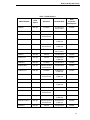


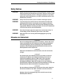


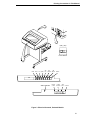
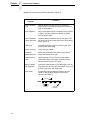


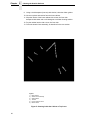
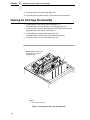


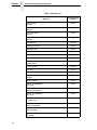
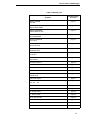

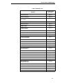

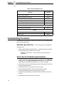


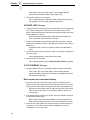
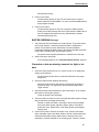
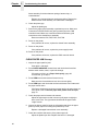
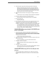
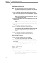

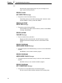

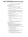
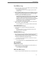
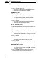
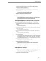
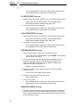

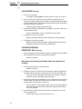
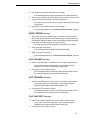


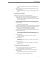
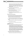


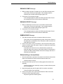
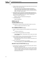


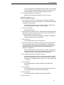
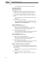
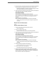


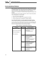

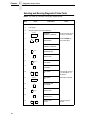

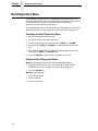
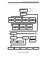


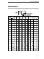

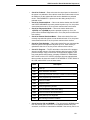


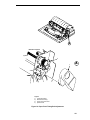
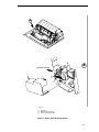
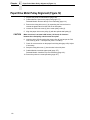
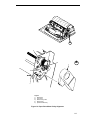

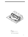

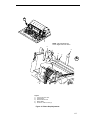


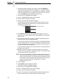


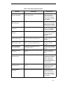

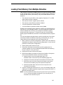


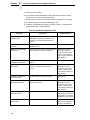
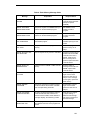
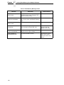


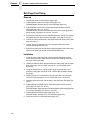


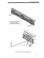


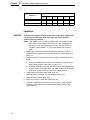
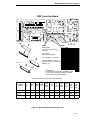

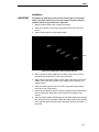

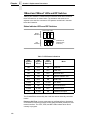
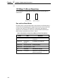


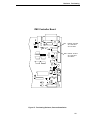


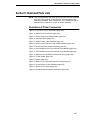
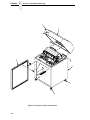
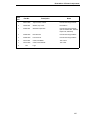
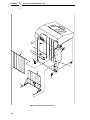
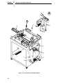


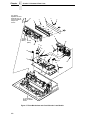

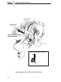

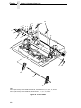

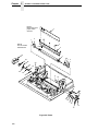


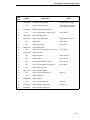


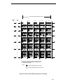


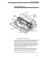
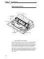
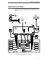
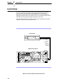
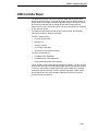
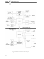
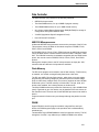


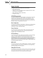


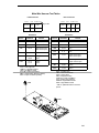
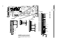
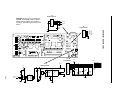


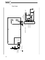
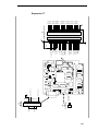
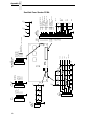
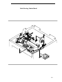

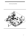
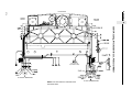
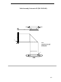
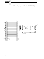
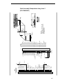
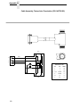
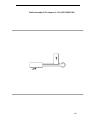
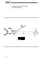

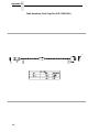


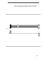
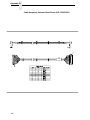
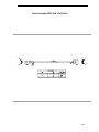
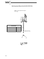

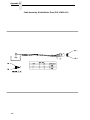
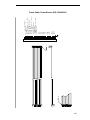
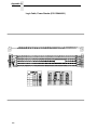
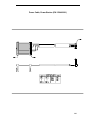

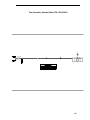
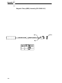
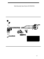


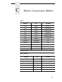
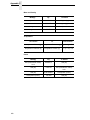
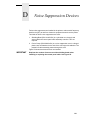
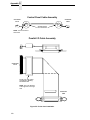
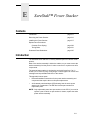

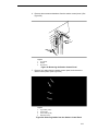
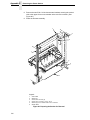
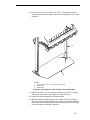
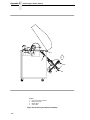
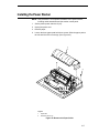
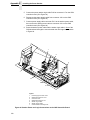

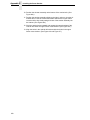


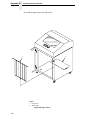
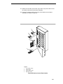
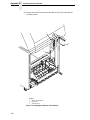

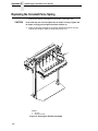


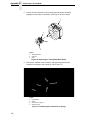

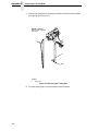

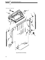


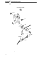
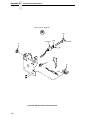
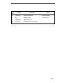
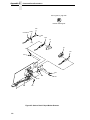


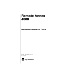

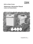


![User manual [ENG] - VegaObs Database Consultation Software](http://vs1.manualzilla.com/store/data/005911546_1-f613e0852217e54ec3af6f546af45374-150x150.png)