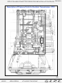
1
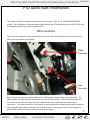
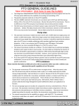
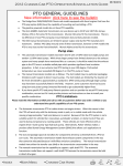
2014 Chassis Cab PTO Operation & Installation Guide
08/01/2013
PTO General Guidelines
PTO GENERAL GUIDELINES
The Ram 3500/4500/5500 Chassis cab models equipped with gas and diesel engines that have the PTO prep
option (LBN) have the capability of mounting and controlling a PTO.
The Aisin AS69RC automatic transmission can use devices up to 60HP and 250 ft lbs torque. While the model,
the number, and HP/torque capability of the transmission have increased, the Chelsea 270 and Muncie CS6
models continue to mount to the right side of the transmission as in previous years.
The G56 manual transmissions are limited in power output only by the PTO manufacturers’ maximums. Chelsea
442 (deep mount) series fit this transmission, however on 4x4 models this PTO is very close to the front
driveshaft . Muncie Alpha series fits this transmission.
For 2012 and later a left hand side PTO (option code LBV) will be available as a factory option on 4x2 chassis cab
models. This should allow for easier PTO installation on 4x2 models and allow for the shaft driven applications.
In this position, Muncie model FA6B is the only PTO that fits. However Chelsea is creating a model as well so
contact them for the latest information.
Pump sizes
The automatic transmission models have been test fit with 19 GPM rated single pumps and tandem 13GPM
rated pumps. While these larger pumps have limited clearance to the exhaust system and it has been
mentioned as a concern, it should be noted that the diesel exhaust in the PTO area is a double wall pipe which
provides significant insulation. In fact, in our testing in over 100 degree Fahrenheit ambient temperatures we
never exceeded 200 degrees F on the PTO pump or hoses. The gasoline models have larger clearance envelopes
than the diesels. However, the higher heat rejection of the gasoline engine exhaust system requires special care
to ensure the PTO pump system is protected.
The manual transmission models are as follows: The 4x2 models have no particular packaging limitations with
respect to direct mount pumps. The 4x4 models are limited by the location of the front driveshaft to
approximately a standard 11 GPM rated pump (although larger pumps may have been successfully fitted in the
field). However, some customers have had success using bent axis piston pumps (mounted forward) to get
substantially higher flows.
If you have specific PTO and pump fitment questions and can provide the actual PTO and pump combination, we
can test fit it and provide pictures and instructions on how to install your specific combination.
PTO Limitations
Please read this information carefully and call us with any questions before you order a vehicle so you understand the
specific capabilities of our PTO system.
The Automatic transmission PTO is turbine driven not engine driven. What this means is that the PTO will work
only with the stationary mode in park, or in mobile mode with the vehicle moving at approximately 7 mph and
above or in neutral. Because of this the PTO system is not a suitable system for vehicles like: snow plows,
autoloader wreckers, or dump trucks if they are used to dump and spread at a crawling speed. These vehicles
are more effective with an engine driven ‘clutch pump’ type hydraulic pump. Alternatively, Parker-Chelsea
makes a product called Stored Energy Management System (SEMS) that allows such applications to function.
The manual transmission currently has the capability to support a split shaft PTO. Approximately, mid –year the
automatic also will have this capability. The EVIC screen in the center of the instrument cluster will have a split
shaft programming function that will program the vehicle to shift to direct drive (4th gear) and hold without
upshifting. This mode will require an electrical connection to the split shaft unit confirming that the rear
driveshaft is disconnected.
1
•Index
•Main Menu
•Chassis Cab Home
+
ALL
IN
OUT
2014 Chassis Cab PTO Operation & Installation Guide
08/01/2013
Below is the new PTO programming menu contained within the Electronic Vehicle Information Center (EVIC). The EVIC is
located between the Speedometer and Tachometer. You will able to access the PTO functions by scrolling to the
commercial settings and then to PTO.
The vehicle will be factory set to stationary single mode with driver adjustable PTO speed. If this is the mode
that is needed no change in settings is required.
The factory (default) pin setting is 0000
If you require a single set speed, scroll through the PTO/Standard menu to Single Set RPM and set your speed.
If you require this speed or other settings to be ‘locked’ so that only approved people can reset the settings.
Change the 4 digit PIN code by entering the PIN setup menu. Now only people who have the PIN code can
change the settings.
Once you have the correct modes programmed, you can proceed to the quick start menu on the next page.
Settings must be made with the key in the run position but with the engine off
NOTE: You must use remote mode with an aftermarket switch when using Hard Wired Remote Start/Stop
2
•Index
•Main Menu
•Chassis Cab Home
+
ALL
IN
OUT
2014 Chassis Cab PTO Operation & Installation Guide
08/01/2013
PTO Quick Start Information
This section will give you specific instructions on how to wire a PTO on the 2013 3500/4500/5500
models. The information is tailored toward those familiar with PTO installation on the 2007 to 2012 but
can be equally helpful to anyone installing a PTO.
Wire Locations
There are two connectors under the dash which are used. They are the same connectors as previous
years, but their locations are altered.
White
Connector
Gray
Connector
Both of these connectors are located behind the VISM module towards the front of the vehicle. The
VISM module is the black plastic module next to the park brake bracket . The view above shows the
connectors on a vehicle that does not have a VISM module as it would block the view of these
connectors. The white connector is ‘tear taped’ in place and can be accessed by pulling the connector
and tearing the tape without pulling on the wires themselves. The gray connector is tie wrapped in
place so the tie wrap must be cut to access the gray connector.
3
•Index
•Main Menu
•Chassis Cab Home
+
ALL
IN
OUT
2014 Chassis Cab PTO Operation & Installation Guide
08/01/2013
The white connector contains the following circuits:
1. Z907 (Black) PTO switch return Note: V937 (Violet/brown) does not function for 2013.
2. F425 (Pink) Remote PTO switch. Connects to Z907 via the upfitter added switch. For
remote/multi-speed mode only.
The mate to this connector is the smaller black connector that comes in the upfitter kit plastic bag.
The gray connector contains the following circuits.
1.
F922 (Pink/yellow). This typically used for 12V+ ignition feed power for a PTO indicator
light if you are not using the in dash switch.
2. G425 this is the pass through wire that comes from the under hood wire you will connect to
the pressure switch.
There is a gray mating connector also in the upfitter kit plastic bag.
Note: The ground signal from the pressure switch must be connected to circuit W708
(orange/brown) located on the brown connector of the VISM. If circuit W708 does not
see a ground signal, the PTO will turn off in 30 seconds.
See the VISM section for additional instructions.
1
3
2
4
4
•Index
•Main Menu
•Chassis Cab Home
+
ALL
IN
OUT
2014 Chassis Cab PTO Operation & Installation Guide
08/01/2013
The light gray connector under the hood shown in the figure above (below the dark gray connector) next to the auxiliary
PDC contains the following connections. The Pin numbers below are molded into the surface of the connector. The
wires that plug to this connector are also in the upfitter kit plastic bag.
1.
2.
3.
4.
Not used for 2013 or later automatic transmission models
F928 (pink /yellow) Switched 12 v output that connects to the hot shift solenoid.
Z907 (Black) ground
G 425 (violet/yellow) PTO indicator light feed. This wire connects to the PTO pressure switch and feeds
through the dash to the gray under dash connector mentioned above connects to circuit W708 when the
in dash PTO switch is used.
NOTE: In all PTO modes VISM circuit W708 must see a ground signal either through the PTO pressure
switch or a direct ground circuit. If no ground is seen by engine controller, the PTO will turn off after 30
seconds.
5
•Index
•Main Menu
•Chassis Cab Home
+
ALL
IN
OUT
2014 Chassis Cab PTO Operation & Installation Guide
08/01/2013
PTO Operation
The 3500/4500/5500 Ram Chassis Cab vehicle, when equipped with either the automatic Aisin 6spd or manual G-56
6spd transmissions, will allow for an aftermarket upfit with a transmission driven PTO (power take off). The customer
will have the ability to operate the PTO in either a “stationary” or “mobile” mode. Under normal operation the vehicle
will go to a 900 rpm when PTO is engaged. By utilizing the cruise switches the idle speed can then be adjusted to
between 900 and 2000 rpm’s.
Stationary Mode
This feature interacts with the transmission to utilize an auxiliary PTO to drive equipment. Activated by a switch inside
the cab, this feature operates only when the vehicle is stationary.
Once active, the engine speed increased by holding the RES ACCEL button on the steering wheel or decreased by holding
the COAST button.
This is the factory programmed setting. If you need a single set speed, you will now be able to program it (and disable
the cruise switches) via the Electronic Vehicle Information Center (EVIC) screen in the center of the cluster.
Stationary PTO is available only when the vehicle is stationary. When the truck is equipped with an automatic
transmission, it must be in Park and the service brake must be released and functional. When the truck is equipped with
a manual transmission, the Parking Brake must be Set and the service brake must be released and functional
To operate the PTO in this mode the vehicle must meet the following conditions:
Be in “park” position ( vehicles equipped with automatic transmission)
PTO switch has been activated
Parking brake applied (vehicles equipped with manual transmission)
Clutch not depressed (clutch interlock switch)
Vehicle must be running
No transmission, engine, accelerator, brake or clutch switch faults present
PTO must be correctly installed using the vehicle provided circuits
To operate the PTO via a remote switch the customer must make sure the above conditions are met. It is vital for proper
operation that the PTO and remote have been installed correctly paying special attention to ensure the vehicle provided
wiring has been connected properly. This is the responsibility of the installer of the PTO and switches/remote system. It
is the responsibility of the PTO manufacturer to ensure that their electrical (switches and remote) system is compatible
with the vehicle’s electrical architecture and software functionality.
Mobile Mode
Mobile mode allows for use of the PTO when the vehicle is in motion. This feature, when activated by the menu
available on the Electronic Vehicle Information Center (EVIC) screen in the center of the cluster, will allow you to enter
mobile PTO mode when you press the PTO switch on the dash.
When this feature is selected stationary PTO and Remote PTO features are not available.
6
•Index
•Main Menu
•Chassis Cab Home
+
ALL
IN
OUT
2014 Chassis Cab PTO Operation & Installation Guide
08/01/2013
To operate the PTO in this mode the vehicle must meet the following conditions:
PTO switch has been activated
Vehicle must be in “park” position (vehicles equipped with automatic transmission)
Parking brake must not be applied
Clutch not depressed (clutch interlock switch)
No transmission, engine, accelerator, brake or clutch switch faults present
Vehicle must be running
PTO must be correctly installed using the vehicle provided circuits
The customer may choose to use the PTO while the vehicle is moving. To do so the PTO function must be activated prior
to taking the vehicle out of “park”. This is accomplished by activating the PTO on/off switch. At this point the customer
may place the vehicle in a forward or reverse gear and have PTO operation.
The PTO will also function in park and neutral but without an increase in idle speed. However, the accelerator pedal can
be used to increase PTO speed. Mobile mode does not provide the exact same capability as a ‘live drive’ i.e. you cannot
have PTO capability at zero vehicle speed in drive. However some customers have had success with shifting the vehicle
into neutral and allowing the vehicle to coast.
To disengage PTO operation and return to “standard vehicle operation” simply turn the up fitter provided on/off switch
to the off position.
Remote Mode Features
Remote mode allows the use of an aftermarket auxiliary switch to actuate the PTO. Presumably this will be from a
location other than the cab of the truck, or some automated/relay driven method to turn on the PTO is required.
Remote PTO can be calibrated for one to three selectable engine speeds.
Remote mode also is the only method that accommodates multiple PTO speeds. Up to three different PTO speeds can
be programmed. These speeds are programmed via the Electronic Vehicle Information Center (EVIC) screen in the
center of the cluster (see page 2). The circuits that enable these multiple speeds are contained in the Vehicle System
Interface Module (VSIM). The VSIM module is located under the dash on the driver’s side. The connecting wires are
contained in the upfitter wiring kit and VSIM wiring kit. Click here for VSIM section.
Remote PTO feature has a higher priority than Idle Up. If the Remote PTO feature is active the Idle Up switches are
ineffective. The Idle Up or Stationary PTO feature cannot be activated until the Remote PTO relinquishes control
To operate the PTO in this mode the vehicle must meet the following conditions:
Be in “park” position ( vehicles equipped with automatic transmission)
Upfitter provider (on/off) switch has been activated
Parking brake applied (vehicles equipped with manual transmission)
Clutch not depressed (clutch interlock switch)
Vehicle must be running
No transmission, engine, accelerator, brake or clutch switch faults present
PTO must be correctly installed using the vehicle provided circuits
•Index
•Main Menu
•Chassis Cab Home
7
+
ALL
IN
OUT
2014 Chassis Cab PTO Operation & Installation Guide
08/01/2013
Various features provided by the Cummins module
Remote Throttle
and Remotemust
Throttle
NOTE:
these features
be Switch
enabled by the dealer
This feature
allows
the
use of Throttle
a 0-10K or
0-100K potentiometer to function as a remote throttle. By connecting the
Remote
Throttle
and
Remote
Switch
circuits K400, F856, and K128 to the each end and the movable center leg respectively, the potentiometer will function
This
theThese
use ofcircuits
a 0-10K
0-100Kon
potentiometer
to the
function
as side
a remote
By connecting
thearea.
as a feature
remote allows
throttle.
areorlocated
a connector on
driver’s
of thethrottle.
transmission
bellhousing
circuits
K400,
andand
K128
tofunctions
the each below
end and
movable
centerare
legcontained
respectively,
theupfitters
potentiometer
function
The wiring
andF856,
for this
two
as the
wellas
schematics
in the
wiring kitwill
delivered
as
a
remote
throttle.
These
circuits
are
located
on
a
connector
on
the
driver’s
side
of
the
transmission
bellhousing
area.
with every vehicle. The dealer must enable this feature. Circuit K129 must be connected to circuit V937 to turn on this
The
wiring and for this and two functions below as wellas schematics are contained in the upfitters wiring kit delivered
feature.
with every vehicle. The dealer must enable this feature. Circuit K129 must be connected to circuit V937 to turn on this
Accelerator interlock
feature.
This allows the
accelerator to be locked out when activated. This feature is often used in conjunction with remote PTO
Accelerator
interlock
or remote throttle. While active it disables the vehicles accelerator pedal typically for safety reasons. This feature is
This
allowsbythe
accelerator
to be
locked
out whenmust
activated.
This feature
is often used in conjunction with remote PTO
activated
connecting
circuit
K 810
to V937and
be enabled
by the dealer.
or remote throttle. While active it disables the vehicles accelerator pedal typically for safety reasons. This feature is
Switched Max Operating Speed
activated
by connecting circuit K 810 to V937and must be enabled by the dealer.
This feature selects a lower maximum engine speed when the switch is on (closed to ground). The lowered engine
Switched Max Operating Speed
speed is can be changed. This feature is enabled by the dealer who also will set the maximum speed you require.
This feature selects a lower maximum engine speed when the switch is on (closed to ground). The lowered engine
Switch Return
speed is can be changed. This feature is enabled by the dealer who also will set the maximum speed you require.
Electrical return/ground for switch circuits.
Switch Return
J1939 Interface
Electrical return/ground for switch circuits.
Cummins provides this interface to “gate” certain CAN messages for customer use. It is an industry standard three way
J1939 Interface (Cummins only)
connector located underhood, on the driver’s side of the engine near the connection to the intake manifold. Messages
included are
vehiclethis
speed,
engine
brake
system
– filtered,
switch status,
clutch
switch
Cummins
provides
interface
tospeed,
“gate” park
certain
CANon/off,
messages
forvoltage
customer
use. It isbrake
an industry
standard
three
way
engaged, wait
to start
lamp status
anddriver’s
coolantside
temp.
connector
located
underhood,
on the
of the engine near the connection to the intake manifold. Messages
included are vehicle speed, engine speed, park brake on/off, system voltage – filtered, brake switch status, clutch switch
engaged, wait to start lamp status and coolant temp.
8
•Index
•Main Menu
•Chassis Cab Home
+
ALL
IN
OUT
2014 Chassis Cab PTO Operation & Installation Guide
08/01/2013
PTO Circuit Definition Chart
Location E Transmission Bellhousing Drivers Side
The following chart is provided to assist in correctly interfacing the PTO with the vehicle:
Circuit
Name Type/Gauge/Color
F856
Circuit Functionality
18T - YL/PK
K400
18T - BR/VT
K128
18T - DB/LG
K129
18T - DB
K119
18T - LG/BK
K810
18T - VT/DG
F425
V937
18T - PK
18T - VT/BR
5V engine sensor feed
Description
5 volt pwr supply to the remote potentiometer
(remote's control power circuit). Supplied by
the engine controller
Remote's ground (ground to the potentiometer
of remote). Supplied by the engine controller.
accel pedal position sensor
Do not hook to other grounding location
Remote signal sent to the engine controller.
remote throttle signal
Signal from the remote's potentiometer.
On/Off switch provided by customer to "turn
on/off remote function. Remote switch closes
remote throttle switch
to ground.
Feature selects a lower maximum engine
speed when switch is "on". Switch closes to
maximum operating speed switch
ground. Customer supplied switch.
Disable accelerator control of engine by
closing an operator installed switch. This
Accelerator interlock switch
switch closes to ground.
Customer supplied remote PTO on/off switch.
Remote PTO Switch
Switch closes to ground.
Non-Functional for 2013
Ground for 2014
Usage
Remote throttle control
Remote throttle control
Remote throttle control
Remote throttle control
Max operating speed
switch
Customer supplied
switch
Remote PTO
Signal Return
9
•Index
•Main Menu
•Chassis Cab Home
+
ALL
IN
OUT
2014 Chassis Cab PTO Operation & Installation Guide
08/01/2013
Left (Driver) Side Battery
Do not install wiring / terminals of any kind at this location
Right (Passenger) Side Battery
Do not install wiring / terminals of any kind at these locations
10
•Index
•Main Menu
•Chassis Cab Home
+
ALL
IN
OUT
2014 Chassis Cab PTO Operation & Installation Guide
08/01/2013
11
•Index
•Main Menu
•Chassis Cab Home
+
ALL
IN
OUT
2014 Chassis Cab PTO Operation & Installation Guide
08/01/2013
12
•Index
•Main Menu
•Chassis Cab Home
+
ALL
IN
OUT
2014 Chassis Cab PTO Operation & Installation Guide
08/01/2013
13
•Index
•Main Menu
•Chassis Cab Home
+
ALL
IN
OUT
2014 Chassis Cab PTO Operation & Installation Guide
08/01/2013
14
•Index
•Main Menu
•Chassis Cab Home
+
ALL
IN
OUT
2014 Chassis Cab PTO Operation & Installation Guide
08/01/2013
15
•Index
•Main Menu
•Chassis Cab Home
+
ALL
IN
OUT
2014 Chassis Cab PTO Operation & Installation Guide
08/01/2013
16
•Index
•Main Menu
•Chassis Cab Home
+
ALL
IN
OUT
2014 Chassis Cab PTO Operation & Installation Guide
08/01/2013
17
•Index
•Main Menu
•Chassis Cab Home
+
ALL
IN
OUT
2014 Chassis Cab PTO Operation & Installation Guide
08/01/2013
Aisin Automatic Transmission Remote Mode
Vehicle provided CAN
Buss communication
Transmission Controller
Engine Controller
F425(pink) – Remote Mode
PTO on/off sw.
2013 Only Z905 Black
2014 V937 VT/BR
K427
(orange/light green)
Indicator lamp
Relay Coil
F922C
(pink/yellow)
Ignition feed
14 amp max
F940
Ignition feed
F605
12V output
for PTO
VSIM Circuit W708
PTO
Solenoid
and Pump
Ground circuit
Z907 (black)
PTO indicator
pressure switch
G425 Under Hood
Notes:
Z907
Remote mode uses an upfitter installed PTO switch
Z905 and F425 are circuits that can be found located under the dash just in
board of the park brake pedal
F922C and Z907 can also be found in the same area described above
All other wiring, switches, relays and other components will need to be
provided by the PTO installer.
Do NOT externally ground circuit V937 to anything
You MUST permanently ground VSIM circuit W708
See the VSIM Circuit Definition for more information
18
•Index
•Main Menu
•Chassis Cab Home
+
ALL
IN
OUT
2014 Chassis Cab PTO Operation & Installation Guide
08/01/2013
Aisin Automatic Transmission in Cab Stationary and Mobil Mode
Vehicle provided CAN
Buss communication
Transmission Controller
Engine Controller
Factory
PTO on/off sw.
In dash
K427
(orange/light green)
Indicator lamp
Built into
PTO switch
Relay Coil
F940
Ignition feed
F928
12V output
for PTO
VSIM Circuit W708
PTO
Solenoid
and Pump
Ground circuit
Z907 (black)
PTO indicator
pressure switch
G425 Under Hood
Notes:
- Z907
K425, V937 are now connected to the in dash PTO switch, Circuit G425 that
that can be found located under the dash just in board of the park brake
pedal. Must be connected to VSIM circuit W708
F922C and Z914 can also be found in the same area described above
All other wiring, switches, relays and other components will need to be
provided by the PTO installer.
Do NOT externally ground circuit V937 to anything
You MUST connect curcuit G425 to VSIM circuit W708
See the VSIM Circuit Definition for more information
19
•Index
•Main Menu
•Chassis Cab Home
+
ALL
IN
OUT
2014 Chassis Cab PTO Operation & Installation Guide
08/01/2013
Description of Pressure Ports for the Aisin Transmission. PTO
20
•Index
•Main Menu
•Chassis Cab Home
+
ALL
IN
OUT
2014 Chassis Cab PTO Operation & Installation Guide
08/01/2013
PTO Installation Alternative
In addition to the current method of PTO installation from beneath the vehicle, an
alternative method has been developed that allows the installation from above by
removing the PTO patch panel in the floor. The instructions are as follows.
1. Remove the rear package tray located behind the seat from the vehicle.
2. Unbolt the seat and move it to the rear of the cabin where the package tray was
removed.
3. Remove the sill guards (rocker panel covers) passenger side to allow the vinyl
floor mat to be lifted. They are removed by prying straight up to disengage metal
clips.
4. Lift the floor mat and fold it rearward and toward the drivers side to expose the
patch panel
•Index
•Main Menu
•Chassis Cab Home
21
+
ALL
IN
OUT
2014 Chassis Cab PTO Operation & Installation Guide
08/01/2013
5. Remove the fasteners and sealer from around the patch panel. Cut away the sound
deadener pad to expose the transmission PTO access.
6. You are now able to install and assemble the PTO and pump through the opening.
Note: larger pumps must be inserted through the hole and moved toward the rear of
the opening before installing the PTO. The pump is then slid forward to connect to
the installed PTO.
7. To assemble, reverse the above procedure using RTV to reseal the PTO floor pan
patch panel.
•Index
•Main Menu
•Chassis Cab Home
22
+
ALL
IN
OUT