1
R i t t a l GmbH & Co. KG
®
Auf dem Stützelberg
D – 35745 Herborn
Service - Tel.: (++49) - (0)2772 / 505-1855
Service - Fax: (++49) - (0)2772 / 505-1850
Installation / Operating Instructions
SK 3318.xxx
SK 3319.xxx
SK 3320.xxx
SK 3334.xxx
SK 3335.xxx
SK 3336.xxx
SK 3338.xxx
SK 3339.xxx
SK 330x.xxx
06/2006 V01
For exact type designation see type plate
Important:
It is mandatory to read these operating instructions prior to commissioning and to keep these for
future use. The manufacturer cannot accept any liability for damage or operating problems resulting
from nonobservance of these operating instructions. The right to make technical changes for further
development is reserved.
FRIEDHELM L O H GROUP
1
ENGLISH
Recooling unit
R i t t a l GmbH & Co. KG
®
Auf dem Stützelberg
D – 35745 Herborn
1.
General description................................................................................................................. 2
2.
Important safety measures ..................................................................................................... 3
3.
Transport and handling ........................................................................................................... 4
4.
Installation............................................................................................................................... 5
5.
Electrical connection ............................................................................................................... 6
6.
Start-up ................................................................................................................................... 6
7.
Hydrological data .................................................................................................................... 7
8.
Maintenance ........................................................................................................................... 9
9.
Shutting down / disposing the cooling system...................................................................... 10
10.
General fault analysis ........................................................................................................... 11
11.
Appendix ............................................................................................................................... 13
Technical data
P+ID Schematics
Wiring plan
Description of components
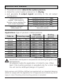
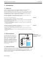
1.
General description
Intended use of the cooling system
The system is used for the cooling of water or of a water-glycol mixture.
When using other media (e.g. de-ionised water) please refer to the technical data contained in the
appendix, or contact the manufacturer. The limit values given in the technical data must in no case
be exceeded.
Warning:
The use of the system for cooling inflammable or explosive substances is prohibited:
Explosion hazard.
FRIEDHELM L O H GROUP
2
ENGLISH
Table of contents:
R i t t a l GmbH & Co. KG
®
Auf dem Stützelberg
D – 35745 Herborn
2.
Important safety measures
General notes
These operating instructions are containing basic notes which must be observed during commissioning,
operation and maintenance. It is mandatory, therefore, for the fitter and the responsible operating staff/ operator
to read these prior to commissioning. They must always be available at the location of the system. It is a must to
observe not only the general safety notes given in this section, but also the special safety notes included in the
other sections.
Qualification of personnel and training
The personnel for operation, maintenance, inspection, and installation must have the appropriate qualification
for this work. The scope of responsibility, competence, and supervision of the personnel must be defined
precisely by the operator.
Safety consciousness at work
The safety notes listed in these operating instructions, the existing national regulations for the prevention of
accidents, and also any further internal work, operating, safety regulations must be observed.
Safety notes for the operating company / operator
Any existing contact hazard protection for moving parts must not be removed from plants being in operation.
Hazards due to electrical energy must be excluded. (→ For details on this see, for instance, the VDE regulations
and those of the local utilities).
Safety notes for maintenance, inspection, and installation work
On principle, cleaning and maintenance work must be carried out only with the plant in standstill condition. It is
mandatory to follow the procedures described in the operating instructions for shut-down of the plant.
Warning! Prior to maintenance work the recooling unit must be switched voltage-free at the input end.
Immediately after completion of this work the safety and protective system must be attached again or their
function restored.
Unauthorised modification and production of spare parts
Any modification or change of the plant is allowed only as agreed with the manufacturer. Original spare parts
and accessories approved by the manufacturer enhance safety. The use of other parts can make void the
liability for the consequences arising from this.
Unallowable operating modes
The operational reliability of the system supplied is ensured only in case of intended use. The limit values given
in the technical data must in no case be exceeded.
Health hazards originating from the refrigerant
There is only very little risk to the health originating from the refrigerant. Narcotic properties are met only in case
of very high concentrations. Following direct effect of very high concentrations this is eliminated again very
quickly via the lungs. The refrigerant can have a certain irritating effect on skin and mucous membranes. The
effect of liquid refrigerant on the skin may cause frostbite. In the presence of open fire or hot surfaces
refrigerants may decompose and form poisonous decomposition products (e.g. hydrogen chloride, phosgene).
The refrigerant volatises when escaping in gaseous form into the open. An intentional discharge is not allowed.
Refrigerating systems must be positioned in a way that they do not become damaged due to internal traffic and
transport processes.
FRIEDHELM L O H GROUP
3
ENGLISH
Risks in case of nonobservance of safety notes
In case of nonobservance of the safety notes hazards may occur for personnel, as well as for the environment
and the system proper. Nonobservance of safety notes will entail loss of any rights to claim damages.
R i t t a l GmbH & Co. KG
®
Auf dem Stützelberg
D – 35745 Herborn
3.
Transport and handling
ATTENTION:
Please note when using water refrigerant!
When the recooling unit is stored or transported at temperatures below freezing point the consumer circuit must
be drained completely and if necessary flushed with a water-glycol mixture for preventing frost damage.
This also applies to the cooling circuit for water-cooled condensers.
When preventing the recooling system the weight specified on the type plate must be taken into
consideration. A fork lift truck or transport device of the appropriate carrying capacity should be used.
For preventing damage on transport:
•
The unit may be transported in upright position only.
•
Suspend the recooling unit for transport only at the lifting rings provided for this purpose or on the
pallet supplied with it.
•
Strong shocks during transport must be prevented.
FRIEDHELM L O H GROUP
4
ENGLISH
Until first start-up the cooling system may be transported only in its original packaging material. In case of
damage the manufacturer must be informed immediately. If the unit is being moved inside the works all
connections must be disconnected from the unit. Moving of the unit must be done in a manner that no damage
can occur. If damage should occur in spite of these notes, the unit must be inspected prior to renewed start-up
by an expert and be repaired if necessary.
A possibly existing tank must be emptied prior to transportation.
R i t t a l GmbH & Co. KG
®
Auf dem Stützelberg
D – 35745 Herborn
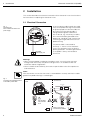
4.
Installation
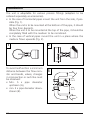
Conditions for Installation
•
The site of the recooling unit should be, if possible, directly next to the consumers for avoiding long
distances and line losses connected with this. Line losses are mainly caused by:
-
Pressure loss in line system caused by piping resistance and separate resistance due to shut-off
fittings and pipe bends.
-
Heat transfer at non-insulated pipelines due to prevailing temperature differential along the piping
•
The site for the recooling unit chosen should be such that – in case of service intervals or repair work - easy
access is possible at any time. This facilitates maintenance and repair.
•
It must be assured that the fans are not working in "air short-circuit". Air short-circuits may cause loss of
performance of the recooling unit. If ventilation of the room in which the recooling unit is placed is
insufficient room temperature may increase due to accumulated waste heat. This may cause a decrease of
performance of the cooling unit.
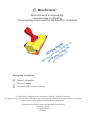
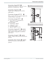
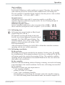
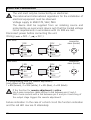
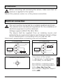
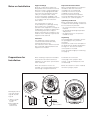
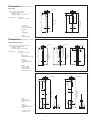
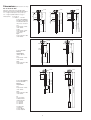
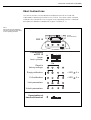
IMPORTANT:
When installing the recooling unit attention should be paid to the following:
•
With air-cooled recooling units the following minimum distances to wall and ceiling must be
maintained:
Wall:
Minimum 1 x height of condenser
Ceiling:
Minimum 3 x height of condenser
•
•
•
•
•
•
•
•
•
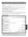
The connection of a duct for fresh and exhaust air is allowed only following prior release by the
manufacturer →loss of performance (air-cooled recooling unit).
Do not place the recooling unit in the vicinity of a heating device →loss of performance.
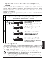
The recooling unit may be positioned only on level firm surfaces . The maximum deviation from the
vertical is 2° ensuring a safe stand.
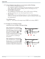
The consumer to be cooled is to be connected to the recooling unit by means of insulated piping or
hose connections.
If the consumer is positioned on a higher level than the recooling unit a non-return valve is to be
installed in the feed line and a solenoid valve in the return line →to prevent the tank from flowing
over.
With recooling units to be sited in the open under a roof the minimum outside temperature should
be taken from the technical data.
With recooling units (for water) with a tank at below-zero temperatures a water-glycol mixture of the
specified ratio, Æ see technical data, is to be filled in.
When it is possible to shut-off the consumer circuit an appropriate bypass must be provided to
protect the pump.
The circulation pump must never run dry Æ otherwise the pump will be damaged.
FRIEDHELM L O H GROUP
5
ENGLISH
system.
R i t t a l GmbH & Co. KG
®
Auf dem Stützelberg
D – 35745 Herborn
5.
Electrical connection
It is mandatory to observe the following notes:
•
The electrical connection, in accordance with the type plate, may be made only by authorised specialist
personnel.
•
Recooling units must always be integrated into the potential equalisation.
•
The conductor cross sections of the power cables must be selected according the rated current (see
nameplate).
•
The max. voltage drop must not exceed 10%.
•
With three-phase current systems the connection must be made with a clockwise rotating field.
•
The cooling system must be connected to the mains by means of a disconnecting device ensuring a
minimum contact gap of 3 mm in switched-off condition.
With a transformer installed (option) one must check whether it is connected to the correct terminal (on
primary side).
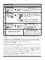
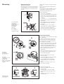
6.
•
Start-up
When connecting the recooling unit to the fluid circuit to be cooled the latter should always be
flushed. This procedure prevents any depositions existing in the fluid circuit to contaminate the
recooling unit which may, under circumstances, cause damage to or failure of the internal pump.
•
Unpack unit, place it on a level surface and align it using a spirit-level.
•
With air-cooled recooling units the siting selected must be such that no “air short-circuiting”
(hot air exit Å Æ air intake condenser) can occur.
•
Observe allowed ambient temperature and wall distance.
•
Connect to mains.
•
Make media connections.
•
Make cooling water connections (water-cooled condenser).
•
Nominal width of piping must correspond at least to the nominal width of media connections at unit.
•
Fill medium into the unit.
•
For closed systems: please prepare an admission pressure of 1.2-2 bar.
•
Start up recooling unit.
•
Check direction of rotation of motors.
•
Vent piping, top up medium.
•
Activate cooling water circuit (water-cooled condenser).
•
Check connection lines and pipe connections during start-up phase for leak-tightness.
Prolonged standstill
If a prolonged standstill of the system is intended, drain the medium circuit completely. For renewed start-up of
the system the same checks are be carried out as with initial start-up.
FRIEDHELM L O H GROUP
6
ENGLISH
•
R i t t a l GmbH & Co. KG
®
Auf dem Stützelberg
D – 35745 Herborn
7.
Hydrological data
In order to prevent problems in the water circuit (this also applies to water-cooled units) it is mandatory
to comply with the VEB Cooling water guidelines (VGB-R 455 P).
Antifreeze component in cooling water: see technical data
Note:
We have to point out again that without water treatment it is only seldom possibly to achieve
satisfactory conditions. The water treatment by the client must ensure that even with extreme
conditions depositions and corrosion are avoided.
IMPORTANT
Only fill in distilled or DI water in recooling units specified for this purpose (see data sheet).
Treatment and/ or maintenance of the water in recooling units
The cooling water must meet particular conditions, depending on the installation to be cooled. Depending on its
contamination and size and design of the recooling unit a suitable process will then be employed for water
treatment and/ or maintenance. The most frequent types of contamination and normal processes for dealing
with these in industrial cooling are:
•
Mech. contamination:
Filtering of the water using screen filters, gravel filters, cartridge filters, precoated filters
•
Hardness too high:
Softening of the water by ion exchange
•
Moderate content of mechanical contamination and hardness constituents:
Softening of the water by ion exchange
•
Moderate content of chemical contamination:
Inoculation of the water with passivators and/ or inhibitors
•
Biological contamination, slime bacteria, and algae:
Inoculation of the water with biocides
FRIEDHELM L O H GROUP
7
ENGLISH
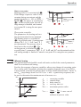
Cooling water and/ or cold water must not cause sediments of water scale or lose precipitation. It should also be
of low hardness, in particular of low carbonate hardness. Particularly with cooling by circulating operation
carbonate hardness should not be too high. On the other hand, the water should not be soft to an extent that
materials are attacked. When the cooling water is recooled the salt content should not increase due to
evaporation to an extent that with increasing concentration of dissolved substances the electric conductivity
increases, making the water more corrosive. Therefore, not only a corresponding amount of fresh water must
always be added, but also a part of the enriched water must be taken out.
R i t t a l GmbH & Co. KG
®
Auf dem Stützelberg
D – 35745 Herborn
Check water quality regularly.
Evaporation processes at the system water surface have a thickening effect on the system water.
Remove thickened water from the system by water exchange, in order to keep water values within the
required limits.
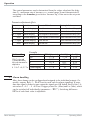
The properties of the water used should not deviate from the hydrological data listed below.
7 - 8,5
Carbonate hardness
3 - 8° dH
Free carbon dioxide
8 - 15 mg/dm3
Associated carbon dioxide
8 - 15 mg/dm3
Aggressive carbon dioxide
0 mg/dm3
Sulphides
Zero
Oxygen
< 10 mg/dm³
Chloride ions
< 50 mg/dm³
Sulphate ion
< 250 mg/dm³
Nitrates and nitrites
< 10 mg/dm³
CSB (chemical oxygen consumption)
<7 mg/dm³
Ammonia
< 5 mg/dm³
Iron
< 0.2 mg/dm³
Manganese
< 0.2 mg/dm³
Conductivity
200 – 2200 µS/cm
Residue on evaporation
< 500 mg/dm³
Potassium permanganate
consumption
< 25 mg/dm³
Suspended matter
< 3 mg/dm³
FRIEDHELM L O H GROUP
ENGLISH
pH value
3 – 15 mg/dm³
Split stream cleaning recommended
> 15 mg/dm³
Continuous cleaning recommended
8
R i t t a l GmbH & Co. KG
®
Auf dem Stützelberg
D – 35745 Herborn
8.
Maintenance
The cooling circuit which is a hermetically sealed system has been filled at works with the required volume of
refrigerant, tested for leak tightness, and subjected to a functional trial run.
Attention!
Prior to maintenance work the recooling unit must be switched voltage-free at the input end.
Simply sweeping the outside with the fan running will not afford thorough cleaning. It is absolutely necessary to
use oil-solving agents, like cleaner's naphtha, or similar, for cleaning and we recommend using a spray gun for
penetrating into the depth of the condenser. When doing this, functional components, mounted in the lower part,
must be well covered in order to remove the flushed contamination and to prevent damage to surrounding
components. Cleaning should be done at regular intervals with the frequency depending on the degree of
contamination in the room where the system is put up.
With cooling of / with water or similar media please pay attention always to:
•
Solid matter residues (clean used filters regularly, if applicable)
•
Algae and depositions
•
Corrosion
may cause irreversible damage to the recooling unit. Such residues will always have the effect that the
performance of the recooling unit can suffer. The manufacturer's guarantee and liability become void in
cases of incorrect use and treatment of the recooling unit. In such cases we do not accept any liability
for damage.
FRIEDHELM L O H GROUP
9
ENGLISH
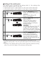
Important!
•
For ensuring proper function of the recooling unit it is a must to take care that the laminae of the
air-cooled condenser are kept clean.
• Oil-containing ambient air in combination with dust will cause increased dirt deposition on the
condenser laminae. Here, the following should be observed:
R i t t a l GmbH & Co. KG
®
Auf dem Stützelberg
D – 35745 Herborn
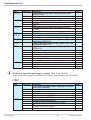
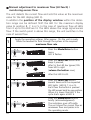
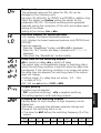
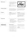
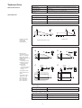
Summary of service activities recommended by us
Compressor
• No servicing is required with fully hermetic compressors.
Fan (air-cooled recooling unit)
• Check noise level
Æ ½ year
Condenser (air-cooled recooling unit)
• Clean laminae by compressed air or by sweeping
Æ 2 months
• Clean filter mat
Æ 4 weeks
Please note the special data in the appendix
Inspection glass cooling circuit (unit-specific)
• Check moisture indicator,
green for dry = OK,
yellow for moist,
possible moisture in cooling circuit or condenser defect
Æ ½ year
Consumer medium
• Check medium circuit for contamination and possible solid matter (chips or similar)
Æ 4 weeks
Tank, components, and all connections (piping, valves and fittings, hoses) of consumer circuit
• Check for leaks
Æ 1 week
Filling level medium
• Check for sufficient filling level, top up if necessary
Æ 1 week
Electrical connections
• Check terminals and connections
Æ ½ year
9.
Shutting down / disposing the cooling system
Shutting down / disposing the recooling unit may be carried out only by authorised expert personnel.
Because the refrigerant will volatise when escaping in gaseous form into the open intentional blowing off is not
permitted. The refrigerant and the components of the cooling unit must be disposed of in accordance with the
rules of the trade and local regulations. The same applies to the oil in the compressor and possibly present
waste water.
FRIEDHELM L O H GROUP
10
ENGLISH
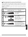
Condenser (water-cooled recooling system)
®
R i t t a l GmbH & Co. KG
Auf dem Stützelberg
D – 35745 Herborn
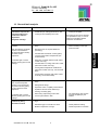
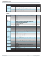
10. General fault analysis
Problem
Possible cause
Remarks
Insufficient cooling
performance resp. low air
outlet temperature from
condenser at ambient
temperature.
-
Refrigerant shortage is announced by a
marked drop of cooling performance. The
cooling circuit is leaking in this case.
-
-
A specialist is needed for
manual resetting of the highpressure limiter
-
The evaporating coils must be
covered completely by the
medium.
Refrigerant shortage
Eliminate leakage and top up
cooling circuit again.
The cooling circuit may be repaired
by a specialist firm only. In case of
cooling circuit problems please
contact the manufacturer.
-
Too high ambient temperature (see technical
data)
When the allowed condenser
pressure is exceeded the
high-pressure limiter will trip
and switch off the
compressor.
-
Nonobservance of required distances
(see siting)
-
Contaminated condenser or filter (option)
-
Too high feed medium temperature (see
technical data)
An indicator light or a fault
indicator (option) gives a fault
message.
-
Water-flow controller defective (with watercooled units only)
-
Contamination of cooling water inlet / outlet
(with water-cooled units only)
-
Cooling water temperature outside limits
(with water-cooled units only, see technical
data)
-
Cooling water shortage (with water-cooled
units only, see technical data)
-
Too low ambient temperature (see technical
data)
-
Refrigerant shortage
-
Expansion valve or capillary tube defective
-
Operation solenoid valve defective (if
existing, see wiring plan)
An indicator light or a fault
indicator (option) gives a fault
message.
-
When using evaporating coils in tank:
not enough medium in tank
Compressor is
continuously being
switched on and off
-
Cooling performance of recooling system too
high
-
Differential gap of controller too small
-
Check parameter setting
-
Medium temperature too high
-
Check temperature of medium
Evaporator pressure
If the required evaporator
pressure is not reached the
low-pressure limiter (option)
trips and switches off the
compressor.
FRIEDHELM L O H GROUP
11
ENGLISH
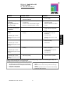
Increased condenser
pressure
®
R i t t a l GmbH & Co. KG
Problem
Possible cause
Remarks
Unit does not work
-
Check voltage supply
-
-
Contactor defective
Check function and rating of
current supply.
Compressor, pump, and fan are working
Condenser or air inlet filter heavily
contaminated
-
Cleaning without using any
aggressive agents
Cooling performance low
-
Air short-circuit: hot air is taken in again
because of obstacles at place of siting
-
Remove obstacles or re-direct
air flow
Insufficient cooling effect
and condensate formation
at condenser
-
Volume flow through evaporator too low
-
Check function of pump
-
Check heat loss of hydraulic
circuit
Compressor without
function
-
-
Condenser pressure too high
(contaminated air filter or
condenser)
-
Air short-circuit
-
Ambient temperature too high
(>45° C)
-
High pressure loss (Obstacles in
area of air outlet).
-
Fan blocked
-
Compare pressure of pump with
data on nameplate
-
Cooling insufficient (air inlet
contaminated)
-
Pump blocked
Current input high
Thermal stop of compressor (motor circuitbreaker)
An indicator light or a fault
indicator (option) gives a fault
message.
Fan without function
-
Thermal stop of fans (motor circuit-breaker)
An indicator light or a fault
indicator (option) gives a fault
message
Pump without function
-
Thermal stop of pumps (motor circuitbreaker)
An indicator light or a fault
indicator (option) gives a fault
message
No medium circulation
-
Pump blocked
-
Check pump
An indicator light or a fault
indicator (option) gives a fault
message
-
Valve shut possibly
-
Open the valve in question
While in continuous operation, the recooling system is in stable operating condition. The recooling system keeps the
medium feed temperature at the set desired value.
Possible causes for deviation from desired value could be:
-
Cooling demand too high (see technical data)
Too high ambient temperature (see technical data)
Required distances are not held (see technical data)
Evaporator contaminated
Condenser contaminated
FRIEDHELM L O H GROUP
-
12
Refrigerant shortage (bubble formation in inspection
glass)
Medium level too low in tank (not with once-through
cooler)
Medium temperature set too low (see technical data)
Parameters set incorrectly
ENGLISH
Auf dem Stützelberg
D – 35745 Herborn
R i t t a l GmbH & Co. KG
®
Auf dem Stützelberg
D – 35745 Herborn
11. Appendix
Technical data
•
P+ID Schematics
•
Wiring plan
•
Description of components
ENGLISH
•
FRIEDHELM L O H GROUP
13
R i t t a l GmbH & Co. KG
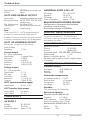
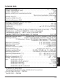
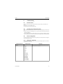
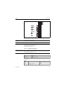
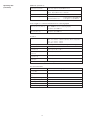
Technische Daten
Technical data
Caractéristiques techniques
Dati tecnici
Auf dem Stützelberg
D – 35745 Herborn
Service - Tel.: (++49) - (0)2772 505-1855
Service - Fax: (++49) - (0)2772 505-1850
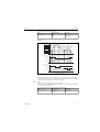
SK3335.069, WA Nr.: 6952001/001, Masch.-Nr. 06 06 19
Deutsch
Nennspannung
English
Rated voltage
Netzfrequenz
Mains frequency
Nennstrom
Rated current
Steuerspannung
Control voltage
tension de
contrôle
Anlaufstrom
Start-up current
Anschlussleistung
Kühlleistung
Connected load
Courant de
démarrage
Puissance
connectée
Puissance
frigorifique
Cooling output
Kältemittel
Refrigerant
Kältemittelmenge Refrigerant
quantity
TemperaturbeTemperature
reich Umgebung range ambient
air
Tank
Tank capacity
Français
Tension
nominale
Fréquence du
réseau
Courant nominal
Italiano
Tensione
nominale
Frequenza di
rete
Corrente
nominale
Controlli la
tensione
Corrente di
spunto
Potenza
allacciata
Potenza
frigorifera
Geräuschpegel
Noise level
Agent réfrigérant
Quantité de
réfrigérant
Zone de
température de
l'air ambiant
Capacité de
réservoir
Niveau sonore
Gewicht
Weight
Poids
Refrigerante
Quantità di
refrigerante
Gamma di temperatura dell'aria
ambiente
Volume utile
vasca
Livello di
rumorosità
Peso
Abmessungen
Breite
Höhe
Tiefe
Dimensions
Width
Height
Depth
Dimensions
Largeur
Hauteur
Profondeur
Dimensioni
Larghezza
Altezza
Profondità
Temperatur
Vorlauf
Hysterese
Nennförderleistung
Temperature
outlet
Hysteresis
Rated delivery
power
Rohranschluss,
Vorlauf
Rohranschluss,
Rücklauf
Pipe connection,
outlet
Pipe connection,
inlet
Température
vidange
Hystérésis
Puissance
nominale de
débit
Connexion de
tuyau, vidange
Connexion de
tuyau, admission
Temperatura
scarico
Isteresi
Potenza
nominale di
flusso
Connessione
tubo, scarico
Connessione
tubo, immissione
Part de l'antigel
Percentuale
antigelo
Nostra direttiva
interna:
Fornitore
Tipo
Frostschutzanteil Anti-frost agent
content
Wir empfehlen:
We recommend:
Hersteller
Typ
Manufacturer
Type
FRIEDHELM L O H GROUP
Fournisseur
préconisé:
Fabricant
Type
400 V / 3~ / PE
50 Hz
12 A
24VDC / 230 VAC
3 x INenn
4200 W
6000 W
TW1 = +18°C / TU = +32°C
R407 C
3,5kg
+10°C bis +43C
150 ltr.
70 dB(A)
280 kg
1200 mm
2000 mm
600 mm
+18°C
+2 K
21,5 ltr./min bei
0,5bar absolut
1 ¼“ IG
1 ¼“ IG
30 % max
Clariant
Antifrogen N
®
0
2
1
4
3
5
6
7
8
9
ESSE002D
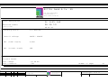
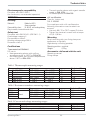
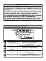
RITTAL GmbH & Co. KG
Auf dem Sttzelberg
D-35745 Herborn
http://www.rittal.de
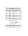
Plant designation
SK 3335.169
Maschine number
06 06 19
Drawing number
06 06 19
Incoming supply
3 x 400V/PE
Control voltage
24VDC/ 230VAC
max. power supply
4,2kW
max. current supply
12A
Project leader
:
Last change
: 22.06.06
Last processor
: TRA
Number of pages
12
2
Datum
WA 6952001/001
Rittal GmbH & Co. KG
Auf dem Sttzelberg
Bearb. TRA
Gepr.
nderung
Datum
Name
Norm
22.06.06
SK 3335.169
Urspr.
D - 35745 Herborn
Ers.f.
Ers.d.
Cover
Zeichnungsnummer: 06 06 19
=
+
1
Bl.
12
Bl.
0
2
1
4
3
5
6
7
8
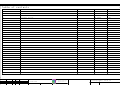
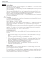
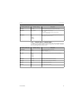
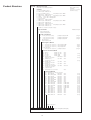
Table of contents
Page
Name of the page
1
2
9
ESSJ010D
addition of page
Date
Processor
X
Cover
22.06.06
TRA
Table of contents
22.06.06
TRA
3
Main current
22.06.06
TRA
4
Control circuit
22.06.06
TRA
5
Thermostat
22.06.06
TRA
6
Pump control
22.06.06
TRA
7
Water level control
22.06.06
TRA
8
Fault signal
22.06.06
TRA
9
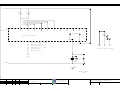
Flowdiagram
22.06.06
TRA
10
Clamp plan X1
22.06.06
TRA
X
11
Stckliste
22.06.06
TRA
X
12
Stckliste
22.06.06
TRA
X
X
1
3
Datum
WA 6952001/001
Rittal GmbH & Co. KG
Auf dem Sttzelberg
Bearb. TRA
Gepr.
nderung
Datum
Name
Norm
22.06.06
SK 3335.169
Urspr.
D - 35745 Herborn
Ers.f.
Ers.d.
Table of contents
Zeichnungsnummer: 06 06 19
=
+
2
Bl.
12
Bl.
0
2
1
5
4
3
6
7
8
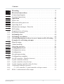
9
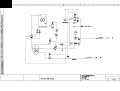
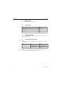
L1 /4.0
L3 /4.0
1
3
5
L1
L2
L3
Hauptschalter
N /4.0
-Q0
1
3
5
-Q1
4,5-6,3A
Set: 6A
-K1
5.7
2
4
6
1
3
5
2
4
6
13
21
14
5.7
22
8.1
1
3
5
-Q2
3,5-5A
Ieinst.: 4A
-K2
6.8
2
4
6
1
3
5
2
4
6
13
21
14
6.8
22
8.2
5,5KW
Sp1 /6.0
Sp2 /6.0
PE
PE
X1
1
2
3
N
PE
X1
PE
5
U1
L1
L2
L3
N
PE
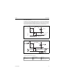
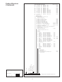
-M1
R407C
Input
6
7
V1
W1
M
3
~
PE
X1
38
39
PE
X1
8
U1
10
V1
W1
X1
PE
3
PE
~
11
U1
M
-M2
Compressor
9
13
V1
W1
M
-M3
3
PE
Fan
12
~
PE
CV/+
0V/-
PE
Pump
0...10V Signal
Pump
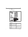
3x400V / PE /50 Hz
MTZ 28-4
S 4 D 350
MHIE 205-2G
U:400V 50Hz
U:400V 50Hz
U:400V
I:5,5A
I:0,34A
I: 4A
P:3,2KW
P:0,16KW
P:1,5KW
2
4
Datum
WA 6952001/001
Rittal GmbH & Co. KG
Auf dem Sttzelberg
Bearb. TRA
Gepr.
nderung
Datum
Name
Norm
22.06.06
SK 3335.169
Urspr.
D - 35745 Herborn
Ers.f.
Ers.d.
Main current
Zeichnungsnummer: 06 06 19
=
+
3
Bl.
12
Bl.
0
2
1
5
4
3
6
7
8
9
3.9/ L1
L02 /7.0
3.9/ L3
3.9/ N
N /7.0
-F1
-F2
-F3
-F4
500mA
500mA
2A
2A
-T1
EKL 1,0
0V
400V
-K3
6.4
24VDC
2A
0V
24V
-
+
1
3
2
4
1
-F1
2A
-
2
+
PE
X1
24VDC
-PE1
14
15
PE
/5.0
L1
-M4
0VDC /5.0
N
M
1
~
PE
X1
42
43
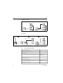
for extern signals
Vakuum pump
3
5
Datum
WA 6952001/001
Rittal GmbH & Co. KG
Auf dem Sttzelberg
Bearb. TRA
Gepr.
nderung
Datum
Name
Norm
22.06.06
SK 3335.169
Urspr.
D - 35745 Herborn
Ers.f.
Ers.d.
Control circuit
Zeichnungsnummer: 06 06 19
=
+
4
Bl.
12
Bl.
0
4.3/
2
1
5
4
3
6
7
8
24VDC
9
24VDC
/6.0
F3 /8.2
F4 /8.2
F5 /8.2
F6 /8.2
-U1
8.0
A1
11
MPRA-SMK...-F
21
.
Stufe 1
12
X1
X1
F
Stufe 3
.
.
14
F
22
20
21
.
Stufe 2
.
A2
31
.
1
.
.
24
32
-B1
.
34
KTY10-6
2
16
-P1
P78B
-K2
A
+
ND
6.8
-
-Y1
40
P
-
HD
14
38
B
X1
13
X1
18
-Q1
+
3.3
13
14
P
D
C
X1
19
PE
PE
PE
PE
X1
X1
17
A1
41
-K1
-V1
A2
4.3/
0VDC
0VDC /6.0
Thermostat
Pressostat
Probe
1
2 3.3
3
4 3.3
5
6 3.3
Compressor
4
6
Datum
WA 6952001/001
Rittal GmbH & Co. KG
Auf dem Sttzelberg
Bearb. TRA
Gepr.
nderung
Datum
Name
Norm
22.06.06
SK 3335.169
Urspr.
D - 35745 Herborn
Ers.f.
Ers.d.
Thermostat
Zeichnungsnummer: 06 06 19
=
+
5
Bl.
12
Bl.
0
5.9/
2
1
5
4
3
6
7
8
9
24VDC
24VDC
X1
-S2
22
X1
HI-Teach
-K10T
-S1
KS41-1
.5
PN 7009
( Oeffner )
26
23
-U2
F2 /8.2
ELEKTRONISCHER
STROEMUNGSWAECHTER
IFM
TYP: SI10xx
X1
/7.0
0 1 2 3 4 5 6 7 8 9
15
-K11T
LO-Teach
16
.6
0 1 2 3 4 5 6 7 8 9
18
1
15
16
18
Schaltpunkt
0 1 2 3 4 5 6 7 8 9
2
3
2
0 1 2 3 4 5 6 7 8 9
4
Verz /7.8
3
(OUT3)
(OUT3)
(INP2)
(INP2)
(di1)
(INP1)
(INP1)
(INP1)
X1
27
X1
28
X1
29
4
7/8
9/+
1
P
6
schwarz
(OUT3)
OUT
5
(OUT2)
L+
4
3
2
-K5
braun
(OUT1)
L-
(N)
Fernabgleich
1
blau
(L)
7.4
21
22
10
11
X1
12
30
31
32
13
14
15
X1
24
-Q2
25
3.7
-B2
1
13
14
3
4-20mA
0-30bar
A1
3.8/ Sp2
-K3
A1
-V3
-K10T
A1
B1
A1
-K11T
A2
A2
-K2
-V2
A2
A2
3.8/ Sp1
5.9/
0VDC
0VDC /7.0
Funktion: R/ 3s
Remote
1
2 4.7
3
4 4.8
15
18 .6
1
16 .5
3
Pressure control
Pressure control
Float switch
-B2
S1
-S2
Regulator for pump M3
Vakuum pump
2 3.6
4 3.7
5
6 3.7
13
14 5.7
Pump
5
7
Datum
WA 6952001/001
Rittal GmbH & Co. KG
Auf dem Sttzelberg
Bearb. TRA
Gepr.
nderung
Datum
Name
Norm
22.06.06
SK 3335.169
Urspr.
D - 35745 Herborn
Ers.f.
Ers.d.
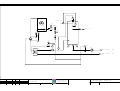
Pump control
Zeichnungsnummer: 06 06 19
=
+
6
Bl.
12
Bl.
0
6.9/
2
1
5
4
3
6
7
8
9
24VDC
24VDC /8.0
6.5/
Verz
4.9/ L02
-K12T
.3
15
16
-K7
18
.7
11
14
-K7
.7
21
24
-U3
RIA 452
81
L
41
51
.
.
Relais 1
42
52
Relais 4
.
.
53
82
.
Relais 3
.
.
43
54
.
Relais 2
.
N
44
45
.
.
46
55
.
11
56
12
PE
1
X1
33
34
S1
2
-B3
-
+
PE
A1
-H1
-H2
weiá
gelb
-K12T
A1
-H3
A2
A1
-K5
-K7
A2
rot
H5
A2
4.9/ N
6.9/
0VDC
0VDC /8.0
Function: WU 1s
Water level
18 .7
15
indicator
21
22 6.8
Water level sensor
16 .7
11
14 .7
21
24 .8
Water level "full"
Water level
Warning horn
Warning horn
> 40%
"dry run"
RESET
dry run
Water level
< 0%
"water level indicator"
< 10%
6
8
Datum
WA 6952001/001
Rittal GmbH & Co. KG
Auf dem Sttzelberg
Bearb. TRA
Gepr.
nderung
Datum
Name
Norm
22.06.06
SK 3335.169
Urspr.
D - 35745 Herborn
Ers.f.
Ers.d.
Water level control
Zeichnungsnummer: 06 06 19
=
+
7
Bl.
12
Bl.
0
7.9/
2
1
5
4
3
6
7
8
9
24VDC
21
-Q1
3.4
22
21
-Q2
3.7
22
5.9/ F6
5.9/ F5
5.9/ F4
5.9/ F3
6.9/ F2
-U1
5.2
MPRA-SMK...-F
F1
F2
F3
F4
F5
F6
F7
F8
F9
F10
-K6
.5
Fault signal modul
11
12
14
41
42
F1:
Motor circuit switch
F2:
Float control
F3:
Temperature low
F4:
Temperature to high
F5:
Low pressure
F6:
High pressure
44
X1
35
36
37
Fault signal contact
F7:F8:F9:F10:_
A1
-K6
-H6
A2
7.9/
0VDC
14 .8
11
12 .8
Fault signal
lamp
7
9
Datum
WA 6952001/001
Rittal GmbH & Co. KG
Auf dem Sttzelberg
Bearb. TRA
Gepr.
nderung
Datum
Name
Norm
22.06.06
SK 3335.169
Urspr.
D - 35745 Herborn
Ers.f.
Ers.d.
Fault signal
Zeichnungsnummer: 06 06 19
=
+
8
Bl.
12
Bl.
0
2
1
5
4
3
6
7
8
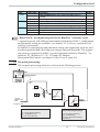
9
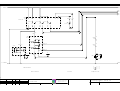
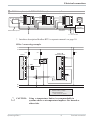
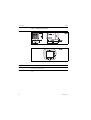
LIS
1.1
R 1 1/2"
Vakuum pump
R 1"
Vakuum
2.1
PIS
R 1/2"
Vakuum meter
-M2
3.1
Fill 1" IG
R 1"
Y1
-P1
HD
ND
4.1
-M1
5.1
IN
R 1 1/4"
R 1 1/4"
Saugstutzen
FC
TC
1.1
-U1
-M3
PIS
In 1 1/4"
IG
21,5l/min.
-B1
Out 1 1/4"
IG
8
10
Datum
WA 6952001/001
Rittal GmbH & Co. KG
Auf dem Sttzelberg
Bearb. TRA
Gepr.
nderung
Datum
Name
Norm
22.06.06
SK 3335.169
Urspr.
D - 35745 Herborn
Ers.f.
Ers.d.
Flowdiagram
Zeichnungsnummer: 06 06 19
=
+
9
Bl.
12
Bl.
0
2
1
5
4
3
6
7
8
Clamp plan
9
ESSK016D
Name of terminal blockX1
Cable name
wire
cable
Target-
type
name
Cl.Connect
Nb.
Target
Brigde
name
Connect
Cable name
wire
Cable
Side/
type
Path
Function text
L1
1
L1 -Q0
L1
3.0 Input
L2
2
L2 -Q0
L2
3.0 =
L3
3
L3 -Q0
L3
3.1 =
N
N
N -K3
3
3.1 =
PE
3.1 =
-M1
U1
5
-K1
2
3.3 Compressor
-M1
V1
6
-K1
4
3.3 =
-M1
W1
7
-K1
6
3.3 =
PE
3.3 =
-M2
U1
8
-K1
2
3.4 Fan
-M2
V1
9
-K1
4
3.4 =
-M2
W1
10
-K1
6
3.4 =
11
-K2
2
3.6 Pump
12
-K2
4
3.7 =
13
-K2
6
3.7 =
PE
3.5 =
PE
3.7 =
-M4
L1
14
-K3
2
4.7 Vakuum pump
-M4
N
15
-K3
4
4.8 =
PE
4.8 =
-P1
A
16
-U1
14
-K2
13
17
-P1
C
5.2 =
-U1
F5
18
-P1
B
5.3 =
-U1
F6
19
-P1
D
5.3 =
5.2 Pressostat
WX1/-B1
1
-B1
1
20
-U1
F
5.5 Probe
WX1/-B1
2
-B1
2
21
-U1
F
5.5 =
22
-U1
31
6.1 Remote
-U2
1
23
-B2
1
24
-B2
3
25
-U2
13
6.2 =
-S1
1
26
-K10T
A1
6.3 Pressure control S1
-U2
2
27
-S1
3
6.3 =
-K3
A1
28
-S1
2
6.4 =
29
-S1
4
6.4 =
-S2
1
-K11T
B1
30
-K11T
A2
31
6.1 =
6.2 Pressure control -B2
6.6 Float switch -S2
6.6 =
32
6.7 =
-B3
-
33
-U3
11
7.6 Water level sensor
-B3
+
34
-U3
81
7.6 =
35
-K6
11
8.7 Fault signal contact
36
-K6
12
8.8 =
37
-K6
14
8.8 =
38
-U2
7/-
3.8 0...10V Signal Pump
39
-U2
9/+
3.8 =
40
-U1
14
42
-T1
+
4.2 for extern signals
43
-T1
-
4.2 =
5.1
41
5.1
9
11
Datum
22.06.06
WA 6952001/001
Rittal GmbH & Co. KG
Auf dem Sttzelberg
Bearb. TRA
Gepr.
nderung
Datum
Name
Norm
22.06.06
SK 3335.169
Urspr.
D - 35745 Herborn
Ers.f.
Ers.d.
Clamp plan X1
Zeichnungsnummer: 06 06 19
=
+
10
Bl.
12
Bl.
0
2
1
5
4
3
6
7
8
9
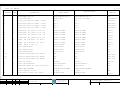
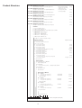
List of parts
COMPONENT
AMOUNT
NIL_133E / 02.04.03
DESIGNATION
IDENTIFICATION
ORDER NUMBER
SUPPLIER
PAGE
PATH
-B2
1
DRUCKTRANSMITTER 1/4"
DRUCKTRANSMITTER 1/4"
DRUCKTRANSMITTER 1/4"
Wilo
-B3
1
Messwertaufnehmer
942205-9000
MULTICAP T DC11TEN
Endress&Hauser 7.5
-F1
1
Feinsicherungshalter 5x20mm, 2,5qmm
ASK 1
ASK 1
Weidmueller
4.2
-F2
1
Feinsicherungshalter 5x20mm, 2,5qmm
ASK 1
ASK 1
Weidmueller
4.2
-F3
1
Feinsicherungshalter 5x20mm, 2,5qmm
ASK 1
ASK 1
Weidmueller
4.5
-F4
1
Feinsicherungshalter 5x20mm, 2,5qmm
ASK 1
ASK 1
Weidmueller
4.5
-H1
1
Leuchtmelder mit glatter Linse (ws)
3SB32 44-6AA60
3SB32 44-6AA60
Siemens
7.2
-H2
1
Leuchtmelder mit glatter Linse (ge)
3SB32 44-6AA30
3SB32 44-6AA30
Siemens
7.2
-H3
1
Leuchtmelder mit glatter Linse (rt)
3SB32 44-6AA20
3SB32 44-6AA20
Siemens
7.4
-H6
1
Leuchtmelder mit glatter Linse (rt)
3SB32 44-6AA20
3SB32 44-6AA20
Siemens
8.6
-K1
1
SCHšTZ, 230 V,50/60 Hz, 5,5 KW,1S,
3RT10 17-1AP01
3RT1017-1AP01
Siemens
5.7
-K2
1
SCHšTZ, 230 V,50/60 Hz, 5,5 KW,1S,
3RT10 17-1AP01
3RT1017-1AP01
Siemens
6.8
-K3
1
SCHšTZ
3RT1017-1BB41
3RT1017-1BB41
Siemens
6.4
-K5
1
Relais RSS214-24VDC
RSS214-24VDC
RSS214-24VDC
Tele
7.4
-K6
1
Relais RSS214-24VDC
RSS214-24VDC
RSS214-24VDC
Tele
8.5
-K7
1
Relais RSS214-24VDC
RSS214-24VDC
RSS214-24VDC
Tele
7.7
-K10T
1
Zeitrelais MRF 24VAC/DC-110-240VAC
MRF
MRF
Conta-Clip
6.5
-K11T
1
Zeitrelais MRF 24VAC/DC-110-240VAC
MRF
MRF
Conta-Clip
6.6
-K12T
1
Zeitrelais MRF 24VAC/DC-110-240VAC
MRF
MRF
Conta-Clip
7.3
-M1
1
Kompressor MTZ28-4
MTZ28-4
MTZ28-4
Maneurop
3.3
-M2
1
Lfter S4D-350-AP08-01
S4D-350-AP08-01
S4D-350-AP08-01
EBM
3.4
-M3
1
Pumpe MHIE 205/2G mit Frequenzumrichter
MHIE 205/2G
MHIE 205/2G
Wilo
3.6
-M4
1
VAKUUM-PUMPE N026ANE
VAKUUM-PUMPE N026ANE
VAKUUM-PUMPE N026ANE
KNF
4.7
-P1
1
Duo-Druckw„chter P 78 B
P 78 B
P 78 B
PENN
5.2
-Q0
1
Hauptschalter 9,5kW, 25A, Schwarz
3LD2103-0TK51
3LD2103-0TK51
Siemens
3.0
24VDC, 5,5kW, 1S
6.1
10
12
Datum
21.06.06
WA 6952001/001
Rittal GmbH & Co. KG
Auf dem Sttzelberg
Bearb. TRA
Gepr.
nderung
Datum
Name
Norm
22.06.06
SK 3335.169
Urspr.
D - 35745 Herborn
Ers.f.
Ers.d.
Stckliste
Zeichnungsnummer: 06 06 19
=
+
11
Bl.
12
Bl.
0
2
1
5
4
3
6
7
8
9
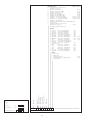
List of parts
COMPONENT
NIL_133E / 02.04.03
AMOUNT
DESIGNATION
IDENTIFICATION
ORDER NUMBER
SUPPLIER
PAGE
PATH
-Q1
1
Motorschutzschalter 3RV 1011-1GA10 /4,5-6,3
3RV 1011-1GA10 /4,5-6,3
3RV 1011-1GA10 /4,5-6,3
Siemens
3.3
-Q2
1
Motorschutzschalter 3RV 1011-1FA10 /3,5-5
3RV 1011-1FA10 /3,5-5
3RV 1011-1FA10 /3,5-5
Siemens
3.6
-S1
1
Drucksensor PN7009
PN7009
PN7009
ifm electronic 6.3
S1
1
™ffnerelement 3SB34 00 -0C
3SB34 00 -0C
3SB34 00 -0C
Siemens
7.7
S1
1
3SB30 00-0AA71
3SB30 00-0AA71
TASTER 3SB30 00-0AA71
Siemens
7.7
-S2
1
Stroemungswaechter SI 1000
SI 1000 STROEMUNGSWAECH.
SI 1000 STROEMUNGSWAECH.
ifm electronic 6.6
-T1
1
Netzteil EKL 1,0
EKL 1,0
EKL 1,0
MARX
4.1
-U1
1
Temperaturregler MPRA-SMK-A-3-KT-F / 24UCV
MPRA-SMK-A-3-KT-F
MPRA-SMK-A-3-KT-F
ers
5.2
-U2
1
Temp. regler KS 41
KS41-113-000D-000
KS41-113-000D-000
PMA
6.0
-U3
1
PROZESSANZEIGER
51008029
PROZESSANZEIGER RIA452
Endress&Hauser 7.1
-V1
1
RC Beschaltung 24VAC/DC, S00
3 RT 1916-1CB00
3 RT 1916-1CB00
Siemens
5.7
-V2
1
RC Beschaltung 127...240VAC, S00
3 RT 1916-1CD00
3 RT 1916-1CD00
Siemens
6.9
-V3
1
RC Beschaltung 24VAC/DC, S00
3 RT 1916-1CB00
3 RT 1916-1CB00
Siemens
6.4
-Y1
1
Magnetventilspule 24VDC
SPULE 24VDC
SPULE 24VDC
CASTEL
5.1
-Y1
1
RC-GLIED 24VUC
RC-GLIED 24VUC
RC-GLIED
Murrelektronik 5.1
11
Datum
21.06.06
WA 6952001/001
Rittal GmbH & Co. KG
Auf dem Sttzelberg
Bearb. TRA
Gepr.
nderung
Datum
Name
Norm
22.06.06
SK 3335.169
Urspr.
D - 35745 Herborn
Ers.f.
Ers.d.
Stckliste
Zeichnungsnummer: 06 06 19
=
+
12
Bl.
12
Bl.
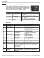
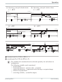
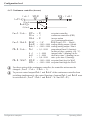
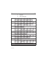
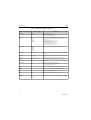
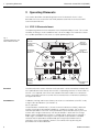
MPR-SMK-A-x-xx-x ENG
Parameter-List for temperature controller MPR-SMK-A-x-xx-x
Working level
Indication
Present value
Target value
Description
The present temperature of the medium as measured is permanently displayed.
Press the SET button to see the target temperature set for output port relay K1.
Press the “RESET” button to reset a failure message
C – Parameter level
Switching to C-Parameter level:
Press the “UP” and “Down” arrow key simultaneously for 5 seconds
until “C1”
appears on the display.
Back to working level : Press “UP” and “DOWN” arrow key for 5 seconds.
Indication
Zone
Description
C1
C2
C3
C4
Target temperature C1
Target temperature C2
Target temperature C3
Target temperature C4
Compressor
Temperature high
Temperature low
(depends on setting in parameter P5)
C20
C21
C22
C23
Hysteresis for target-temperature C1
Hysteresis for target-temperature C2 (if present)
Hysteresis for target-temperature C3 (if present)
Hysteresis for target-temperature C4 (depends on setting in parameter P5)
C91
Actual value correction for sensor (offset value)
C99
Button lock
1,5K
1K
1K
0K
0 = not locked
1 = locked
Seite 1 von 1
+18°C
+30°C
+5°C
-
0
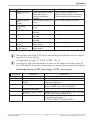
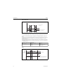
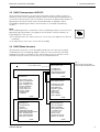
MPR-SMK-A-x-xx-x ENG
P – Parameter level
Switching to P-Parameter level: Jump first into C-Parameter level than press the “UP” arrow key
simultaneously till “C99” appears. Hold down the “UP” arrow key and press
additionally the “Down” arrow key till “P1” is seen on the display.
Back to working level: Press “UP” and “DOWN” arrow key for 5 seconds.
Parameter
Description
Zone
P1
Switching direction Relay K1
P2
Switching direction Relay K2 (if present)
P3
Switching direction Relay K3 (if present)
P4
Switching direction Relay K4
(depends on setting in parameter P5)
P5
General function for relay K4
P6
Wire protection function for all fault inputs
P7
Alarmfunction relay K4
(only active if P5 = 1 or 2)
P10
P11
P12
Function K1 in event of sensor failure
Function K2 in event of sensor failure
(if present)
Function K3 in event of sensor failure
(if present)
P13
Function K4 in event of sensor failure
P15
Hysteresis mode target temperature C1
P16
P17
P18
P20
P21
P22
P23
P24
P25
P26
P27
Hysteresis mode target temperature C2 (if
present)
Hysteresis mode target temperature C3 (if
present)
Hysteresis mode target temperature C4
(depends on settingin parameter P5)
Limit for target temperature C1 downwards
Limit for target temperature C1 upwards
Limit for target temperature C2 downwards
(if present)
Limit for target temperature C2 upwards
(if present)
Limit for target temperature C3 downwards
(if present)
Limit for target temperature C3 upwards
(if present)
Limit for target temperature C4 downwards
Limit for target temperature C4 upwards
0 = Heating contact
1 = Cooling contract
0 = Heating contact
1 = Cooling contract
0 = Heating contact
1 = Cooling contract
0 = Heating contact
1 = Cooling contract
0 = control contact
1 = alarm contact
2 = alarm contact for upper- or – lower
target value C4
0 = Fault recognition by “low” input signal
1 = Fault recognition by “high” input signal
0 = Relay K4 is off at alarm or fault signal
1 = Relay K4 is on at alarm or fault singal
0 = inactive in event of failure
1 = active in event of failure
0 = inactive in event of failure
1 = active in event of failure
0 = inactive in event of failure
1 = active in event of failure
0 = inactive in event of failure
1 = active in event of failure
0 = symmetrical
1 = only on one side
0 = symmetrical
1 = only on one side
0 = symmetrical
1 = only on one side
0 = symmetrical
1 = only on one side
1
0
1
-
1
1
0
0
0
0
0
1
1
1
1
-50°C .. +150°C
-50°C .. +150°C
+10°C
+25°C
-50°C .. +150°C
+30°C
-50°C .. +150°C
+40°C
-50°C .. +150°C
+0°C
-50°C .. +150°C
+5°C
-50°C .. +150°C
-50°C .. +150°C
Seite 2 von 2
MPR-SMK-A-x-xx-x ENG
Parameter
Description
Zone
P30
P31
P32
P33
P34
P35
P36
P37
Limit for hysteresis 1 downwards (parameter C20)
Limit for hysteresis 1 upwards (parameter C20)
Limit for hysteresis 2 downwards (parameter C21)
Limit for hysteresis 2 upwards (parameter C21)
Limit for hysteresis 3 downwards (parameter C22)
Limit for hysteresis 3 upwards (parameter C22)
Limit for hysteresis 4 downwards (parameter C23)
Limit for hysteresis 4 upwards (parameter C23)
0,1K .. 99,9 K
0,1K .. 99,9 K
0,1K .. 99,9 K
0,1K .. 99,9 K
0,1K .. 99,9 K
0,1K .. 99,9 K
0,1K .. 99,9 K
0,1K .. 99,9 K
P50
P51
P52
P53
P54
P55
Minimum action time for relay K1
Minimum pause time for relay K1
Minimum action time for relay K2 (if present)
Minimum pause time for relay K2 (if present)
Minimum action time for relay K3 (if present)
Minimum pause time for relay K3 (if present)
Minimum action time for relay K4 (depends on setting
0...999 Sec.
0...999 Sec.
0...999 Sec.
0...999 Sec.
0...999 Sec.
0...999 Sec.
0 sec.
0 sec.
0 sec.
0 sec.
0 sec.
0 sec.
0...999 Sec.
0 sec.
0...999 Sec.
0 sec.
P56
in parameter P5)
P57
Minimum pause time for relay K4 (depends on setting
P99
Temperature unit °C / °F
in parameter P5)
0 = °C
1 = °F
Fault And Error Codes
The display shows the relevant fault code in case of a fault. (display flashes)
Code
Description
F1
F2
F3
F4
F5
F6
F7
F8
F9
F10
Failure on input 1
Failure on input 2
Failure on input 3
Failure on input 4
Failure on input 5
Failure on input 6
Failure on input 7
Failure on input 8
Failure on input 9
Failure on input 10
E1
E2
FFF
F13
Short circuit sensor
Damaged sensor
Motor circuit breaker
Float control
Temperature low
Temperature high
Low pressure
High pressure
-
Exceeded maximum measurement field of sensors
Memory error
Seite 3 von 3
1K
3K
1K
3K
1K
3K
-
0
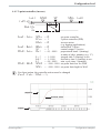
MPR-SMK-A-x-xx-x ENG
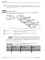
Error detection
at “low” signal
Error detection
at“high” signal
Device
Device
Device
Device
Device
Device
Device
Device
Device
Device
10
9
8
7
6
5
4
3
2
1
KS
A2
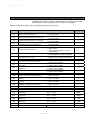
10 9 8 7 6 5 4 3 2 1 Faultinputs
A1
16 17 18 19 20 21 22 23 24 25 26 27 28 29 30
1 2 3 4 5 6 7 8 9 10 11 12 13 14 15
A1 = Positive operating Voltage / phase L1
A2 = Neutal wire (N)
K1..K3 = Relay contacts
KS
= Relay contact depents on configuration
- Control contact
- Fault contact
- Fault contact and temperature alarm
contact.
Sensor
K1
K2
K3
A1 A2
Supply
Connecting diagram (the right number of replays are shown of the device label)
Seite 4 von 4
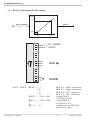
MPR-SMK-A-x-xx-x ENG
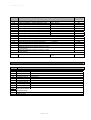
Specification of the temperature controller MPR-SMK-x-xx-x
Connecting Diagram
Technical Data
Number of Sensors:
Type of Sensor:
Effective range :
1
KTY 81-210 (PT100)
-50°C bis +150°C
The effective range is only good if you use a right type of sensor
and wiring.
Output
Number of outputs:
Output 1 … 4 (K1 .. KS):
Max. 3 + 1
Two way contact (voltage free)
Max. switching current 10A (1,5)A
Max. switching voltage 250V~
Number of inputs:
10
Note: Connect the inputs always with A1!!
Features
- Two-step regulator
- Free adjustable Hysteresis
- Heating/cooling interchangeable
- Temperature alarm
- Fault indicator with 10 digital inputs
44 41 42 NC
10 9
8
7
6
5
4
3
K4:= 230V
10A AC1
2
Operation voltage
1
24V AC with ( 50 ... 60 ) Hz or 230V AC ( 50 … 60 ) Hz
(Use only the operation voltage as shown on the device label)
Connectors
K1..K3:= 230V 10AC1
- Screw terminals and plug connectors
- 2 x 15 polar, grid 5,00 mm for 2,5 mm² wire
Sample – please refer the label of your device
Display
- 3 digits LED-Display red, 13,0 mm
- 4 LEDs for output status control
- Range of display from –99 to 999
Housing
The regulator is fit for board montage
Front-panel
Front-panel cut-out
Installation depth
( 48 x 96 ) mm
( 42 x 90 ) mm
ca. 88 mm
Protection code IP64 (Front panel side)
Ambient temperature
Operating temperature:
Storage temperature:
Max. humidity:
Seite 5 von 5
0°C … +50°C
-20°C … +70°C
75 % (no condensation)
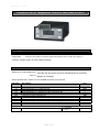
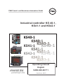
PMA Prozeß- und Maschinen-Automation GmbH
Industrial controller KS 40-1,
KS41-1 and KS42-1
KS40-1
KS41-1
KS40-1
KS42-1
KS41-1
KS42-1
Operating manual
English
9499-040-62711
Valid from: 8415
û BlueControl®
More efficiency in engineering,
more overview in operating:
The projecting environment for the BluePort controllers
on
!
s
ON ate
I pd de
T
N U e.
E and nlin D
T
ATrsion ma-o A-C
e .p PM
V
ni ww r on
i
M w o
Description of symbols:
g General information
a General warning
l Attention: ESD sensitive devices
© PMA Prozeß- und Maschinen-Automation GmbH Printed in Germany
All rights reserved. No part of this document may bereproduced or published in any form or by any means
without prior written permission from the copyright owner.
A publication of PMA Prozeß- und Maschinen Automation
P.O.Box 310229
D-34058 Kassel
Germany
Contents
1
2
2.1
2.2
3
3.1
3.2
3.3
3.4
3.5
3.5.1
3.5.2
3.5.3
3.5.4
3.5.5
3.5.6
3.6
3.7
3.8
4
4.1
4.2
4.3
4.4
4.4.1
4.4.2
4.4.3
4.4.4
4.4.5
4.4.6
4.4.7
Mounting . . . . . . . . . . . . . . . . . . . . . . . . . . . . . . 5
Electrical connections . . . . . . . . . . . . . . . . . . . . . . . 6
Connecting diagram . . . . . . . . . . . . . . . . . . . . . . . . . 6
Terminal connection. . . . . . . . . . . . . . . . . . . . . . . . . 6
Operation . . . . . . . . . . . . . . . . . . . . . . . . . . . . . 10
Front view . . . . . . . . . . . . . . . . . . . . . . . . . . . . . 10
Behaviour after power-on . . . . . . . . . . . . . . . . . . . . . 11
Operating level . . . . . . . . . . . . . . . . . . . . . . . . . . . 11
Maintenance manager / Error list . . . . . . . . . . . . . . . . 12
Self-tuning . . . . . . . . . . . . . . . . . . . . . . . . . . . . . 14
Preparation for self-tuning . . . . . . . . . . . . . . . . . . . . . .
Self-tuning sequence . . . . . . . . . . . . . . . . . . . . . . . . .
Self-tuning start
. . . . . . . . . . . . . . . . . . . . . . . . .
Self-tuning cancellation . . . . . . . . . . . . . . . . . . . . . . .
Acknowledgement procedures in case of unsuccessful self-tuning
Examples for self-tuning attempts . . . . . . . . . . . . . . . . .
.
.
.
.
.
.
14
14
15
15
16
16
Manual tuning . . . . .
Alarm handling. . . . .
Operating structure . . .
Configuration level . .
Configuration survey
Configuration . . . . .
Set-point processing . .
Configuration examples
.
.
.
.
.
.
.
.
.
.
.
.
.
.
.
.
.
.
.
.
.
.
.
.
.
.
.
.
.
.
.
.
.
.
.
.
.
.
.
.
.
.
.
.
.
.
.
.
.
.
.
.
.
.
.
.
.
.
.
.
.
.
.
.
.
.
.
.
.
.
.
.
.
.
.
.
.
.
.
.
.
.
.
.
.
.
.
.
.
.
.
.
.
.
.
.
.
.
.
.
.
.
.
.
.
.
.
.
.
.
.
.
.
.
.
.
.
.
.
.
.
.
.
.
.
.
.
.
On-Off controller / Signaller (inverse) . . . . . . . . . . .
2-point controller (inverse) . . . . . . . . . . . . . . . . .
3-point controller (relay & relay) . . . . . . . . . . . . . .
3-point stepping controller (relay & relay) . . . . . . . . .
Continuous controller (inverse) . . . . . . . . . . . . . . .
- Y - Off controller / 2-point controller with pre-contact
KS4x-1 with measured value output . . . . . . . . . . . .
Operating KS4x-1
3
.
.
.
.
.
.
.
.
.
.
.
.
.
.
.
.
.
.
.
.
.
.
.
.
.
.
.
.
.
.
.
.
.
.
.
.
.
.
.
.
.
.
.
.
.
.
.
.
.
.
.
.
.
.
.
.
.
.
.
.
.
.
.
.
.
.
.
.
.
17
18
20
21
21
22
29
30
.
.
.
.
.
.
.
.
.
.
.
.
.
.
.
.
.
.
.
.
.
30
31
32
33
34
35
36
5
5.1
5.2
5.3
5.4
5.5
5.5.1
5.5.2
6
7
8
8.1
Parameter setting level .
Parameter survey . . . . .
. . . . . . . . . . . . . .
. . . . . . . . . . . . . .
Parameters . . . . . . . .
Input scaling . . . . . . .
.
.
.
.
.
.
.
.
.
.
.
.
.
.
.
.
.
.
.
.
.
.
.
.
.
.
.
.
.
.
.
.
.
.
.
.
.
.
.
.
.
.
.
.
.
.
.
.
.
.
.
.
.
.
.
.
.
.
.
.
.
.
.
.
.
.
.
.
.
.
.
.
.
.
.
.
.
.
.
.
.
.
.
.
.
.
.
.
.
.
.
.
.
.
.
.
.
.
.
.
.
.
.
.
.
.
.
.
.
.
.
.
.
.
.
.
.
.
.
.
.
.
.
.
.
.
37
37
37
37
38
40
Input Inp.1 . . . . . . . . . . . . . . . . . . . . . . . . . . . . . . . 40
Input InP.2
. . . . . . . . . . . . . . . . . . . . . . . . . . . . 40
Calibration level .
Programmer
. .
Timer . . . . . . .
Setting up the timer
.
.
.
.
.
.
.
.
.
.
.
.
8.1.1
8.1.2
8.1.3
8.1.4
Operating modes .
Tolerance band . .
Timer start . . . . .
Signal end . . . . .
.
.
.
.
.
.
.
.
.
.
.
.
8.2
8.3
9
10
11
12
12.1
Determining the timer run-time
Starting the timer
. . . . . .
BlueControl . . . . . . . . . .
Versions . . . . . . . . . . . .
Technical data . . . . . . . .
Safety hints . . . . . . . . . .
Resetting to factory setting. . .
.
.
.
.
.
.
.
.
.
.
.
.
.
.
.
.
.
.
.
.
.
.
.
.
.
.
.
.
.
.
.
.
.
.
.
.
.
.
.
.
.
.
.
.
.
.
.
.
.
.
.
.
.
.
.
.
.
.
.
.
.
.
.
.
.
.
.
.
.
.
.
.
.
.
.
.
.
.
.
.
.
.
.
.
.
.
.
.
.
.
.
.
.
.
.
.
.
.
.
.
.
.
.
.
.
.
.
.
.
.
.
.
.
.
.
.
.
.
.
.
.
.
.
.
.
.
.
.
.
.
.
.
.
.
.
.
.
.
.
.
.
.
.
.
.
.
.
.
.
.
.
.
.
.
.
.
.
.
.
.
.
.
.
.
.
.
.
.
.
.
.
.
.
.
.
.
.
.
.
.
.
.
.
.
.
.
.
.
.
.
.
.
.
.
.
.
.
4
.
.
.
.
.
.
.
.
.
.
.
.
.
.
.
.
.
.
.
.
.
.
.
.
.
.
.
.
.
.
.
.
.
.
.
.
.
.
.
.
.
.
.
.
.
.
.
.
.
.
.
.
.
.
.
.
.
.
.
.
.
.
.
.
.
.
.
.
.
.
.
.
.
.
.
.
41
44
46
46
.
.
.
.
.
.
.
.
.
.
.
.
46
47
47
48
.
.
.
.
.
.
.
.
.
.
.
.
.
.
.
.
.
.
.
.
.
48
48
49
50
51
55
56
Operating KS4x-1
Mounting
1 Mounting
min.48 (1.89")
96 (3.78")
SP.X
126
125
60°C
min.
0°C
48 (1.89")
+0, 8
(
max.
92
8
11
5
6
4.
(3.62" +0. 03)
(
")
(0 1.
.0 .1
4. 0
.0
.4
")
10
")
4
0.
Front view KS41-1
max.
95% rel.
SP.x
126.
125
Err
KS 41-1 universal
96 (3.78")
%
45 +0,6
run
Ada
(1.77" +0.02)
Err
Front view KS42-1
126.
96 (3.78")
SP.x
KS 40-1 universal
48 (1.89")
run
Ada
10V i mA/Pt
Loc
mA/Pt
Loc Loc
10V 10V
mA/Pt
Loc 10V mA/Pt
Safety switch
run
Ada
Err
125
KS 42-1 universal
96 (3.78")
Ü
or:
Ü
*
*
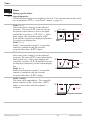
Safety switch:
For access to the safety switches, the controller must be withdrawn from the housing. Squeeze the top and bottom of the front bezel between thumb and forefinger
and pull the controller firmly from the housing..
10V i mA/Pt
Loc
right
left
open
closed
1
Factory setting
1
1
Current signal / Pt100 / thermocouple at InP.1
Voltage signal at InP.1
Access to the levels is as adjusted by means of BlueControl
(engineering tool) 2
all levels accessible wihout restriction
2
Default setting: display of all levels
suppressed, password PASS = OFF
Safety switch 10V i mA/Pt always in position left or right. Leaving the
a safety
switch open may lead to faulty functions!
l
Caution! The unit contains ESD-sensitive components.
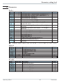
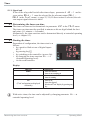
Operating KS4x-1
5
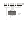
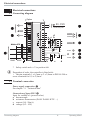
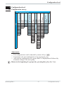
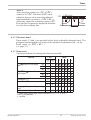
Electrical connections
2 Electrical connections
2.1 Connecting diagram
Option
1
di2
2
3
di3
UT
5
RXD-B
RGND
GND
RXD-A
DATA B
DATA A
RS485
*
g
TXD-B
TXD-A
4
6
5
7
9
Modbus RTU
3
4
8
6
a
7
10
8
11
9
12
13
14
15
(16)
17
RS422
90...250V
24V AC/DC
L
N
1
(2)
OUT1
OUT2
d
e c b
Logic
OUT3
U
10
HC mA
11
12
INP2
di1
13
mA
14
0..10 V*
INP1
15
a
b c
d
Safety switch mA i V in position left
Dependent of order, the controller is fitted with :
w flat-pin terminals 1 x 6,3mm or 2 x 2,8mm to DIN 46 244 or
screw terminals for 0,5 to 2,5mm²
2.2 Terminal connection
Power supply connection 1
See chapter 11 "Technical data"
Connection of input INP1 2
Input for variable x1 (process value)
a thermocouple
b resistance thermometer (Pt100/ Pt1000/ KTY/ ...)
c current (0/4...20mA)
d voltage (0/2...10V)
Connecting diagram
6
Operating KS4x-1
Electrical connections
Connection of input INP2 3
Heating current input (0...50mA AC) or input for ext. set-point (0/4...20mA)
3 INP2 current tansformer
L
1
Connection of input di1 4
Digital input, configurable as switch or
push-button
Connection of outputs OUT1/2 5
Relay outputs 250V/2A normally open with
common contact connection
2
3
4
5
6
Logic
SSR
_
7
8
+
9
10
11
Connection of output OUT3 6
a relay (250V/2A), potential-free
changeover contact
universal output
b current (0/4...20mA)
c voltage (0/2...10V)
d transmitter supply
e logic (0..20mA / 0..12V)
12
13
14
15
N
5 OUT1/2 heating/cooling
L
1
2
3
Connection of inputs di2/3 7 (option)
Digital inputs (24VDC external), galvanically isolated, configurable as switch or
push-button
4
5
6
7
8
9
Connection of output UT 8 (option)
Supply voltage connection for external energization
10
11
12
13
14
15
Connection of bus interface 9 (option)
RS422/485 interface with Modbus RTU
protocol
Operating KS4x-1
+
N
7
Terminal connection
Electrical connections
7 8 di2/3, UT 2-wire transmitter supply
6 OUT3 transmitter supply
Option
5mA
+24VDC
-
1
1
(2)
0V
17,5V
22mA
+
2
3
5mA
+
5
-
7
4
6
5
9
7
10
8
11
9
12
15
2
13
(16)
-
14
17
J
+
-
11
14
K
OUT3
10
13
3
13V
22mA
6
8
12
1
+
3
4
15
+
-
2
3
1
x
K
If U and the universal output OUT3 is used there may be no external galvanic
a connection
between measuring and output circuits!
T
6 OUT3 as logic output with solid-state relay (series and parallel connection)
Series connection
Parallel connection
3
4
5
Imax=22mA
4V
6
Logic
7
8
Terminal connection
+
SSR
_
12V
4V
9
10
SSR
_
+
SSR
_
4V
7
8
Imax=22mA
12V
9
SSR
_
+
SSR
_
+
+
8
Operating KS4x-1
Electrical connections
9 RS485 interface (with RS232-RS485 interface converter) *
12
RGND
RT = 120...200 Ohm
RT
11
14
DATA B
12
15
DATA B
13
(16)
DATA A
RGND
10
13
DATA A
14
17
15
12
13
14
15
(16)
17
10
RGND
11
12
DATA B
13
14
DATA A
15
12
10
13
11
14
PC
12
15
13
(16)
14
17
15
R=100 Ohm
max. 1000m
”Twisted Pair”
RGND connection optional
J
*
converter
RS485-RS232
RT
RT = 120...200 Ohm
Interface description Modbus RTU in seperate manual: see page 50.
KS4x-1 connecting example:
L1
L2
fuse
fuse
KS 40-1
1
1
2
2
contactor
3
3
4
4
5
5
6
Logic
fuse
TB 40-1 1
Temperature limiter
7
8
9
6
SSR
_
7
8
+
9
10
10
11
11
12
12
13
13
14
14
15
15
+
heating
reset
+
N1
N2
1 TB 40-1 Temperature limiter
Standard version (3 relays):
TB40-100-0000D-000
r other versions on request
a CAUTION:
Operating KS4x-1
Using a temperature limiter is recommendable in
systems where overtemperature implies a fire hazard or
other risks.
9
Terminal connection
Operation
3 Operation
3.1 Front view
1
KS40-1
1
9
0
!
SP.x
2
3
OK
126.
125
run
Ada
Err
2
3
5
6
7
8
4
$
"
%
§
KS 40-1 universal
KS41-1
SP.x
126.
125
run
KS42-1
SP.x
Ada
Err
run
Ada
Err
126.
125
KS 41-1 universal
KS 42-1 universal
1 Status of switching outputs
OuT.1... 3
2 Lit with limit value 1 ( PArA /
Lim ) not exceeded
3 Process value display
4 Set-point, controller output
5 Signals ConF and PArA level
6 Programmer or timer running
7 Self-tuning active
8 Entry in error list
9 Set-point SP.2 or SP.E is
effective
0 Set-point gradient effective
! Manual/automatic switch-over:
Off:
Automatic
On:
Manual
(changing possible)
Blinks: Manual
(changing not possible
(r ConF/ Cntr/ MAn)
" Enter key:
calls up extended operating
level / error list
§ Up/down keys:
changing the set-point or the
controller output value
$ Manual mode /spec. function
( ConF / LOGI )
% PC connection for
BlueControl (engineering
tool)
LED colours:
LED 1, 2, 3:
LED OK:
other LEDs:
g
Front view
yellow
green
red
In the upper display line, the process value is always displayed. At parameter,
configuration, calibration as well as extended operating level, the bottom display
line changes cyclically between parameter name and parameter value.
10
Operating KS4x-1
Operation
3.2 Behaviour after power-on
After supply voltage switch-on, the unit starts with the operating level.
The unit is in the condition which was active before power-off.
If KS4x-1 was in manual mode before power-off, the controller starts with correcting value Y2 after switching on again.
3.3 Operating level
The content of the extended operating level is determined by means of BlueControl (engineering tool). Parameters which are used frequently or the display of
which is important can be copied to the extended operating level.
Automatic
126
time
out
125
È
Ì
Manual
126
iÒ i
Ù
y 21
È
Ì
Ù
Ò
126
126
y 21
Ù
time
out
125
È
Ì
only
display
Ù
Extended operating level
time
out
Errorliste (if error exists)
126
FbF.1
Operating KS4x-1
display
switching
126
2
Err
11
Err
Behaviour after power-on
Operation
3.4 Maintenance manager / Error list
With one or several errors, the extended operating level
always starts with the error list. Signalling an actual entry
in the error list (alarm, error) is done by the Err LED in
the display. To reach the error list press Ù twice.
Err LED status
blinks
(Status 2)
lit
(Status 1)
off
(Status 0)
SP.x
126
125
run
Ada
Err
Signification
Alarm due to existing
error
Proceed as follows
- Determine the error type in the error list via the
error number
- -Change to status 1 after error removal.
Error removed,
- Acknowledge the alarm in the error list pressing
Alarm not acknowledged key È or Ì
- The alarm entry was deleted (Status 0) .
No error,
-Not visible except when acknowledging
all alarm entries deleted
Error list:
Name
Description
E.1 Internal error,
E.2
Cause
- E.g. defective EEPROM
cannot be removed
Internal error, can be - e.g. EMC trouble
reset
-
E.4
Hardware error
FbF.1 Sensor break INP1
Sht.1
POL.1
FbF.2
Sht.2
POL.2
HCA
SSr
- Codenumber and hardware
are not identical
Short circuit INP1 INP1polarity error Sensor break INP2 Short circuit INP2 INP2 polarity
Heating current alarm (HCA)
Sensor defective
Faulty cabling
Sensor defective
Faulty cabling
Faulty cabling
Sensor defective
Faulty cabling
Sensor defective
Faulty cabling
Faulty cabling
Heating current circuit
interrupted, I< HC.A or I>
HC.A (dependent of
configuration)
- Heater band defective
Heating current short - Current flow in heating
circuit (SSR)
circuit with controller off
- SSR defective
Maintenance manager / Error list
-
Possible remedial action
Contact PMA service
Return unit to our factory
Keep measurement and power supply
cables in separate runs
Ensure that interference suppression of
contactors is provided
Contact PMA service
Elektronic-/Optioncard must be
exchanged
Replace INP1 sensor
Check INP1 connection
Replace INP1 sensor
Check INP1 connection
Reverse INP1 polarity
Replace INP2 sensor
Check INP2 connection
Replace sensor INP2
Check INP2 connection
Reverse INP2 polarity
Check heating current circuit
If necessary, replace heater band
- Check heating current circuit
- If necessary, replace solid-state relay
12
Operating KS4x-1
Operation
Name
Description
LooP Control loop alarm
(LOOP)
AdA.H Self-tuning heating
alarm
(ADAH)
AdA.C Self-tuning heating
alarm cooling
(ADAC)
LiM.1 stored limit alarm 1
Lim.2 stored limit alarm 2
Lim.3 stored limit alarm 3
Inf.1 time limit value
message
Inf.2 duty cycle message
(digital ouputs)
g
g
Cause
- Input signal defective or not
connected correctly
- Output not connected
correctly
- See Self-tuning heating error
status
Possible remedial action
- Check heating or cooling circuit
- Check sensor and replace it, if necessary
- Check controller and switching device
- see Self-tuning heating error status
- See Self-tuning cooling error - see Self-tuning cooling error status
status
- adjusted limit value 1
exceeded
- adjusted limit value 2
exceeded
- adjusted limit value 3
exceeded
- adjusted number of operating hours reached
- adjusted number of duty
cycles reached
check process
check process
check process
application-specific
application-specific
Saved alarms (Err-LED is lit) can be acknowledged and deleted with the digital
input di1/2/3 or the Ò-key.
Configuration, see page 27: ConF / LOGI / Err.r
If an alarm is still valid that means the cause of the alarm is not removed so far
(Err-LED blinks), then other saved alarms can not be acknowledged and deleted.
Self-tuning heating ( ADA.H) and cooling ( ADA.C) error status:
Error status
0
3
4
5
6
7
8
Operating KS4x-1
Description
No error
Faulty control action
No response of process
variable
Low reversal point
Danger of exceeded set-point
(parameter determined)
Output step change too small
(dy > 5%)
Set-point reserve too small
Behaviour
Re-configure controller (inverse i direct)
The control loop is perhaps not closed: check sensor,
connections and process
Increase ( ADA.H) max. output limiting Y.Hi or
decrease ( ADA.C) min. output limiting Y.Lo
If necessary, increase (inverse) or reduce (direct) set-point
Increase ( ADA.H) max. output limiting Y.Hi or reduce
( ADA.C) min. output limiting Y.Lo
Increase set-point (invers), reduce set-point (direct)
or increase set-point range
(r PArA / SEtp / SP.LO and SP.Hi )
13
Maintenance manager / Error list
Operation
3.5 Self-tuning
For determination of optimum process parameters, self-tuning is possible.
After starting by the operator, the controller makes an adaptation attempt, whereby the process characteristics are used to calculate the parameters for fast line-out
to the set-point without overshoot.
The following parameters are optimized when self-tuning:
Parameter set 1:
Pb1
- Proportional band 1 (heating) in engineering units [e.g. °C]
ti1
- Integral time 1 (heating) in [s] r only, unless set to OFF
td1
- Derivative time 1 (heating) in [s] r only, unless set to OFF
t1
- Minimum cycle time 1 (heating) in [s] r only, unless Adt0 was set to
“no self-tuning” during configuration by means of BlueControl®.
Pb2
ti2
td2
t2
- Proportional band 2 (cooling) in engineering units [e.g. °C]
- Integral time 2 (cooling) in [s] r only, unless set to OFF
- Derivative time 2 (cooling) in [s] r only, unless set to OFF
- Minimum cycle time 2 (cooling) in [s] r only, unless Adt0 was set to
“no self-tuning” during configuration by means of BlueControl®
3.5.1 Preparation for self-tuning
w Adjust the controller measuring range as control range limits. Set values
rnG.L and rnG.H to the limits of subsequent control. (Configuration
rControllerrlower and upper control range limits)
ConFrCntrr rnG.L and rnG.H
w Determine which parameter set shall be optimized (see tables above).
3.5.2 Self-tuning sequence
The controller outputs 0% correcting variable or Y.Lo and waits, until the process
is at rest (see start-conditions on page 8).
Subsequently, a correcting variable step change to 100% is output.
The controller attempts to calculate the optimum control parameters from the
process response. If this is done successfully, the optimized parameters are taken
over and used for line-out to the set-point.
With a 3-point controller, this is followed by “cooling”.
After completing the 1st step as described, a correcting variable of -100% (100%
cooling energy) is output from the set-point.
After successfull determination of the “cooling parameters”, line-out to the
set-point is using the optimized parameters.
Self-tuning
14
Operating KS4x-1
Operation
Start condition:
w Rest condition
For process evaluation, a stable condition is required. Therefore, the controller
waits until the process has reached a stable condition after self-tuning start.
The rest condition is considered being reached, when the process value oscillation is smaller than 0,5% of (rnG.H - rnG.L).
Set-point reserve
After having come to rest with 0% correcting variable or with Y.Lo, the
controller requires a sufficient set-point reserve for its self-tuning attempt, in
order to avoid overshoot.
Sufficient set-point reserve:
inverse controller:(with process value<set-point-(10% of SP.Hi - SP.LO)
direct controller:(with process value>set-point+ (10% of SP.Hi - SP.LO)
3.5.3 Self-tuning start
g
126
Self-tuning start can be locked via BlueControl
(engineering tool) ( P.Loc).
The operator can start self-tuning at any time.
run
SP.x
For this, keys Ù and È must be pressed simulAda
taneously. The AdA LED starts blinking. The
Err
controller outputs 0% or Y.Lo, waits until the
process is at rest and starts self-tuning (AdA
LED lit permanently).
After successful self-tuning, the AdA-LED is off and the controller continues
operating with the new control parameters.
125
3.5.4 Self-tuning cancellation
By the operator:
Self-tuning can always be cancelled by the operator. For this, press Ù and È
key simultaneously. With manual-automatic switch-over configured via Ò key,
self-tuning can also be canceled by actuating Ò key. The controller continues
operating with the old parameters in automatic mode in the first case and in manual mode in the second case.
By the controller:
If the Err LED starts blinking whilst self-tuning is running, successful self-tuning
is prevented due to the control conditions. In this case, self-tuning was cancelled
by the controller.
Dependent of control type, the output status is:
w 3-pnt. stepping controller:
actuator is closed (0% output)
w 2-pnt./ 3-pnt./ continuous controller:
If self-tuning was started from the automatic mode, the controller output is
0%. With self-tuning started from manual mode, the controller output is Y2.
Operating KS4x-1
15
Self-tuning
Operation
3.5.5 Acknowledgement procedures in case of unsuccessful self-tuning
1. Press keys Ù and È simultaneously:
The controller continues controlling using the old parameters in automatic
mode. The Err LED continues blinking, until the self-tuning error was
acknowledged in the error list.
2. Press key Ò (if configured):
The controller goes to manual mode. The Err LED continues blinking,
until the self-tuning error was acknowleged in the error list.
3. Press key Ù :
Display of error list at extended operating level. After acknowledgement
of the error message, the controller continues control in automatic mode using
the old parameters.
Cancellation causes:
r page 13: "Error status self-tuning heating ( ADA.H) and cooling ( ADA.C)"
3.5.6 Examples for self-tuning attempts
(controller inverse, heating or heating/cooling)
Start: heating power switched on
Heating power Y is switched off (1).
When the change of process value X
was constant during one minute (2),
the power is switched on (3).
At the reversal point, the self-tuning
attempt is finished and the new parameter are used for controlling to
set-point W.
Start: heating power switched off
The controller waits 1,5 minutes (1).
Heating power Y is switched on (2).
At the reversal point, the self-tuning
attempt is finished and control to the
set-point is using the new parameters.
X
W
2
t
100%
Y
0%
Start r
1
3
t reversal point
blinks
X
W
100%
Y
0%
start r
t
1
2
t reversal point
blinks
Self-tuning
16
Operating KS4x-1
Operation
Start: at set-point
Heating power Y is switched off (1).
If the change of process value X was
constant during one minute and the
control deviation is > 10% of SP.Hi SP.LO (2), the power is switched on
(3). At the reversal point, the self-tuning attempt is finished, and control
to set-point W is using the new parameters.
X
W
2
100%
Y
0%
start r
t
1
3
t reversal point
blinks
X
Three-point controller
W
The parameters for heating and cooling are determined in two attempts.
t reversal point 1
The heating power is switched on
t
(1). At reversal point 1, heating para- +100%
Y 0%
-100%
meters Pb1, ti1, td1 and t1
1
start r
2
3 t reversal point 2
are determined. The process value is
lined out to the set-point (2). The
cooling power is switched on (3). At
reversal point 2, parameters Pb2, ti2, td2 and t2 are determined and the
self-tuning attempt is finished. Control to set-point W is using the new parameters.
3.6 Manual tuning
The optimization aid should be used with units on which the control parameters
shall be set without self-tuning.
For this, the response of process variable x after a step change of correcting variable y can be used. Frequently, plotting the complete response curve (0 to 100%)
is not possible, because the process must be kept within defined limits. Values Tg
and xmax (step change from 0 to 100 %) or t and x (partial step response) can
be used to determine the maximum rate of increase vmax.
100%
y
Yh
0%
t
x
Tg
Xmax
{X
Operating KS4x-1
=
=
=
=
=
Vmax =
{t
Tu
y
Yh
Tu
Tg
Xmax
t
correcting variable
control range
delay time (s)
recovery time (s)
maximum process value
Xmax { x
= max. rate of
=
{t
Tg
increase of process value
17
Manual tuning
Operation
The control parameters can be determined from the values calculated for delay
time Tu , maximum rate of increase vmax, control range Xh and characteristic K
according to the formulas given below. Increase Xp, if line-out to the set-point
oscillates.
Parameter adjustment effects
Parameter
Control
Pb1 higher increased damping
lower
reduced damping
td1 higher reduced damping
lower
increased damping
ti1 higher increased damping
lower
reduced damping
K = Vmax * Tu
Formulas
Line-out of disturbances
Start-up behaviour
slower line-out
slower reduction of duty cycle
faster line-out
faster reduction of duty cycle
faster response to disturbances faster reduction of duty cycle
slower response to disturbances slower reduction of duty cycle
slower line-out
slower reduction of duty cycle
faster line-out
faster reduction of duty cycle
controller behavior
PID
With 2-point and
PD
3-point controllers,
the cycle time must be PI
P
adjusted to
t1 / t2 £ 0,25 * Tu 3-point-stepping
Pb1 [phy. units]
1,7 * K
0,5 * K
2,6 * K
K
1,7 * K
td1 [s]
2 * Tu
Tu
OFF
OFF
Tu
ti1 [s]
2 * Tu
OFF
6 * Tu
OFF
2 * Tu
3.7 Alarm handling
Max. three alarms can be configured and assigned to the individual outputs. Generally, outputs OuT.1... OuT.3 can be used each for alarm signalling. If more
than one signal is linked to one output the signals are OR linked. Each of the 3 limit values Lim.1 … Lim.3 has 2 trigger points H.x (Max) and L.x (Min), which
can be switched off individually (parameter = “OFF”). Switching difference
HYS.x of each limit value is adjustable.
Alarm handling
18
Operating KS4x-1
Operation
Ü Operaing principle absolut alarm
L.1 = OFF
InL.1
* Operating principle relative alarm
L.1 = OFF
InH.1
SP
InL.1
InH.1
H.1
H.1
HYS.1
HYS.1
1
LED
LED
2
1
H.1 = OFF
2
H.1 = OFF
InL.1
InH.1
SP
InL.1
InH.1
L.1
L.1
HYS.1
LED
2
HYS.1
1
2
InL.1
InH.1
LED
1
SP
InL.1
InH.1
H.1
L.1
L.1
HYS.1
H.1
HYS.1
HYS.1
2
LED
1
2
HYS.1
LED
2
LED
1
2
LED
1: normally closed ( ConF/ Out.x / O.Act=1 )
2: normally open ( ConF/ Out.x / O.Act= 0 )
g
The variable to be monitored can be selected seperately for each alarm via
configuration
The following variables can be monitored:
w process value
w control deviation xw (process value - set-point)
w control deviation xw + suppression after start-up or set-point change
w effective set-point Weff
w correcting variable y (controller output)
Operating KS4x-1
19
Alarm handling
Operation
g
If measured value monitoring + alarm status storage is chosen ( ConF / Lim /
Fnc.x = 2), the alarm relay remains switched on until the alarm is resetted in the
error list ( Lim 1..3 = 1).
3.8 Operating structure
After supply voltage switch-on, the controller starts with the operating levels.
The controller status is as before power off.
126
Ù
125
3 sec.
126
PArA
Ì
Ù
126
ConF
Ì
PASS
Ù
126
CAL
Ì
g
PArA - level:
g
ConF - level:
PASS
Ù
PASS
126
Ù
End
At PArA - level, the right decimal point of the upper
display line is lit continuously.
At ConF - level, the right decimal point of the upper
display line blinks
.
When safety switch Loc is open, only the levels enabled by mePASS ans of BlueControl (engineering tool) are visible and accessible
by entry of the password adjusted by means of BlueControl (engineering tool). Individual parameters accessible without password must be copied to the extended operating level.
Factory setting:
Safety switch
Loc
closed
open
open
open
Operating structure
Safety switch Loc closed: all levels accessible without
restriction, password PASS = OFF.
Password entered with
BluePort®
OFF / password
OFF / password
OFF
Password
Function disabled or enabled
with BluePort®
disabled / enabled
disabled
enabled
enabled
20
Access via the instrument
front panel:
enabled
disabled
enabled
enabled after password
entry
Operating KS4x-1
Configuration level
4 Configuration level
4.1 Configuration survey
C.Fnc Corr
mAn
C.Act
FAIL
rnG.L
rnG.H
Fnc.2 Y.2
Src.2 Lim.1
Fnc.3 Lim.2
Src.3 Lim.3
HC.AL LP.AL
LP.AL HC.AL
HC.SC
time
P.End
FAi.1
FAi.2
See output 1
O.tYP
O.Act
Y.1
Y.2
Lim.1
Lim.2
Lim.3
LP.AL
HC.AL
HC.SC
time
P.End
FAi.1
FAi.2
OuT.0
Out.1
O.Src
End
Othr
Display, operation,
interface
È SP.Fn StYP I.Fnc Fnc.1 O.Act
Ì b.ti S.Lin StYP Src.1 Y.1
LOGI
Digital inputs
OUt.1
Output 1
OUt.2
Output 2
OUt.3
Output 3
Lim
Limit value functions
InP.2
Input 2
InP.1
Input 1
Cntr
Control and self-tuning
ConF Configuration level
L_r bAud
SP.2 Addr
SP.E PrtY
Y.2
dELY
mAn Unit
C.oFF dP
m.Loc C.dEl
Err.r
P.run
di.Fn
Adjustment:
g
w The configuratiuons can be adjusted by means of keys ÈÌ .
w Transition to the next configuration is by pressing key Ù .
w After the last configuration of a group, donE is displayed and followed by
automatic change to the next group
Return to the beginning of a group is by pressing the Ù key for 3 sec.
Operating KS4x-1
21
Configuration survey
Configuration level
4.2 Configuration
Cntr
Name
SP.Fn
b.ti
C.Fnc
mAn
C.Act
FAIL
rnG.L
rnG.H
Adt0
Value range Description
Default
0
Basic configuration of setpoint processing
0
set-point controller can be switched over to external set-point
( LOGI/SP.E)
1
program controller
2
timer, mode 1(bandwidth-controlled, switched off at the end)
3
timer, mode 2 (bandwidth-controlled, set-point remains
active at the end)
4
timer, mode 3 (switched off at the end)
5
timer, mode 4 (set-point remains active at the end)
6
timer, mode 5 (switch-on delay)
7
timer, mode 6 (set-point switch-over)
0...9999
5
Timer tolerance band for timer mode 1, 2 and 6. The timer
starts when process value = setpoint b.ti
1
Control behaviour (algorithm)
0
on/off controller or signaller with one output
1
PID controller (2-point and continuous)
2
/ Y / Off, or 2-point controller with partial/full load
switch-over
3
2 x PID (3-point and continuous)
4
3-point stepping controller
0
Manual operation permitted
0
no
1
yes (see also LOGI/ mAn)
0
Method of controller operation
0
inverse, e.g. heating
1
direct, e.g. cooling
1
Behaviour at sensor break
0
controller outputs switched off
1
y = Y2
2
y = mean output. The maximum permissible output can be
adjusted with parameter Ym.H. To prevent determination of
inadmissible values, mean value formation is only if the
control deviation is lower than parameter L.Ym.
-1999...9999 X0 (low limit range of control) 1
0
-1999...9999 X100 (high limit range of control) 1
900
0
Optimization of T1, T2 (only visible with BlueControl!)
0
Automatic optimization
1
No optimization
1 rnG.L and rnG.H are indicating the range of control on which e.g. the
self-tuning is refering
Configuration
22
Operating KS4x-1
Configuration level
InP.1
Name
Value range Description
Default
1
Sensor type selection
0
thermocouple type L (-100...900°C) , Fe-CuNi DIN
1
thermocouple type J (-100...1200°C) , Fe-CuNi
2
thermocouple type K (-100...1350°C), NiCr-Ni
thermocouple type N (-100...1300°C), Nicrosil-Nisil
3
thermocouple type S (0...1760°C), PtRh-Pt10%
4
thermocouple type R (0...1760°C), PtRh-Pt13%
5
20
Pt100 (-200.0 ... 100,0 °C)
21
Pt100 (-200.0 ... 850,0 °C)
22
Pt1000 (-200.0 ... 200.0 °C)
23
special 0...4500 Ohm (pre-defined as KTY11-6)
30
0...20mA / 4...20mA 1
40
0...10V / 2...10V 1
0
S.Lin
Linearization (only at S.tYP = 23 (KTY 11-6),
30 (0..20mA) and 40 (0..10V) adjustable)
0
none
1
Linearization to specification. Creation of linearization table
withBlueControl (engineering tool) possible. The
characteristic for KTY 11-6 temperature sensors is preset.
0
Corr
Measured value correction / scaling
0
Without scaling
1
Offset correction (at CAL level)
2
2-point correction (at CAL level)
3
Scaling (at PArA level)
0
Forcing INP1 (only visible with BlueControl!)
fAI1
0
No forcing
1
Forcing via serial interface
S.tYP
InP.2
Name
Value range Description
Function selection of INP2
0
no function (subsequent input data are skipped)
1
heating current input
2
external set-point (SP.E)
S.tYP
Sensor type selection
30
0...20mA / 4...20mA 1
31
0...50mA AC 1
Forcing INP2 (only visible with BlueControl!)
fAI2
0
No forcing
1
Forcing via serial interface
I.Fnc
Configuration
23
Default
1
31
0
Operating KS4x-1
Configuration level
Lim
Name
Fnc.1
Fnc.2
Fnc.3
Src.1
Src.2
Src.3
HC.AL
LP.AL
Hour
Swit
Value range Description
Default
1
Function of limit 1/2/3
0
switched off
1
measured value monitoring
2
Measured value monitoring + alarm status storage. A stored
limit value can be reset via error list, Ò-key or a digital
input ( LOGI/ Err.r).
1
Source of limit 1/2/3
0
process value
1
control deviation xw (process value - set-point)
2
control deviation xw (with suppression after start-up and
set-point change)
6
effective set-point Weff
7
correcting variable y (controller output)
0
Alarm heat current function (INP2)
0
switched off
1
Overload short circuit monitoring
2
Break and short circuit monitoring
0
Monitoring of control loop interruption for heating
0
switched off / inactive
1
active
If ti1=0 LOOP alarm is inactive!
OFF..999999 Operating hours (only visible with BlueControl!)
OFF
OFF..999999 Output switching cycles (only visible with BlueControl!)
OFF
Out.1
Name
O.Act
Y.1
Y.2
Lim.1
Lim.2
Lim.3
LP.AL
HC.AL
g
Value range Description
Method of operation of output OUT1
0
direct / normally open
1
inverse / normally closed
Controller output Y1/Y2
0
not active
1
active
Limit 1/2/3 signal
0
not active
1
active
Interruption alarm signal (LOOP)
0
not active
1
active
Heat current alarm signal
0
not active
1
active
Default
0
1
0
0
0
1 with current and voltage input signals, scaling is required (see chapter 5.3)
Resetting the controller configuration to factory setting (Default)
r chapter 12.1 (page 56)
Configuration
24
Operating KS4x-1
Configuration level
Name
HC.SC
timE
P.End
FAi.1
FAi.2
fOut
Value range Description
Solid state relay (SSR) short circuit signal
0
not active
1
active
Timer end signal
0
not active
1
active
Programmer end signal
0
not active
1
active
INP1/ INP2 error signal
0
not active
1
active
Forcing OUT1 (only visible with BlueControl!)
0
No forcing
1
Forcing via serial interface
Out.2
Configuration parameters Out.2 as Out.1 except for: Default
Default
0
0
0
0
0
Y.1 = 0
Y.2 = 1
Out.3
Name
O.tYP
O.Act
Y.1
Y.2
Lim.1
Lim.2
Lim.3
LP.AL
HC.AL
Operating KS4x-1
Value range Description
Default
0
Signal type selection OUT3
0
relay / logic (only visible with current/logic voltage)
1
0 ... 20 mA continuous (only visible with current/logic/volt.)
2
4 ... 20 mA continuous (only visible with current/logic/volt.)
3
0...10 V continuous (only visible with current/logic/voltage)
4
2...10 V continuous (only visible with current/logic/voltage)
5
transmitter supply (only visible without OPTION)
1
Method of operation of output OUT3 (only visible when
O.TYP=0)
0
direct / normally open
1
inverse / normally closed
0
Controller output Y1/Y2 (only visible when O.TYP=0)
0
not active
1
active
1
Limit 1/2/3 signal (only visible when O.TYP=0)
0
not active
1
active
0
Interruption alarm signal (LOOP) (only visible when
O.TYP=0)
0
not active
1
active
0
Heat current alarm signal (only visible when O.TYP=0)
0
not active
1
active
25
Configuration
Configuration level
Name
HC.SC
timE
P.End
FAi.1
FAi.2
Out.0
Out.1
O.Src
fOut
g
Value range Description
Default
0
Solid state relay (SSR) short circuit signal (only visible
when O.TYP=0)
0
not active
1
active
0
Timer end signal (only visible when O.TYP=0)
0
not active
1
active
0
Programmer end signal (only visible when O.TYP=0)
0
not active
1
active
1
INP1/ INP2 error (only visible when O.TYP=0)
0
not active
1
active
-1999...9999 Scaling of the analog output for 0% (0/4mA or 0/2V, only
0
visible when O.TYP=1..5)
-1999...9999 Scaling of the analog output for 100% (20mA or 10V, only
100
visible when O.TYP=1..5)
1
Signal source of the analog output OUT3 (only visible when
O.TYP=1..5)
0
not used
1
controller output y1 (continuous)
2
controller output y2 (continuous)
3
process value
4
effective set-point Weff
5
control deviation xw (process value - set-point)
0
Forcing OUT3 (only visible with BlueControl!)
0
No forcing
1
Forcing via serial interface
Method of operation and usage of output Out.1 to Out.3:
Is more than one signal chosen active as source, those signals are OR-linked.
LOGI
Name
L_r
SP.2
Configuration
Value range Description
Default
0
Local / Remote switching (Remote: adjusting of all values
by front keys is blocked)
0
no function (switch-over via interface is possible)
1
active
2
DI1
3
DI2 (only visible with OPTION)
4
DI3 (only visible with OPTION)
0
Switching to second setpoint SP.2
0
no function (switch-over via interface is possible)
2
DI1
3
DI2 (only visible with OPTION)
4
DI3 (only visible with OPTION)
26
Operating KS4x-1
Configuration level
Name
SP.E
Y2
mAn
C.oFF
m.Loc
Err.r
P.run
di.Fn
fDI1
Operating KS4x-1
Value range Description
Switching to external setpoint SP.E
0
no function (switch-over via interface is possible)
1
active
2
DI1
3
DI2 (only visible with OPTION)
4
DI3 (only visible with OPTION)
Y/Y2 switching
0
no function (switch-over via interface is possible)
2
DI1
3
DI2 (only visible with OPTION)
4
DI3 (only visible with OPTION)
6
Ò key
Automatic/manual switching
0
no function (switch-over via interface is possible)
1
always activated (manual station)
2
DI1
3
DI2 (only visible with OPTION)
4
DI3 (only visible with OPTION)
6
Ò key
Switching off the controller
0
no function (switch-over via interface is possible)
2
DI1
3
DI2 (only visible with OPTION)
4
DI3 (only visible with OPTION)
6
Ò key
Blockage of hand function
0
no function (switch-over via interface is possible)
2
DI1
3
DI2 (only visible with OPTION)
4
DI3 (only visible with OPTION)
Reset of all error list entries
0
no function (switch-over via interface is possible)
2
DI1
3
DI2 (only visible with OPTION)
4
DI3 (only visible with OPTION)
6
Ò key
Programmer Run/Stop (see page 44)
0
no function (switch-over via interface is possible)
2
DI1
3
DI2 (only visible with OPTION)
4
DI3 (only visible with OPTION)
Function of digital inputs (valid for all inputs)
0
direct
1
inverse
2
toggle key function
Forcing di1 (only visible with BlueControl!)
0
No forcing
1
Forcing via serial interface
27
Default
0
0
0
0
0
0
0
0
0
Configuration
Configuration level
Name
fDI2
fDI3
Value range Description
Forcing di2 (only visible with BlueControl!)
0
No forcing
1
Forcing via serial interface
Forcing di3 (only visible with BlueControl!)
0
No forcing
1
Forcing via serial interface
Default
Value range Description
Baudrate of the interface (only visible with OPTION)
0
2400 Baud
1
4800 Baud
2
9600 Baud
3
19200 Baud
1...247
Address on the interace (only visible with OPTION)
Parity (only visible with OPTION)
0
no parity (2 stop bits)
1
even parity
2
odd parity
0...200
Delay of response signal [ms] (only visible with OPTION)
Unit
0
without unit
1
°C
2
°F
Decimal point (max. number of digits behind the decimal
point)
0
no digit behind the decimal point
1
1 digit behind the decimal point
2
2 digits behind the decimal point
3
3 digits behind the decimal point
0..200
Modem delay [ms]
Switching 50 Hz / 60 Hz (only visible with BlueControl!)
0
50 Hz
1
60 Hz
Block controller off (only visible with BlueControl!)
0
Released
1
Blocked
Block auto tuning (only visible with BlueControl!)
0
Released
1
Blocked
Block extended operating level (only visible with
BlueControl!)
0
Released
1
Blocked
OFF...9999 Password (only visible with BlueControl!)
Default
0
0
othr
Name
bAud
Addr
PrtY
dELY
Unit
dP
C.dEl
FrEq
ICof
IAda
IExo
Pass
Configuration
28
2
1
1
0
1
0
0
0
0
0
0
OFF
Operating KS4x-1
Configuration level
Name
Value range Description
Block parameter level (only visible with BlueControl!)
0
Released
1
Blocked
Block configuration level (only visible with BlueControl!)
0
Released
1
Block
Block calibration level (only visible with BlueControl!)
0
Released
1
Blocked
IPar
ICnf
ICal
Default
1
1
1
+ BlueControl - the engineering tool for the BluePort
controller series
3 engineering tools with different functionality facilitating KS4x-1 configuration
and parameter setting are available (see chapter 10: Accessory equipment with
ordering information).
In addition to configuration and parameter setting, the engineering tools are used
for data acquisition and offer long-term storage and print functions. The engineering tools are connected to KS4x-1 via the front-panel interface "BluePort " by
means of PC (Windows 95 / 98 / NT) and a PC adaptor.
Description BlueControl: see chapter 9: BlueControl (page 49)
4.3 Set-point processing
The set-point processing structure is shown in the following picture:
SP.x
126
125
run
Ada
Err
Xeff
internal setpoint
Ü
ù
programmer
timer
external
setpoint SP.E
INP2
1
{
2
3
4
5
6
7
SP.Hi
0
*
SP.Lo
limitation
actual
Ö
r.SP setpoint
0/4...20 mA
2.setpoint SP.2
- LED
ramp
Index:
Ü : int/ext-setpoint switching
* : configuration SP.Fn
Ö : SP / SP.2 switching
Operating KS4x-1
The ramp starts at process value
with the following switchings:
- int / ext-setpoint switching
- SP / SP.2switching
- Manual-/ Automatic switching
- at power on
29
Set-point processing
Configuration level
4.4 Configuration examples
4.4.1 On-Off controller / Signaller (inverse)
InL.1
SP.LO
SP
SP.Hi InH.1
InP.1Ê
100%
SH
Out.1Â
0%
ConF / Cntr:
SP.Fn
C.Fnc
C.Act
ConF / Out.1:
O.Act
Y.1
SH
PArA / Cntr:
PArA / SEtP:
g
SP.LO
SP.Hi
= 0
= 0
= 0
set-point controller
signaller with one output
inverse action
(e.g. heating applications)
= 0
action Out.1 direct
= 1
control output Y1 active
= 0...9999
switching difference (symmetrical
to the trigger point)
= -1999...9999 set-point limit low for Weff
= -1999...9999 set-point limit high for Weff
For direct signaller action, the controller action must be changed
(ConF / Cntr / C.Act = 1 )
process value
SH
setpoint
output
Configuration examples
30
Operating KS4x-1
Configuration level
4.4.2 2-point controller (inverse)
InL.1
SP.LO
InP.1Ê
SP
SP.Hi InH.1
PB1
100%
Out.1Â
0%
ConF / Cntr:
SP.Fn
C.Fnc
C.Act
ConF / Out.1:
O.Act
Y.1
Pb1
PArA / Cntr:
PArA / SEtP:
g
ti1
td1
t1
SP.LO
SP.Hi
= 0
= 1
= 0
set-point controller
2-point controller (PID)
inverse action
(e.g. heating applications)
= 0
action Out.1 direct
= 1
control output Y1 active
= 0,1...9999
proportional band 1 (heating)
in units of phys. quantity (e.g. °C)
= 1...9999
integral time 1 (heating) in sec.
= 1...9999
derivative time 1 (heating) in sec.
= 0,4...9999
min. cycle time 1 (heating)
= -1999...9999 set-point limit low for Weff
= -1999...9999 set-point limit high for Weff
For direct action, the controller action must be changed
(ConF / Cntr / C.Act = 1 ).
setpoint
process value
output
Operating KS4x-1
31
Configuration examples
InL.1
InP.1Ê
100%
SP.LO
SP
PB1
SP.Hi InH.1
PB2
100%
Out.1Â
Out.2Â
0%
Configuration examples
0%
32
Operating KS4x-1
Configuration level
4.4.4 3-point stepping controller (relay & relay)
InL.1
SP.LO
InP.1Ê
SP
PB1
100%
Out.1Â
SP.Hi InH.1
SH
0%
SP.Fn
C.Fnc
C.Act
= 0
= 4
= 0
ConF / Out.1:
O.Act
Y.1
Y.2
O.Act
Y.1
Y.2
Pb1
=
=
=
=
=
=
=
ti1
td1
t1
SH
tP
tt
SP.LO
SP.Hi
=
=
=
=
=
=
=
=
PArA / Cntr:
PArA / SEtP:
g
Out.2Â
0%
ConF / Cntr:
ConF / Out.2:
100%
set-point controller
3-point stepping controller
inverse action
(e.g. heating applications)
0
action Out.1 direct
1
control output Y1 active
0
control output Y2 not active
0
action Out.2 direct
0
control output Y1 not active
1
control output Y2 active
0,1...9999 proportional band 1 (heating)
in units of phys. quantity (e.g. °C)
1...9999
integral time 1 (heating) in sec.
1...9999
derivative time 1 (heating) in sec.
0,4...9999 min. cycle time 1 (heating)
0...9999
neutral zone in units of phy. quantity
0,1...9999 min. pulse length in sec.
3...9999
actuator travel time in sec.
-1999...9999 set-point limit low for Weff
-1999...9999 set-point limit high for Weff
For direct action of the 3-point stepping controller, the controller output action
must be changed ( ConF / Cntr / C.Act = 1 ).
setpoint
process value
output 1
output 2
Operating KS4x-1
33
Configuration examples
Configuration level
4.4.5 Continuous controller (inverse)
SP.LO
InL.1
InP.1Ê
SP
SP.Hi InH.1
PB1
20 mA
Out.3Â
0/4 mA
ConF / Cntr:
SP.Fn
C.Fnc
C.Act
= 0
= 1
= 0
ConF / Out.3:
O.tYP
Out.0
Out.1
Pb1
=
=
=
=
1/2
-1999...9999
-1999...9999
0,1...9999
ti1
td1
t1
SP.LO
SP.Hi
=
=
=
=
=
1...9999
1...9999
0,4...9999
-1999...9999
-1999...9999
PArA / Cntr:
PArA / SEtP:
g
g
set-point controller
continuous controller (PID)
inverse action
(e.g. heating applications)
Out.3 type ( 0/4 … 20mA )
scaling analog output 0/4mA
scaling analog output 20mA
proportional band 1 (heating)
in units of phys. quantity (e.g. °C)
integral time 1 (heating) in sec.
derivative time 1 (heating) in sec.
min. cycle time 1 (heating)
set-point limit low for Weff
set-point limit high for Weff
For direct action of the continuous controller, the controller action must be
changed ( ConF / Cntr / C.Act = 1 ).
To prevent control outputs Out.1 and Out.2 of the continuous controller from
switching simultaneously, the control function of outputs Out.1 and Out.2 must
be switched off ( ConF / Out.1 and Out.2 / Y.1 and Y.2 = 0 ).
Configuration examples
34
Operating KS4x-1
Configuration level
4.4.6
- Y - Off controller / 2-point controller with pre-contact
InL.1
SP.LO
SP
InP.1Ê
SP.Hi InH.1
PB1
100%
Out.1Â
0%
Out.2Â
SH
ConF / Cntr:
SP.Fn
C.Fnc
C.Act
ConF / Out.1:
O.Act
Y.1
Y.2
O.Act
Y.1
Y.2
Pb1
ConF / Out.2:
PArA / Cntr:
ti1
td1
t1
SH
d.SP
PArA / SEtP:
Operating KS4x-1
SP.LO
SP.Hi
d.SP
= 0
= 2
= 0
set-point controller
-Y-Off controller
inverse action
(e.g. heating applications)
= 0
action Out.1 direct
= 1
control output Y1 active
= 0
control output Y2 not active
= 0
action Out.2 direct
= 0
control output Y1 not active
= 1
control output Y2 active
= 0,1...9999
proportional band 1 (heating)
in units of phys. quantity (e.g. °C)
= 1...9999
integral time 1 (heating) in sec.
= 1...9999
derivative time 1 (heating) in sec.
= 0,4...9999
min. cycle time 1 (heating)
= 0...9999
switching difference
= -1999...9999 trigg. point separation suppl. cont.
/ Y / Off in units of phys. quantity
= -1999...9999 set-point limit low for Weff
= -1999...9999 set-point limit high for Weff
35
Configuration examples
Configuration level
4.4.7 KS4x-1 with measured value output
phys.
quantity
Out.1
mA / V
phys. quantity
Out.0
20mA
10V
0/4mA
0/2V
L
N
1
2
3
} 90...250VAC
24VUC
4
5
6
7
U
OUT3
8
9
10
11
12
13
14
15
ConF / Out.3:
Configuration examples
O.tYP
+
INP1
Out.0
=
=
=
=
=
1
2
3
4
-1999...9999
Out.1
= -1999...9999
O.Src
= 3
Out.3 0...20mA continuous
Out.3 4...20mA continuous
Out.3 0...10V continuous
Out.3 2...10V continuous
scaling Out.3
for 0/4mA or 0/2V
scaling Out.3
for 20mA or 10V
signal source for Out.3 is
the process value
36
Operating KS4x-1
Parameter setting level
5 Parameter setting level
5.1 Parameter survey
SP.01
Pt.01
SP.02
Pt.02
SP.03
Pt.03
SP.04
Pt.04
End
Inl.2
OuL.2
InH.2
OuH.2
Lim
InL.1
OuL.1
InH.1
OuH.1
tF.1
Limit value functions
Input 2
Input 1
Programmer
Prog
process value
SP.Lo
SP.Hi
SP.2
r.SP
t.SP
InP.2
Pb1
Pb2
ti1
ti2
td1
td2
t1
t2
SH
d.SP
tP
tt
Y2
Y.Lo
Y.Hi
Y0
Ym.H
L.Ym
InP.1
Ì
SEtP Set-point and
È
Cntr Control and
self-tuning
PArA Parameter setting level
L.1
H.1
HYS.1
L.2
H.2
HYS.2
dEl.2
L.3
H.3
HYS.3
HC.A
Adjustment:
g
g
w The parameters can be adjusted by means of keys ÈÌ
w Transition to the next parameter is by pressing key Ù
w After the last parameter of a group, donE is displayed, followed by
automatic change to the next group.
Return to the beginning of a group is by pressing the Ù key for 3 sec.
If for 30 sec. no keypress is excecuted the controler returns to the process
value and setpoint display ( Time Out = 30 sec. )
Parameter survey
37
Operating KS4x-1
Parameter setting level
5.2 Parameters
Cntr
Name
Pb1
Pb2
ti1
ti2
td1
td2
t1
t2
SH
d.SP
tP
tt
Y2
Y.Lo
Y.Hi
Y.0
Ym.H
L.Ym
1
Value range Description
Default
1...9999 1 Proportional band 1/2 (heating) in phys. dimensions (e.g. °C)
100
1...9999 1 Proportional band 2 (cooling) in phys. dimensions (e.g. °C)
100
1...9999
180
Integral action time 1 (heating) [s]
1...9999
180
Integral action time 2 (cooling) [s]
1...9999
180
Derivative action time 1 (heating) [s]
1...9999
180
Derivative action time 2 (cooling) [s]
0,4...9999 Minimal cycle duration 1/2 (heating/cooling) [s]. The minimum
10
impulse is 1/4 x t1/t2
0...9999
2
Dead zone or switching differential for on-off control [phys.
dimensions)
-1999...9999 Trigger point speration for series contact / Y / Off [phys.
100
dimensions]
0,1...9999 Minimum impulse [s]
OFF
3...9999
60
Actuator response time for servo-motor [s]
-120...120 2. correcting variable
0
-120...120 Lower output limit [%]
0
-120...120 Upper output limit [%]
100
-120...120 Working point for the correcting variable [%]
0
-120...120 Limitation of the mean value Ym [%]
5
0...9999
8
Max. deviation xw at the start of mean value calculation [phys.
dimensions]
Valid for ConF/ othr/ DP = 0. At DP = 1/ 2/ 3 also 0,1 / 0,01 / 0,001.
SEtP
Value range Description
SP.LO -1999...9999 Set-point limit low for Weff
SP.Hi -1999...9999 Set-point limit high for Weff
-1999...9999 Set-point 2.
SP.2
0...9999
r.SP
Set-point gradient [/min]
0...9999
t.SP
Timer time [min]
-1999...9999 Set-point (only visible with BlueControl!)
SP
Name
Default
0
900
0
OFF
5
0
ProG
Name
SP.01
Pt.01
SP.02
Pt.02
SP.03
Pt.03
Operating KS4x-1
Value range Description
-1999...9999 Segment end set-point 1
0...9999
Segment time 1 [min]
-1999...9999 Segment end set-point 2
0...9999
Segment time 2 [min]
-1999...9999 Segment end set-point 3
0...9999
Segment time 3 [min]
Default
100 1
10 2
100 1
10 2
200 1
10 2
38
Parameters
Parameter setting level
Name
Value range Description
Default
Value range Description
-1999...9999 Input value for the lower scaling point
-1999...9999 Displayed value for the lower scaling point
-1999...9999 Input value for the upper scaling point
-1999...9999 Displayed value for the lower scaling point
-1999...9999 Filter time constant [s]
Default
Value range Description
-1999...9999 Input value for the lower scaling point
-1999...9999 Displayed value for the lower scaling point
-1999...9999 Input value for the upper scaling point
-1999...9999 Displayed value for the upper scaling point
Default
Value range Description
-1999...9999 Lower limit 1
-1999...9999 Upper limit 1
0...9999
Hysteresis limit 1
-1999...9999 Lower limit 2
-1999...9999 Upper limit 2
0...9999
Hysteresis limit 2
-1999...9999 Lower limit 3
-1999...9999 Upper limit 3
0...9999
Hysteresis limit 3
-1999...9999 Heat current control limit [A]
Default
SP.04 -1999...9999 Segment end set-point 4
0...9999
Pt.04
Segment time 4 [min]
1 If SP.01 … SP.04 = OFF then following parameters are not shown
2 If segment end set-point = OFF then the segment time is not visible
200 1
10 2
InP.1
Name
InL.1
OuL.1
InH.1
OuH.1
t.F1
0
0
20
20
0,5
InP.2
Name
InL.2
OuL.2
InH.2
OuH.2
0
0
50
50
Lim
Name
L.1
H.1
HYS.1
L.2
H.2
HYS.2
L.3
H.3
HYS.3
HC.A
g
-10
10
1
OFF
OFF
1
OFF
OFF
1
50
Resetting the controller configuration to factory setting (Default)
r chapter 12.1 (page 56)
Operating KS4x-1
39
Parameters
Parameter setting level
5.3 Input scaling
When using current or voltage signals as input variables for InP.1 or InP.2,
scaling of input and display values at parameter setting level is required. Specification of the input value for lower and higher scaling point is in the relevant electrical unit (mA / V).
phys.
quantity
OuH.x
phys. quantity
mA / V
OuL.x
InH.x mA/V
InL.x
5.3.1 Input Inp.1
g
Parameters InL.1 , OuL.1, InH.1 and OuH.1 are only visible if
ConF / InP.1 / Corr = 3 is chosen.
S.tYP
30
(0...20mA)
40
(0...10V)
Input signal
0 … 20 mA
4 … 20 mA
0 … 10 V
2 … 10 V
InL.1
0
4
0
2
OuL.1
any
any
any
any
InH.1
20
20
10
10
OuH.1
any
any
any
any
In addition to these settings, InL.1 and InH.1 can be adjusted in the range
(0...20mA / 0...10V) determined by selection of S.tYP .
using the predetermined scaling with thermocouple and resistance
a For
thermometer (Pt100), the settings for InL.1 and OuL.1 and for InH.1 and
OuH.1 must have the same value.
g
Input scaling changes at calibration level (r page 41) are displayed by input
scaling at parameter setting level. After calibration reset (OFF), the scaling
parameters are reset to default.
5.3.2 Input InP.2
S.tYP
30
31
Input signal
0 … 20 mA
0 … 50 mA
InL.2
0
0
OuL2
any
any
InH.2
20
50
OuH.2
any
any
In addition to these settings, InL.2 and InH.2 can be adjusted in the range
(0...20/ 50mA) determined by selection of S.tYP.
Input scaling
40
Operating KS4x-1
Calibration level
6 Calibration level
g
Measured value correction ( CAL) is only visible if ConF / InP.1 / Corr = 1
or 2 is chosen.
The measured value can be matched in the calibration menu ( CAL). Two methods are available:
Offset correction
( ConF/ InP.1 / Corr =1 ):
display
standard setting
offset correction
w possible on-line at the
process
OuL.1new
OuL.1old
InL.1
X
2-point correction
( ConF/ InP.1 / Corr = 2 ):
display
standard setting
2-point correction
w is possible off-line with
process value simulator
OuH.1old
OuH.1new
OuL.1new
OuL.1old
InL.1
Operating KS4x-1
InH.1
41
X
Calibration level
Offset correction ( ConF/ InP.1 / Corr =1 ):
r
SP.X
126
125
run
Ada
Err
r Ù r PArA
3 sec.
Ì
:
CAL r Ù
r InP.1 r Ù r InL.1 r Ù
r OuL.1 È r Ù
Ì
r End r Ù
InL.1: The input value of the scaling point is displayed.
The operator must wait, until the process is at rest.
Subsequently, the operator acknowledges the input value by pressing
key Ù.
OuL.1: The display value of the scaling point is displayed.
Before calibration, OuL.1 is equal to InL.1.
The operator can correct the display value by pressing keys ÈÌ .
Subsequently, he confirms the display value by pressing key Ù.
42
Operating KS4x-1
Calibration level
2-point correction ( ConF/ InP.1 / Corr =1 ):
r
SP.X
126 r Ù r
125
run
Ada
Err
3 sec.
PArA
Ì
:
CAL r Ù
r InP.1 r Ù r InL.1 r Ù
r OuL.1 È r Ù
Ì
r InH.1 r Ù
r OuH.1 È r Ù
Ì
r End r Ù
InL.1: The input value of the lower scaling point is displayed.
The operator must adjust the lower input value by means of a
process value simulator and confirm the input value by pressing key Ù.
OuL.1: The display value of the lower scaling point is displayed.
Before calibration, OuL.1 equals InL.1.
The operator can correct the lower display value by pressing the ÈÌ
keys. Subsequently, he confirms the display value by pressing key Ù.
InH.1: The input value of the upper scaling point is displayed. .
The operator must adjust the upper input value by means of the
process value simulator and confirm the input value by pressing key Ù.
OuH.1: The display value of the upper scaling point is displayed.
Before calibration OuH.1 equals InH.1.
The operator can correct the upper display value by pressing keys ÈÌ
Subsequently, he confirms the display value by pressing key Ù.
g
The parameters (OuL.1, OuH.1) changed at CAL level can be reset by adjusting
the parameters below the lowest adjustment value (OFF) by means of decrement
key Ì .
Operating KS4x-1
43
Programmer
7 Programmer
SP.01
W,X
SP.02
SP.03
SP.04
W,X
W
Pt.01
Pt.02
Pt.03
Pt.04
t
Programmer set-up:
For using the controller as a programmer, select parameter SP.Fn = 1 in the
ConF menu (r page 21). The programmer is started via one of digital inputs
di1..3. Which input shall be used for starting the programmer is determined by
selecting parameter P.run = 2 / 3 / 4 in the ConF menu accordingly.
(r page 23).
For assigning the program end as a digital signal to one of the relay outputs, parameter P.End = 1 must be selected for the relevant output OUT.1...OUT.3 in the
ConF menu (r page 26, 27).
Programmer parameter setting:
A programmer with 4 segments is available to the user. Determine a segment duration Pt.01 .. Pt.04 (in minutes) and a segment target set-point SP.01 ..
SP.04 for each segment in the PArA menu (r page 38).
Starting/stopping the programmer:
Starting the programmer is done by a digital signal at input di1..3 selected by parameter P.run (r page 23).
The programmer calculates a gradient from segment end setpoint and segment
time. This gradient is always valid. Normaly, the programmer starts the first segment at process value. Because of this the effective run-time of the first segment
may differ from the at PArA level setted segment time (process value setpoint).
After program end, the controller continues controlling with the target set-point
set last.
If the program is stopped during execution (signal at digital input di1..3 is taken
away), the programmer returns to program start and waits for a new start signal.
44
Operating KS4x-1
Programmer
+ Program parameter changing while the program is running is possible.
Changing the segment time:
Changing the segment time leads to re-calculation of the required gradient. When
the segment time has already elapsed, starting with the new segment is done directly, where the set-point changes with a step.
Changing the segment end setpoint:
Changing the set-point leads to re-calculation of the required gradient, in order to
reach the new set-point during the segment rest time, whereby the required gradient polarity sign can change.
Operating KS4x-1
45
Timer
8 Timer
8.1 Setting up the timer
8.1.1 Operating modes
6 different timer modes are available to the user. The relevant timer mode can be
set via parameter SP.Fn in the Conf menu (r page 21).
Mode 3 (—)
After timer start, control is to the adjusted
set-point. The timer (t.SP) starts immediately
after switch-over. After timer elapsing the
controller switches off. End and the set-point
are displayed alternately in the bottom display
line.
Mode 4 (····)
Mode 4 corresponds to mode 3, except that
control is continued with the relevant
set-point after timer (t.SP) elapse.
Mode 5 (delay)
The timer starts immediately. The controller
output remains on Y2. After timer (t.SP)
elapse, control starts with the adjusted
set-point.
u SP _ b.ti
SP
2
u
Mode 1 (—)
After timer start, control is to the adjusted
set-point . The timer (t.SP) runs as soon as
the process value enters or leaves the band
around the set-point (x = SP _ b.ti). After
timer elapse, the controller returns to Y2.
End and the set-point are displayed alternately in the lower display line.
Mode 2 (····)
Mode 2 corresponds to mode 1, except that
control is continued with the relevant
set-point after timer (t.SP) elapse.
run
run
blinks
1ò
End
t.SP
Start
SP
4
run
3 ò
run
blinks
End
t.SP
Start
SP
run
ò
blinks
Start
Setting up the timer
blinks
46
End
t.SP
Operating KS4x-1
Timer
Mode 6
After set-point switch-over (SPr SP.2),
control is to SP.2. The timer (t.SP) starts
when the process value enters the adjusted
band around the set-point (x = SP.2 _ b.ti).
After time elapse the controller returns to SP.
End and the set-point are displayed alternately in the lower display line.
u SP.2 _ b.ti
SP.2
run
u
run
SP blinks
Start
End
SP
t.SP
8.1.2 Tolerance band
Timer modes 1,2 and 6 are provided with a freely adjustable tolerance band. The
tolerance band around the set-point can be adjusted via parameter b.ti in the
Conf menu (x = SP.2 _ b.ti )
(r page 21).
8.1.3 Timer start
Various procedures for starting the timer are possible:
Start via
Y / Y2 switch-over via digital
input 1
SP / SP.2 switch-over via
digital input 1
Pressing key Ò
Power On
di1
di2
di3
di1
di2
di3
LOGI
Y2 SP.2
=
=
2
x
3
x
4
x
x
2
x
3
x
4
6
x
0
x
x
0
x
x
1
d
d
d
d
d
d
Mode
2 3 4
d
d
d
d
d
d
d
d
d
d
d
d
d
d
d
d
d
d
5
6
d
d
d
d
d
d
d
d
d
d
d
Changing t.ti (extended operating
level)
Serial interface (if provided)
x
x d d d d d d
1
when using a digital input, adjust parameter di.Fn = 2 ( ConF/
LOGI) ( key function)
x no effect
Operating KS4x-1
47
Setting up the timer
Timer
8.1.4 Signal end
If one of the relays shall switch after timer elapse, parameter TimE = 1 and inverse action O.Act = 1 must be selected for the relevant output OUT.1 …
OUT.3 in the ConF menu (r page 25, 26). If direct action is selected, the relevant output signals the active timer.
8.2 Determining the timer run-time
The timer run-time can be determined via parameter t.SP in the PArA menu.
The timer run-time must be specified in minutes with one digit behind the decimal point (0,1 minutes = 6 seconds).
Alternatively, the timer run-time can be determined directly at extended operating
level (r chapter 8.3).
8.3 Starting the timer
Dependent of configuration, the timer start is as
follows:
w by a positive flank at one of digital inputs
di1..3
w by pressing key Ò
w by switching on the controller (power On)
w by changing the timer run-time t.ti > 0
(extended operating level)
w via the serial interface
SP.x
126
125
run
Ada
Err
Display:
Run LED
blinks
lit
off
( End and setpoint are displayed
alternately)
g
Signification
- timer was started
- timer is not running yet
- timer was started
- timer is running
- timer is off
- timer has elapsed
- deletion of End display by pressing any
key
With active timer, the time can be adjusted by changing parameter t.ti at
extended operating level.
Determining the timer run-time
48
Operating KS4x-1
BlueControl
9 BlueControl
BlueControl is the projection environment for the BluePort controller series of
PMA. The following 3 versions with graded functionality are available:
The mini version is - free of charge - at your disposal as download at PMA homepage www.pma-online.de or on the PMA-CD (please ask for).
At the end of
the installation the licence number
has to be
stated or
DEMO mode
must be chosen.
At DEMO
mode the licence number can be
stated subsequently under Help r
Licence r
Change.
Operating KS4x-1
49
Versions
10 Versions
Accessories delivered with the unit
Operating manual (if selected by the ordering code)
w 2 fixing clamps
w operating note in 15 languages
Accessory equipment with ordering information
Description
Heating current transformer 50A AC
PC-adaptor for the front-panel interface
Standard rail adaptor
Operating manual
Operating manual
Operating manual
Interface description Modbus RTU
Interface description Modbus RTU
BlueControl (engineering tool)
BlueControl (engineering tool)
BlueControl (engineering tool)
German
English
French
German
English
Mini
Basic
Expert
Download
50
Order no.
9404-407-50001
9407-998-00001
9407-998-00061
9499-040-62718
9499-040-62711
9499-040-62732
9499-040-63518
9499-040-63511
www.pma-online.de
9407-999-11001
9407-999-11011
Operating KS4x-1
Technical data
11 Technical data
via current transformer (
INPUTS
PROCESS VALUE INPUT INP1
Resolution:
Decimal point:
> 14 bits
0 to 3 digits behind the decimal
point
adjustable 0,000...9999 s
100 ms
2-point or offset correction
Dig. input filter:
Scanning cycle:
Measured value
correction:
Measuring range: 0...50mA AC
Scaling:
adjustable -1999...0,000...9999 A
Current measuring range
Technical data as for INP1
CONTROL INPUT DI1
Configurable as switch or push-button!
Connection of a potential-free contact suitable
for switching “dry” circuits.
Switched voltage:
Current:
Thermocouples
r Table 1 (page 53 )
Input resistance:
Effect of source resistance:
³ 1 MW
1 mV/W
Cold-junction compensation
Maximal additional error:
0,5 K
Sensor break monitoring
Sensor current:
Configurable output action
£ 1 mA
Resistance thermometer
r Table 2 (page 53 )
Connection:
Lead resistance:
Input circuit monitor:
Accessory equipment)
2 or 3-wire
max. 30 Ohm
break and short circuit
Special measuring range
BlueControl (engineering tool) can be used to
match the input to sensor KTY 11-6
(characteristic is stored in the controller).
Physical measuring range:
Linearization segments
0...4500 Ohm
16
Current and voltage signals
r Table 3 (page 53 )
Span start, end of
span:
Scaling:
Linearization:
2,5 V
50 mA
CONTROL INPUTS DI2, DI3 (OPTION)
Configurable as switch or push-button!
Optocoupler input for active triggering
Nominal voltage
Current sink (IEC 1131 type 1)
Logic “0”
Logic “1”
Current requirement
24 V DC external
-3...5 V
15...30 V
approx.. 5 mA
TRANSMITTER SUPPLY UT (OPTION)
Power:
22 mA / ³ 18 V
If the universal output OUT3 is used there may
be no external galvanic connection between
measuring and output circuits!
GALVANIC ISOLATION
Safety isolation
Function isolation
Power supply
connections
Process value input INP1
Supplementary input INP2
Digital input di1
Relay outputs OUT 1,2 RS422/485 interface
Relay output OUT3
Digital inputs di2, 3
Universal output OUT3
Transmitter supply UT
anywhere within measuring
range
selectable -1999...9999
16 segments, adaptable with
BlueControl
Decimal point:
adjustable
Input circuit monitor: 12,5% below span start (2mA, 1V)
OUTPUTS
RELAY OUTPUTS OUT1, OUT2
SUPPLEMENTARY INPUT INP2
Contact type:
Resolution:
Scanning cycle:
Accuracy:
> 14 bits
100 ms
< 0,5 %
Heating current measurement
Operating KS4x-1
2 NO contacts with common
connection
Max. contact rating: 500 VA, 250 V, 2A at 48...62Hz,
resistive load
Min. contact rating: 6V, 1 mA DC
51
Technical data
Operating life
(electr.):
800.000 duty cycles with max.
rating
UNIVERSAL SUPPLY 24 V UC
AC voltage:
20,4...26,4 V AC
Frequency:
48...62 Hz
OUT3 USED AS RELAY OUTPUT
DC voltage:
18...31 V DC
Contact type:
potential-free changeover contact
Power consumption:
approx.. 7,0 VA
Max.contact rating: 500 VA, 250 V, 2A at 48...62Hz,
resistive load
BEHAVIOUR WITH POWER FAILURE
Min. contact rating: 5V, 10 mA AC/DC
Configuration, parameters and adjusted
Operating life
600.000 duty cycles with max. set-points, control mode:
(electr.):
contact rating
Non-volatile storage in EEPROM
Note:
If the relays OUT1...OUT3 operate external
contactors, these must be fitted with RC
snubber circuits to manufacturer specifications
to prevent excessive switch-off voltage peaks.
OUT3 AS UNIVERSAL OUTPUT
Galvanically isolated from the inputs.
Freely scalable
Resolution:
11 bits
Current output
0/4...20 mA configurable.
Signal range:
0...approx.22mA
Max. load:
£ 500 W
Load effect:
no effect
Resolution:
£ 22 mA (0,1%)
Accuracy
£ 40 mA (0,2%)
Voltage output
0/2...10V configurable
Signal range:
0...11 V
Min. load:
³ 2 kW
Load effect:
no effect
Resolution:
£ 11 mV (0,1%)
Accuracy
£ 20 mV (0,2%)
OUT3 used as transmitter supply
Output power:
22 mA / ³ 13 V
OUT3 used as logic output
Load £ 500 W
0/£ 20 mA
Load > 500 W
0/> 13 V
POWER SUPPLY
Dependent of order:
AC SUPPLY
Voltage:
Frequency:
Power consumption
90...260 V AC
48...62 Hz
approx. 7,0 VA
BLUEPORT FRONT INTERFACE
Connection of PC via PC adapter (see
"Accessory equipment"). The BlueControl
software is used to configure, set parameters
and operate the KS4x-1.
BUS INTERFACE (OPTION)
Galvanically isolated
Physical:
RS 422/485
Protocol:
Modbus RTU
Transmission speed: 2400, 4800, 9600, 19.200 bits/sec
Address range:
1...247
Number of controllers per bus: 32
Repeaters must be used to connect a higher number
of controllers.
ENVIRONMENTAL CONDITIONS
Protection modes
Front panel:
IP 65 (NEMA 4X)
Housing:
IP 20
Terminals:
IP 00
Permissible temperatures
For specified accuracy: 0...60°C
Warm-up time:
³ 15 minutes
For operation:
-20...65°C
For storage:
-40...70°C
Humidity
75% yearly average, no condensation
Shock and vibration
Vibration test Fc (DIN 68-2-6)
Frequency:
10...150 Hz
Unit in operation:
1g or 0,075 mm
Unit not in operation: 2g or 0,15 mm
Shock test Ea (DIN IEC 68-2-27)
Shock:
Duration:
15g
11ms
52
Operating KS4x-1
Technical data
Electromagnetic compatibility
w Thermal transfer plants with organic transfer
GENERAL
cUL certification
(Type 4x, indoor use)
File: E 208286
media to DIN 4754
w Oil-heated plants to DIN 4755
Complies with EN 61 326-1
(for continuous, non-attended operation)
Housing
Material:
Flammability class:
Makrolon 9415
flame-retardant
UL 94 VO, self-extinguishing
Plug-in module, inserted from the front
Safety test
Complies with EN 61010-1 (VDE 0411-1):
Overvoltage category II
Contamination class 2
Working voltage range 300 V
Protection class II
For compliance with cUL certificate,the
following information must be taken into
account:
w Use only 60 / 75 or 75°C copper (Cu) wire.
w Tighten the terminal- screws with a torque
of 0,5 - 0,6 Nm
Mounting
Panel mounting with two fixing clamps at
top/bottom or right/left,
High-density mounting possible
Mounting position: uncritical
Weight:
0,27kg
Certifications
Type-tested to DIN 3440
For use in:
w Heat generating plants with outflow
temperatures up to 120°C to DIN 4751
w Hot water plants with outflow temperatures
above 110°C to DIN 4752
Accessories delivered with the unit
Operating manual
Fixing clamps
Table 1 Thermocouple measuring ranges
Thermocouple type
L
Fe-CuNi (DIN)
J
Fe-CuNi
K NiCr-Ni
N Nicrosil/Nisil
S
PtRh-Pt 10%
R
PtRh-Pt 13%
Range
-100...900°C
-100...1200°C
-100...1350°C
-100...1300°C
0...1760°C
0...1760°C
-148...1652°F
-148...2192°F
-148...2462°F
-148...2372°F
32...3200°F
32...3200°F
Accuracy
ß 2K
ß 2K
ß 2K
ß 2K
ß 2K
ß 2K
Resolution (Ô)
0,1 K
0,1 K
0,2 K
0,2 K
0,2 K
0,2 K
Table 2 Resistance transducer measuring ranges
Type
Pt100
Pt100
Pt1000
KTY 11-6
Sens. current
0,2mA
Range
-200...100°C
-200...850°C
-200...850°C
-50...150°C
-140...212°F
-140...1562°F
-140...1562°F
-58...302°F
Accuracy
ß 1K
ß 1K
ß 2K
ß 2K
Resolution (Ô)
0,1K
0,1K
0,1K
0,05K
Table 3 Current and voltage measuring ranges
Range
0-10 Volt
0-20 mA
Input resistance
~ 110 kW
49 W (voltage requirement ß 2,5 V)
Operating KS4x-1
Accuracy
ß 0,1 %
ß 0,1 %
53
Resolution (Ô)
ß 0,6 mV
ß 1,5 mA
Safety hints
12 Safety hints
This unit was built and tested in compliance with VDE 0411-1 / EN 61010-1 and
was delivered in safe condition.
The unit complies with European guideline 89/336/EWG (EMC) and is provided
with CE marking.
The unit was tested before delivery and has passed the tests required by the test
schedule. To maintain this condition and to ensure safe operation, the user must
follow the hints and warnings given in this operating manual.
The unit is intended exclusively for use as a measurement and control instrument
in technical installations.
a IfWarning
the unit is damaged to an extent that safe operation seems impossible, the unit
must not be taken into operation.
ELECTRICAL CONNECTIONS
The electrical wiring must conform to local standards (e.g. VDE 0100). The input
measurement and control leads must be kept separate from signal and power
supply leads.
In the installation of the controller a switch or a circuit-breaker must be used and
signified. The switch or circuit-breaker must be installed near by the controller
and the user must have easy access to the controller.
COMMISSIONING
Before instrument switch-on, check that the following information is taken into
account:
w Ensure that the supply voltage corresponds to the specifications on the type
label.
w All covers required for contact protection must be fitted.
w If the controller is connected with other units in the same signal loop, check
that the equipment in the output circuit is not affected before switch-on. If
necessary, suitable protective measures must be taken.
w The unit may be operated only in installed condition.
w Before and during operation, the temperature restrictions specified for
controller operation must be met.
SHUT-DOWN
For taking the unit out of operation, disconnect it from all voltage sources and
protect it against accidental operation.
If the controller is connected with other equipment in the same signal loop, check
that other equipment in the output circuit is not affected before switch-off. If necessary, suitable protective measures must be taken.
54
Operating KS4x-1
Safety hints
MAINTENANCE, REPAIR AND MODIFICATION
The units do not need particular maintenance.
Warning
a When
opening the units, or when removing covers or components, live parts and
terminals may be exposed.
Before starting this work, the unit must be disconnected completely.
l
After completing this work, re-shut the unit and re-fit all covers and components.
Check if specifications on the type label must be changed and correct them, if necessary.
Caution
When opening the units, components which are sensitive to electrostatic discharge (ESD) can be exposed. The following work may be done only at workstations
with suitable ESD protection.
Modification, maintenance and repair work may be done only by trained and authorized personnel. For this purpose, the PMA service should be contacted.
cleaning of the front of the controller should be done with a dry or a wetted
a The
(spirit, water) kerchief.
Operating KS4x-1
55
Safety hints
12.1 Resetting to factory setting
In case of faultyconfiguration, KS4x-1 can be reset to the default condition.
ÌÈ + Power on
SP.x
FAC
torY
1.
run
Ù
È
SP.x
Ada
Err
FAC
no
run
Ada
Err
SP.x
4
3
2
1
FAC
YES
run
Ada
Err
SP.x
FAC
COPY
run
Ada
Err
8.8.8.8.
SP.x
8.8.8.8.
run
Ada
Err
2.
g
g
g
1 For this, the operator must keep the keys increment and decrement pressed
during power-on.
2 Then, press key increment to select YES.
3 Confirm factory resetting with Enter and the copy procedure is started
(display COPY).
4 Afterwards the device restarts.
In all other cases, no reset will occur (timeout abortion).
If one of the operating levels was blocked and the safety lock is open, reset to
factory setting is not possible.
If a pass number was defined (via BlueControl® ) and the safety lock is open, but
no operating level was blocked, enter the correct pass number when prompted in
3. A wrong pass number aborts the reset action.
The copy procedure ( COPY) can take some seconds.
Now, the transmitter is in normal operation.
Resetting to factory setting
56
Operating KS4x-1
Index
0-9
2-point correction. . . . . . . . . . . . 41
A
Alarm handling . . . . . . . . . . 18 - 19
B
BlueControl. . . . . . . . . . . . . . . 49
Bus interface
Technical Data. . . . . . . . . . 52
C
Calibration level (CAL) . . . . . . 41 - 43
Certifications . . . . . . . . . . . . . . 53
Configuration examples
2-point controller . . . . . . . . 31
3-point controller . . . . . . . . 32
3-point stepping controller . . . 33
Continuous controller . . . . . . 34
D - Y -Off controller. . . . . . . 35
Measured value output . . . . . 36
Signaller . . . . . . . . . . . . . 30
Configuration level
Configuration parameters. . 22 - 28
Parameter survey . . . . . . . . 21
Connecting diagram . . . . . . . . . . . 6
Connecting examples
di2/3, 2-wire transmitter supply . 8
INP2 current transformer . . . . . 7
OUT1/2 heating/cooling . . . . . 7
OUT3 as logic output . . . . . . . 8
OUT3 transmitter supply . . . . . 8
RS485 interface . . . . . . . . . . 9
Control inputs di1, di2, di3
Technical data . . . . . . . . . . 51
Current signal measuring range . . . . 51
F
Front view . . . . . . . . . . . . . . . 10
I
Input INP1
Configuration .
Parameters . . .
Technical data .
Input INP2
Configuration .
Parameters . . .
Technical data .
Input scaling . . . . .
. . . . . . . . . 23
. . . . . . . . . 39
. . . . . . . . . 51
.
.
.
.
.
.
.
.
.
.
.
.
.
.
.
.
.
.
.
.
.
.
.
.
.
.
.
.
.
.
.
.
.
.
.
.
23
39
51
40
K
Kalibrierung (CAL) . . . . . . . . . . 41
L
LED
Ada - LED . .
Err - LED . .
ì - LED . . .
LED colours .
ò - LED. . .
run - LED . .
SP.x - LED. .
.
.
.
.
.
.
.
.
.
.
.
.
.
.
.
.
.
.
.
.
.
.
.
.
.
.
.
.
.
.
.
.
.
.
.
.
.
.
.
.
.
.
.
.
.
.
.
.
.
.
.
.
.
.
.
.
.
.
.
.
.
.
.
.
.
.
.
.
.
.
10
10
10
10
10
10
10
M
Maintenance manager . . . . . . . 12 - 13
Manual tuning . . . . . . . . . . . . . 17
Mounting. . . . . . . . . . . . . . . . . 5
D
Digital inputs di1, di2, di3
Configuration . . . . . . . . . . 26
Technical data . . . . . . . . . . 51
O
Offset correction . . .
Output OUT1
Configuration .
Technical data .
Output OUT2
Configuration .
Technical data .
Output OUT3
Configuration .
Technical data .
E
Environmental conditions . . . . . . . 53
Equipment . . . . . . . . . . . . . . . 50
Error list . . . . . . . . . . . . . . . . 12
P
Parameter setting level
Parameter survey . . . . . . . . 37
Parameters . . . . . . . . . 38 - 39
Operating KS4x-1
57
. . . . . . . . . 41
. . . . . . . . . 24
. . . . . . . . . 52
. . . . . . . . . 25
. . . . . . . . . 52
. . . . . . . . . 25
. . . . . . . . . 52
Power supply . . . . . . . . . . . . .
Programmer
Changing segment end setpoint
Changing segment time . . . .
Parameter setting . . . . . . .
Set-up . . . . . . . . . . . . .
Starting/Stopping . . . . . . .
. 52
.
.
.
.
.
45
45
44
44
44
R
Resetting to factory setting . . . . . . . 56
Resistance thermometer measuring range
. . . . . . . . . . . . . . . . . . . . . 51
S
Safety hints . . . . . . . . . . . . 55 - 56
Safety switch. . . . . . . . . . . . . . . 5
Safety test. . . . . . . . . . . . . . . . 53
Self-tuning
Cancelation . . . . . . . . . . . 15
Cancelation causes. . . . . . . . 16
Start . . . . . . . . . . . . . . . 15
Set-point processing . . . . . . . . . . 29
T
Thermocouple measuring range
Timer
Display run-LED . . . .
Operating modes. . . . .
Signal end . . . . . . . .
Timer start . . . . . . . .
Tolerance band . . . . .
. . . . 51
.
.
.
.
.
.
.
.
.
.
.
.
.
.
.
.
.
.
.
.
48
46
48
47
47
V
Versions . . . . . . . . . . . . . . . . 50
Voltage signal measuring range . . . . 51
58
Operating KS4x-1
Operating KS4x-1
59
2
Subject to alterations without notice
Änderungen vorbehalten
Sours réserve de toutes modifications
© PMA Prozeß- und Maschinen-Automation GmbH
P.O.B. 310 229, D-34058 Kassel, Germany
Printed in Germany 9499-040-62711 (07/2004)
A5 auf A6 gefaltet, 2-fach geheftet, SW-Druck Normalpapier weiß 80g/m
9499- 040- 62711
A6
! " # $
% #
!
"
#
$
%
!
&
'
!
!
( )* + ,
! !'
!
0
' !
./
! 1
! 1
!
1!&
2
!
!
"
!
3 4!
!
(
#
!
*8
$
)+(+
./
!
*
( $*
!
!
56/
,7
7
!
56/
7
7
$#
%
#
&
' (" #) #
*
+
*#(#,
-
!
*
!
!
7
# 8
7 .$
)
!
*) !
).>
!
# 8
3>
&
$#
%
.
:
!
!
=
!
8
9
!
;
9
!!
9
!
9
7 &! 8! @
9
9
A 8' B
1 '
#
?
!
A 8' B
!
!
!
!
7
#
!
!+ 9!
7<
!
!
3C
) !
!!
1
!
!
! =!
9
7
!
!
!
&. )
' (" #) #
*
+
. )
-
!@
!'
>
7
D !
!
1
$#
%
./
#
. )
.
1
!
+
78
./
#
!
!
7 )* :
*#(#,
!
9
);
9
7
& /#%#
' (" #) #
*
+
/#%#
*#(#,
-
1
!
1
1
!
1
!
7 &! 8
11
9
1
!
1
!
7 &! 8
11
9
8
!
!
7 &! 8
11
9
1
!
7
!
7
> )>
7
C
&!
9
*
./
1
C* )>
9
7
!'
/#%
D !
-
!@
%
9
7
' (" #) #
$#
)
&. )
.
1).
!7 +
7
*
1).
*#(#,
!
!
8
! &! 8
=
!
11
=
!
11
!
>""
!
9
!
9
9
$#
%
0
#
&0 )
' (" #) #
*
+
0 )
") !
-
!
@
*#(#,
1
!
!
>
!
7
!@
7
9
!
!
9
7
9
)
./
1
7
9
)
./
1
7
9
1" !
1
"6%
$#
%
0
#
7
&0 )
' (" #) #
*
+
0 )
") !
-
!
@
*#(#,
1
!
!
>
!
7
!@
7
9
7
9
!
!
9
)
./
1
7
9
)
./
1
7
9
1" !
1
"6%
$#
%
#
7
&0 )
' (" #) #
0
0 )
" !@
!'
*
1 "6%
7
(
!
9
E
" !
9
E
9
"
7
1" !
1
"6%
$#
%
#
&/
/01.
/
#"
>
#
?1
*
!
!
!
!
!
*
!
!
! +
!
>
&! 8
11
)+< ? ' #
?
!
!
F
1
1
!
!' :
!;
9
+
*#(#,
-
9!
)
!
#"
!
@
!
7
' (" #) #
F
*#(#,
-
" !
1$.
+
1
!
7
! 1
'
9
7
! 1
'
9
7
! 1
'
9
7
! 1
'
9
7
! 1
'
9
7
! 1
'
9
7
! 1
'
9
7
! 1
'
9
7
!
7
9
$#
%
#
&02
' (" #) #
2
*
+
*#(#,
02
6 !
-
!
7
!
* F>
FG
'A
&! 8
11
! !
F9
9!
!
> !
! 8
!8
7
1 G
'
!
9
7
#
7
#
7
#
CD
11
!
* 1
1
*
# !
%
! # 8
7
&
%
7
9
CD
!
)
9
B
+
* 1
*
!
7#
?
7#
?
7#
?
&
' (" #) #
*
+
*#(#,
-
#
!
!
#
!
!
!
!
!
'
@
!
@>
9
9
!
!
AEB
9
! AEB
9
) #
) #
&
C
1
9
AEB
)
%
,
!
' (" #) #
%
A B
!
%
>"
9
#
& ?
&
9
A B
!
@C
%
9
A B
!
&
@
A 8' B
*
+
*#(#,
-
!
!
A 8' B
9
!
!
A 8' B
9
!
! A 8' B
!
!
A+
!
!
&
9
B
11
9
%%
' (" #) #
%%
*
+
*#(#,
-
%
%
&. )
' (" #) #
.
&
" >
&
!
!
A 8' B
!
!
1 !
%
%
9
A 8' B
9
A B
9
&. )
' (" #) #
.
9
A 8' B
!
!
9
A 8' B
!
" C
!
*
+
. )
. >
&
" >
&
!
!
%
/#%
A 8' B
!
!
9
A 8' B
!
" C
*#(#,
-
. C
%
*#(#,
-
. C
9
A 8' B
!
9
A 8' B
9
& /#%#
' (" #) #
*
/#%#
&
C
C@
+
. )
. >
>
*
8' !
+
*#(#,
-
!
A 8' B
9
!
A 8' B
9
A 8' B
9
'#() 3
%
4-
5 5 )
%
' (" #) #
#
6
' (" #) #
"#
5#
%#
)#
%
7
5 (" #) #
' (" #) #
)
H
>
( )*+$*
)
H
/
( )*+$*
)
)
"6% /"
)
"6% * + "6% *
)
"6% /"
)I
"6%
*
),
)
"6% -(
)
./
C*
)
./
C*
)
-
)
./
)
)
8
- )
= ./
!
!
)
!
J
!
Brief adjustment instructions
1
• After installation (→ page 24) and electrical connection
(→ page 26),
• apply the operating voltage.
After approx. 15 s the unit is ready.
• Allow the medium to flow through the system at the required
maximmum flow rate.
M
S
LO
HI
LO
HI
LO
HI
6-8 s
2
Press the Learn/Set button and
keep it pressed.
The green LEDs on the right and
on the left flash,
after 5 s the LED bar (green) fills
from left to right
(release the button now).
The indication goes off briefly.
The unit stores the current flow as
maximum flow and passes into the
operating mode.
After this procedure the unit is ready for normal operation.
• This setting is sufficient for the majority of waterbased applications. Optional: adjustment to minimum flow (→ page 27)
• If needed, set the switch point (for changing the reaction time and
excess gain, → page 27).
Manual setting options
• Manual adjustment to maximum flow (→ page 27).
• Manual adjustment to maximum flow / monitoring and optical
indication of excess flow (→ page 27).
• Manual adjustment to minimum flow / flow standstill
(→ page 28).
• Activate / deactivate the function for remote adjustment
(→ page 28).
20
Controls and visual indication
setting buttons
MODE /
ENTER
LEARN /
SET
FLOW RATE
LO
HI
function display
0
1
2
3
4
5
6
7
8
9
Function display (Run mode)
0
1
2
3
4
5
6
7
8
9
0
1
2
3
4
5
6
7
8
9
current flow within the display range
(LED bar green)
excess flow (LED 9 flashes)
underflow (LED 0 flashes)
Indication of the switch point (SP):
LED orange: flow ≥ SP; LED red: flow < SP
Setting buttons
Mode / Enter:
selection of the menu items and acknowledgement
Learn/Set:
adjustment to maximum / minimum flow; setting of values (scrolling by
holding pressed;incremental by pressing briefly)
SID
701657/02
21
Menu structure
Run mode
HI
LO
0
1
2
3
4
5
6
7
8
9
Manual settings
Adjustment to maximum flow
6-8s
Adjustment to maximum flow
2x
Adjustment to minimum flow
11-15s
>5s
1x
Monitoring excess flow
Setting the switch point
2x
>5s
1x
>5s
...
1x
1x
Activate / deactivate the
function for remote
adjustment
Adjustment to minimum flow
3x
>5s
4x
> 5s
1x
1x
LED = green
22
LED = orange
LED = red
701657/02
SID
Contents
Function and features . . . . . . . . . . . . . . . . . . . .
Installation . . . . . . . . . . . . . . . . . . . . . . . . . . . .
Electrical connection . . . . . . . . . . . . . . . . . . . . .
Programming . . . . . . . . . . . . . . . . . . . . . . . . . .
Installation and set-up / Operation / Maintenance
Technical data . . . . . . . . . . . . . . . . . . . . . . . . . .
Programming diagrams / Technical information . .
.
.
.
.
.
.
.
.
.
.
.
.
.
.
.
.
.
.
.
.
.
.
.
.
.
.
.
.
.
.
.
.
.
.
.
.
.
.
.
.
.
.
. page 23
. page 24
. page 26
. page 27
. page 29
. page 29
. page 30
Function and features
• It is also possible to indicate:
- Switching status (LED red: flow below the switch point,
LED orange: flow has reached the switch point).
- Excess flow: LED 9 flashes if the flow is considerably higher
(2 LEDs) than the display range.
- Underflow / flow standstill: LED 0 flashes if the flow is lower than
the display range.
23
ENGLISH
The flow monitor
• detects the flow velocity in liquid and gaseous media
• switches the output according to the programming
(N.O./
or N.C./
, programmmable by wiring; → page 26)
• and indicates the relative flow value within the adjustable detection
range by means of LEDs:
- LED 0 = lower limit of the detection range (maximum value / LO)
- LED 9 = upper limit of the detection range (minimum value / HI)
Installation
The unit is adaptable for various process fittings (adapters to be
ordered separately as accessories).
• In the case of horizontal pipes mount the unit from the side, if possible (fig. 1).
When the unit is to be mounted at the bottom of the pipe, it should
be free from deposits.
When the unit is to be mounted at the top of the pipe, it should be
completely filled with the medium to be monitored.
• In the case of vertical pipes mount the unit in a place where the
medium flows upwards (fig. 2).
1
To avoid malfunction a minimum
distance between the flow monitor and bends, valves, changes
in cross-section or such like must
be observed:
• Min. 5 x pipe diameter
upstream (A),
• min. 3 x pipe diameter downstream (B).
2
3
B
min.
3xD
D
min.
5xD
A
24
1
2
3
⎧
⎨
⎩
A
thread M18 x 1.5
1. Lubricate the nut (3) and all threads with grease to ensure the nut
can be loosened and tightened several times.
Note: No grease must be applied to the sensor tip (A).
2. Screw the suitable adapter (2) onto the process fitting (1).
3. Insert the flow monitor into the adapter. While keeping the unit
aligned tighten the nut (3); (max. tightening torque 50 Nm).
Insertion depth of the sensor: min. 12 mm in the pipe. When the
adapters are used which are available as accessories, the correct depth
is ensured.
Note: The sensor tip must not touch the pipe wall.
25
ENGLISH
35
mounting dimension
with G½ adapter
21
27
mounting dimension
with G¼ adapter
13,5
27
13,5
mounting dimension
with M12 adapter
Electrical connection
The unit must only be connected by an electrician.
The national and international regulations for the installation of
electrical equipment must be observed.
Voltage supply to EN50178, SELV, PELV.
The device shall be supplied from an isolating source and
protected by an overcurrent device such that the limited voltage
circuit requirements in accordance with UL 508 are met.
Disconnect power before connecting the unit.
Wiring (
= N.O. /
= N.C.):
PNP units
1 BN
4 BK
3 BU
2 WH
L+
LP
3 BU
4 BK
1 BN
2 WH
L+
L-
4 BK
3 BU
2 WH
L+
LP
3 BU
4 BK
1 BN
2 WH
L+
LP
4
2
3
P
NPN units
1 BN
connector
view (sensor)
1
connector
view (sensor)
1
4
2
3
P = programming wire (for remote adjustment)
Core colours of ifm sockets:
1 = BN (brown), 2 = WH (white), 3 = BU (blue), 4 = BK (black)
If the function for remote adjustment is active:
Use 4-wire connection cables without a link between pins 2 and 4.
With 3-wire sockets with a link between pin 2 and pin 4 switching of
the output stage triggers the remote adjustment!
Failure indication: In the case of a short circuit the function indication
and the red LED row are lit alternately.
26
■ Setting of the detection range (→ page 30)
• Allow the medium to flow through the system at the required maximum flow rate.
• Press the Learn/Set button for 6-8 s (= adjustment to maximum
flow / upper limit of the detection range).
This setting is sufficient for the majority of waterbased applications.
Optional: adjustment to minimum flow.
• Allow the medium to flow through the system at the required minimum flow rate or bring flow to a standstill.
• Press the Learn/Set button for 11-15 s (= adjustment to minimum
flow or flow standstill / lower limit of the detection range).
■ Remote adjustment via programming wire
Apply the operating voltage (+UB) to pin 2 for the respective time.
■ Setting of the switch point (→ page 32)
• Press the Mode/Enter button briefly.
• Press the Learn/Set button for 5 s,
• keep the Learn/Set button pressed or press the button several times
until the requested switch point is set.
• Press the Mode/Enter button briefly.
■ Manual adjustment to maximum flow (HI-Teach) (→ page 33)
• Allow the medium to flow through the system at the required maximmum flow rate.
• Press the Mode/Enter button twice.
• Press the Learn/Set button for 5 s, release the button when LED
bar fills from left to right.
• Press the Mode/Enter button briefly, when LED 9 is lit.
■ Manual adjustment to maximum flow (HI-Teach) / monitoring
excess flow (→ page 34)
• Allow the medium to flow through the system at the required maximmum flow rate.
• Press the Mode/Enter button twice.
• Press the Learn/Set button for 5 s, release the button when LED
bar fills from left to right.
• When LED 9 (= LED for the maximum display value) is lit: Press the
Learn/Set button several times to shift the LED.
• Press the Mode/Enter button briefly.
27
ENGLISH
Programming
■ Manual adjustment to minimum flow (LO-Teach) (→ page 35)
• Allow the medium to flow through the system at the required minimum flow rate or bring flow to a standstill.
• Press the Mode/Enter button three times.
• Press the Learn/Set button for 5 s, release the button when LED
bar fills from right to left.
• Press the Mode/Enter button briefly, when LED 0 is lit.
■ Activate / deactivate the function for remote adjustment
(→ page 36)
• Press the Mode/Enter button four times.
• Press the Learn/Set button for 5 s,
• keep the Learn/Set button pressed or press the button several times
until the requested function is set (function active, when 3 LEDs
on the right and 3 LEDs left are lit green; function not active,
when the 4 LEDs in the middle are lit in red).
• Press the Mode/Enter button briefly.
■ The following applies to all setting procedures:
• If no button is pressed for 20 s during the setting procedure, the
unit returns to the operating mode with the parameter values
unchanged.
• If adjustment has not been possible, all the red LEDs flash. The unit
returns to the operating mode with the parameter values
unchanged.
■ Locking / Unlocking
The unit can be electronically locked to prevent unwanted adjustment
of the set parameters: Press both setting buttons for 10 s (the unit
must be in Run mode). Indication goes out briefly (acknowledgement
of locking / unlocking).
Units are delivered from the factory in the unlocked state.
If the unit is locked, it is possible to indicate
• the current switch point (press the Mode/Enter button once) and
• the setting of the function for remote adjustment (press the
Mode/Enter button two times).
28
Installation and set-up / Operation / Maintenance
After mounting, wiring and setting check whether the unit operates
correctly.
At power on, all LEDs light and go off one after the other.* The unit
is then ready for operation.
*During this time the output is switched according to the programming: ON
with the NO function and OFF with the NC function.
Failure indication: In the case of a short circuit the function indication and the red LED row are lit alternately.
Recommended maintenance
Check the sensor tip for build-up from time to time. Clean it with a
soft cloth. If necessary, build-up which adheres firmly (e.g. lime) can
be removed with a common vinegar cleansing agent.
Operating voltage [V] . . . . . . . . . . . . . . . . . . . . . . . . . . . . . . 20 ... 36 DC 1)
Current rating [mA]. . . . . . . . . . . . . . . . . . . . . 400; short-circuit protection;
reverse polarity protection / overload protection
Voltage drop [V] . . . . . . . . . . . . . . . . . . . . . . . . . . . . . . . . . . . . . . . . < 2.5
Current consumption [mA] . . . . . . . . . . . . . . . . . . . . . . . . . . . . . . . . < 80
Liquids
Medium temperature [°C] . . . . . . . . . . . . . . . . . . . . . . . . . . . . . -25 ... +80
Setting range [cm/s] . . . . . . . . . . . . . . . . . . . . . . . . . . . . . . . . . . . 3 ... 300
Greatest sensitivity [cm/s] . . . . . . . . . . . . . . . . . . . . . . . . . . . . . . . . 3 ... 60
Max. temperature gradient of medium [K/min] . . . . . . . . . . . . . . . . . . . 300
Gases
Medium temperature [°C] . . . . . . . . . . . . . . . . . . . . . . . . . . . . . -25 ... +80
Setting range [cm/s] . . . . . . . . . . . . . . . . . . . . . . . . . . . . . . . . 200 ... 3000
Greatest sensitivity [cm/s] . . . . . . . . . . . . . . . . . . . . . . . . . . . . . 200 ... 800
Response time [s] . . . . . . . . . . . . . . . . . . . . . . . . . . . . . . . . . . . . . . 1 ... 10
Power-on delay time [s] . . . . . . . . . . . . . . . . . . . . . . . 15, optically indicated
Pressure rating [bar]. . . . . . . . . . . . . . . . . . . . . . . . . . . . . . . . . . . . . . . 300
Operating temperature [°C] . . . . . . . . . . . . . . . . . . . . . . . . . . . . -25 ... +80
Protection . . . . . . . . . . . . . . . . . . . . . . . . . . . . . . IP 67 (IEC 60529) / UL50)
Housing material . . . . . . . . . . . . . . . . . . . . . . . . . . . . . . . . . . . . PBT-GF 20
Material sensor surface (SI10xx) . . . . . . . . . . . . . . . stainless steel (316S12);
O-ring: FPM 8x1.5 gr 80° Shore A
Material sensor surface (SI11xx) titanium; O-ring: FPM 8x1.5 gr 80° Shore A
1)
to EN50178, SELV, PELV;
referring to UL: see page 26 (Electrical connection).
29
ENGLISH
Technical data
■ Setting of the detection range
The detection range (window)
is determined by:
• Adjustment to the required
maximum flow (HI-Teach)
= upper limit of the window.
This setting is sufficient for the
majority of waterbased applications.
• Adjustment to the required
minimum flow / flow standstill
(LO-Teach) = lower limit of the
window.
flow velocity
Programming diagrams / Technical information
sensor
signal
0
LO
HI
0 1
2
3
4
5
6 7
8 9
LO
0
HI
1
2
3
4
5
6
7
8
9
LO
0
HI
1
2
3
4
5
6
7
8
9
• Adjustment to maximum flow (HI-Teach)
The unit detects the current flow and sets this value as the maximum
value for the LED display (LED 9).
1
Apply the operating voltage. After approx. 15 s the unit is ready.
Allow the medium to flow through the system at the required
maximum flow rate.
M
S
LO
HI
LO
HI
LO
HI
6-8 s
2
30
Press the Learn/Set button and
keep it pressed.
The green LEDs on the right and
on the left flash,
after 5 s the LED bar (green) fills
from left to right
(release the button now).
The indication goes off briefly.
The unit stores the current flow
as maximum flow and passes into
the operating mode.
• Adjustment to minimum flow / flow standstill (LO-Teach),
optional
The unit detects the current flow and sets this value as the minimum
display value for the LED display. In normal operation the first green
LED (LED 0) flashes when the flow falls below this value (or when it
comes to a standstill).
NOTE: The LO-Teach operation may only be carried out after the HITeach operation.
Allow the medium to flow through the system at the required
minimum flow rate or bring to a standstill.
M
S
LO
HI
LO
HI
LO
HI
LO
HI
11-15 s
2
Press the Learn/Set button and
keep it pressed.
The green LEDs on the right and
on the left flash,
after 5 s the LED bar (green) fills
from left to right
after a further 5 s the LED bar
(gren) fills from right to left
(release the button now).
The indication goes off briefly.
The unit stores the current flow
as minimum flow and passes into
the operating mode.
• Remote adjustment
You can also adjust the unit via the programming wire, if the function
for remote adjustment is active. Apply the operating voltage (+UB) to
pin 2 (P) for the respective time: min. 6 s / max. 8 s for HI-Teach; min.
11s / max. 15 s for HI-Teach.
If the operating voltage is applied to pin 2 for more than 15 s,
• the adjustment does not become effective; the unit passes into the
operating mode with unchanged values,
• the unit is locked (the buttons are inactive as long as the operating
voltage is applied).
31
ENGLISH
1
■ Setting of the switch point
The switch point is preset at the factory (LED 7). The setting influences the reaction time of the unit.
• High switch point = fast reaction in the case of flow decrease.
• Low switch point = fast reaction in the case of flow increase.
M
1
S
LO
HI
LO
HI
LO
HI
1x
Press the Mode/Enter button
briefly. The current switch point is
indicated:
LED lit: coarse setting, LED
flashes: fine setting.
2
Press the Learn/Set button and
keep it pressed.
After 5 s the switch point is
increased* (incremental by
pressing briefly or scrolling by
holding pressed).
Indication:
The flashing LED moves from left
to right. After LED 9 has been
reached the cycle starts again at
LED 0. The LED which is constantly
lit moves on by one position.**
3
Press the Mode/Enter button
briefly (acknowledgement).
The indication goes off briefly.
The set switch point becomes
effective; the unit passes into the
operating mode.
M
S
>5 s
M
S
LO
HI
*Decrease the switch point: Let the flashing and lit LEDs move to the
maximum setting value. Then the cycle starts again at the minimum setting
value.
**Overflow: If the flashing LED and the lit LED exceed the maximum setting
value, the cycle starts again at the minimum setting value.
32
■ Manual adjustment to maximum flow (HI-Teach)
The unit detects the current flow and sets this value as the maximum
value for the LED display (LED 9).
In normal operation all LEDs are lit in green when the max. flow is
reached. They go out step by step as the flow decreases.
M
S
2
LO
HI
LO
HI
LO
HI
2x
M
3
>5 s
M
4
S
S
LO
HI
Press the Mode/Enter button
twice.
LED 9 flashes.
Press the Learn/Set button and
keep it pressed.
after 5 s the LED bar (green) fills
from left to right
(release the button now),
after this LED 9 is lit.
Press the Mode/Enter button
briefly (acknowledgement).
The indication goes off briefly.
The unit stores the current flow
as maximum flow and passes into
the operating mode.
ENGLISH
1
Apply the operating voltage. After approx. 15 s the unit is ready.
Allow the medium to flow through the system at the required
maximum flow rate.
33
■ Manual adjustment to maximum flow (HI-Teach) /
monitoring excess flow
The unit detects the current flow and sets this value as the maximum
value for the LED display (LED 9).
In addition the position of the display window within the detection range can be defined: Shift the LED for the maximum display
value to position 8, 7, 6 or 5. In the case of maximum flow all LEDs
from 0 up to this LED are lit. The LEDs above the range signal excess
flow. If the switch point is above this range, the unit switches in the
case of excess flow.
1
Apply the operating voltage. After approx. 15 s the unit is ready.
Allow the medium to flow through the system at the required
maximum flow rate.
M
S
2
LO
HI
LO
HI
LO
HI
LO
HI
2x
M
3
S
>5 s
Press the Mode/Enter button
twice.
LED 9 flashes.
Press the Learn/Set button and
keep it pressed,
after 5 s the LED bar (green) fills
from left to right
(release the button now),
after this LED 9 is lit.
4
Press the Learn/Set button
several times until the requested
LED lights (LED 8, 7, 6 or 5).
Each time the button is pressed
the LED moves back by one position.
When it is lower than LED 5 the
cycle starts again at LED 9.
5
Press the Mode/Enter button
briefly (acknowledgement).
The indication goes off briefly.
The unit stores the current flow as
maximum flow and passes into
the operating mode.
M
M
34
S
S
LO
HI
■ Manual adjustment to minimum flow (LO-Teach)
The unit detects the current flow and sets this value as the minimum
display value for the LED display. In normal operation the first green
LED (LED 0) flashes when the flow falls below this value (or when it
comes to a standstill).
NOTE: The LO-Teach operation may only be carried out after the HITeach operation.
Allow the medium to flow through the system at the required
minimum flow rate or bring to a standstill.
1
M
S
2
LO
HI
LO
HI
LO
HI
Press the Mode/Enter button
three times.
LED 0 flashes.
3x
3
4
S
>5 s
M
S
LO
HI
Press the Learn/Set button and
keep it pressed.
after 5 s the LED bar (green) fills
from right to left
(release the button now),
after this LED 0 is lit.
Press the Mode/Enter button
briefly (acknowledgement).
The indication goes off briefly.
The unit stores the current flow as
minimum flow and passes into
the operating mode.
35
ENGLISH
M
■ Activate / deactivate the function for remote adjustment
If the function is active, the unit can be adjusted by applying voltage
to pin 2.
Unit supplied: function active.
Function
active
LO
HI
Function
not active
LO
HI
The 3 LEDs on the right and left are lit in
green.*
The 4 LEDs in the middle are lit in red.*
*The LEDs flash if voltage is applied to pin 2.
M
S
LO
HI
S
LO
HI
1
4x
M
Press the Mode/Enter button four
times.
The current setting is indicated.
Press the Learn/Set button and
keep it pressed,
>5 s
2
LO
M
3
HI
S
LO
HI
after 5 s the function changes.
(Each time the Learn/Set button
is pressed the function changes
again).
Press the Mode/Enter button
briefly (= acknowledgement).
The indication goes off briefly,
the unit then passes into the
operating mode.
If the function for remote adjustment is active and the operating
voltage is applied to pin 2 for more than 15 s, the unit is locked (the buttons are inactive as long as the operating voltage is applied).
Use 4-wire connection cables without a link between pins 2 and 4.
With 3-wire sockets with a link between pin 2 and pin 4 switching of
the output stage triggers the remote adjustment!
36
Hysteresis function
flow
maximum flow
switch point (SP)
minimum flow
OUT
OUT
1
0
1
0
hysteresis
t
When the flow rises, the output switches when the switch point (SP)
has been reached.
When the flow falls again, the output switches back when the value
"SP minus hysteresis" has been reached.
The typical response time of the unit is 3 ... 8s. It can be influenced
by setting the LO-Teach and the switch point:
• The lower the LO-Teach or the switch point is set, the faster the unit
switches on.
• The higher the LO-Teach or switch point is set, the faster the unit
switches off.
37
ENGLISH
The hysteresis is considerably influenced by the choice of the operating range on the sensitivity curve of the sensor:
• In the case of adjustment to HI-Flow values in the range 0 ... 60cm/s
the hysteresis is 2 - 4 cm/s (values apply to water).
• In the case of adjustment to HI-Flow values above 100 cm/s the
hysteresis increases as the flow rises.
Bedienungsanleitung
Operating instructions
Notice utilisateurs
R
Elektronischer
Drucksensor
ENGLISH
FRANÇAIS
Sachnr. 701844/00
10/04
PN70XX
DEUTSCH
Electronic pressure
sensor
Capteur de pression
électronique
Safety instructions
Read the product description before installing the unit. Ensure
that the product is suitable for your application without any
restrictions.
Non-adherence to the operating instructions or technical data
can lead to personal injury and/or damage to property.
In all applications check compliance of the product materials
(see Technical data) with the media to be measured.
For gaseous media the application is limited to max. 25 bar.
Controls and indicating elements
1
2
3
Mode/Enter
Set
4
5
1
3 (4) x LED green
Lighting LED = set display unit.
2
2 x LED yellow
Switching status;
lights if the respective output has switched.
3
4-digit
alphanumerical
display
Display of the system pressure,
display of parameters and parameter values.
4
Set button
5
Mode / Enter button
16
Setting of the parameter values
(scrolling by holding pressed; incremental by
pressing briefly).
Selection of the parameters and
acknowledgement of the parameter values.
Function and features
• The pressure sensor detects the system pressure,
• shows the current system pressure on its display,
• and generates 2 output signals according to the set output
configuration.
Switching function
(output 1 and output 2;
function can be selected for
each output separately)
Diagnostic function
(only output 2)
hysteresis function / N.O. (Hno)
hysteresis function / N.C. (Hnc)
window function / N.O. (Fno)
window function / N.C. (Fnc)
OU2 = dESI; in case of a fault output 2
becomes inactive.
Applications (Type of pressure: relative pressure)
Order no.
PN7000
PN7001
PN7002
PN7003
PN7004
PN7006
PN7007
PN7009
PN7060
Measuring range
bar
0...400
0...250
0...100
0...25
-1...+10
0...2.5
0...1
-1...+1
0...600
PSI
0...5 800
0...3 625
0...1 450
0...363
-14.5...145
0...36.3
0...14.5
-14.5...+14.5
0...8 700
Permissible
overl. pressure
PSI
bar
8 700
600
5 800
400
4 350
300
2 175
150
1 087
75
20
290
10
145
20
290
800
11 600
Bursting
pressure
bar
PSI
1 000
14 500
850
12 300
650
9 400
350
5 075
150
2 175
50
725
30
450
50
725
1 200
17 400
Avoid static and dynamic overpressure exceeding the given overload pressure.
For gaseous media the application is limited to max. 25bar.
Even if the bursting pressure is exceeded only for a short time
the unit can be destroyed (danger of injuries)!
High-pressure units (400 bar, 600 bar) are supplied with an integrated damping
device to comply with the regulations for UL approval and to avoid any risk of
injury in case of bursting when bursting pressure is exceeded.
17
ENGLISH
MPa = bar ÷ 10 / kPa = bar × 100
When the damping device is removed
• the unit can no longer be used under UL conditions,
• the damping device can become unusable.
If you have any questions, please contact ifm electronic's sales specialists.
Operating modes
Run mode
Normal operating mode
At power on the unit is in the Run mode. It carries out its measurement and evaluation functions and provides output signals according
to the set parameters.
The display shows the current system pressure. The yellow LEDs indicate the switching state of the outputs.
Display mode
Indication of parameters and the set parameter values
When the "Mode/Enter" button is pressed briefly, the unit passes to
the Display mode which allows parameter values to be read. The internal sensing, processing and output functions of the unit continue as if
in Run mode.
• The parameter names are scrolled with each pressing of the
"Mode/Enter" button.
• When the "Set" button is pressed briefly, the corresponding parameter value is displayed for 15 s. After another 15 s the unit returns
to the Run mode.
Programming mode
Setting of the parameter values
While viewing a parameter value pressing the "Set" button for more
than 5 s causes the unit to enter the programming mode. You can
alter the parameter value by pressing the "Set" button and confirm
the new value by pressing the "Mode/Enter" button. The internal
sensing, processing and output functions of the unit continue as if in
Run mode with the original parameter values unless a new value is
confirmed.
The unit returns to the Run mode when no button has been pressed
for 15 s.
18
Installation
Before mounting and removing the sensor, make sure that no
pressure is applied to the system.
Mount the pressure sensor on a G¼ process connection.
Electrical connection
The unit must be connected by a suitably qualified electrician.
The national and international regulations for the installation of
electrical equipment must be observed.
Voltage supply to EN50178, SELV, PELV.
The device shall be supplied from an isolating source and
protected by an overcurrent device such that the limited voltage
circuit requirements in accordance with UL 508 are met.
Disconnect power before connecting the unit as follows:
1 BN
2: OUT2
4: OUT1
2 x n-switching
1 BN
L+
2 WH
2 WH
4 BK
4 BK
3 BU
L
Connector view (sensor)
2
1
3
4
2: OUT2
4: OUT1
3 BU
L+
L
Core colours of ifm sockets:
1 = BN (brown), 2 = WH (white),
3 = BU (blue), 4 = BK (black).
Pin 4 (OUT1) = switching output
Pin 2 (OUT2) = switching output if
OU2 = Hno, Hnc, Fno, Fnc
Pin 2 (OUT2) = diagnostic output if
OU2 = dESI
19
ENGLISH
2 x p-switching
Programming
1
Mode/Enter Set
Press the Mode/Enter button
several times until the respective
parameter is displayed.
Mode/Enter Set
Press the Set button and keep
it pressed. The current parameter
value flashes for 5 s,
2
then the value is increased*
(incremental by pressing briefly or
scrolling by holding pressed).
3
4
Mode/Enter Set
Change more parameters:
Start again with step 1.
Press the Mode/Enter button
briefly (= acknowledgement).
The parameter is displayed again,
the set parameter value
becomes effective.
Finish programming:
Wait for 15 s or press the
Mode/Enter button until the current
measured value is indicated again.
*Decrease the value: Let the display of the parameter value move to the
maximum setting value. Then the cycle starts again at the minimum setting
value.
Select the display unit (Uni) before setting values for the parameters SPx
and rPx. This avoids rounding errors generated internally during the conversion of the units and enables exact setting of the values.
Setting at the factory: bAr.
If no button is pressed for 15 s during the setting procedure, the unit returns
to the Run mode with unchanged values.
The unit can be electronically locked to prevent unwanted adjustment
of the set parameters: Press both pushbuttons until
is displayed.
To unlock: Press both pushbuttons until
is displayed. Units are
delivered from the factory in the unlocked state.
With the unit in the locked state
is indicated briefly when you try
to change parameter values.
20
Installation and set-up / operation
After mounting, wiring and setting check whether the unit operates
correctly.
Fault indication
Overload (above measuring range of the sensor).
Underload (below measuring range of the sensor).
Flashing: short circuit in the switching output 1*.
Flashing: short circuit in the switching output 2*.
Flashing: short circuit in both switching outputs*.
Flashing: internal fault
*The output concerned is switched off as long as the short circuit continues.
The faults SC1, SC2, SC, Err are indicated even if the display is deactivated.
ENGLISH
Diagnostic function
(according to DESINA specification)
Output 2 is used as a diagnostic output if OU2 = dESI.
• If there is no fault, the output is switched and carries UB+ (if P-n =
PnP) or UB- (if P-n = nPn).
• In case of malfunctions the output becomes inactive. The following
malfunctions are detected:
Measuring cell defect; short circuit in output 1; exceeding / not reaching the limits of the measuring range, EEPROM fault, RAM fault,
processor fault.
21
Technical informations / Functioning / Parameters
Adjustable parameters
Switch-on point 1 / 2:
Upper limit value at which the output changes its switching
status.
Setting range → page 38 / 39.
SP2 is active only if OU2 = Hno, Hnc, Fno or Fnc.
Switch-off point 1 / 2
Lower limit value at which the output changes its switching status.
rPx is always lower than SPx. The unit only accepts values which
are lower than SPx.
Changing the switch-on point also changes the switch-off point
(the distance between SPx and rPx remains constant).
If the distance is higher than the new switch point, it is automatically reduced (rPx is set to the minimum setting value).
Setting range → page 38 / 39.
rP2 is active only if OU2 = Hno, Hnc, Fno or Fnc.
Configuration of output 1
4 switching functions can be set:
- Hno = hysteresis / normally open
- Hnc = hysteresis / normally closed
- Fno = window function / normally open
- Fnc = window function / normally closed
Configuration of output 2
4 switching functions and the diagnostic function can be set:
- Hno = hysteresis / normally open
- Hnc = hysteresis / normally closed
- Fno = window function / normally open
- Fnc = window function / normally closed
- dESI = Output 2 is used as a diagnostic output
Enhanced functions
This menu item contains a submenu with additional parameters.
You can access these parameters by pressing the SET button
briefly.
If the submenu is protected with an access code,"Cod1" flashes
in the display.
- Press the "Set" button and hold it pressed until the valid code
no. is shown.
- Then briefly press the "Mode/Enter" button.
Delivery by ifm electronic: no access restriction.
22
Display unit
The measured value and the values for SPx, rPx can be
displayed in the following units:
bar / mbar, PSI, MPa / kPa, for PN7007 and PN7009 in addition inHg.
Select the display unit before setting the values for the
parameters SPx, rPx. This avoids rounding errors generated
internally during the conversion of the units and enables exact
setting of the values.
Setting at the factory: Uni = bAr.
Min-Max memory for system pressure
• HI: displays the highest measured pressure
• LO: displays the lowest measured pressure (only PN7004 and
PN7009).
Erase the memory:
- Press the "Mode/Enter" button until HI or LO is displayed.
- Press the "Set" button and keep it pressed until “- - - -” is
displayed.
- Then press the "Mode/Enter" button briefly.
Output polarity
2 options can be selected:
- PnP = positive switching / - nPn = negative switching
This setting applies to both switching outputs.
Damping for the switching outputs
Pressure peaks of short duration or high frequency can be
filtered out.
dAP-value = response time between pressure change and
change of the switching status in ms.
• The value for dAP defines the switching frequency (f) of the
output:
dAP
3
f [Hz] 170
6
80
10
50
17
30
30
16
60
8
125
4
250
2
500
1
23
ENGLISH
Delay time for the switching outputs
dSx = switch-on delay; drx = switch-off delay.
The output does not immediately change its switching status
when the switching condition is met but when the delay time
has elapsed. If the switching condition is no longer met when
the delay time has elapsed, the switching state of the output
does not change.
• Setting range: 0 (= delay time not active) - 0.2 ... 50 s,
• in steps of 0.2 s.
dS2 / dr2 are not active if OU2 = dESI.
Setting of the display
7 options can be selected:
d1 = update of the measured value every 50 ms.
d2 = update of the measured value every 200 ms.
d3 = update of the measured value every 600 ms.
The update interval only refers to the display. It has no effect on
the output.
rd1, rd2, rd3, = display as d1, d2, d3; but rotated 180°.
OFF = In the Run mode the display of the measured value is
deactivated. If one of the buttons is pressed, the current
measured value is displayed for 15 s. Another press of the
Mode/Enter button opens the Display mode.
The LEDs remain active even if the display is deactivated.
Hysteresis function (fig. 1):
The hysteresis keeps the switching state of the output stable if the system
pressure varies about the preset value. With the system pressure rising, the
output switches when the switch-on point has been reached (SPx). With the
system pressure falling the output does not switch back until the switch-off
point (rPx) has been reached.
The hysteresis can be adjusted: First the switch-on point is set, then the
switch-off point with the requested distance.
Window function (fig. 2):
The window function enables the monitoring of a defined acceptable range.
When the system pressure varies between the switch-on point (SPx) and the
switch-off point (rPx), the output is switched (window function / NO) or not
switched (window function / NC).
The width of the window can be set by means of the difference between SPx
and rPx. SPx = upper value, rPx = lower value.
1
P
SP
rP
P
hysteresis
SP
rP
t
1
0
1
0
24
2
acceptable range
Hno
Hnc
t
1
0
1
0
Fno
Fnc
Operating voltage [V] . . . . . . . . . . . . . . . . . . . . . . . . . . . . . . 18 ... 36 DC1)
Current consumption [mA] . . . . . . . . . . . . . . . . . . . . . . . . . . . . . . . . . < 50
Current rating [mA] . . . . . . . . . . . . . . . . . . . . . . . . . . . . . . . . . . . . . . . 250
Reverse polarity and overload protected
up to 40 V
Short-circuit protected; Watchdog
Voltage drop [V]. . . . . . . . . . . . . . . . . . . . . . . . . . . . . . . . . . . . . . . . . . < 2
Power-on delay time [s] . . . . . . . . . . . . . . . . . . . . . . . . . . . . . . . . . . . . 0.3
Switching frequency [Hz] . . . . . . . . . . . . . . . . . . . . . . . . . . . . . . . 170 ... 1
Accuracy / deviations (in% of the span)
- Accuracy of switch point . . . . . . . . . . . . . . . . . . . . . . . . . . . . . . . < ± 0.5
- Characteristics deviation . . . . . . . . . . . . . . . . . . . . . . . . . . . . . . . < ± 0.5
- Hysteresis . . . . . . . . . . . . . . . . . . . . . . . . . . . . < ± 0.25 (0.5 for PN7060)
- Repeatability . . . . . . . . . . . . . . . . . . . . . . . . . . . . . . . . . . . . . . . . < ± 0.1
- Long-time stability (in% of value of measuring range / 6 months). < ± 0.05
- Temperature coefficients (TEMPCO) in the compensated
temperature range 0 ... +80°C (in% of the span/10K)
greatest TEMPCO of the zero point / of the span . . . . . . . . . . . . . 0.2 / 0.2
Materials (wetted parts) . . . . stainless steel (303S22); ceramics; FPM (Viton)
Housing material
stainless steel (304S15); stainless steel (316S12);
PC(Macrolon); Pocan; PEI; EPDM/X (Santoprene); FPM (Viton)
in addition PTFE (PN7003 ... PN7009)
2)
Protection / Housing . . . . . . . . . . . . . . . . . . . . IP 67 (IEC 60529) / (UL50)
Protection / Housing 3) . . . . . . . . . . . . . . . . . . . . IP 65 (IEC 60529) / (UL50)
Protective class . . . . . . . . . . . . . . . . . . . . . . . . . . . . . . . . . . . III (EN 50178)
Insulation resistance [MΩ] . . . . . . . . . . . . . . . . . . . . . . . . > 100 (500 V DC)
Shock resistance [g] . . . . . . . . . . . . . . . . . . . . 50 (DIN / IEC 68-2-27, 11ms)
Vibration resistance [g] . . . . . . . . . . . . . 20 (DIN / IEC 68-2-6, 10 - 2000 Hz)
Switching cycles min. . . . . . . . . . . . . . . 100 million (50 million for PN7060)
Operating temperature [°C] . . . . . . . . . . . . . . . . . -20 ... +80 (at UB < 32 V)
-20 ... +60 (at UB > 32 V)
Medium temperature [°C] . . . . . . . . . . . . . . . . . . . . . . . . . . . . . -25 ... +80
Storage temperature [°C] . . . . . . . . . . . . . . . . . . . . . . . . . . . . . -40 ... +100
EMC EN 61000-4-2 ESD: . . . . . . . . . . . . . . . . . . . . . . . . . . . . 4 / 8 KV
EN 61000-4-3 HF radiated: . . . . . . . . . . . . . . . . . . . . . . . . . 10 V/m
EN 61000-4-4 Burst: . . . . . . . . . . . . . . . . . . . . . . . . . . . . . . . 2 KV
EN 61000-4-5 Surge: . . . . . . . . . . . . . . . . . . . . . . . . . . . 0.5 / 1 KV
EN 61000-4-6 HF conducted: . . . . . . . . . . . . . . . . . . . . . . . . 10 V
1)
to EN50178, SELV, PELV
referring to UL; see also page 19 (Electrical connection)
2) for PN7060, PN7000 ... PN7002
3) for PN7003 ... PN7009
25
ENGLISH
Technical data
Operating Instructions
RIA452
Process display
BA188R/09/a3/10.05
51009173
RIA452
Table of contents
Table of contents
1
Safety instructions . . . . . . . . . . . . . . . 52
1.1
1.2
1.3
1.4
1.5
Designated use . . . . . . . . . . . . . . . . . . . . . . . . . . .
Installation, commissioning and operation . . . . . . .
Operational safety . . . . . . . . . . . . . . . . . . . . . . . . .
Return . . . . . . . . . . . . . . . . . . . . . . . . . . . . . . . . . .
Notes on safety conventions and icons . . . . . . . . . .
2
Identification . . . . . . . . . . . . . . . . . . . 54
2.1
2.2
2.3
Device designation . . . . . . . . . . . . . . . . . . . . . . . . 54
Scope of delivery . . . . . . . . . . . . . . . . . . . . . . . . . . 54
Certificates and approvals . . . . . . . . . . . . . . . . . . . 54
3
Installation . . . . . . . . . . . . . . . . . . . . . 55
3.1
3.2
Installation conditions . . . . . . . . . . . . . . . . . . . . . . 55
Installation instructions . . . . . . . . . . . . . . . . . . . . . 55
4
Wiring . . . . . . . . . . . . . . . . . . . . . . . . 56
4.1
4.2
4.3
Quick wiring guide . . . . . . . . . . . . . . . . . . . . . . . . 56
Connecting the device . . . . . . . . . . . . . . . . . . . . . . 59
Post-connection check . . . . . . . . . . . . . . . . . . . . . . 60
5
Operation . . . . . . . . . . . . . . . . . . . . . . 61
5.1
5.2
5.3
Quick operation guide . . . . . . . . . . . . . . . . . . . . . 61
Display and operating elements . . . . . . . . . . . . . . . 62
Local operation . . . . . . . . . . . . . . . . . . . . . . . . . . . 63
6
Commissioning. . . . . . . . . . . . . . . . . . 65
6.1
6.2
6.3
Function check . . . . . . . . . . . . . . . . . . . . . . . . . . . 65
Switching on the measuring device . . . . . . . . . . . . 65
Device configuration . . . . . . . . . . . . . . . . . . . . . . . 65
7
Maintenance. . . . . . . . . . . . . . . . . . . . 78
8
Accessories. . . . . . . . . . . . . . . . . . . . . 78
9
Trouble-shooting . . . . . . . . . . . . . . . . 78
9.1
9.2
9.3
9.4
9.5
Trouble-shooting instructions . . . . . . . . . . . . . . . .
Process error messages . . . . . . . . . . . . . . . . . . . . .
Spare parts . . . . . . . . . . . . . . . . . . . . . . . . . . . . . .
Return . . . . . . . . . . . . . . . . . . . . . . . . . . . . . . . . . .
Disposal . . . . . . . . . . . . . . . . . . . . . . . . . . . . . . . .
10
Technical data . . . . . . . . . . . . . . . . . . 82
52
52
52
52
53
78
79
80
81
81
Index . . . . . . . . . . . . . . . . . . . . . . . . . . . . . 91
Endress+Hauser
51
Safety instructions
RIA452
1
Safety instructions
Safe operation of the process display unit is only guaranteed if these Operating Instructions have
been read and the safety instructions have been observed.
1.1
Designated use
The RIA452 process display unit analyses analog process variables and depicts them on its multicoloured display. Processes can be monitored and controlled using analog and digital outputs and
limit relays. RIA452 provides the user with a wide range of software functions for this purpose.
Power can be supplied to 2-wire sensors with the integrated transmitter power supply.
– The device is seen as accessory equipment and may not be installed in hazardous areas.
– The manufacturer does not accept liability for damage caused by improper or non-designated use.
The device may not be converted or modified in any way.
– The device is designed for installation in a panel and may only be operated in an installed state.
1.2
Installation, commissioning and operation
This device has been constructed to state-of-the-art technology and meets all applicable standards
and EU directives. The device, however, can be a source of application-related danger if used improperly or other than intended.
Installation, wiring, commissioning and maintenance of the device must only be carried out by trained technical personnel. They must have read and understood these Operating Instructions and
must follow the instructions they contain. The information in the electrical wiring diagrams (see
Section 4 'Wiring') must be observed closely.
1.3
Operational safety
Technical improvement
The manufacturer reserves the right to adapt technical details to the most up-to-date technical developments without any special announcement. Contact your local sales centre for information about
the current state of and possible extensions to the Operating Instructions.
1.4
!
52
Return
For a return, e.g. in case of repair, the device must be sent in protective packaging. The original
packaging offers the best protection. Repairs must only be carried out by your supplier's service organisation.
Note!
Please enclose a note describing the fault and the application when sending the unit in for repair.
Endress+Hauser
RIA452
Safety instructions
1.5
"
#
!
Endress+Hauser
Notes on safety conventions and icons
The safety instructions in these Operating Instructions are labelled with the following safety icons
and symbols:
Caution!
This symbol indicates an action or procedure which, if not performed correctly, can result in
incorrect operation or destruction of the device.
Warning!
This symbol indicates an action or procedure which, if not performed correctly, can result in injury,
a safety hazard or the destruction of the device.
Note!
This symbol indicates an action or procedure which, if not performed correctly, can have an indirect
effect on operation or trigger an unexpected response on the part of the device.
53
Identification
RIA452
2
Identification
2.1
Device designation
2.1.1
Nameplate
Compare the nameplate on the device with the following diagram:
Fig. 2:
1
2
3
4
5
2.2
Nameplate of the process display unit (example)
Order code and serial number of the device
Power supply
Software version number
Ambient temperature
Performance
Scope of delivery
The scope of delivery of the process display unit comprises:
!
• Process display unit for panel mounting
• Operating Instructions
• CD-ROM with PC configuration software and interface cable RS232 (optional)
• Fixing clips
• Sealing ring
Note!
Please note the device accessories in Section 8 'Accessories'.
2.3
Certificates and approvals
CE mark, declaration of conformity
The process display unit is designed to meet state-of-the-art safety requirements, has been tested
and left the factory in a condition in which it is safe to operate. The device meets the relevant standards and directives as per IEC 61 010-1 "Safety requirements for electrical equipment for measurement, control and laboratory use".
The device described in these Operating Instructions thus meets the legal requirements of the EU
directives. The manufacturer confirms that the device has been tested successfully by affixing the
CE mark.
54
Endress+Hauser
RIA452
Installation
3
Installation
3.1
Installation conditions
The permitted ambient conditions (see Section 10 "Technical data") must be observed when installing and operating. The device must be protected against the effects of heat.
3.1.1
Dimensions
Observe the device face-to-face length of 150 mm (5.91"). Further dimensions are provided in
Section 10 "Technical data".
3.1.2
Mounting location
Installation in panel with 92x92 mm (3.62"x3.62") cutout (as per EN 60529). The mounting location must be free from vibrations.
3.1.3
Orientation
Horizontal +/- 45 in every direction.
3.2
Installation instructions
Fig. 3:
Panel cutout (data in mm, data in inches in brackets)
Provide a panel cutout of 92x92mm (3.62"x3.62"). The installation depth is 150mm (5.91").
1.
Push the device with the sealing ring through the panel cutout from the front.
2.
Keep the device horizontal and suspend the two fixing clips in the recesses provided.
3.
Tighten the screws of the fixing clips evenly with a screwdriver.
The dimensions of the process display unit are provided in Section 10 "Technical data".
Endress+Hauser
55
Wiring
RIA452
Wiring
4.1
Quick wiring guide
Current input
Relay output
81
82
11
12
J1
J2
nc
+
Current input
0..20mA
Current loop transmitter power supply
unit max. 22mA
+Current input
0..20mA
Relay 8
-
Relay 7
20..36V DC
Relay 6
20...28V AC
50/60Hz
Relay 5
54
155
55
156
56
144
44
145
45
146
46
151
51
152
52
153
53
141
41
142
42
143
43
Relay 4
Relay 3
Relay 2
Relay 1
297
397
96
97
197
32
33
34
91
92
NC
L/L+
N/L-
90...250V AC
50/60Hz
154
31
Terminals 12 and 82
internally bridged
4
Relay 1-8
250V AC /30V DC
3A
RS232
+
-
-
+
-
+
-
+
+
-
Transmitter power
supply unit
24V, <= 250mA
+
Analog output
0..20mA, 0..10V DC
Internal circuits represented
by dashed lines.
Fig. 4:
1
2
3
4
Digital inputs
acc. to DIN 19240
Voltage level: -3...5 V low,
12...30 V high
Input current typ. 3 mA
(with overload and reverse
polarity protection)
Input voltage max. 34.5 V
Sampling frequency max. 10 Hz
Digital output, passive
open collector
max. 24V, 200mA
Terminal assignment of process display unit (Universal input see Page 58)
Terminal assignment
Terminal
Terminal assignment
L/L+
L for AC
L+ for DC
N/L-
N for AC
L- for DC
NC
Not connected
J1
Jumper for locking device operation via hardware.
If the jumper is set to J1, the configuration cannot
be modified.
Type
Power supply
56
J2
Not connected
11
+ 0/4 to 20mA signal
Note!
!
The device can always be configured with
Readwin® 2000 via RS232, even if the jumper is
attached to J1.
Endress+Hauser
RIA452
Endress+Hauser
Wiring
Terminal
Terminal assignment
12
Signal ground (current)
81
24 V, sensor power supply 1
82
Ground, sensor power supply 1
41
Normally closed (NC)
42
Common (COM)
43
Normally open (NO)
51
Normally closed (NC)
52
Common (COM)
53
Normally open (NO)
44
Normally closed (NC)
45
Common (COM)
46
Normally open (NO)
54
Normally closed (NC)
55
Common (COM)
56
Normally open (NO)
141
Normally closed (NC)
142
Common (COM)
143
Normally open (NO)
151
Normally closed (NC)
152
Common (COM)
153
Normally open (NO)
144
Normally closed (NC)
145
Common (COM)
146
Normally open (NO)
154
Normally closed (NC)
155
Common (COM)
156
Normally open (NO)
Type
Transmitter power supply (optionally intrinsically
safe)
Relay 1
Relay 2
Relay 3
Relay 4
Relay 5 (optional)
Relay 6 (optional)
Relay 7 (optional)
Relay 8 (optional)
57
Wiring
RIA452
Terminal
Terminal assignment
96
Ground for digital status inputs
97
+ digital status input 1
197
+ digital status input 2
297
+ digital status input 3
397
+ digital status input 4
31
+ analog output
32
Ground, analog output
33
+ digital output
34
Ground, digital output
91
24 V, sensor power supply 2
92
Ground, sensor power supply 2
Type
Digital inputs
Analog output (optional)
Digital output (optional)
Transmitter power supply
Universal input option
The device can be optionally equipped with a universal input instead of a current input.
Fig. 5:
58
Universal input terminal assignment
Endress+Hauser
RIA452
Wiring
Terminal assignment
Terminal
Terminal assignment
11
+ 0/4 to 20 mA signal
12
Signal ground (current, voltage, temperature)
13
± 1 V, + thermocouples, - resistance thermometer signal (3-wire/4-wire)
15
+ resistance thermometer signal (4-wire)
17
± 30 V
19
+ resistance thermometer power supply (3-wire/4-wire)
4.2
"
"
4.2.1
Endress+Hauser
Connecting the power supply
Caution!
• Before wiring the device, ensure that the supply voltage corresponds to the specification on the
nameplate.
• For the 90 to 250 V AC version (mains connection), a switch marked as a separator, as well as an
overvoltage organ (rated current d 10 A), must be fitted in the supply line near the device (easy
to reach).
Fig. 6:
!
Connecting the device
Caution!
Do not install or wire the device when it is connected to the power supply. Failure to comply with
this precaution can result in irreparable damage to the electronics.
4.2.2
Connecting the power supply
Connecting external sensors
Note!
Active and passive sensors with analog, TC, resistance and RTD sensors can be attached to the
device.
Depending on the type of signal of the sensor in question, the terminals can be freely selected which
means the process display unit can be used with great flexibility.
59
Wiring
RIA452
Current input 0/4...20 mA
active sensor
passive sensor
81
81
82
82
11
+
Y
-
+
11
Y
-
12
12
Terminals 12 and 82 internally bridged
Fig. 7:
Connecting a 2-wire sensor to current input 0/4...20 mA
Universal input
Fig. 8:
4.3
60
Connecting a sensor to universal input
Post-connection check
Device condition and specifications
Notes
Is the device or cable damaged (visual inspection)?
-
Electrical connection
Notes
Does the supply voltage match the specifications on the nameplate?
90 to 250 V AC (50/60 Hz)
20 to 36 V DC
20 to 28 V AC (50/60 Hz)
Are all of the terminals firmly engaged in their correct slots? Is the coding on the
individual terminals correct?
-
Are the mounted cables strain relieved?
-
Are the power supply and signal cables correctly connected?
See wiring diagram on the
housing
Are all screw terminals firmly tightened?
-
Endress+Hauser
RIA452
Operation
5
Operation
5.1
Quick operation guide
Signal type
Connection type*
Curve
Signal type
Connection
Curve
Signal damping
1st order low pass
Damp
Dimension
Decimal point
Dimension
Dec. point
0% value
00% value
Offset
0% value
100% value
Offset
Comparative
temperature*
Comp. temp
Fixed comparative
temperature*
Const. temp
Cable open circuit
detection
Open circ.
Assign
numerical display
Ref. num.
Assign
bargraph
Ref. bargraph
Decimal point
bargraph
Dec. point
0% value
100% value
Orientation
Bar 0%
Bar 100%
Bar rise
Assignment
Ref. num.
Damping
Output range
Decimal point
0% value
100% value
Out damp
Out range
Dec. point
Out 0%
Offset
Offset
Output in the
event of a fault
Fail mode
Out 100%
Simulation mA
Simulation Volt
Simu mA
Simu V
Function, digital
input 1-4
Function
Active level
1-4
Level
Pump monitoring
sampling time
Sampl. time
Assignment
Ref. num
Function
1-4 (8)
Function
Decimal point
Switch point A
Switch point B
Dec. point
Setpoint A
Setpoint B
LIMIT
Alternate function
1-4 (8)
Alternate
Recurrent
operation
24 h
Runtime
display 1-8
Runtime
Switching
freq. display 1-8
Count
Reset switching
freq. and runtime
Reset
Relay simulation
Integration
Signal source for
integration
Ref. Integr.
Integration base
Factor
Integr. base
Decimal point
factor
Dec. factor
Dimension
totalizer
Dimension
Decimal point
totalizer
Dec. total
PULSE OUT
Decimal point
pulse value
Dec value
Pulse value
Pulse width
Unit Value
Pulse width
Pulse output
simulation
Sim pulseout
M20
Min/Max
memory
MIN/MAX
Signal source for
Min/Max
Ref. Min/Max
Decimal point
Dec. point
Display
minimum value
Min. value
Display
maximum value
Max. value
M21
Linearisation
table
LIN-TABLE
Number of
support points
Counts
Dimension
linearised value
Dimension
Decimal point
Y-axis
Dec. Y value
Delete all
support points
Del points
M23
Mxx
Lin. support
points
NO 01 NO 32
X-axis
Y-axis
X value
Y value
User code
Program name
Program version
M55
Operating
parameters
User code
Progname
Version
Pump rotation
function
Func. alt.
Failsafe mode at
4-20 mA input
Namur
Error limit 1
Error limit 2
Error limit 3
Error limit 4
Display contrast
Range 1
Range 2
Range 3
Range 4
Contrast
M1
Analog
input
INPUT
M2
Display
DISPLAY
M3
M5
M10
M17
M18
M19
Analog
output
ANALOG
OUT
Digital
input 1-4
DIGITAL INP.
Limit
1-4 (8)
INTEGRATION
Pulse output
PARAMETERS
Value in the
event of a fault
Fail value
Factor
Reset
minimum value
Reset min
Relay lock time
Lock time
SERVICE
- For service personnel only. The service code must be entered.
M57
EXIT
- Exit the menu. If parameters have been changed, a query is issued whether the changes are to be saved.
M58
SAVE
- Changes are saved and the menu is exited.
Endress+Hauser
Switching delay
1-4 (8) in seconds
Delay
Simu Relay
Reset
totalizer
Totalizer
Reset
maximum value
Reset max
Show all
support points
Show points
M56
Fig. 9:
Hysteresis or
switchback gradient
Hysteresis
* = Only available
if the associated
option is installed
in the device
Relay
failsafe mode
Rel. Mode
Time for gradient
evaluation
Grad. Time
Operating matrix
61
Operation
RIA452
5.2
Display and operating elements
Fig. 10:
1)
2)
3)
4)
5)
6)
7)
8)
9)
Display and operating elements
Green operating indicator, lights up when supply voltage is applied
Red fault indicator, flashes in event of sensor or device error
Limit value display: If power is supplied to a relay, the symbol is displayed.
Digital input status: green indicates ready for operation, yellow indicates a signal is present
Bargraph yellow, 42-section with orange/red range overshoot and undershoot
7-digit 14-segment display in white for measured values
9x77 DOT matrix in white for text or units
Key or lock symbol indicates whether device operation is locked (see Section 5.3.3)
Jog/shuttle dial for local device operation
5.2.1
Range
Display
Display
Relay
Analog output
Integration
Input current is < lower
error limit
Display "
"
Fault condition
Set failsafe mode
No integration
Input current above lower
error limit and below lower
limitations of validity
Display "
"
Normal limit value behaviour
Normal behaviour with max.
10% overrange. No output
< 0 mA/0 V possible
Normal behaviour (negative
integration not possible)
Input current in valid range
Display scaled measured
value
Normal limit value behaviour
Normal behaviour with max.
10% overrange. No output
< 0 mA/0 V possible
Normal behaviour (negative
integration not possible)
Input current below upper
error limit and above upper
limitations of validity
Display "
"
Normal limit value behaviour
Normal behaviour with max.
10% overrange. No output
< 0 mA possible.
Normal behaviour (negative
integration not possible)
Input current above upper
error limit
Display "
"
Fault condition
Set failsafe mode
No integration
Relay display
No power to relay: no display
Power to relay:
(symbol displayed (yellow))
Digital input status display
Digital input configured:
!
62
Signal at digital input:
(green)
(yellow)
Note!
Information on trouble-shooting can be found in Sections 9.1 and 9.2 of these Operating
Instructions.
Endress+Hauser
RIA452
Operation
5.3
Local operation
You can enter the menu by pressing the jog/shuttle dial for > 3 s.
5.3.1
Operation using the jog/shuttle dial
A) E+H 3-key functions
• Press = "Enter"
• Turning clockwise = "+"
• Turning counterclockwise = "-"
Fig. 11:
Operation using jog/shuttle dial
B) List selection
Æ Downward arrow:
Selection is at top of the list. Further entries are displayed when the jog/
shuttle dial is turned to the right.
Å Both arrows visible:
Æ User is in the middle of the selection list.
Å Upward arrow:
End of selection list is reached. User moves towards top of the list by
turning jog/shuttle dial to the left.
Fig. 12:
5.3.2
Fig. 13:
Endress+Hauser
List selection with jog/shuttle
dial
Entering text
Entering text with RIA452
63
Operation
RIA452
Item
No.
Description
1
Start entering text by pushing the jog/shuttle dial for > 3 s. The first character starts flashing.
2
Turn the jog/shuttle dial to change the flashing (selected) character (see "Possible characters").
3
Press the jog/shuttle dial to select the next character (in our example, the second character is now flashing).
4
If the jog/shuttle dial is pressed briefly for the last character, the information entered is accepted.
5
If the jog/shuttle dial is pressed longer than 1 second (max. 2 seconds), the data input is rejected.
Possible characters
The following characters can be entered:
space +ABCDEFGHIJKLMNOPQRSTUVWXYZabcdefghijklmnopqrstuvwxyz0123456789/\%23+.,:*()
5.3.3
Disabling the programming mode
The entire configuration can be protected against unintentional access by means of a four-digit code.
This code is assigned in the submenu "Parameter/User Code". All the parameters remain visible. If
the value of a parameter should be changed, you are first asked for the user code.
In addition, configuration can also be locked using a switch on the rear of RIA452 (see Section 4.1).
This is indicated with a corresponding symbol on the display.
The "key" symbol is displayed if configuration is locked using the user code.
The "lock" symbol is displayed if hardware locking is activated.
64
Endress+Hauser
RIA452
Commissioning
6
Commissioning
6.1
Function check
Make sure that all post-connection checks have been carried out before you commission your
device:
• See Section 3.3 'Post-installation check'
• Checklist Section 4.3 'Post-connection check'
6.2
Switching on the measuring device
Once the operating voltage is applied, the green LED (= device operating) lights up if no fault is present.
• When the device is first commissioned, it is in the status when delivered and uses the default settings for all parameters.
• When commissioning a device already configured or preset, measuring is immediately started as
per the settings. The limit values only switch once the first measured value has been determined.
6.3
Device configuration
This section describes all the configurable device parameters with the associated value ranges and
factory settings (default values).
6.3.1
Analog input - INPUT/M1
All the parameters available for the input can be found under the analog input menu item which is
marked as INPUT in the device.
Function (menu item)
Signal type
Endress+Hauser
Parameter setting
Off
4 - 20 mA
0 - 20 mA
0 - 5 mA*
0 - 100 mV*
0 - 200 mV*
0 - 1 V*
0 - 10 V*
± 150 mV*
± 1 V*
± 10 V*
± 30 V*
Type B (IEC584)*
Type J (IEC584)*
Type K (IEC584)*
Type L (DIN43710)*
Type L (GOST)*
Type N (IEC584)*
Type R (IEC584)*
Type S (IEC584)*
Type T (IEC584)*
Type U (DIN43710)*
Type D (ASTME998)*
Type C (ASTME998)*
Description
Selects the signal type of the connected sensor. Parameters marked * can only be
selected with the universal input option.
65
Commissioning
RIA452
Function (menu item)
Parameter setting
Description
PT50 (GOST)*
PT100 (IEC751)*
PT100 (JIS1604)*
PT100 (GOST)*
PT500 (IEC751)*
PT500 (JIS1604)*
PT500 (GOST)*
PT1000 (IEC751)*
PT1000 (JIS1604)*
PT1000 (GOST)*
Cu50 (GOST)*
Cu100 (GOST)*
30 - 3000 Ohm*
Selects the signal type of the connected sensor. Parameters marked * can only be
selected with the universal input option.
Connection
3 Wire
4 Wire
Configures the sensor connection in 3-wire or 4-wire technology. Can only be
selected for "Signal type" 3000 :, PT50/100/1000, Cu50/100
Curve
Linear
Quad.
°C
°F
Kelvin
Linear or square (quad.) curve of the sensor used; can be selected for analog signals. °C, °F, Kelvin physical measured variable, can be selected for temperature
sensors.
Damp
0..99.9
Signal damping of measuring input with 1st order low pass. Time constant can be
selected from 0 to 99.9 sec.
Dimension
XXXXXXXXX
The technical unit or an arbitrary text for the measured value of the sensor can
be configured here. Max. length 9 characters.
Dec. point
XXXXX
XXXX.X
XXX.XX
XX.XXX
X.XXXX
Number of places after the decimal point for displaying the measured value.
0% value
-99999..99999
Start value of measured value, can be selected for analog signal types
100% value
-99999..99999
End value of measured value, can be selected for analog signal types
Offset
-99999..99999
Shifts the zero point of the response curve. This function is used to adjust the sensor.
Comp. temp
Intern
const
Comparative temperature for thermocouple measurement. An internal cold junction (= Intern) or a constant value (= const) can be selected.
Const. temp
9999.9
Fixed comparative temperature.
This can only be selected if const is set for "Cmp. Temp".
Open circ.
No
Yes
Cable open circuit detection
Adjusting the analog input
The input can be adjusted to the sensor with the aid of the following parameters.
For non-temperature sensors, a scaled value is calculated from the sensor signal:
For temperature outputs, the scaled value is calculated from linearisation tables. The temperature
value can be converted to degrees Celsius, degrees Fahrenheit or Kelvin. In addition, the temperature value can be corrected by means of an offset.
66
Endress+Hauser
RIA452
Commissioning
6.3.2
Display - DISPLAY/M2
All the settings for the device display are grouped under this menu item.
Function (menu item)
Parameter setting
Description
Ref. num.
Input
Lintab
Total
Selects which value is shown on the display.
• Input = measured value
• Lintab = linearised measured value
• Total = integrated value (can only be selected if the pulse output option is available)
Ref. bargraf
Input
Lintab
Selects the signal source for the bargraph
Dec. point
XXXXX
XXXX.X
XXX.XX
XX.XXX
X.XXXX
Number of places after the decimal point for bargraph scaling.
Bar 0%
-99999..99999
Start value for the bargraph
Bar 100%
-99999..99999
End value for the bargraph
Bar rise
Right
Left
Bargraph orientation.
• Right = 100% value (rising from left to right)
• Left = 100% value left (falling from left to right)
6.3.3
Analog output - ANALOG OUT/M3
All the parameters available for the output can be found under the analog output menu item which
is marked as ANALOG OUT in the device.
Function (menu item)
Parameter setting
Description
Ref. num.
Input
Lintab
Selects which value is output at the analog output.
• Input = measured value
• Lintab = linearised measured value
Out damp
0..99.9
Signal damping of measuring input with 1st order low pass. Time constant can be
selected from 0 to 99.9 sec.
Out range
Off
0 - 20 mA
4 - 20 mA
0 - 10 V
2 - 10 V
0-1 V
Signal type of output
!
Note!
"Off" switches the output signal off completely.
Dec. point
XXXXX
XXXX.X
XXX.XX
XX.XXX
X.XXXX
Number of places after the decimal point for outputting the measured value. Can
be selected for analog signal types
Out 0%
-99999..99999
Start value of the output signal
Out 100%
-99999..99999
End value of the output signal
Offset
-999.99..999.99
Shifts the zero point of the output curve in mA or V.
Endress+Hauser
67
Commissioning
RIA452
Function (menu item)
Parameter setting
Description
Fail mode
Hold
const
Min
Max
Output value if a sensor or device error occurs.
• Hold = last valid value
• Const = freely selectable value
• Min = output value is 3.5 mA for 4-20 mA, and 0 V or 0 mA otherwise
• Max = output value is 22.0 mA for 0/4-20 mA, and 1.1 V or 11 V otherwise
Fail value
0..999.99
The freely selectable value for "Fail mode = Const" can be set here.
Current output: 0...22 mA
Voltage output: 0...11 V
Simu mA
OFF
0.0 mA
3.6 mA
4 mA
10 mA
12 mA
20 mA
21 mA
Outputs the selected current at the output regardless of the input value.
Is automatically set to OFF when exited.
Simu V
OFF
0.0 V
5.0 V
10.0 V
Outputs the selected voltage at the output, regardless of the input value.
Is automatically set to OFF when exited.
6.3.4
Digital input - DIGITAL INP./M5
The settings for the digital status inputs, e.g. for monitoring pumps, starting/stopping the counter
or resetting the min/max-value memory are grouped in this section.
Note: The digital status inputs are permanently assigned to the relays in the PUMP function. Relay 1
is monitored by digital input 1, relay 2 by digital input 2 etc.
Function (menu item)
Function
Parameter setting
OFF
Pump
Res. Tot.
Start/Stop
Min/Max
Description
Function of the selected digital input.
• OFF
• Pump = pump monitoring (see Pump monitoring function)
• Res. Tot. = reset the totalizer*
• Start/Stop = start or stop the totalizer*
• Min/Max = reset the min/max memory values
Note!
!
Parameters marked * are only available with the pulse output option.
Level
Low
High
Selects the side for evaluation.
• Low = descending side
• High = increasing side
Sampl. time
0..99
Defines the time within which pump feedback at the digital input is to be expected. If there is no feedback within the defined time, an error message is generated
and a second pump is activated if more than one pump is available.
68
Endress+Hauser
RIA452
Commissioning
Pump monitoring function
The digital inputs 1-4 are permanently assigned to each relay 1-4. If the function of the digital input
is set to pump monitoring, the sampling time starts when the relay is switched on. When the sampling time expires, the digital input is sampled continuously. If the signal is not active, the relay is
switched off immediately and a fault message is generated (see ). If the alternate function for this
relay is activated, a relay with an alternate function is also searched for and switched on.
Level
Threshold
Max + hysteresis
Threshold
max
t
Sampling time
Quiescent state
Relay
Fault state
Active
Inactive
Digital
input
Pump
feedback
OK
Fig. 14:
Pump monitoring, pump OK
Fig. 15:
Pump monitoring, pump fault
Relay remains
energised
The following parameters must be configured:
Endress+Hauser
Menu
Function (menu item)
Setting value
DIGITAL INP./M5
Function
Level
Sampl. time
Pump
Low or High
Sampling time in seconds
69
Commissioning
RIA452
6.3.5
Function (menu item)
Limit values - LIMIT 1...8/M10...17
Parameter setting
Description
Ref. num.
Input
Lintab
Selects which value is used:
• Input: scaled value from analog input
• Lintab: value from linearisation table
Function
Min
Max
Grad
In band
Out band
Alarm
Selects limit value and fault monitoring. The relays are currentless in the event of
device errors or incorrect input values (see error limits range 1...4 in
Section 1.3.11).
• Min: minimum with hysteresis (see Fig. 16)
• Max: maximum with hysteresis (see Fig. 17)
• Grad: gradient (see Fig. 18)
• In band: validity range within two values
• Out band: validity range outside of two values
• Alarm: relay is used as an alarm relay
Dec. point
XXXXX
XXXX.X
XXX.XX
XX.XXX
X.XXXX
Number of digits after the decimal point for the limit value.
Setpoint A
-99999...99999
Measured value at which a change in the switch status occurs (slope for gradient).
Default: 0.0
Setpoint B
-99999...99999
The second setpoint can be configured for the "In band" and "Out band" operating
modes.
Hysteresis
-99999...99999
For entering the hysteresis for the threshold at minimum/maximum.
Delay
0...99
Sets the limit value event delay once the threshold is reached (in seconds)
(see Fig. 19).
Alternate
No
Yes
Determines the switching function for this relay:
• No: none; switch point permanently assigned to relay
• Yes: alternate function (see Fig. 20)
24h
0...60
Limit value is activated cyclically every 24 hours for 0...60 min.
Runtime
Displays the run time of the connected device, e.g. pump, in hours [h].
Count
Records the switching frequency of the limit value.
Reset
No
Yes
Resets the run time and switching frequency for this limit value.
Simu relay
Off
Low
High
Simulation of the selected limit value. Is automatically set to OFF when exited.
70
Endress+Hauser
RIA452
Commissioning
Min operating mode
Measured value
Threshold
+ hysteresis
Hysteresis
Threshold
Min
t
Relay at quiescent state
Relay at fault state
Fig. 16:
Min operating mode
The following parameters must be configured:
Menu
Function (menu item)
Setting value
LIMIT 1...8/M10...17
Function
Setpoint A
Hysteresis
Min
Value for threshold
Value for hysteresis
Max operating mode
Measured value
Threshold
Max
Threshold
- hysteresis
Hysteresis
t
Relay at quiescent state
Relay at fault state
Fig. 17:
Max operating mode
The following parameters must be configured:
Endress+Hauser
Menu
Function (menu item)
Setting value
LIMIT 1...8/M10...17
Function
Setpoint A
Hysteresis
Max
Value for threshold
Value for hysteresis
71
Commissioning
RIA452
Grad operating mode
Measured value
Tm = Time for gradient
evaluation
M1-m
M0
M0-m
M1
Tm
T0
Tm
t
T1
Relay at quiescent state
Relay at fault state
Fig. 18:
Grad operating mode
The "Grad" operating mode is used for monitoring the changes in the input signal over time. The
time basis tm of the monitoring system is configured in the "PARAMETER/M55 -> Grad. time"
menu.
The difference between the lower range value M0-m and the upper range value M0 of the interval is
calculated. If the calculated value is greater that the value set under "Setpoint A", the relay is
switched currentless.
The relay is switched on again once the difference between M1-m and M1 drops below the value set
in "Hysteresis". The sign determines the direction of signal change. A new value is calculated every
1.0 s (floating interval).
The following parameters must be configured:
Menu
Function (menu item)
Setting value
LIMIT 1...8/M10...17
Function
Setpoint A
Hysteresis
Grad
Gradient value for threshold
Value for hysteresis
Delay
Measured value
Threshold
Max
Threshold
- hysteresis
Delay
Hysteresis
t
Relay at quiescent state
Relay at fault state
Fig. 19:
72
Delay
Endress+Hauser
RIA452
Commissioning
The following parameters must be configured:
Menu
Function (menu item)
Setting value
LIMIT 1...8/M10...17
Setpoint A
Hysteresis
Delay
Value for threshold
Value for hysteresis
Delay time in [s]
Alternate
Measured value
Mode Max
Setpoint A 3
Setpoint A 3
- Hysterese 3
Setpoint A 2
Setpoint A 2
- Hysterese 2
Setpoint A 1
Setpoint A 1
- Hysterese 1
t
Switching status
With alternating pump control
Relay 3
Relay 2
Relay 1
t
Switching status
Relay 3
Without alternating pump control
Relay 2
Relay 1
t
Relay currentless
Fig. 20:
!
Alternating pump control
Alternate switching is used to ensure that several pumps are utilised evenly in level control systems.
The main factor for switching on a certain pump is not a fixed assigned switch-on value but rather
the question as to which pump was out of operation the longest.
Note!
Relays not included in alternating pump control are available.
This function cannot be applied to individual relays. Relays not included are not assessed based on
the switch-on and switch-off duration.
The following parameters must be configured for the example above:
Endress+Hauser
Menu
Function (menu item)
Setting value
LIMIT 1...3/M10...12
Each: Setpoint A
Each: hysteresis
Each: alternate
Value for threshold
Value for hysteresis
Yes
73
Commissioning
RIA452
6.3.6
INTEGRATION/M18
This function can only be selected if the pulse output option is available in the device.
Function (menu item)
Parameter setting
Description
Ref. integr.
Input
Lintab
Selects which value should be integrated.
• Input = measured value
• Lintab = linearised measured value
Integr. base
OFF
sec
Min
hour
day
Time basis for integration
Dec. factor
XXXXX
XXXX.X
XXX.XX
XX.XXX
X.XXXX
Decimal point position of the conversion factor
Factor
0 ..99999
Conversion factor
Dimension
XXXXXXXXX
The technical unit or an arbitrary text for the measured value of the sensor can
be configured here. Max. length 9 characters.
Dec. total
XXXXX
XXXX.X
XXX.XX
XX.XXX
X.XXXX
Decimal point of totalizer
Totalizer
9999999
Assign totalizer a default value.
Reset Total
No
Yes
Reset totalizer
Note!
!
Cannot be configured with ReadWin
®
2000.
Integration function
With this function, the computed value from the linearisation table or that of the analog input can
be numerically integrated to create a totalizer for example.
The totalizer is calculated as follows:
The measuring interval is 0.1 s.
6.3.7
Pulse output - PULSE OUT/M19
All the possible settings for the pulse output can be found in this menu item. This menu item can
only be selected if your device is fitted with this option.
Function (menu item)
Dec. value
74
Parameter setting
XXXXX
XXXX.X
XXX.XX
XX.XXX
X.XXXX
Description
Decimal point position of the pulse value.
Endress+Hauser
RIA452
Commissioning
Function (menu item)
Parameter setting
Description
Unit value
0 ..99999
Pulse value with which the pulses at the output should be output.
Pulse width
0.04 .. 2000ms
Sets the pulse width at the pulse output.
!
Note!
The maximum output frequency depends on the pulse width:
f(max) = 1 / (2*pulse width)
Sim pulseout
Outputs the selected pulses at the pulse output regardless of the input value.
Is automatically set to OFF when exited.
OFF
1 Hz
10 Hz
100 Hz
1000 Hz
10000 Hz
6.3.8
Min/Max memory - MIN MAX/M20
The RIA452 can save a minimum and a maximum measured value. The input signal or the signal
processed using the linearisation table are available as the signal source. The memory is reset manually or using the digital input (see Section 6.3.4).
Function (menu item)
Parameter setting
Description
Ref. min/max
Input
Lintab
Signal source for the min/max value memory.
• Input = input signal
• Lintab = linearised input signal
Dec. point
XXXXX
XXXX.X
XXX.XX
XX.XXX
X.XXXX
Number of digits after the decimal point for the min/max value memory.
Min. value
0..99999
Displays the current minimum value in the memory.
Max. value
0..99999
Displays the current maximum value in the memory.
Reset min
No
Yes
Resets the minimum value memory.
Reset max
No
Yes
Resets the maximum value memory.
Endress+Hauser
75
Commissioning
RIA452
6.3.9
Linearisation table - LIN. TABLE/M21
The RIA452 can store a table which can be used to linearise the input signal. This table can convert
a level signal to the associated volume for example.
Function (menu item)
Parameter setting
Description
Counts
2..32
Number of support points needed. At least two points have to be entered.
Dimension
XXXXXXXXX
The technical unit or an arbitrary text for the measured value of the sensor can
be configured here. Max. length 9 characters.
Dec. Y value
XXXXXXX
XXXXXX.X
XXXXX.XX
XXXX.XXX
XXX.XXXX
Decimal point position for the Y-values in the linearisation table.
Del. points
No
Yes
Delete all programmed support points.
Show points
No
Yes
Show all programmed support cells.
6.3.10
Support points of linearisation table - LINPOINTS 1..X/
M23..MXX
Displays the set value pairs of the linearisation table. This menu item is only visible if a linearisation
table was configured under Section 6.3.9 and "Yes" was selected in the "Show points" parameter in
the "LIN. TABLE/M21" menu.
Function (menu item)
Parameter setting
Description
X value
-99999..99999
X-value of the linearisation table. Corresponds to the input value.
Y value
-99999..99999
Y-value that belongs to the previous X-value. Corresponds to the converted
measured value.
76
Endress+Hauser
RIA452
Commissioning
6.3.11
Operating parameter - PARAMETER/M55
This menu item contains configuration options such as the user code, failsafe mode of RIA452 to
NAMUR etc.
Function (menu item)
Parameter setting
Description
User code
0..99999
Freely selectable user code. Once this code has been entered, configuration can
only be enabled again by reentering this code.
This is indicated on the display with the "key" figure once the code has been
saved.
Progname
ILU00xA
Displays the name of the device software currently installed in the display unit.
Version
V X.XX.XX
Version of the software currently installed in the device.
Func. alt.
Time
Count
Setting for controlling pump rotation in alternating pump control.
• Time = switching time of the relay
• Count = switching frequency of the relay
Lock time
99.9
Locking time of the relay, 0...99.9 s
Rel. Mode
OFF
ON
Failsafe mode of the relays.
• OFF = relays de-energise in the event of an error or device malfunction
• ON = relays energise in the event of an error or device malfunction
Grad. Time
1..100
Time setting for gradient evaluation, 1...100 s
Namur
No
Yes
Sensor evaluation to NAMUR (e.g. cable open circuit).
Only for 4...20 mA current signal.
Range 1
3.6 (0.0...22.0)
Range 2
3.8 (0.0...22.0)
Range 3
20.5 (0.0...22.0)
Range 4
21.0 (0.0...22.0)
Error limits for the input signal.
In the "NAMUR=Yes" operating mode, ranges 1...4 are assigned the limits specified by Namur NE 43 and cannot be changed.
In the "NAMUR=No" operating mode, the error limits can be freely selected.
Here, please note that the following applies: Range 1 < Range 2 < Range 3 <
Range 4.
Violation of these limits can be evaluated with a relay for example ("Alarm" operating mode).
Contrast
0...99
Endress+Hauser
Setting for the display contrast.
• 0 = low contrast
• 99 = high contrast
77
Maintenance
RIA452
7
Maintenance
No special maintenance work is required on the device.
8
Accessories
Name
Order No.
ReadWin® 2000 PC configuration software and serial cable with jack connector 3.5 mm for RS232 port.
RIA452A-VK
ReadWin® 2000 PC configuration software and serial cable for USB port with
TDL connecter.
TXU10A-xx
IP65 Field housing.
51009957
9
Trouble-shooting
The following section provides you with an overview of possible causes of errors to provide you with
an initial trouble-shooting aid.
9.1
#
Trouble-shooting instructions
Warning!
In the case of Ex devices, fault diagnosis cannot be carried out on the open device as this annuls
the explosion protection.
Display
Cause
Remedy
No power supply connected
Check the power supply of the device.
No measured value display
Power supply applied, device defective The device must be replaced.
The red marking for overrange/under- Analog output is > 10% above or
range is flashing on the bargraph.
below the scaled range.
!
78
Check the scaling of the analog output
(Out 100% or Out 0%).
Note!
Errors for which an error code is shown on the display are described in Section 9.2.
Further information on the display is also provided in Section 5.2.1.
Endress+Hauser
RIA452
Trouble-shooting
9.2
!
Process error messages
Note!
Faults have the highest priority. The associated error code is displayed. A fault is present if the
memory module for writing and reading data is defective or if data could not be read correctly.
9.2.1
Device malfunction
Error code
Cause
Effect
Remedy
E 101
Bus error reading the config/
calibration data after power-up
Faulty device functioning
Instrument error, notify Service
E 102
Implausible operating data
(checksum)
Configuration lost
Perform preset
E 103
Implausible calibration data
Faulty device functioning
Instrument error, notify Service
E 104
Bus error reading the min/max
data after power-up
Incorrect min/max values
Reset min/max values
E 105
Bus error reading the relay data
after power-up
Incorrect relay data
Reset relay data
E 106
Universal card bus error
Faulty universal input functioning
Replace universal card, notify
Service
E 210
Pulse output, pulse buffer overflow
A maximum of 10 pulses are
buffered
Set the parameters of the pulse
output in such a way that the
maximum frequency is not
exceeded
E 221
Pump error, digital input 1
E 222
Pump error, digital input 2
Relay goes to failsafe mode
Acknowledge error via operation or switching power on/off
Decimal point position cannot
be altered
Check decimal point position
and number range
Pump error, digital input 3
Pump error, digital input 4
E 290
9.2.2
Endress+Hauser
Number overshoot due to decimal point shift
Incorrect entries
Error code
Description
Reaction at device
E 290
The number of digits after the decimal point
cannot be increased due to number overflow of
the dependent parameters.
Error code is shown on the display until a key is
pressed.
79
Trouble-shooting
RIA452
9.3
Fig. 21:
RIA452 spare parts
Item No.
Name
Order No.
1
Housing front
RIA452X-HA
2
Housing seal
50070730
3
Ex-cover (rear panel)
51008272
4
Rotary button with seal
RIA452X-HB
5
Relay board
RIA452X-RA
6
Mainboard 90...250 V, 50/60 Hz
RIA452X-MA
Mainboard 20...36 V DC; 20...28 V AC, 50/60 Hz
RIA452X-MB
7
80
Spare parts
Standard input card
RIA452X-IA
Standard input card ATEX, FM, CSA approval
RIA452X-IB
Multi-function input card
RIA452X-IC
8
Complete display board
RIA452X-DA
9
LC display (glass with background illumination)
RIA452X-DB
10
Terminal (mains) 3-pin
50078843
11
Terminal (relay 1-8) 6-pin
51005104
12
Terminal (analog input) 4-pin
51009302
13
Terminal (analog output, Open Collector, transmitter power supply) 6-pin
51008588
14
Terminal (digital inputs) 5-pin
51008587
15
Jumper operating lock
50033350
No Item
No.
Casing fixing clip RIA452 (1 piece)
50084623
Endress+Hauser
RIA452
Trouble-shooting
9.4
Return
To reuse later or in case of repair, the device must be sent in protective packaging, preferably the
original packaging. Repairs must only be carried out by your supplier's service organisation or specially trained personnel. Enclose a note describing the fault when sending the unit in for repair.
9.5
Disposal
The device contains electronic components and must, therefore, be disposed of as electronic waste
in the event of disposal. Please observe in particular the local waste disposal regulations of your
country.
Endress+Hauser
81
Technical data
RIA452
10
Technical data
10.0.1
Input
Measured variable
Current (standard)
Digital inputs (standard)
Current/voltage, resistance, resistance thermometer, thermocouples (universal input option)
Measuring ranges
Current input:
• 0/4...20 mA +10% overrange, 0...5 mA
• Short-circuit current: max. 150 mA
• Input impedance: d 5 :
• Reaction time: d 100 ms
Universal input:
Current:
• 0/4...20 mA +10% overrange, 0...5 mA
• Short-circuit current: max. 100 mA
• Input impedance: d 50 :
Voltage:
• ±150 mV, ±1 V, ±10 V, ±30 V, 0...100 mV, 0...200 mV, 0...1 V, 0...10 V
• Input impedance: t 100 k:
Resistance:
• 30...3,000 : in 3-wire/4-wire technology
Resistance thermometer:
• Pt100/Pt100/500/1000, Cu50/100, Pt50 in 3-wire/4-wire technology
• Measuring current for Pt100/500/1000 = 250 PA
Thermocouple types:
• J, K, T, N, B, S, R as per IEC584
• D, C as per ASTME998
• U, L as per DIN43710/GOST
• Reaction time: d 100 ms
Digital input:
• Voltage level -3...5 V low, 12...30 V high (as per DIN19240)
• Input voltage max. 34.5 V
• Input current typ. 3 mA with overload and reverse polarity protection
• Sampling frequency max. 10 Hz
Galvanic isolation
Towards all other circuits
10.0.2
Output
Output signal
Relay, transmitter power supply (standard)
Current, voltage, pulse, intrinsically safe transmitter power supply (option)
Signal on alarm
No measured value visible on the LC display, no background illumination, no sensor power supply,
no output signals, relays behave in fail safe manner.
Current/voltage output
Span:
• 0/4...20 mA (active), 0...10 V (active)
Load:
• d 600 : (current output)
• Max. loop current 22 mA (voltage output)
82
Endress+Hauser
RIA452
Technical data
Signal characterisation:
• Signal freely scalable
Galvanic isolation towards all other circuits
Pulse output
• Frequency range up to 12.5 kHz
• Imax = 200 mA
• Umax = 28 V
• Ulow/max = 2 V at 200 mA
• Pulse width = 0.04 up to 2000 ms
• Load min. 1 k:
Relay
Signal characterisation:
• Binary, switches when the limit value is reached
Switch function: limit relay switches for the operating modes:
• Minimum/maximum safety
• Alternating pump control function
• Batch function
• Time control
• Window function
• Gradient
• Device malfunction
• Sensor malfunction
Switching threshold:
• Freely programmable
Hysteresis:
• 0 to 99%
Signal source:
• Analog input signal
• Integrated value
• Digital input
Number:
• 4 in basic unit (can be extended to 8 relays, option)
Electrical specifications:
• Relay type: changeover
• Relay switching capacity: 250 V AC / 30 V DC, 3 A
• Switch cycles: typically 105
• Switching frequency: max. 5 Hz
!
Transmitter power supply
Galvanic isolation towards all other circuits
Note! Assignment
Mixed assignment of low and extra-low voltage circuits is not permitted for neighbouring relays.
Transmitter power supply 1, terminal 81/82 (optionally intrinsically safe):
Electrical specifications:
• Output voltage: 24 V ± 15%
• Output current: max. 22 mA (at Uout t 16 V, sustained short-circuit proof)
• Impedance: d 345 :
Approvals:
• ATEX
• FM
• CSA
Transmitter power supply 2, terminal 91/92:
Electrical specifications:
• Output voltage: 24 V ± 15%
• Output current: max. 250 mA (sustained short-circuit proof)
Endress+Hauser
83
Technical data
RIA452
Transmitter power supply 1 and 2
Galvanic isolation:
• Towards all other circuits
HART®:
• No HART® signal influence
Power supply
Current input
Relay output
81
82
11
12
J1
J2
nc
+
Current input
0..20mA
Current loop transmitter power supply
unit max. 22mA
+Current input
0..20mA
Relay 8
-
Relay 7
20..36V DC
Relay 6
20...28V AC
50/60Hz
Relay 5
54
155
55
156
56
144
44
145
45
146
46
151
51
152
52
153
53
141
41
142
42
143
43
Relay 4
Relay 3
Relay 2
Relay 1
297
397
96
97
197
32
33
34
91
92
NC
L/L+
N/L-
90...250V AC
50/60Hz
154
31
Electrical connection
Terminals 12 and 82
internally bridged
10.0.3
Relay 1-8
250V AC /30V DC
3A
+
+
+
-
-
Fig. 22:
-
+
+
-
Internal circuits represented
by dashed lines.
-
Transmitter power
supply unit
24V, <= 250mA
-
Analog output
0..20mA, 0..10V DC
+
RS232
1
2
3
4
Digital inputs
acc. to DIN 19240
Voltage level: -3...5 V low,
12...30 V high
Input current typ. 3 mA
(with overload and reverse
polarity protection)
Input voltage max. 34.5 V
Sampling frequency max. 10 Hz
Digital output, passive
open collector
max. 24V, 200mA
Terminal assignment of process display unit
Universal input option
The device can be optionally equipped with a universal input instead of a current input.
84
Endress+Hauser
RIA452
Technical data
Fig. 23:
Universal input terminal assignment (option)
Supply voltage
Power supply 90...250 V AC 50/60 Hz
Low voltage power supply 20...36 V DC, 20...28 V AC 50/60 Hz
Power consumption
max. 24 VA
Connection data interface
RS232
• Connection: jack socket 3.5 mm, rear of device
• Transmission protocol: ReadWin® 2000
• Transmission rate: 38,400 Baud
10.0.4
Performance characteristics
Reference operating conditions
Power supply: 230 V AC ±10%, 50 Hz ±0.5 Hz
Warm-up period: 90 min
Ambient temperature range: 25 °C (77 °F)
Maximum measured error
Current input:
Accuracy
0.1% of full scale
Resolution
13 bit
Temperature drift
d 0.4%/10K (d 0.22%/10 °F)
Universal input:
Accuracy
Endress+Hauser
Input:
Range:
Maximum measured error of measuring range
(oMR):
Current
0...20 mA, 0...5 mA, 4...20 mA
Overrange: up to 22 mA
± 0.10%
85
Technical data
RIA452
Voltage > 1 V
0...10 V, ± 10 V, ± 30 V
± 0.10%
Voltage d 1 V
± 1 V, 0...1 V, 0...200 mV, 0...100 mV, ± 150 mV
± 0.10%
Resistance
thermometer
Pt100, -200...600 °C (-328 °F...1112 °F)
(IEC751, JIS1604, GOST)
Pt500, -200...600 °C (-328 °F...1112 °F)
(IEC751, JIS1604)
Pt1000, -200...600 °C (-328 °F...1112 °F)
(IEC751, JIS1604)
4-wire: ± (0.10% oMR + 0.3K (0.54 °F))
3-wire: ± (0.15% oMR + 0.8K (1.44 °F))
Cu100, -200...200 °C (-328...392 °F) (GOST)
Cu50, -200...200 °C (-328...392 °F) (GOST)
Pt50, -200...600 °C (-328...1112 °F) (GOST)
4-wire: ± (0.20% oMR + 0.3K (0.54 °F))
3-wire: ± (0.20% oMR + 0.8K (1.44 °F))
30...3000 :
4-wire: ± (0.20% oMR + 0.3K (0.54 °F))
3-wire: ± (0.20% oMR + 0.8K (1.44 °F))
Resistance
measurement
Thermocouples Type J (Fe-CuNi), -210...999.9 °C (-346...1831 °F)
(IEC584)
± (0.15% oMR +0.5K) from -100 °C
(± (0.15% oMR +0.9 °F) from -148 °F)
Type K (NiCr-Ni), -200...1372 °C (-328...2501 °F)
(IEC584)
± (0.15% oMR +0.5K) from -130 °C
(± (0.15% oMR +0.9 °F) from -202 °F)
Type T (Cu-CuNi), -270...400 °C (-454...752 °F)
(IEC584)
± (0.15% oMR +0.5K) from -200 °C
(± (0.15% oMR +0.9 °F) from -328 °F)
Type N (NiCrSi-NiSi), -270...1300 °C (454...2372 °F)
(IEC584)
± (0.15% oMR +0.5K) from -100 °C
(± (0.15% oMR +0.9 °F) from -148 °F)
Type B (Pt30Rh-Pt6Rh), 0...1820 °C (32...3308 °F)
(IEC584)
± (0.15% oMR +1.5K) from 600 °C
(± (0.15% oMR +2.7 °F) from 1112 °F)
Type D (W3Re/W25Re), 0...2315 °C (32...4199 °F)
(ASTME998)
± (0.15% oMR +1.5K) from 500 °C
(± (0.15% oMR +2.7 °F) from 932 °F)
Type C (W5Re/W26Re), 0...2315 °C (32...4199 °F)
(ASTME998)
± (0.15% oMR +1.5K) from 500 °C
(± (0.15% oMR +2.7 °F) from 932 °F)
Type L (Fe-CuNi), -200...900 °C (-328...1652 °F)
(DIN43710, GOST)
± (0.15% oMR +0.5K) from -100 °C
(± (0.15% oMR +0.9 °F) from -148 °F)
Type U (Cu-CuNi), -200...600 °C (-328...1112 °F)
(DIN43710)
± (0.15% oMR +0.5K) from -100 °C
(± (0.15% oMR +0.9 °F) from -148 °F)
Type S (Pt10Rh-Pt), 0...1768 °C (32...3214.4 °F)
(IEC584)
± (0.15% oMR +3.5K) for 0...100 °C
(± (0.15% oMR +6.3 °F) for 32...212 °F)
± (0.15% oMR +1.5K) for 100...1768 °C
(± (0.15% oMR +2.7 °F) for 212...3214.4 °F)
Type R (Pt13Rh-Pt), -50...1768 °C (-58...3214.4 °F)
(IEC584)
± (0.15% oMR +3.5K) for 0...100 °C
(± (0.15% oMR +6.3 °F) for 32...212 °F)
± (0.15% oMR +1.5K) for 100...1768 °C
(± (0.15% oMR +2.7 °F) for 212...3214.4 °F)
Resolution
16 bit
Temperature
drift
Temperature drift: d 0.1%/10K (0.056%/10 °F)
Current output:
Linearity
0.1% of full scale
Resolution
13 bit
Temperature drift
d 0.1%/10K (0.056%/10 °F)
Output ripple
10 mV to 500 : for d 50 kHz
Voltage output
Linearity
86
0.1% of full scale
Endress+Hauser
RIA452
Technical data
Resolution
13 bit
Temperature drift
d 0.1%/10K (0.056%/10 °F)
10.0.5
Installation
Installation instructions
Mounting location
Panel, cutout 92x92 mm (3.62x3.62") (see 'Mechanical construction').
Orientation
Horizontal +/- 45 in every direction
Environment
Ambient temperature range
-20 to +60 °C (-4 to 140 °F)
Storage temperature
-30 to +70 °C (-22 to 158 °F)
Operating height
< 3000 m (9842 ft) above MSL
Climate class
As per IEC 60654-1, Class B2
Condensation
Front: permitted
Casing: not permitted
Degree of protection
Front IP 65 / NEMA 4
Casing IP 20
Shock and vibration resistance
2(+3/-0) Hz - 13.2 Hz: ±1.0 mm
13.2 Hz - 100 Hz: 0.7 g
Electromagnetic compatibility (EMC)
• Interference immunity:
To IEC 61326 industrial environments / NAMUR NE 21
• Interference emissions:
To IEC 61326 Class A
Endress+Hauser
87
Technical data
RIA452
10.0.6
Mechanical construction
Design, dimensions
Fig. 24:
Data in mm (data in inches in brackets)
Fig. 25:
Panel cutout (data in mm, data in inches in brackets)
Weight
approx. 500 g (1.1 lb)
Material
• Housing front: ABS plastic, galvanised
• Housing casing: plastic PC10GF
Terminals
Pluggable screw terminals, range 1.5 mm2 (i 14 AWG) solid, 1.0 mm2 (i 18 AWG) stranded with
ferrule
88
Endress+Hauser
RIA452
Technical data
10.0.7
Human interface
Display elements
Fig. 26:
LC display of process display unit
Pos 1: Device status LEDs: green - device ready for operation; red - device or sensor malfunction
Pos. 2: Bargraph with overreach and underreach
Pos. 3: 7-digit 14-segment display
Pos. 4: Unit and text field 9x77 dot matrix
Pos. 5: Limit value flags 1...8
Pos. 6: Status display, digital inputs
Pos. 7: Symbol for 'device operation blocked'
• Display range
-99999 to +99999
• Signalling
– Relay activation
– Measuring range overrange/underrange
Operating elements
Jog/shuttle dial
Remote operation
Configuration
The device can be configured with the PC software ReadWin® 2000.
Interface
TDL interface at device; connection to PC via USB box (see 'Accessories')
RS232 interface at device; connection with serial interface cable (see 'Accessories')
Endress+Hauser
89
Technical data
RIA452
10.0.8
Certificates and approvals
CE mark
The device meets the legal requirements of the EU directives. Endress+Hauser confirms that the
device has been tested successfully by affixing the CE mark.
Ex approval
Information about currently available Ex versions (ATEX, FM, CSA, etc.) can be supplied by your
E+H Sales Centre on request. All explosion protection data are given in a separate documentation
which is available upon request.
Other standards and guidelines
• IEC 60529:
Degrees of protection by housing (IP code)
• IEC 61010-1:
Protection measures for electrical equipment for measurement, control, regulation and laboratory
procedures
• CSA 1010.1
Safety requirements for electrical equipment for measurement, control, and laboratory use General requirements
• FM 3610
Intrinsically safe apparatus and associated apparatus for use in class 1, 2 and 3, division 1 hazardous (classified) locations
• CSA C22.2.157
Intrinsically safe & non-incendive equipment for use in hazardous locations
• CSA E79-11
Electrical apparatus for explosive gas atmospheres - intrinsic safety "i"
• EN 50020
Electrical apparatus for hazardous areas - intrinsic safety "I"
10.0.9
Documentation
System components - display unit, top-hat rail devices, overvoltage protection and energy computer (FA016K/09/en)
Supplementary Ex documentation:
ATEX II(1)GD: XA 053R/09/a3
90
Endress+Hauser
RIA452
Index
Index
Numerics
0% value (function) . . . . . . . . . . . . . . . . . . . . . . . . . . . . . . 66
100% value (function) . . . . . . . . . . . . . . . . . . . . . . . . . . . . 66
24h (function). . . . . . . . . . . . . . . . . . . . . . . . . . . . . . . . . . 70
A
Adjusting the analog input . . . . . . . . . . . . . . . . . . . . . . . . .
Alternate. . . . . . . . . . . . . . . . . . . . . . . . . . . . . . . . . . . . . .
Alternate (function) . . . . . . . . . . . . . . . . . . . . . . . . . . . . . .
Alternating pump control. . . . . . . . . . . . . . . . . . . . . . . . . .
Analog input
Adjusting . . . . . . . . . . . . . . . . . . . . . . . . . . . . . . . . . . .
Parameter . . . . . . . . . . . . . . . . . . . . . . . . . . . . . . . . . .
Analog output
Parameter . . . . . . . . . . . . . . . . . . . . . . . . . . . . . . . . . .
66
73
70
73
66
65
67
B
Bar 0% (function) . . . . . . . . . . . . . . . . . . . . . . . . . . . . . . . 67
Bar 100% (function) . . . . . . . . . . . . . . . . . . . . . . . . . . . . . 67
Bar rise (function) . . . . . . . . . . . . . . . . . . . . . . . . . . . . . . . 67
C
Certificates and approvals . . . . . . . . . . . . . . . . . . . . . . . . .
Code
User . . . . . . . . . . . . . . . . . . . . . . . . . . . . . . . . . . . . . .
Comp. Temp (function) . . . . . . . . . . . . . . . . . . . . . . . . . . .
Configuration
Operating parameter . . . . . . . . . . . . . . . . . . . . . . . . . .
Connecting external sensors . . . . . . . . . . . . . . . . . . . . . . .
Current input . . . . . . . . . . . . . . . . . . . . . . . . . . . . . . .
Universal input . . . . . . . . . . . . . . . . . . . . . . . . . . . . . .
Connecting the power supply . . . . . . . . . . . . . . . . . . . . . .
Connection (function) . . . . . . . . . . . . . . . . . . . . . . . . . . . .
Const. temp (function) . . . . . . . . . . . . . . . . . . . . . . . . . . .
Contrast (function) . . . . . . . . . . . . . . . . . . . . . . . . . . . . . .
Count (function) . . . . . . . . . . . . . . . . . . . . . . . . . . . . . . . .
Counts (function) . . . . . . . . . . . . . . . . . . . . . . . . . . . . . . .
Current input
Connecting external sensors. . . . . . . . . . . . . . . . . . . . .
Curve (function) . . . . . . . . . . . . . . . . . . . . . . . . . . . . . . . .
90
64
66
77
59
60
60
59
66
66
77
70
76
60
66
D
Damp (function) . . . . . . . . . . . . . . . . . . . . . . . . . . . . . . . . 66
Dec. factor (function) . . . . . . . . . . . . . . . . . . . . . . . . . . . . 74
Dec. point (function) . . . . . . . . . . . . . . . . . . . . 66–67, 70, 75
Dec. total (function) . . . . . . . . . . . . . . . . . . . . . . . . . . . . . 74
Dec. value (function). . . . . . . . . . . . . . . . . . . . . . . . . . . . . 74
Dec. Y value (function) . . . . . . . . . . . . . . . . . . . . . . . . . . . 76
Del. points (function) . . . . . . . . . . . . . . . . . . . . . . . . . . . . 76
Delay . . . . . . . . . . . . . . . . . . . . . . . . . . . . . . . . . . . . . . . . 72
Delay (function) . . . . . . . . . . . . . . . . . . . . . . . . . . . . . . . . 70
Device malfunction . . . . . . . . . . . . . . . . . . . . . . . . . . . . . . 79
Digital input
Parameter . . . . . . . . . . . . . . . . . . . . . . . . . . . . . . . . . . 68
Dimension (function) . . . . . . . . . . . . . . . . . . . . . . 66, 74, 76
Dimensions . . . . . . . . . . . . . . . . . . . . . . . . . . . . . . . . . . . . 55
Disable
Endress+Hauser
Programming mode . . . . . . . . . . . . . . . . . . . . . . . . . . .
Disabling the programming mode. . . . . . . . . . . . . . . . . . . .
Display . . . . . . . . . . . . . . . . . . . . . . . . . . . . . . . . . . . . . . .
Parameter . . . . . . . . . . . . . . . . . . . . . . . . . . . . . . . . . .
Documentation . . . . . . . . . . . . . . . . . . . . . . . . . . . . . . . . .
64
64
62
67
90
E
Electrical connection
Post-connection check (checklist) . . . . . . . . . . . . . . . . . 60
Entering text . . . . . . . . . . . . . . . . . . . . . . . . . . . . . . . . . . . 63
Error codes . . . . . . . . . . . . . . . . . . . . . . . . . . . . . . . . . . . . 79
F
Factor (function) . . . . . . . . . . . . . . . . . . . . . . . . . . . . . . . . 74
Fail mode (function) . . . . . . . . . . . . . . . . . . . . . . . . . . . . . 68
Fail value (function). . . . . . . . . . . . . . . . . . . . . . . . . . . . . . 68
Func. alt. (function) . . . . . . . . . . . . . . . . . . . . . . . . . . . . . . 77
Function . . . . . . . . . . . . . . . . . . . . . . . . . . . . . . . . . . . 68, 70
G
Grad. Time (function) . . . . . . . . . . . . . . . . . . . . . . . . . . . . 77
H
Human interface . . . . . . . . . . . . . . . . . . . . . . . . . . . . . . . . 89
Hysteresis (function) . . . . . . . . . . . . . . . . . . . . . . . . . . . . . 70
I
Incorrect entries . . . . . . . . . . . . . . . . . . . . . . . . . . . . . . . .
Input . . . . . . . . . . . . . . . . . . . . . . . . . . . . . . . . . . . . . . . . .
Installation . . . . . . . . . . . . . . . . . . . . . . . . . . . . . . . . . . . .
Integr. base (function) . . . . . . . . . . . . . . . . . . . . . . . . . . . .
Integration
Parameter . . . . . . . . . . . . . . . . . . . . . . . . . . . . . . . . . .
Integration (function). . . . . . . . . . . . . . . . . . . . . . . . . . . . .
Integration function . . . . . . . . . . . . . . . . . . . . . . . . . . . . . .
79
82
87
74
74
74
74
L
Level (function) . . . . . . . . . . . . . . . . . . . . . . . . . . . . . . . . .
Limit values
Parameter . . . . . . . . . . . . . . . . . . . . . . . . . . . . . . . . . .
Linearisation table
Parameter . . . . . . . . . . . . . . . . . . . . . . . . . . . . . . . . . .
Lock time (function) . . . . . . . . . . . . . . . . . . . . . . . . . . . . .
68
70
76
77
M
Max. value (function) . . . . . . . . . . . . . . . . . . . . . . . . . . . .
Mechanical construction . . . . . . . . . . . . . . . . . . . . . . . . . .
Menu
Analog Out . . . . . . . . . . . . . . . . . . . . . . . . . . . . . . . . .
Digital Inp.. . . . . . . . . . . . . . . . . . . . . . . . . . . . . . . . . .
Display. . . . . . . . . . . . . . . . . . . . . . . . . . . . . . . . . . . . .
Input . . . . . . . . . . . . . . . . . . . . . . . . . . . . . . . . . . . . . .
Limit . . . . . . . . . . . . . . . . . . . . . . . . . . . . . . . . . . . . . .
LIN. Table . . . . . . . . . . . . . . . . . . . . . . . . . . . . . . . . . .
LINPOINTS 1..X . . . . . . . . . . . . . . . . . . . . . . . . . . . . .
MIN MAX . . . . . . . . . . . . . . . . . . . . . . . . . . . . . . . . . .
PARAMETER . . . . . . . . . . . . . . . . . . . . . . . . . . . . . . . .
75
88
67
68
67
65
70
76
76
75
77
91
RIA452
Pulse out . . . . . . . . . . . . . . . . . . . . . . . . . . . . . . . . . . .
Min. value (function). . . . . . . . . . . . . . . . . . . . . . . . . . . . .
Min/max memory
Parameter . . . . . . . . . . . . . . . . . . . . . . . . . . . . . . . . . .
Mounting location . . . . . . . . . . . . . . . . . . . . . . . . . . . . . . .
Index
74
75
75
55
N
Nameplate. . . . . . . . . . . . . . . . . . . . . . . . . . . . . . . . . . . . . 54
Namur (function) . . . . . . . . . . . . . . . . . . . . . . . . . . . . . . . 77
O
Offset (function) . . . . . . . . . . . . . . . . . . . . . . . . . . . . . 66–67
Open circ. (function) . . . . . . . . . . . . . . . . . . . . . . . . . . . . . 66
Operating matrix . . . . . . . . . . . . . . . . . . . . . . . . . . . . . . . . 61
Operating mode
Grad . . . . . . . . . . . . . . . . . . . . . . . . . . . . . . . . . . . . . . 72
Max. . . . . . . . . . . . . . . . . . . . . . . . . . . . . . . . . . . . . . . 71
Min . . . . . . . . . . . . . . . . . . . . . . . . . . . . . . . . . . . . . . . 71
Operating parameter
Configuration. . . . . . . . . . . . . . . . . . . . . . . . . . . . . . . . 77
Orientation . . . . . . . . . . . . . . . . . . . . . . . . . . . . . . . . . . . . 55
Out 0% (function) . . . . . . . . . . . . . . . . . . . . . . . . . . . . . . . 67
Out 100% (function) . . . . . . . . . . . . . . . . . . . . . . . . . . . . . 67
Out damp (function) . . . . . . . . . . . . . . . . . . . . . . . . . . . . . 67
Output . . . . . . . . . . . . . . . . . . . . . . . . . . . . . . . . . . . . . . . 82
Output range (function). . . . . . . . . . . . . . . . . . . . . . . . . . . 67
P
Panel cutout . . . . . . . . . . . . . . . . . . . . . . . . . . . . . . . . . . . 55
Parameter
Analog input . . . . . . . . . . . . . . . . . . . . . . . . . . . . . . . . 65
Analog output . . . . . . . . . . . . . . . . . . . . . . . . . . . . . . . 67
Digital input. . . . . . . . . . . . . . . . . . . . . . . . . . . . . . . . . 68
Display . . . . . . . . . . . . . . . . . . . . . . . . . . . . . . . . . . . . 67
Integration . . . . . . . . . . . . . . . . . . . . . . . . . . . . . . . . . . 74
Limit values . . . . . . . . . . . . . . . . . . . . . . . . . . . . . . . . . 70
Linearisation table . . . . . . . . . . . . . . . . . . . . . . . . . . . . 76
Min/max memory . . . . . . . . . . . . . . . . . . . . . . . . . . . . 75
Pulse output . . . . . . . . . . . . . . . . . . . . . . . . . . . . . . . . 74
Support points . . . . . . . . . . . . . . . . . . . . . . . . . . . . . . . 76
Performance characteristics . . . . . . . . . . . . . . . . . . . . . . . . 85
Power supply . . . . . . . . . . . . . . . . . . . . . . . . . . . . . . . 59, 84
Progname (function) . . . . . . . . . . . . . . . . . . . . . . . . . . . . . 77
Pulse output
Parameter . . . . . . . . . . . . . . . . . . . . . . . . . . . . . . . . . . 74
Pulse width (function) . . . . . . . . . . . . . . . . . . . . . . . . . . . . 75
Pump monitoring function. . . . . . . . . . . . . . . . . . . . . . . . . 69
R
Range 1 (function). . . . . . . . . . . . . . . . . . . . . . . . . . . . . . . 77
Range 2 (function). . . . . . . . . . . . . . . . . . . . . . . . . . . . . . . 77
Range 3 (function). . . . . . . . . . . . . . . . . . . . . . . . . . . . . . . 77
Range 4 (function). . . . . . . . . . . . . . . . . . . . . . . . . . . . . . . 77
Ref. bargraf (function) . . . . . . . . . . . . . . . . . . . . . . . . . . . . 67
Ref. integr. (function) . . . . . . . . . . . . . . . . . . . . . . . . . . . . 74
Ref. Min/Max (function) . . . . . . . . . . . . . . . . . . . . . . . . . . 75
Ref. num. (function) . . . . . . . . . . . . . . . . . . . . . . . . . . 67, 70
Rel. Mode (function) . . . . . . . . . . . . . . . . . . . . . . . . . . . . . 77
Repairs . . . . . . . . . . . . . . . . . . . . . . . . . . . . . . . . . . . . 52, 81
Reset (function) . . . . . . . . . . . . . . . . . . . . . . . . . . . . . . . . . 70
92
Reset max (function). . . . . . . . . . . . . . . . . . . . . . . . . . . . . 75
Reset min (function) . . . . . . . . . . . . . . . . . . . . . . . . . . . . . 75
Runtime (function) . . . . . . . . . . . . . . . . . . . . . . . . . . . . . . 70
S
Sampl. time (function) . . . . . . . . . . . . . . . . . . . . . . . . . . .
Scaling the analog input . . . . . . . . . . . . . . . . . . . . . . . . . .
Sensors
Connecting external - . . . . . . . . . . . . . . . . . . . . . . . . .
Setpoint A (function). . . . . . . . . . . . . . . . . . . . . . . . . . . . .
Setpoint B (function). . . . . . . . . . . . . . . . . . . . . . . . . . . . .
Show points (function) . . . . . . . . . . . . . . . . . . . . . . . . . . .
Signal type (function) . . . . . . . . . . . . . . . . . . . . . . . . . . . .
Sim pulseout (function). . . . . . . . . . . . . . . . . . . . . . . . . . .
Simu mA (function) . . . . . . . . . . . . . . . . . . . . . . . . . . . . .
Simu relay (function) . . . . . . . . . . . . . . . . . . . . . . . . . . . .
Simu V (function) . . . . . . . . . . . . . . . . . . . . . . . . . . . . . . .
Support points
Parameter . . . . . . . . . . . . . . . . . . . . . . . . . . . . . . . . . .
68
66
59
70
70
76
65
75
68
70
68
76
T
Technical data
Certificates and approvals . . . . . . . . . . . . . . . . . . . . . .
Documentation . . . . . . . . . . . . . . . . . . . . . . . . . . . . . .
Human interface . . . . . . . . . . . . . . . . . . . . . . . . . . . . .
Input. . . . . . . . . . . . . . . . . . . . . . . . . . . . . . . . . . . . . .
Installation . . . . . . . . . . . . . . . . . . . . . . . . . . . . . . . . .
Mechanical construction . . . . . . . . . . . . . . . . . . . . . . .
Output . . . . . . . . . . . . . . . . . . . . . . . . . . . . . . . . . . . .
Performance characteristics . . . . . . . . . . . . . . . . . . . . .
Power supply . . . . . . . . . . . . . . . . . . . . . . . . . . . . . . .
Terminal assignment. . . . . . . . . . . . . . . . . . . . . . . . . . . . .
Universal input . . . . . . . . . . . . . . . . . . . . . . . . . . . . . .
Text entry . . . . . . . . . . . . . . . . . . . . . . . . . . . . . . . . . . . .
Totalizer (function) . . . . . . . . . . . . . . . . . . . . . . . . . . . . . .
90
90
89
82
87
88
82
85
84
56
59
63
74
U
Unit value (function). . . . . . . . . . . . . . . . . . . . . . . . . . . . .
Universal input . . . . . . . . . . . . . . . . . . . . . . . . . . . . . . . . .
Connecting external sensors . . . . . . . . . . . . . . . . . . . .
Terminal assignment . . . . . . . . . . . . . . . . . . . . . . . . . .
User code . . . . . . . . . . . . . . . . . . . . . . . . . . . . . . . . . . . . .
User code (function) . . . . . . . . . . . . . . . . . . . . . . . . . . . . .
75
58
60
59
64
77
V
Version (function) . . . . . . . . . . . . . . . . . . . . . . . . . . . . . . . 77
X
X value (function) . . . . . . . . . . . . . . . . . . . . . . . . . . . . . . . 76
Y
Y value (function) . . . . . . . . . . . . . . . . . . . . . . . . . . . . . . . 76
Endress+Hauser
RIA452
Brief overview
For rapid and easy commissioning:
Safety instructions
Page 52
Æ
Installation
Page 55
Æ
Wiring
Page 56
Æ
Display and operating elements
Page 62
Æ
Commissioning
Page 65
Device configuration - explanation and use of all the configurable device
functions with the associated value ranges and settings.
Block diagram
Analog input:
1 x current (0/4...20 mA)
or 1 x universal (I, U, R, TC, RTD)
or 1 x intrinsically safe current input
Power supply:
90...250 V AC
or 20...36 V DC /
20...28 V AC
RIA452
Digital input:
4 x digital status input
Relays:
4 x change-over contact
8 x change-over contact
Output:
Analog (I, U)
Pulse (with integration)
Transmitter power supply:
1 x 250 mA, 24 V DC
1 x 22 mA, 24 V DC, intrinsically safe
Interfaces:
1 x RS 232
1 x CDI
optional
Fig. 1:
50
Block diagram RIA452
Endress+Hauser
BA 158F/00/en/06.03
016705-1000
multicap T
DC 12 TE
DC 11/16/21/26 TEN
DC 11/16/21/26 TES
Level Probes
Operating Instructions
Endress + Hauser
The Power of Know How
Measuring System
Left:
Limit detection with
separate Nivotester
switching unit
Right:
Level measurement
with separate Silometer
transmitter
Left:
Compact level switch
with relay or transistor
output
Right:
Compact
loop-powered level
measurement system
with standard 4…20 mA
current output.
The FEC 12 is a
smart electronic insert
which allows remote
calibration over the
4…20 mA output
(HART protocol)
Probe Selection
Cover aluminium
Cover aluminium/plastic
for
FEC 12
FEC 22
for
EC .. Z
Type: F6
aluminium
Type: F10 plastic
(formerly F7)
Electronic insert
EC 11 Z
EC 17 Z
EC 37 Z
EC 47 Z
EC 61 Z
EC 72 Z
1)
3)
5)
2)
4)
6)
1) DC 12 TE with
reinforced rod,
fully insulated
2) DC 12 TE with
reinforced rod,
partially insulated
for
FEC 12
FEC 22
3) DC 11 TEN with
fully insulated rod
4) DC 16 TEN with
partially insulated rod
5) DC 21 TEN with
fully insulated rope
6) DC 26 TEN with
partially insulated rope
Connection module:
- with RFI-filter for EC .. Z
or FEC 12 (IS) (2-pole)
- for FEC 12 (XP) (2-pole)
- for FEC 22 (AC: 8-pole)
DC: 3-pole)
Cover
stainless steel
for
EC .. Z
Type: T3
aluminium housing with separate
connection
compartment to
XP, IS version
Type: F8
stainless steel housing
Electronic
insert FEC 12
Electronic
insert FEC 22
4…20 mA
Smart
Compact
limit switch
8)
7)
7) DC 11, 16, 21, 26 TES with
screening against
condensation and material
build-up at the process
connection
8) DC 11, 16, 21, 26 TES with
active compensation of
conductive material build-up
at the probe
9)
9) DC 11, 16, 21, 26 TES with
screening and active
build-up compensation
Not shown: rod probes DC 11, 16 TEN and TES with ground tube;
not for probes with active build-up compensation
2
Notes on Installation
Approved Usage
Multicap T capacitance probes are
designed for level measurement or limit
detection in tanks containing liquids or
small silos containing light bulk solids.
They have been designed to operate
safely in accordance with current
technical and safety standards, and
must be installed by qualified personnel
in accordance with the instructions
which follow.
The manufacturer accepts no
responsibility for any damage arising
from incorrect use, installation or
operation of the equipment. Changes or
modifications not expressly approved in
the following instructions or by the
bodies responsible for compliance may
make the user’s authority to operate the
equipment null and void.
Personnel
The equipment may be installed,
commissioned and maintained by
authorised personnel only.
The instructions which follow must have
been read and understood before the
equipment is installed.
Preparations for
Installation
Explosion Hazardous Areas
When installing equipment in explosion
hazardous areas the instructions
included in the accompanying
certification as well as any local
standards must be observed.
Please note that where the quoted
technical data differs from that in the
certificate, the certificate applies.
Operating Conditions
Before installing the probe, check that it
is suitable for the operating conditions to
be encountered, in particular:
- the chemical resistance of all probe
materials
- the permitted operating temperature
and pressure
- the approvals for use in explosion
hazardous areas.
Unpacking
To avoid damage to the probe, remove
the packaging on-site just before
mounting.
Compare the code on the nameplate of
the probe with the product designation
on Page 14...18 to ensure that the
correct probe is mounted.
Check the probe length (for shortening
see page 5).
When installing in explosion hazardous
areas observe all national and local
regulations as well as the specifications
in the certificate.
Possibilities for connection:
Insert plug or wire jumper in both
sockets - to be found adjacent to the
central thread.
When the electronic insert is not
installed, connect the probe terminal in
the housing to the ground terminal.
Before the electronic insert is installed,
remove the plug or jumper.
1
2
Grounding the probe rod
or rope in the housing:
1) type F6 / F8 / F10
B
A Jumper, e.g. made
from bare wire,
1.5 mm2
B Plug: supplied with
probes without
electronic insert
15
A
or
min. 15
2) type T3
max.1.4
min. 1.1
e.g. 1.5 mm²
or
AWG 16 / SWG 18
919247-1000
3
Mounting
Mounting the probe
Protect the insulation
Ensure that the insulation of the probe is
not damaged when inserting the probe
through the process connection of the
vessel.
Probe with thread
- G ¾ A or G 1 A (parallel):
Use the elastomer/fibre seal provided
or any other chemically resistant seal
which can withstand temperatures up
to 300 °C.
- ¾ - 14 NPT or 1 - 11½ NPT (tapered):
Wrap suitable sealing material around
the thread.
- When tightening, rotate the probe at
the hexagonal nut only, not at the
housing!
- For probes with a G ¾ A parallel
thread and seal: a torque of 30 Nm is
sufficient for a tight seal against
pressures in the vessel up to 25 bar.
(G 1 A: sufficient torque = 50 Nm).
41
Probe with parallel
thread G ¾ A
and with sealing ring:
Tighten at the
hexagonal nut to
max. 100 Nm
(G 1 A to
max. 180 Nm)
Do not tighten by
rotating the housing!
Rotating the Housing
The housing can be rotated to reposition
the cable entry.
In order to provide optimal protection
from the entry of moisture, particular
when the probe is mounted outdoors,
we strongly recommend:
- A probe mounted laterally in the tank
with one cable entry, should have the
cable entry pointing downwards
- A probe mounted laterally in the tank
with two cable entries, should have
both cable entries positioned
horizontally
- When mounted with protective cover
the cable entries should always be
positioned horizontally
3.
1.
3...4 x
Rotating the
small housing
(type F6, F8, F10)
1. - 2. - 3.
2.
Small housing (type F6, F8, F10)
- Unscrew cover
- Loosen the Phillips screw in the base
of the housing by 3 or 4 turns
- The housing can now be rotated
through 280° from one stop to the
other
- Retighten the Phillips screw in the
base of the housing.
Below right:
Protective cover for the
small housing
(type F6, F10).
... 280°
Always to be used when
the probe is mounted
outdoors
1.
Probe with Triclamp, sanitary thread or
flange:
Use a sealing material suitable for the
application.
If the flange is PTFE-cladded, then this
is generally a suitable seal up to the
permitted operating pressure.
2.
3.
Rotating the large
housing (type T3)
1. - 2. - 3.
4
Large housing (type T3)
- Loosen the Phillips screw on the
housing collar
- The housing can now be rotated
through 280° from one stop to the
other
- Retighten the Phillips screw at the
housing collar.
Altering the Probe
Length
Sealing the Probe Housing
It is important that no moisture enters the
probe housing when mounting the
probe, connecting the electronic insert
or when operating the probe.
The housing cover and the cable entries
must, therefore, always be screwed
tight.
The O-ring seal at the housing cover
and the thread of the aluminium cover
are both smeared with a lubricant when
delivered.
If the lubricant has been removed, it
must be replaced e.g. with silicone or
graphite, so that the cover is an air-tight
seal and the aluminium thread does not
seize when screwed down.
Under no circumstances should an
oil-based lubricant be used as this
would destroy the O-ring.
A fully insulated rod probe cannot be
shortened or lengthened.
Lengthening a partially insulated
rod probe
• Remove the electronic insert from the
probe housing
• Weld on a section of rod or tube
(use 1.4435 stainless steel)
Note:
- Do not damage or overheat the
insulation
- The weld must be as rugged and
corrosion-resistant as the probe rod
itself
- A longer or thicker probe rod is
subjected to higher loads by the
movement of material, the
maximum lateral load will be
reduced.
- Do not exceed the permitted probe
length. See appropriate certificate
• Change the length specification stated
on the nameplate
• Replace the electronic insert.
Shortening a rope probe
See instructions supplied with the rope
shortening kit.
Shortening a partly insulated rod
probe
• Clamp the probe by the bare rod,
not by the insulation and not by the
process connection so that the rod
connection is not under strain and
cannot be damaged.
Saw off the rod and deburr.
If the uninsulated rod is less than
100 mm, shorten the insulation
accordingly.
• Change the length specification stated
on the nameplate.
Connection
Refer to the appropriate Technical
Information for connecting the electronic
insert EC or FEC in the probe housing.
For T3 housing, the connection
designations in the separate connection
compartment are the same as those on
the built-in electronic insert.
Insulated mounting of the probe in a
metal container: Connect the ground
terminal of the probe to the container
with the aid of a short cable.
Mounting in a plastic container: Connect
the ground terminal of the probe to the
counterelectrode with the aid of a short
cable.
Ensure that the probe housing is tightly
sealed.
Calibration
Refer to the operating manual for the
transmitter connected or the electronic
insert FEC 12 or FEC 22 which is
installed.
Replacing components
Mounting without electronic insert
Exchange of electronic inserts
• After the defective electronic insert has
been removed and the replacement
properly installed, the instrument must
be recalibrated and checked for
correct function.
5
• If fully insulated multicap probes are
mounted in explosion hazardous areas
without the electronic insert, and there
is a risk of dangerous electronic
discharges, then the probe terminal in
the housing must be short-circuited
with the ground terminal.
Maintenance
Cleaning and inspecting the vessel:
- Check the probe insulation for damage
- Remove material build-up especially at
the process connection
- Check the housing cover and the
cable entry for tightness.
Caution!
The probe can be damaged if used as a
grip or support when inspecting the
container.
PLATZHALTER
Return of Goods
If a probe is to be returned to
Endress+Hauser for repair or disposal,
then all residue must be removed from it.
This is especially important if the
product measured can impair health.
Please do not return goods if the last
traces of dangerous products cannot be
removed, e.g. product has penetrated
into fissures or diffused into plastic
parts.
Disposal
Packaging
All sales and transportation packaging
from Endress+Hauser is produced in
conformance to the regulations
governing packaging for reuse and
recycling.
Instruments
For a small charge, Endress+Hauser will
accept and recycle any instruments
manufactured in its own E+H production
program. These will then be disposed of
according to the German regulations
covering the disposal of electronics.
Delivery to Endress+Hauser,
Hauptstraße 1, 79689 Maulburg,
Germany.
Accessories
q Protective cover for the small probe
q Slip-on plate for partially insulated
housing (type F6, F10)
see Technical Information
“Probe accessories”
The protective cover shields the
probe from excessive heat and
prevents condensation from forming
in the housing when temperatures
vary over a wide range.
Supplementary
Documentation
Technical Information
q Probe accessories
Technical Information TI 229F/00/en
q Electronic insert FEC 12
Technical Information TI 250F/00/en
q Electronic insert FEC 22
Technical Information TI 251F/00/en
q Electronic insert EC 17 Z
Technical Information TI 268F/00/en
q Electronic insert EC 61
Technical Information TI 267F/00/en
q Electronic insert EC 37 Z, EC 47 Z
Technical Information TI 271F/00/en
6
probe DC 12 TE for increasing the
switching safety for limit detection
q Rope shortening kit for fully insulated
probes
q Rope shortening kit for partially
insulated probes
q Electronic insert EC 11, EC 72
Technical Information TI 270F/00/en
q Transmitters for limit detection and
continuous level measurement on
request
Certificates
See product structure on page 14/16.
Dimensions (Dimensions in mm)
DC 12 TE
41 AF
L2
L2
G
L1
ø16
ø12
Active probe rod
100… 3000
DC 12 TE
Rod probe with
reinforced rod for high
lateral load
NPT
L1
L1
Active probe rod
G ¾ A, G 1 A
¾ - 14 NPT, 1 - 11½ NPT
100… 3000
19
G
L1
Thread options:
NPT
19
41 AF
L1 = Length of active probe rod
L2 = Length of partial insulation
minimum: 75 mm
maximum: length L1 minus 50 mm
Left:
fully insulated
Right:
partially insulated
Dimensions (Dimensions in mm)
DC 11/16/21/26 TEN
ø10
Active probe rod
100…3000
11.5
L1
ø6
23
19
G
NPT
L1
L2
L2
ø8
Partial insulation
19
G
L1
Active probe rod
100…3000
Centre:
DC 16 TEN
Partially insulated rod
probe
NPT
L1
L1
Left:
DC 11 TEN
Fully insulated rod probe
L1
G ¾ A, G 1 A
¾ - 14 NPT, 1 -11½ NPT
Active probe rod
100…3000
G
ø21.3
Right:
DC 11, 16 TEN
with ground tube
(fully or partially
insulated probe rod)
41 AF
19
G
5
Tensioning weight
with anchor hole
7
ø18
ø5
ø22
Right:
DC 26 TEN
Partially insulated rope
probe
5
100
L1
ø2.5
ø5
120
G
L1
Active part of probe
~350… 20000
L1
Active part of probe
~350… 20000
ø4
Left:
DC 21 TEN
Fully insulated rope
probe
NPT
100
NPT
110
19
41 AF
L1
Thread options:
NPT
41 AF
41 AF
41 AF
19
L1 = Length of active probe rod or probe rope
L2 = Length of partial insulation
minimum: 75 mm
maximum: length L1 minus 50 mm
Dimensions (Dimensions in mm)
DC 11/16/21/26 TES
19
450… 20000
L1
Left:
Rod probe DC 11 TES
or DC 16 TES
L1
L2
Probes with active
build-up
compensation
(always 100 mm)
ø19.2
200… 3000
ø19.2
G
100
19
NPT
100
G
41 AF
Right:
Rope probe DC 21 TES
or DC 26 TES
NPT
G
L3
L3
G
L1
550… 20000
L2
300… 3000
100
Probes with screening
L3 and with active
build-up
compensation
100
ø21.3
ø21.3
Left:
Rod probe DC 11 TES
or DC 16 TES
41 AF
19
NPT
L3
19
41 AF
L1
Right:
Rope probe DC 21 TES
or DC 26 TES
L3
The screening is
available in three
standard lengths:
L3 = 150 mm,
L3 = 250 mm,
L3 = 500 mm
Special lengths
on demand
L3 min. 100 mm
L3 max. 1500 mm
8
450… 20000
L1
L1
200… 3000
ø21.3
41 AF
NPT
G
L3
19
NPT
L3
L3
L3
Screening
19
L2
41 AF
G
ø21.3
L1
Left:
Rod probe DC 11 TES
or DC 16 TES
Centre:
Rod probe DC 11 TES
or DC 16 TES with
ground tube
Right:
Rope probe DC 21 TES
or DC 26 TES
NPT
11.5
ø21.3
Probes with screening
L3 against condensation
and material build-up on
the process connection
200… 3000
L3
G
Screening
G ¾ A, G 1 A
¾ - 14 NPT, 1 - 11½ NPT
NPT
L3
Thread options:
19
Length of active probe rod or probe rope
Length of partial insulation see page 7
L3
L1 =
L2 =
41 AF
Screening
41 AF
All probes on this page are shown with partial
insulation. All versions are available with full insulation
Parallel threads
G 3/4 A and G 1 A
G
111 for F6/F10
92 for T3
60
65 for F6/F10 housing
46 for T3 housing
65 for F6/F10 housing
46 for T3 housing
20
9
NPT
Options:
• Corrosion-resistant steel tag
• Temperature spacer
Sanitary thread DN 50
65 for F6/F10 housing
46 for T3 housing
Triclamp Coupling 2"
Triclamp Coupling 11/2“
Triclamp Coupling 1"
Flange
92 for F6/F10
73 for T3
for G-threads
for NPT threads
111 for F6/F10
92 for T3
27 for T3
18 for F6/F10 (DC...TEN)
Dimensions of temperature
spacer
30 for F6/F10 (DC...TES)
46 for T3
All probes shown with type F6/F10 housing
Dimensions for type T3 housing are also shown
49 for F6/F10 (DC...TES)
/4 - 14 NPT and 1 - 111/2 NPT
37 for F6/F10 (DC...TEN)
3
20 for F6/F10 (DC12TE)
Tapered threads
39 for F6/F10 (DC12TE)
Dimensions Continued /
Additional
Process Connections
Stainless steel
housing (type F8)
for electronic inserts
EC .. Z/FEC .. ,
with two cable entries,
one sealed with
a blind plug.
max. 81.5
ø104
~159
91
ø 86
~66
10
~145 for F10 (plastic)
~32
~102
ø86
~130
Bottom row:
Housings in aluminium
(type T3) with separate
connection compartment;
- with RFI filter for small
electronic inserts
EC 17 Z, EC 61 Z
EC 37 Z, EC 47 Z,
EC 11 Z, EC 72 Z
- with RFI filter and
terminal connection
module for
FEC 12 (EEx ia)
- with RFI filter and
safety barriers for
FEC 12 (EEx d)
- terminal connection
module for FEC 22
98
Both housings:
- with low cover for
small electronic
inserts EC .. Z,
- with raised cover for
electronic inserts
FEC 12, FEC 22;
with two cable entries,
one sealed with a
blind plug
~135
Top row:
Housings in aluminium
(type F6) or plastic
(type F10, formerly F7)
~134 for F6 (aluminium)
Housing Dimensions
Technical Data
General Information
Operating data
Manufacturer
Endress+Hauser GmbH+Co. D-79689 Maulburg, Germany
Instrument family
Multicap T
Instrument types
DC 12 TE, DC 11, 16, 21, 26 TEN / TES
Function
Probes for capacitive level measurement and limit detection
Operating pressure
max. 25 bar
depending on material - see below
Operating temperature
max. 200 °C
depending on material - see below
Lateral load on probe rod
DC 12 TE: 30 Nm at 20 °C, static
DC 11, 16: 15 Nm at 20 °C, static
Max. tension on probe rope
200 N at 20 °C, static
pe
bar
30
20
10
40
Permitted operating
pressures pe
and operating
temperatures TB
0
50
The graphs A and B
apply to all electronic
inserts
The graphs C and D
apply to the small
electronic inserts
EC 17 Z, EC 61 Z,
EC 37 Z, EC 47 Z
EC 11 Z, EC 72 Z
100
150
TB
200 ° C
TU
°C
80
60
40
B
EC
FEC
TU
°C
80
80
40
0
40
80 120 160 200
Separate
housing
C
TB
°C
0
20
40
TB
60 ° C
EC
FEC
0
0
– 80 – 40
– 40
40
80 120 160 200
TB
°C
Separate
housing
D
EC
EC
TU
°C
TU
°C
160
120
120
80
80
40
40
0
0
– 80 – 40
– 40
20
Insulation PE
40
– 80 – 40
0
– 40
2 bar
1 bar
30
20
10
Insulation PTFE, FEP or PFA
A
Mounting of the
electronic insert as a
function of operating
temperature TB and
ambient temperature TU:
A Basic probe
B Probe with
temperature spacer
C Electronic insert in
separate housing
D Probe with
temperature
spacer and electronic
insert in separate
housing
pe
bar
2 bar
1 bar
40
80 120 160 200
TB
°C
0
0
– 80 – 40
– 40
40
80 120 160 200
Probe Lengths
Total length of rod probe
min. 100 mm, max. 3000 mm, see dimensions
Total length of rope probe
min. 350 mm, max. 20000 mm, see dimensions
Capacitance values of the probe
Basic capacitance:
approx. 30 pF
Temperature spacer:
approx. 5 pF
Active build-up compensation: < 10 pF
11
TB
°C
Operating data
(continued)
Additional capacitances
Probe 250 mm from a
conductive vessel wall
Probe rod: approx. 1.3 pF/100 mm in air
Probe rope: approx. 1.0 pF/100 mm in air
Insulated probe rod in water:
approx. 38 pF/100 mm DC TE
approx. 50 pF/100 mm DC 11 TEN/TES
Insulated probe rope in water: approx. 20 pF/100 mm
Rod probe with ground tube
insulated probe rod
uninsulated probe rod
in air approx. 6,4 pF/100 mm
in water approx. 50 pF/100 mm
in air approx. 5,6 pF/100 mm
Probe Lengths for continuous measurement in conducting liquids
EC with ∆Cmax = 2000 pF
(EC 47 Z, EC 72 Z, FEC 12)
Rope probe up to 8000 mm
(up to 20000 mm in non conducting liquids)
Rod probe up to 3000 mm
EC with ∆Cmax = 4000 pF
(EC 37 Z, EC 11 Z)
Rope probe up to 20000 mm
Rod probe up to 3000 mm
Accuracy:
Length tolerances
up to
up to
up to
up to
1 m:
3 m:
6 m:
20 m:
+0 mm,
+0 mm,
+0 mm,
+0 mm,
- 5 mm rod probe/ -10 mm rope probe
- 10 mm rod probe/ -20 mm rope probe
- 30 mm
- 40 mm
The following specifications apply to fully insulated probes operating in conducting liquids
Linearity error
< 1 % for 1 m **
Temperature dependence of
the probe rod
< 0,1 % per K DC 12 TE **
< 0,12 % per K DC 11 TE **
Pressure dependence of the
probe rod
0,12…0,34 % per bar **
Temperature dependence of
the probe rope
< 0,1 % per K **
Pressure dependence of the
probe rope
< 0,1 % per bar **
** Error in non-conducting materials insignificant
Process Connections
Parallel thread G ¾ A or G 1 A DIN ISO 228/I, with sealing ring 27x32 or 33x39 to DIN 7603
Tapered thread ¾ - 14 NPT or ANSI B 1.20.1
1 - 11 ½ NPT
DIN flanges without raised
face
DIN 2527, Form B
DIN flanges with tongue
DIN 2512, Form F
DIN flanges with groove
DIN 2512, Form N
ANSI flanges
ANSI B 16.5
Sanitary thread
DIN 11851
Triclamp coupling
ISO 2852
12
Operating data
(Continued)
Materials
Aluminium housing (F6, T3)
GD-Al Si 10 Mg, DIN 1725, plastic coated (blue/grey)
Plastic housing (F10)
fibre-glass reinforced polyester (blue/grey)
Sainless steel housing (F8)
stainless steel 1.4301 (AISI 304), unvarnished
Seal for housing cover
type F6, T3 housings: O-ring in EPDM (elastomer)
type F10 housing: O-ring in silicone rubber
type F8 housing: profiled O-ring in silicone
Cable gland IP 66 for cable
entry Pg 16
Polyamide with neoprene CR seal for cable diameter
7...12 mm; ambient temperature up to 80°C
Sealing ring for process
connection G 3/4 A or G 1 A
Elastomer-fibre, asbestos-free, resistant to oils, solvents,
steam, weak acids and alkalis; up to 300°C and 100 bar
Temperature spacer
Stainless steel SS 304 (1.4301) or similar
Probe rod, ground tube
process connection,
screening,
build-up compensation,
tensioning weight
for rope probe
AISI 316L (1.4435)
Probe rope
AISI 316 (1.4401)
Further material specifications see Product Structure on Page 14...18
13
Product Structure
DC 12 TE
Multicap T DC 12 TE
Rod probe for standard applications
Certificate
A For non-hazardous areas
B ATEX II 1/2 G EEx ia IIC T6
D For non-hazardous areas
Overspill protection to WHG
E ATEX II 2 G
EEx d [ia] IIC T6
F ATEX II 1/2 G EEx ia IIC T6
Overspill protection to WHG
K FM XP
Class I, Div. 1, Groups A-D
R CSA XP
Class I, Div. 1, Groups B-D
Y Special version
1 ATEX II 2 G
EEx d (ia) IIB T6
2 ATEX II 1/2 G EEx ia IIB T6
Overspill protection to WHG
3 ATEX II 1/2 G EEx ia IIB T6
4 ATEX II 2 G
EEx d (ia) IIC T6*
5 ATEX II 1/2 G EEx ia IIC T6*
Overspill protection to WHG
6 ATEX II 1/2 G EEx ia IIC T6*
Basic weight 1,2 kg
including
¾“ process connection
and F10 housing
*) With note: “Avoid electrostatic charge”
Additional weight
Type of insulation
1 Fully insulated probe
6 Partiall insulated probe
Length of insulation L2
A ......mm (75 mm...3000 mm)
B ......mm (75 mm...3000 mm)
C ......mm (75 mm...3000 mm)
Y Special version
1 Fully insulated probe
partially insulated PTFE
partially insulated PFA
partially insulated PE
Active length L1, Material
A ......mm (100 mm...3000 mm)
B ......mm (100 mm...3000 mm)
C ......mm (100 mm...3000 mm)
Y Special version
1 ......mm (100 mm...3000 mm)
fully insulated PTFE
fully insulated PFA
fully insulated PE
partially insulated
Process connection, Material
A G ¾ A,
Thread ISO 228
B G 1 A,
Thread ISO 228
C ¾” NPT
Thread ANSI
D 1” NPT
Thread ANSI
E DN 50 PN 40
DIN 11851
Hygienic connection
F DN 40-51 (2”)
ISO 2852
Tri-Clamp connection
G DN 38 (1½“)
ISO 2852
Tri-Clamp connection
H DN 25 (1”)
ISO 2852
Tri-Clamp connection
L DN 38 (1½”) removable,
ISO 2852
Tri-Clamp connection
Y Special version
5 Flanged process connection
Flange type, Material
1B without process flange connection
1C DN 25 PN 6 B
DIN 2527
1D DN 25 PN 25/40 B
DIN 2527
1E DN 32 PN 6 B
DIN 2527
1F
DN 32 PN 25/40 B
DIN 2527
1G DN 40 PN 6 B
DIN 2527
1H DN 40 PN 25/40 B
DIN 2527
1K DN 50 PN 6 B
DIN 2527
1L
DN 50 PN 25/40 B
DIN 2527
2D DN 25 PN 25/40
DIN 2527
2F
DN 32 PN 25/40
DIN 2527
2H DN 40 PN 25/40
DIN 2527
2K DN 50 PN 6
DIN 2527
2L
DN 50 PN 25/40
DIN 2527
3F
DN 32 PN 40 F
DIN 2512
3H DN 40 PN 40 F
DIN 2512
3L
DN 50 PN 40 F
DIN 2512
4F
DN 32 PN 40 N
DIN 2512
4H DN 40 PN 40 N
DIN 2512
4L
DN 50 PN 40 N
DIN 2512
316L
316L
316L
316L
316L
0,9 kg/m
0,1 kg
0,1 kg
0,5 kg
0,5 kg
316L
316L
316L, A3
316L
316L
316L
316L
316L
316L
316L
316L
316L
PTFE >316L
PTFE >316L
PTFE >316L
PTFE >316L
PTFE >316L
316L
316L
316L
316L
316L
316L
Product designation (first part)
14
1 kg/m
1 kg/m
1 kg/m
316L
Continued Page 15
DC 12 TE -
0,1 kg/m
0,1 kg/m
0,1 kg/m
0,6 kg
1,2 kg
1,0 kg
1,8 kg
1,2 kg
2,2 kg
1,4 kg
3,0 kg
1,2 kg
1,8 kg
2,2 kg
1,4 kg
3,0 kg
1,8 kg
2,2 kg
3,0 kg
1,8 kg
2,2 kg
3,0 kg
Product Structure
(Continued)
Flange type, Material (Continued)
5A 1" 150 lbs, RF,
ANSI B16.5
5B 1" 300 lbs, RF,
ANSI B16.5
5E 1½“ 150 lbs, RF,
ANSI B16.5
5F
1½” 300 lbs, RF,
ANSI B16.5
5G 2" 150 lbs, RF,
ANSI B16.5
5H 2" 300 lbs, RF,
ANSI B16.5
6A 1" 150 lbs, RF,
ANSI B16.5
6B 1" 300 lbs, RF,
ANSI B16.5
6E 1½“ 150 lbs, RF,
ANSI B16.5
6F
1½” 300 lbs, RF,
ANSI B16.5
6G 2" 150 lbs, RF,
ANSI B16.5
6H 2" 300 lbs, RF,
ANSI B16.5
9Y Special version
316L
316L
316L
316L
316L
316L
PTFE >316L
PTFE >316L
PTFE >316L
PTFE >316L
PTFE >316Ti
PTFE >316L
Additional weight
0,7 kg
1,2 kg
1,3 kg
2,5 kg
2,2 kg
3,0 kg
0,7 kg
1,2 kg
1,3 kg
2,5 kg
2,2 kg
3,0 kg
Electronic insert
A prepared for ECxx electronic insert
with low housing cover
B with EC 61 Z, 3-wire insert
0,2 kg
C with EC 11 Z, 3-wire Tx, 33 kHz
0,2 kg
D with EC 72 Z, 3-wire Tx, 1 Mhz
0,2 kg
E with EC 17 Z, 2-wire PFM
0,2 kg
G with EC 37 Z, 2-wire PFM, 33 kHz
0,2 kg
H with EC 47 Z, 2-wire PFM, 1 MHz
0,2 kg
K with FEC 12, 2-wire 4-20 mA HART
0,3 kg**+ 0,3 kg
M with FEC 22, 90…253 V AC, DPDT relay
0,3 kg**+ 0,3 kg
N with FEC 22, 10…55 V DC, 3-wire PNP
0,3 kg**+ 0,3 kg
P with FEC 14, PROFIBUS PA
V with FEC 14, Local operation FHB 20 and PROFIBUS PA
Y Special version
2 prepared for FECxx electronic insert
with raised housing cover
0,3 kg**
**) Additional weight for raised cover
Housing
A
Polyester
F10 Housing
E
Polyester
F10 Housing
F
Aluminium F6 Housing
G Aluminium T3 Housing
K
Polyester
F10 Housing
L
Aluminium F6 Housing
M Aluminium T3 Housing
N Aluminium T3 Housing
O 316L
F8 Housing
P
Polyester
F10 Housing
R
Aluminium F6 Housing
S
Aluminium T3 Housing
T
Aluminium T3 Housing
Y
Special version
1
316L
F8 Housing
2
316L
F8 Housing
3
316L
F8 Housing
4
316L
F8 Housing
5
Polyester
F10 Housing
6
Aluminium F6 Housing
gland Pg16
HNA24x1,5
HNA24x1,5
HNA24x1,5
gland M20x1,5
gland M20x1,5
gland M20x1,5
PA-plug M12
PA-plug M12
Nema4X, NPT ½”
Nema4X, NPT ½”
Nema4X, NPT ¾”
entry G ½ A
IP66
IP66
IP66
IP66
IP66
IP66
IP66
IP66
IP66
gland Pg13,5
entry G ½”
gland M20x1,5
entry NPT ½”
PA-plug M12
PA-plug M12
IP66
IP66
IP66
IP66
IP66
IP66
IP66
Process connection
Active length L1
Length of insulation L2
Type of Insulation
Certificate
Basic type
Option
1 Basic version
2 TAG number
3 Temperature spacer
4 Temperature spacer and TAG number
9 Special version
Please don’t forget:
Length of
Partial insulation
L2
mm
Active probe length
L1
mm
Complete product designation for DC 12 TE
DC 12 TE -
15
1,0 kg
1,0 kg
1,0 kg
0,2 kg
0,2 kg
Product Structure
DC 11 TEN- MULTICAP T DC 11 TEN
Fully insulated rod probe for standard applications
DC 16 TEN- MULTICAP T DC 16 TEN
Partially insulated rod probe for standard applications
DC 21 TEN- MULTICAP T DC 21 TEN
Fully insulated rope probe for standard applications
Basic weight including
¾“ process connection
and F10 housing,
for rope probes with
tensioning weight
1,2 kg
1,2 kg
1,4 kg
DC 26 TEN- MULTICAP T DC 26 TEN
Partially insulated rope probe for standard applications
1,4 kg
DC 11 TES- MULTICAP T DC 11 TES
Fully insulated rod probe with protection features
1,2 kg
DC 16 TES- MULTICAP T DC 16 TES
Partially insulated rod probe with protection features
1,2 kg
DC 21 TES- MULTICAP T DC 21 TES
Fully insulated rope probe with protection feature
1,4 kg
DC 26 TES- MULTICAP T DC 26 TES
Partially insulated rope probe with protection features
1,4 kg
Certificate
A For non-hazardous areas
B ATEX II 1/2 G EEx ia IIC T6
D For non-hazardous areas
Overspill protection to WHG
E ATEX II 2 G
EEx d (ia) IIC T6
Y Special version
1 ATEX II 2 G
EEx d (ia) IIB T6
3 ATEX II 1/2 G EEx ia IIB T6
4 ATEX II 2 G
EEx d (ia) IIC T6*
6 ATEX II 1/2 G EEx ia IIC T6*
*) With note: “Avoid electrostatic charge”
Additional weight
Build-up protection
DC 11, 16, 21, 26 TEN
A Protection feature not selected
DC 11, 16, 21, 26 TES
B 100 mm active guard
C 150 mm L3 screening
D 250 mm L3 screening
E 500 mm L3 screening
F ......mm (100 mm...1500 mm) L3 screening
G 150 mm L3 screening and
100 mm active guard
H 250 mm L3 screening and
100 mm active guard
K 500 mm L3 screening and
100 mm active guard
L ......mm (100 mm...1500 mm) L3 screening and
100 mm active guard
Y
0,2 kg
0,2 kg
0,3 kg
0,6 kg
1,2 kg/m
0,4 kg
0,5 kg
0,9 kg
1,7 kg/m + 0,2 kg
Special version
Probe insulation
DC 11 TEN/TES, DC 21 TEN/TES
1 Fully insulated probe
DC 16 TEN/TES
A ......mm (75 mm...3000 mm)
partially insulated PTFE
0,06 kg/m
DC 26 TEN/TES
D rope type; 2,5 mm
9
Special version
Active length L1, Material
DC 11 TEN/TES
1 ......mm (100 mm...3000 mm)
2 ......mm (100 mm...3000 mm)
with ground tube
316L+PTFE
316L+PTFE
1,2 kg/m
DC 16 TEN/TES
1 ......mm (100 mm...3000 mm)
2 ......mm (100 mm...3000 mm)
with ground tube
Rod 316L
Rod 316L
DC 21 TEN/TES
1 ......mm (100 mm...20000 mm)
tensioning weight with anchor hole
316+FEP
DC 26 TEN/TES
1 ......mm (100 mm...20000 mm)
9
0,04 kg/m
316+FEP
Special version
Product designation (first part)
16
0,4 kg/m
1,1 kg/m
Continued Page 17
DC . . TE . -
0,5 kg/m
0,03 kg/m
Product Structure
(Continued)
Process connection, Material
A G¾A
Thread ISO 228
B G1A
Thread ISO 228
C ¾” NPT
Thread ANSI
D 1” NPT
Thread ANSI
E DN 50 PN 40
DIN 11851
Hygienic connection
F DN 40-51 (2”)
ISO 2852
Tri-Clamp connection
Y Special version
5 Flanged process connection
316L
316L
316L
316L
316L
316L
316L
316L
316L
PTFE >316L
PTFE >316L
PTFE >316L
PTFE >316L
PTFE >316L
316L
316L
316L
316L
316L
316L
316L
316L
316L
316L
316L
316L
PTFE >316L
PTFE >316L
PTFE >316L
PTFE >316L
PTFE >316Ti
PTFE >316L
only DC 11, 16 TEN/TES and DC 21 TEN
7A 10 K 25 A
RF,
JIS B2210
7B 10 K 40 A
RF,
JIS B2210
7C 10 K 50 A
RF,
JIS B2210
7D 10 K 80 A
RF,
JIS B2210
7L
10 K 100 A
RF,
JIS B2210
8A 10 K 25 A
RF,
JIS B2210
8B 10 K 40 A
RF,
JIS B2210
8C 10 K 50 A
RF,
JIS B2210
8D 10 K 80 A
RF,
JIS B2210
8L
10 K 100 A
RF,
JIS B2210
316L
316L
316L
316L
316L
PTFE >316L
PTFE >316L
PTFE >316L
PTFE >316L
PTFE >316L
DC 21 TES
7C 10 K 50 A
8A 10 K 25 A
RF,
RF,
JIS B2210
JIS B2210
316L
PTFE >316L
DC 26 TEN/TES
7A 10 K 25 A
7C 10 K 50 A
8A 10 K 25 A
RF,
RF,
RF,
JIS B2210
JIS B2210
JIS B2210
316L
316L
PTFE >316L
Special version
Active length L1
Probe insulation
Build-up protection
Certificate
0,5 kg
Product designation (second part)
17
0,1 kg
0,5 kg
Continued Page 18
DC . . TE . -DC . . TE . -
0,1 kg
316L
Flange type, Material
1B without process flange connection
1C DN 25 PN 6 B
DIN 2527
1D DN 25 PN 25/40 B
DIN 2527
1E DN 32 PN 6 B
DIN 2527
1F
DN 32 PN 25/40 B
DIN 2527
1G DN 40 PN 6 B
DIN 2527
1H DN 40 PN 25/40 B
DIN 2527
1K DN 50 PN 6 B
DIN 2527
1L
DN 50 PN 25/40 B
DIN 2527
2D DN 25 PN 25/40
DIN 2527
2F
DN 32 PN 25/40
DIN 2527
2H DN 40 PN 25/40
DIN 2527
2K DN 50 PN 6
DIN 2527
2L
DN 50 PN 25/40
DIN 2527
3F
DN 32 PN 40 F
DIN 2512
3H DN 40 PN 40 F
DIN 2512
3L
DN 50 PN 40 F
DIN 2512
4F
DN 32 PN 40 N
DIN 2512
4H DN 40 PN 40 N
DIN 2512
4L
DN 50 PN 40 N
DIN 2512
5A 1" 150 lbs, RF,
ANSI B16.5
5B 1" 300 lbs, RF,
ANSI B16.5
5E 1½“ 150 lbs, RF,
ANSI B16.5
5F
1½” 300 lbs, RF,
ANSI B16.5
5G 2" 150 lbs, RF,
ANSI B16.5
5H 2" 300 lbs, RF,
ANSI B16.5
6A 1" 150 lbs, RF,
ANSI B16.5
6B 1" 300 lbs, RF,
ANSI B16.5
6E 1½“ 150 lbs, RF,
ANSI B16.5
6F
1½” 300 lbs, RF,
ANSI B16.5
6G 2" 150 lbs, RF,
ANSI B16.5
6H 2" 300 lbs, RF,
ANSI B16.5
9Y
Basic type
Additional weight
316L
316L
316L
316L
316L
0,6 kg
1,2 kg
1,0 kg
1,8 kg
1,2 kg
2,2 kg
1,4 kg
3,0 kg
1,2 kg
1,8 kg
2,2 kg
1,4 kg
3,0 kg
1,8 kg
2,2 kg
3,0 kg
1,8 kg
2,2 kg
3,0 kg
0,7 kg
1,2 kg
1,3 kg
2,5 kg
2,2 kg
3,0 kg
0,7 kg
1,2 kg
1,3 kg
2,5 kg
2,2 kg
3,0 kg
Electronic insert
Additional weight
A
prepared for ECxx electronic insert
with low housing cover
B
with EC 61 Z, 3-wire insert
0,2 kg
C with EC 11 Z, 3-wire Tx, 33 kHz
0,2 kg
D with EC 72 Z, 3-wire Tx, 1 Mhz
0,2 kg
E
with EC 17 Z, 2-wire PFM
0,2 kg
G with EC 37 Z, 2-wire PFM, 33 kHz
0,2 kg
H with EC 47 Z, 2-wire PFM, 1 MHz
0,2 kg
K
with FEC 12, 2-wire 4-20 mA HART
0,3 kg**+ 0,3 kg
M with FEC 22, 90…253 V AC, DPDT relay
0,3 kg**+ 0,3 kg
N with FEC 22, 10…55 V DC, 3-wire PNP
0,3 kg**+ 0,3 kg
P
with FEC 14, PROFIBUS PA
V
with FEC 14, Local operation FHB 20 and PROFIBUS PA
Y
Special version
2
prepared for FECxx electronic insert
with raised housing cover
0,3 kg**
**) Additional weight for raised cover
Housing
A Polyester
F10 Housing
E Polyester
F10 Housing
F Aluminium F6 Housing
G Aluminium T3 Housing
K Polyester
F10 Housing
L Aluminium F6 Housing
M Aluminium T3 Housing
N Aluminium T3 Housing
O 316L
F8 Housing
P Polyester
F10 Housing
S Aluminium T3 Housing
T Aluminium T3 Housing
Y Special version
1 316L
F8 Housing
2 316L
F8 Housing
3 316L
F8 Housing
4 316L
F8 Housing
5 Polyester
F10 Housing
6 Aluminium F6 Housing
gland Pg16
HNA24x1,5
HNA24x1,5
HNA24x1,5
gland M20x1,5
gland M20x1,5
gland M20x1,5
PA-plug M12
PA-plug M12
Nema4X, NPT ½”
Nema4X, NPT ¾”
entry G ½ A
IP66
IP66
IP66
IP66
IP66
IP66
IP66
IP66
IP66
gland Pg13,5
entry G ½”
gland M20x1,5
entry NPT ½”
PA-plug M12
PA-plug M12
IP66
IP66
IP66
IP66
IP66
IP66
Screening
L3
mm
Partial insulation
L2
mm
Active probe length
L1
mm
DC . . TE . -
IP66
0,2 kg
0,2 kg
Flange type
Process connection
Active length L1
Probe insulation
Length of
Build-up protection
Please don’t forget:
Certificate
Basic type
Option
1 Basic version
2 TAG number
3 Temperature spacer
4 Temperature spacer and TAG number
9 Special version
1,0 kg
1,0 kg
1,0 kg
Complete product designation for DC . . TEN / TES
18
19
Europe
Austria
❑ Endress+Hauser Ges.m.b.H.
Wien
Tel. (02 22) 8 80 56-0, Fax (02 22) 8 80 56-35
Belarus
Belorgsintez
Minsk
Tel. (01 72) 26 31 66, Fax (01 72) 26 31 11
Belgium
❑ Endress+Hauser S.A./N.V.
Brussels
Tel. (02) 2 48 06 00, Fax (02) 2 48 05 53
Bulgaria
INTERTECH-AUTOMATION
Sofia
Tel. (02) 65 28 09, Fax (02) 65 28 09
Croatia
❑ Endress+Hauser GmbH+Co.
Zagreb
Tel. (01) 41 58 12, Fax (01) 44 78 59
Cyprus
I+G Electrical Services Co. Ltd.
Nicosia
Tel. (02) 48 47 88, Fax (02) 48 46 90
Czech Republic
❑ Endress+Hauser GmbH+Co.
Ostrava
Tel. (0 69) 6 61 19 48, Fax (0 69) 6 61 28 69
Denmark
❑ Endress+Hauser A/S
Søborg
Tel. (31) 67 31 22, Fax (31) 67 30 45
Estonia
Elvi-Aqua-Teh
Tartu
Tel. (7) 42 27 26, Fax (7) 42 27 26
Finland
❑ Endress+Hauser Oy
Espoo
Tel. (90) 8 59 61 55, Fax (90) 8 59 60 55
France
❑ Endress+Hauser
Huningue
Tel. 89 69 67 68, Fax 89 69 48 02
Luxembourg
❑ Endress+Hauser S.A./N.V.
Brussels
Tel. (02) 2 48 06 00, Fax (02) 2 48 05 53
Netherlands
❑ Endress+Hauser B.V.
Naarden
Tel. (0 35) 6 95 86 11, Fax (0 35) 6 95 88 25
Norway
❑ Endress+Hauser A/S
Tranby
Tel. (0 32) 85 10 85, Fax (0 32) 85 11 12
Poland
Endress+Hauser Polska Sp. z o.o.
Warsaw
Tel. (0 22) 6 51 01 74, Fax (0 22) 6 51 01 78
Portugal
Tecnisis - Tecnica de Sistemas Industriais
Linda-a-Velha
Tel. (01) 4 17 26 37, Fax (01) 4 18 52 78
Romania
Romconseng SRL
Bucharest
Tel. (01) 4 10 16 34, Fax (01) 4 10 16 34
Canada
❑ Endress+Hauser Ltd.
Burlington, Ontario
Tel. (9 05) 6 81 92 92, Fax (9 05) 6 81 94 44
Chile
DIN Instrumentos Ltda.
Santiago
Tel. (02) 2 05 01 00, Fax (02) 2 25 81 39
Colombia
Colsein Ltd.
Santafe de Bogota D.C.
Tel. (01) 2 36 76 59, Fax (01) 6 10 78 68
Ecuador
Insetec Cia. Ltda.
Quito
Tel. (02) 46 18 33, Fax (02) 46 18 33
Slovenia
Endress+Hauser D.O.O.
Ljubljana
Tel. (0 61) 1 59 22 17, Fax (0 61) 1 59 22 98
Spain
❑ Endress+Hauser S.A.
Barcelona
Tel. (93) 4 73 46 44, Fax (93) 4 73 38 39
Sweden
❑ Endress+Hauser AB
Sollentuna
Tel. (08) 6 26 16 00, Fax (08) 6 26 94 77
Turkey
Intek Endüstriyel Ölcü ve Kontrol Sistemleri
Istanbul
Tel. (02 12) 2 75 13 55, Fax (02 12) 2 66 27 75
Greece
I & G Building Services Automation S.A.
Athens
Tel. (01) 9 24 15 00, Fax (01) 9 22 17 14
Ukraine
Industria Ukraïna
Kyiv
Tel. (44) 2 68 52 13, Fax (44) 2 68 52 13
Italy
❑ Endress+Hauser Italia S.p.A.
Cernusco s/N Milano
Tel. (02) 92 10 64 21, Fax (02) 92 10 71 53
Brazil
Servotek
Sao Paulo
Tel. (0 11) 5 36 34 55, Fax (0 11) 5 36 34 57
Slovak Republic
Transcom technik s.r.o.
Bratislava
Tel. (7) 5 21 31 61, Fax (7) 5 21 31 81
Great Britain
❑ Endress+Hauser Ltd.
Manchester
Tel. (01 61) 2 86 50 00, Fax (01 61) 9 98 18 41
Ireland
Flomeaco Company Ltd.
Kildare
Tel. (0 45) 86 86 15, Fax (0 45) 86 81 82
Bolivia
Tritec S.R.L.
Cochabamba
Tel. (0 42) 5 09 81, Fax (0 42) 5 09 81
Costa Rica
EURO-TEC S.A.
San Jose
Tel. 2 96 15 42, Fax 2 96 15 42
Germany
Endress+Hauser Meßtechnik GmbH+Co.
Weil am Rhein
Tel. (0 76 21) 9 75-01, Fax (0 76 21) 9 75-5 55
Iceland
Vatnshreinsun HF
Reykjavik
Tel. (05) 88 96 16, Fax (05) 33 20 22
Argentina
Servotron SACIFI
Buenos Aires
Tel. (01) 3 31 01 68, Fax (01) 3 34 01 04
Russia
Avtomatika-Sever Ltd.
St. Petersburg
Tel. (08 12) 5 55 07 00, Fax (08 12) 5 56 13 21
Switzerland
❑ Endress+Hauser AG
Reinach/BL 1
Tel. (0 61) 7 15 62 22, Fax (0 61) 7 11 16 50
Hungary
Mile Ipari-Elektro
Budapest
Tel. (01) 2 61 55 35, Fax (01) 2 61 55 35
America
Africa
Egypt
IAB Office
Et Cairo
Tel. (02) 3 61 61 17, Fax (02) 3 60 96 76
Morocco
Oussama S.A.
Casablanca
Tel. (02) 24 13 38, Fax (02) 40 56 02
Nigeria
J F Technical Invest. Nig. Ltd.
Lagos
Tel. (1) 62 23 45 46, Fax (1) 62 23 45 48
Japan
❑ Sakura Endress Co., Ltd.
Tokyo
Tel. (04 22) 54 06 11, Fax (04 22) 55 02 75
Malaysia
❑ Endress+Hauser (M) Sdn. Bhd.
Petaling Jaya, Selangor Darul Ehsan
Tel. (03) 7 33 48 48, Fax (03) 7 33 88 00
Philippines
Brenton Industries Inc.
Makati Metro Manila
Tel. (2) 8 43 06 61, Fax (2) 8 17 57 39
Singapore
❑ Endress+Hauser (S.E.A.) Pte., Ltd.
Singapore
Tel. 4 68 82 22, Fax 4 66 68 48
South Korea
Hitrol Co. Ltd.
Kyung Gi-Do
Tel. (032) 6 72 31 31, Fax (32) 6 72 00 90
Taiwan
Kingjarl Corporation
Taipei R.O.C.
Tel. (02) 7 18 39 38, Fax (02) 7 13 41 90
Thailand
❑ Endress+Hauser Ltd.
Bangkok
Tel. (2) 2 72 36 74, Fax (2) 2 72 36 73
Vietnam
Tan Viet Bao Co. Ltd.
Ho Chi Minh City
Tel. (08) 8 33 52 25, Fax (08) 8 33 52 27
El Salvador
ACISA
San Salvador, C.A.
Tel. (02) 84 07 48
Guatemala
ACISA Automatiziacion Y Control
Ciudad de Guatemala, C.A.
Tel. (02) 32 74 32, Fax (02) 32 74 31
Mexico
Maquinaria y Accesorios S.A. de C.V.
Mexico D.F.
Tel. (5) 5 63 81 88, Fax (5) 3 93 29 37
Paraguay
Incoel S.R.L.
Asuncion
Tel. (0 21) 20 34 65, Fax (0 21) 2 65 83
Peru
Esim S.A.
Lima
Tel. (01) 4 71 46 61, Fax (01) 4 71 09 93
Uruguay
Circular S.A.
Montevideo
Tel. (02) 92 57 85, Fax (02) 92 91 51
USA
❑ Endress+Hauser Inc.
Greenwood, Indiana
Tel. (3 17) 5 35-71 38, Fax (3 17) 5 35-14 89
Venezuela
H. Z. Instrumentos C.A.
Caracas
Tel. (02) 9 79 88 13, Fax (02) 9 79 96 08
Iran
Telephone Technical Services Co. Ltd.
Tehran
Tel. (0 21) 8 82 74 26, Fax(0 21) 8 82 73 36
Israel
Instrumetrics Industrial Control Ltd.
Tel-Aviv
Tel. (03) 6 48 02 05, Fax (03) 6 47 19 92
Jordan
A.P. Parpas Engineering S.A.
Amman
Tel. (06) 83 92 83, Fax (06) 83 92 05
Kingdom of Saudi Arabia
Intrah
Dammam
Tel. (03) 8 34 78 79, Fax (03) 8 34 48 32
Kuwait
Kuwait Maritime & Mercantile Co. K.S.C.
Safat
Tel. 2 43 47 52, Fax 2 44 14 86
Lebanon
Network Engineering Co.
Jbeil
Tel. (3) 25 40 52, Fax (9) 94 40 80
Sultanate of Oman
Mustafa & Jawad Sience & Industry Co.
L.L.C.
Ruwi
Tel. 60 20 09, Fax 60 70 66
United Arab Emirates
Descon Trading EST.
Dubai
Tel. (04) 35 95 22, Fax (04) 35 96 17
Yemen
Yemen Company for Ghee and Soap Industry
Taiz
Tel. (04) 23 06 65, Fax (04) 21 23 38
Asia
China
Endress+Hauser Beijing
Beijing
Tel. (0 10) 4 07 21 20, Fax (0 10) 4 03 45 36
Hong Kong
❑ Endress+Hauser (H.K.) Ltd.
Hong Kong
Tel. 25 28 31 20, Fax 28 65 41 71
Latvia
Raita Ltd.
Riga
Tel. (02) 25 47 95, Fax (02) 7 25 89 33
South Africa
❑ Endress+Hauser Pty. Ltd.
Sandton
Tel. (0 11) 4 44 13 86, Fax (0 11) 4 44 19 77
India
❑ Endress+Hauser India Branch Office
Bombay
Tel. (022) 6 04 55 78, Fax (022) 6 04 02 11
Lithuania
Agava Ltd.
Kaunas
Tel. (07) 20 24 10, Fax (07) 20 74 14
Tunisia
Controle, Maintenance et Regulation
Tunis
Tel. (01) 79 30 77, Fax (01) 78 85 95
Indonesia
PT Grama Bazita
Jakarta
Tel. (21) 7 97 50 83, Fax (21) 7 97 50 89
Australia + New Zealand
Australia
GEC Alsthom LTD.
Sydney
Tel. (02) 6 45 07 77, Fax (02) 7 43 70 35
New Zealand
EMC Industrial Instrumentation
Auckland
Tel. (09) 4 44 92 29, Fax (09) 4 44 11 45
All other countries
❑ Endress+Hauser GmbH+Co.
Instruments International
Weil am Rhein
Tel. (0 76 21) 9 75-02, Fax (0 76 21) 97 53 45
http://www.endress.com
Endress + Hauser
The Power of Know How
❑ Members of the Endress+Hauser group
BA 158F/00/en/06.03
016705-1000
CCS/CV8
05.02/PT
016705- 1000
BA 148F/00/en/07.95 (b)
Software Version 1.x
Part No. 016700-1000
Electronic insert
FEC 12 with
HART Protocol
Level Measurement
Operating Instructions
Endress + Hauser
The Power of Know How
Electronic insert FEC 12 (HART)
Short Instructions
The short instructions are intended for trained personnel who have read and
understood the operating instructions in this manual. They allow a quick standard
calibration of the electronic insert using the its own operating elements. A detailed
description of calibration and operation is given in Sections 3 - 5.
Abb. 1
Short instructions for calibrating
the FEC 12 electronic insert using
its own operating elements
lid with
short instructions
FEC 12
Linearisation
at FEC 12
linear:
horiz. cylinder:
.
.
5s
Reset to
factory settings:
Empty calibration:
✔ LED
2s
Full calibration:
✔ LED
2s
Lock parameters:
Unlock parameters:
Linearisation at
handheld terminal
.
Electronic insert FEC 12 (HART)
Table of Contents
Short Instructions
4
Notes on Safety
. . . . . . . . . .
2
1
. . . . . . . . . .
3
Introduction
1.1 Application
1.2 Measuring System
1.3 Operating Principle
2
Installation . . . . . . . . . . .
2.1 Electrical Connection
2.2 Technical Data
3 Operating Elements . . . . . . .
3.1 FEC 12 Electronic Insert
3.2 HART Communicator DXR 275
3.3 HART Menu Structure
3
3
3
4.1 Basic Calibration at the FEC 12
Electronic Insert
4.2 Basic Settings using the HART
Communicator DXR 275
4.3 Extended Calibration using the
HART Communicator 275
5
4
4
5
6
6
7
7
Calibrating for Level Measurement
Entries for the Measuring Point .
5.1 Locking/Unlocking Parameters
5.2 Tag Number
6
Diagnosis and Troubleshooting .
6.1 Alarms
6.2 Simulation
6.3 Description of Fault Responses,
Error Messages
6.4 Replacing the FEC 12 Electronic Insert
6.5 Transmitting Basic Settings
6.6 Transmitting All Settings
In addition to these operating instructions, the following documentation is also
available on the use of the FEC 12 electronic insert:
• Technical Information TI 242F/00/e: Multicap Probes DC ... E
• Technical Information TI 243F/00/e: Multicap Probes DC ... A
• Technical Information TI 240F/00/e: Multicap Probes DC ... T
• Operating instructions for the HART handheld terminal DXR 275
Endress+Hauser
8
8
11
12
14
14
14
15
15
15
17
17
17
18
Supplementary
documentation
1
Notes on Safety
Electronic insert FEC 12 (HART)
Notes on Safety
The electronic insert FEC 12 may be used for level measurement in connection with
capacitive Multicap probes only. It has been designed to operate safely in
accordance with current technical and safety standards and must be installed by
qualified personnel according to the instructions in this manual.
Approved usage
The manufacturer accepts no responsibility for any damage arising from incorrect
use, installation or operation of the equipment. Changes or modifications to the
equipment not expressly approved in the operating instructions or by the bodies
responsible for compliance may make the user’s authority to use the equipment null
and void. Damaged instruments which may be a safety hazard must not be operated
and are to be marked as defective.
Use in hazardous areas
When used in explosion hazardous areas, the equipment must be installed in
accordance with local regulations as well as with the technical and safety
requirements on the measuring point as specified in the accompanying certificate.
Installation,
commissioning and
operation
Installation, electrical connection, commissioning, operation and maintenance may
be carried out by trained and authorised personnel only. The operating instructions
must have read and understand before the equipment is installed: instructions are to
be followed exactly.
Safety Conventions
In order to highlight safety-relevant procedures in the manual, the following
conventions have been used, each indicated by a corresponding icon in the margin.
Note!
A note highlights actions or procedures which, if not performed correctly, may
indirectly affect operation or may lead to an instrument response which is not planned.
Note!
Caution!
A caution indicates actions or procedures which, if not performed correctly, may lead
to personal injury or incorrect function of the instrument.
Caution!
Warning!
A warning indicates actions or procedures which, if not performed correctly, may lead
to personal injury, a safety hazard or destruction of the instrument.
Warning!
2
Endress+Hauser
Electronic insert FEC 12 (HART)
1
1
Introduction
Introduction
1.1 Application
The FEC 12 electronic insert is a transmitter for capacitive level measurement. It
converts changes in capacitance resulting from changes in level into a
capacitance-proportional impressed current. In vessels with a uniform cross section,
the level or quantity (volume) can be thus displayed as a percentage of full level or, if
a handheld terminal is used, in technical units. A pre-stored linearisation program
also allows volumes to be measured in horizontal cylinders.
The FEC 12 electronic insert is installed in the housing of the Multicap probe. It can
be used for applications in explosion hazardous areas.
Versions with corresponding features
Two versions of the FEC 12 electronic insert are available:
• With HART protocol to be used with the Universal HART Communicator (described
in these operating instructions) and
• With INTENSOR protocol to be used with the Commulog VU 260 Z (see operating
instructions BA 149F/00/e).
The version with the INTENSOR protocol can also be used for communication with
the Silometer FMX 770.
Versions
• Analogue output signal: standard 4...20 mA current.
• Easy on-site settings: Settings "empty calibration" (= 4 mA) and "full calibration"
(= 20 mA) using pushbuttons on the electronic insert.
• Operates with a linear characteristic as well as with a stored linearisation curve for
horizontal cylinders.
• The adjustable integration time ensures stable measured values even with agitated
materials.
Features
1.2 Measuring System
The measuring system consists of a
capacitive Multicap level probe and an
FEC 12 electronic insert. A DC power
supply is also required. The two-wire
power cable is also used for signal
transmission, and delivers a 4...20 mA
signal with a superimposed bidirectional
digital signal conforming to the HART
protocol. The superimposed signal has
no influence on the follow-up
instrumentation.
Fig. 2
Measuring system:
the electronic insert is used in a
Multicap probe for capacitive
measurement.
4...20 mA with
digital signal
e.g. display
Multicap
probe
e.g. plotter
DC power
supply or
PLC
1.3 Operating Principle
Capacitive measurement functions as follows: the probe and vessel wall form a
capacitor. Depending on the level, the space between these "capacitor plates" is filled
either with air (empty vessel) or an unspecified quantity of material. The initial
capacitance for the empty vessel is low but increases proportionally to the amount of
material covering the probe.
Endress+Hauser
3
2
Installation
Electronic insert FEC 12 (HART)
2
Installation
This section describes the electrical connection of the electronic insert. See Section 6
for instructions on replacing the electronic insert.
2.1 Electrical Connection
Insert the power cable through the cable
entry on the probe housing. Unscreened
or general purpose multi-core cable can
be used as the connecting cable. If
strong electromagnetic interference
occurs due to, e.g. machinery or radios,
then screened cable, grounded at the
probe end, should be used. Connect the
screening to the ground terminal on the
probe housing.
Fig. 3
Connecting the
FEC 12 electronic insert to the
power supply
FEC 12
✔
✔
1
1
3
2
The power cable is connected to
Terminals 1 - and 2 + of the electronic
insert. The electronic insert has built-in
polarity protection. The black ground wire
in the probe is always connected to
Terminal 3.
transmitter
power supply unit
- +
Warning!
5
4
Warning!
• When using the probe in explosion-hazardous areas, ensure that the type and
routing of the intrinsically safe power and signal line is in accordance with the
certificate and local regulations.
• See the certificate of conformity for maximum permissible values for capacitance
and inductance.
Note!
After connection, ensure that the cover is screwed down securely and that the cable
gland of the probe housing is screwed tight.
Note!
Fig. 4
Connecting the handheld terminal
to the load or power cable
Control room
Field
min 230 Ω
FEC 12
✔
✔
1
1
2
3
4
5
4...20 mA
I
I
O
Not permitted
with protection
Ex d
EX
O
follow-up units or e.g.
communications resistor
4
I
O
EX
min
230 Ω
Endress+Hauser
Electronic insert FEC 12 (HART)
2
A load should be connected into the power cable when connecting a handheld
terminal. The handheld terminal can now be connected at any point along the power
cable for communication with the electronic insert. The size of the load is given in the
following table.
FEC 12 electronic insert
Version HART
Without communication
Load resistance
minimum
230 Ω
0Ω
Installation
Load for handheld
terminal
Load resistance
maximum (UB=30V)
720 Ω
720 Ω
Maximum cable length: 1000 m.
Maximum capacitance for screened cabling: 100 nF.
Weight : approx. 170 g
Housing: plastic, potted electronics,
Colour: light grey RAL 7035, protection to DIN 40050: IP 20
Construction
Interlock diode with jumper: 13.0 V ... 30 V,
With Interlock diode: 13.8 V ... 30 V
for Ex d with Zener diode module: 13.8 V ... 30 V
Permissible superimposed AC voltage (50 Hz ... 400 Hz): 100 mVpp
Without communication: 3 % of power supply voltage,
No understepping of minimum voltage!
Integrated polarity protection
Current consumption 3.8 ... 22 mA
Power Supply
Load for HART: 230 ... 720 Ω,
Without communication: 0 ... 720 Ω
Load
16
87
2.2 Technical Data
Initial capacitance (‘offset’) for empty vessel
(probe free): 0 pF ... 350 pF
Change in capacitance (‘span’) for full vessel
(probe covered): 10 pF ... 2000 pF
Total capacitance resulting from initial capacitance plus
change in capacitance: maximum 2000 pF
✔
2
1
✔
FEC 12
4...20 mA
67
3
4
5
protective cover
Capacitance Ranges
49
Fig. 5
Construction and dimensions of
the FEC 12 electronic insert
Output signal: superimposed direct current
for initial capacitance: 4 mA
for total capacitance: 20 mA
Resolution: 14 µA
Alarm signal for error indication (can be switched off):
22 mA ± 0.1 mA, to NAMUR
Adjustable time constant: 0 ... 40 s
Factory set: 1 s
Output damping
Output current from power supply voltage:
smaller than 0.05 % / V of full scale value at 24 V
Output current from load:
smaller than 0.1 % / 100 Ω of full scale value at 24 V
Accuracy
Type of signal: quasi-sine curve superposed on measuring current
without DC component
Communication Interface
With Interlock diode: for ammeter
According to DIN 40040, HOE, condensation not permitted
Permitted ambient temperature:
Nominal operating range: 0 ... +70 °C
Limiting operating range: -20 ... +80 °C
Storage temperature: -40 ... +85 °C
Protection against electrostatic build-up: up to 15 kV
RFI immunity (depending on type of housing): up to 10 V/m
Electromagnetic Compatibility:
Interference Emission to EN 61326; Electrical Equipment Class B
Interference Immunity to EN 61326; Annex A (Industrial) and
NAMUR Recommendation EMC (NE 21)
Endress+Hauser
Analogue Output
Additional Signal Output
Environmental Conditions
5
3 Operating Elements
Electronic insert FEC 12 (HART)
3 Operating Elements
This Section describes the operating elements of the electronic insert. It also
describes the menu structure of the HART protocol used with the Universal HART
Communicator DXR 275.
3.1 FEC 12 Electronic Insert
The operating elements of the electronic insert are protected by a cover. This can be
raised by inserting a small screwdriver into a slit at the edge. The inside of the cover
has symbols printed on it that serve as a quick operating manual.
Fig. 6
Operating elements on the
FEC 12 electronic insert
lid with short instructions
switch for
selecting local
or remote
linearisation
switch for
the type of
linearisation
pushbuttons,
e.g. for empty
calibration
pushbuttons,
e.g. for
full calibration
FEC 12
✔
green LED:
indicates
successful
calibration
✔
1
2
3
4
5
4...20 mA
connection for
ammeter
Switches
The lefthand switch selects whether the linearisation is to be carried out remotely with
the handheld terminal or locally with the FEC 12 operating elements. If linearisation at
the FEC 12 is required, then one of two stored linearisation modes in the electronic
insert is activated (vertical vessel with linear characteristics or horizontal cylinder) at
the righthand switch.
Pushbuttons
Calibration, locking and reset to factory-set values are carried out at the FEC 12 by
using the four pushbuttons (see Section 4).
Basic Operation:
The pushbuttons marked with (+) increase current and those marked (-) decrease
current. Punching the pushbuttons produces a step-wise change. The smallest
resolution possible is 0.014 mA. If the pushbutton is pressed continuously, then the
current also changes continuously until the pushbutton is released. The change
begins slowly and gradually increases in speed and so quickly passes through a
wide range. Just before reaching the value required, the pushbutton should be
released and the procedure completed by punching the pushbutton for fine
resolution. If the value required is overrun, then correct for it by pressing the
pushbutton for the other direction.
6
Endress+Hauser
Electronic insert FEC 12 (HART)
3 Operating Elements
3.2 HART Communicator DXR 275
When the lefthand switch is set to remote linearisation (arrow symbol), the FEC 12
electronic insert can be calibrated using the HART Communicator handheld terminal.
The terminal communicates with the electronic insert over the power/signal cable. The
operating manual for the HART Communicator describes its operation. Some
knowledge of operating the HART Communicator is assumed for the following
section.
Note!
When calibrating the FEC 12 electronic insert, the following sections will assume the
operating steps given below. They apply to all instructions and will, therefore, no
longer be given in this manual:
Note!
• First step: Move from the "MATRIX GROUP SEL." menu to the next higher menu with the
→ arrow key.
• Last step: Return to the "Online" menu with F3 [HOME].
3.3 HART Menu Structure
All parameters of the FEC 12 can be addressed by the menu structure using the
handheld terminal. The following diagram shows the menu structure of the HART
protocol for the FEC 12 electronic insert. Each field in the menu structure can be
selected using the arrow or numeric keys on the handheld terminal.
MATRIX GROUP SEL.
From "Online" menu«
1
2
3
4
1
CALIBRATION
EXTENDED CAL.
SERVICE/SIMULATION
USER INFORMATION
HOME
CALIBRATION
1
2
3
4
5
6
7
8
9
Fig. 7
Menu structure for the HART
Communicator handheld terminal
MEASURED VALUE
EMPTY CALIBRATION
FULL CALIBRATION
MIN: CURRENT 4 mA
OUTPUT DAMPING
VALUE FOR 4 mA
VALUE FOR 20 mA
SAFETY ALARM
CAPACITANCE
CURRENT
3
SERVICE/SIMULATION
1
2
3
4
5
6
7
8
DIAGNOSTIC CODE
LAST DIAGNOSTIC
SOFTWARE NO.
DEFAULT VALUES
SIMULATION
SIM. LEVEL
SIM. VOLUME
SIM. CURRENT
HOME
HOME
2
4
EXTENDED CAL.
USER INFORMATION
1
2
3
4
5
6
7
8
1
2
3
4
5
6
7
8
LINEARISATION
OFFSET
SENSITIVITY
TEMPERATURE UNIT
MEASURED TEMPERATURE
MIN. TEMPERATURE
MAX. TEMPERATURE
SECURITY LOCKING
HOME
Endress+Hauser
SET TAG NUMBER
SERIAL NUMBER
MEASURING RANGE
C AT EMPTY CAL.
C AT FULL CAL.
SELECT UNIT
OFFSET OF DEVICE
SENSIT. OF DEVICE
HOME
7
4
Calibrating
Electronic insert FEC 12 (HART)
4
Calibrating
This section deals with the basic settings necessary for the electronic insert to
convert capacitance values into correct data on level or volume, which can then be
shown on a display unit (e.g. meter or handheld terminal).
The electronic insert can carry out basic settings in two ways:
• On site at the electronic insert itself or
• On the handheld terminal.
The initial basic settings can also be carried out locally at the electronic insert and
then later with the handheld terminal for, e.g. setting the type of linearisation
(Note: the electronic insert must not be locked).
Note!
Note!
• After completing calibration the matrix should then be locked (see Section 5.1).
After locking, all entries can be called up and displayed but no longer changed.
• The values entered can be written in the table below so that the identical values can
again be entered if the electronic insert is replaced. A complete recalibration is not
then required (see also Section 6).
4.1 Basic Calibration at the FEC 12 Electronic Insert
The following entries are required for basic calibration of the electronic insert:
• Type of linearisation
• Empty calibration
• Full calibration
Note!
Reset (recall of factory
settings)
Note!
• If an initial calibration is not to be carried out, but instead a recalibration of the
system, then a reset the electronic insert first.
• This also applies when it is not clear if the electronic insert is calibrated with factory
settings (see following section). Unwanted settings may result and lead to incorrect
measured values.
Press the pushbuttons for empty calibration (-) and for full calibration (-)
simultaneously for approx. 5 s. This produces the following factory settings:
Significance
Empty calibration [%]
Full calibration [%]
Min. current 4 mA
Output damping [s]
Value for 4 mA [%]
Value for 20 mA [%]
Safety alarm
Linearisation
Offset [pF]
Sensitivity [pF/%]
Set tag number
Select unit
8
Factory settings
0.0
100.0
off
1
0.0
100.0
max (110 %)
linear
349.90
16.49
’--------’
%
Entered values
Endress+Hauser
Electronic insert FEC 12 (HART)
Two types of linearisation can be selected:
4
Calibrating
Selecting linearisation
• Vessel characteristics as linear
• Vessel characteristics as a horizontal cylinder
Use the lefthand switch to select whether linearisation is to be carried out at the
electronic insert or by the handheld terminal. If the switch is moved to the right, then
linearisation is carried out at the electronic insert. The handheld terminal cannot now
change the setting. If the switch is moved to the left, then linearisation must be carried
out with the handheld terminal and the switch on the right remains inactive.
Select the type of linearisation for local calibration using the righthand switch. When it
is moved to the left, then the level (output current) is proportional to volume, i.e. the
cross-section of the vessel should be constant over its entire length. When it is moved
to the right, then linearisation is set for a horizontal cylinder, and the measured value
supplied corresponds directly to a percent of full volume.
With the vessel empty (0 %) both pushbuttons on the left (-) and (+) are pressed
simultaneously in order to set the signal current to the 4 mA lower value. The green
LED lights up to acknowledge that the setting has been accepted. Only when the
green LED goes out is the correct current value of 4 mA shown on the ammeter.
Empty calibration
With the vessel full (100 %) both pushbuttons on the right (-) and (+) are pressed
simultaneously in order to set the signal current to the 20 mA upper value. The green
LED lights up to acknowledge that the setting has been accepted. Only when the
green LED goes out is the correct value of 20 mA shown on the ammeter.
Full calibration
In this case, the level of product in the vessel must be known as accurately as
possible and should not be too high. A level which is too high reduces the accuracy
of the zero point (corresponding to an empty vessel). An ammeter must be connected
to the electronic insert at Terminals 4 - 5.
Alternative procedure:
calibration with the
vessel almost empty
Assuming that the level is at 15 %, the current value corresponding to a 15% level
must now be determined. The lower current value can be varied by pressing the two
pushbuttons on the left. The following calculation is used:
➀ The lower current value (= empty vessel, 0 %) is 4 mA.
➁ The upper current value (= full vessel, 100 %) is 20 mA.
➂ This gives a measuring range (‘span’) of 16 mA for a change from 0 to 100 % or a
0.16 mA increase in current for every 1 % rise in level.
➃ For a 15 % level, this is 15 % x 0.16 mA/% or 2.4 mA. This must be added to the
4 mA to give the current value required:
2.4 mA + 4 mA = 6.4 mA
➄ The value 6.4 mA (check with the ammeter) is set by pressing the two pushbuttons
on the left. Pressing pushbutton (+) increases the current and pressing pushbutton
(-) decreases the current.
Note!
• No indication is given on the green LED when using this procedure.
• If the operating status is unclear due to an incorrect setting, then all settings should
be reset to factory-set values and the basic calibration carried out again.
Endress+Hauser
Note!
9
4
Calibrating
Electronic insert FEC 12 (HART)
Alternative procedure:
calibration with the
vessel almost full
The level of the vessel must be known as accurately as possible and should be as
high as possible. A level which is too low reduces the accuracy of the upper point
(corresponding to a full vessel). An ammeter must be connected to the electronic
insert at Terminals 4 - 5.
Assuming that the level is at 90 %, the current value corresponding to a 90 % level
must now be determined. The upper current value can be varied by pressing the two
pushbuttons on the right. The following calculation is used:
➀ The lower current value (= empty vessel, 0 %) is 4 mA.
➁ The upper current value (= full vessel, 100 %) is 20 mA.
➂ This gives a measuring range (‘span’) of 16 mA for a change from 0 to 100 % or
a 0.16 mA increase in current for every 1 % rise in level.
➃ For a 90 % level this is 90 % x 0.16 mA/% or 14.4 mA. This must be added to the
4 mA to give the current value required:
14.4 mA + 4 mA = 18.4 mA
(The upper current value can also be used and
10 % x 0.16 mA/% = 1.6 mA is to be subtracted from 20 mA)
➄ The value 18.4 mA (check with the ammeter) is set by pressing the two pushbuttons on the right. Pressing pushbutton (+) increases the current and pressing
pushbutton (-) decreases the current.
Note!
Note!
• No indication is given on the green LED when using this variation.
• If the operating status is unclear due to an incorrect setting, then all settings should
be reset to factory-set values and the basic calibration carried out again.
Locking the parameters
Press simultaneously the pushbutton for empty calibration (+) and the pushbutton for
full calibration (-). The settings of the electronic insert can now be called up at any
time using the handheld terminal but not changed. This condition is indicated in the
handheld terminal by the appearence of the code 9999 in Menu Level 2 "EXTENDED
CALIBRATION", Field 8 "SECURITY LOCKING" (see Section 5).
Unlocking the
parameters
Press simultaneously the pushbutton for empty calibration (-) and the pushbutton for
full calibration (+). All settings of the electronic insert can now be called up and
changed using the handheld terminal. This condition is indicated in the handheld
terminal by the appearence of the code 12 in Menu Level 2 "EXTENDED CALIBRATION",
Field 8 "SECURITY LOCKING" (see Section 5).
10
Endress+Hauser
Electronic insert FEC 12 (HART)
4
Calibrating
4.2 Basic Settings using the HART Communicator DXR 275
The FEC 12 allows calibration in % only. A remote calibration from the handheld
allows, e.g. technical units to be displayed. If a recalibration is to be carried out, then
a reset should be done first. The parameters of the electronic insert must not be
locked, see above!
Note!
When calibrating the FEC 12 electronic insert, the following sections will assume the
operating steps given below. They apply to all instructions and will, therefore, no
longer be given in this manual:
Note!
• First step: Move from the "MATRIX GROUP SEL." menu to the next higher menu with the
→ arrow key.
• Last step: Return to the "Online" menu with F3 [HOME].
Reset (factory settings)
Step
1
2
3
4
5
Entry
Cursor in display at
SERVICE/SIMULATION
3
DEFAULT VALUES
4
12
12
F4 [ENTER]
F2 [SEND]
Significance
Code number for reset
Confirms entry
Value to be transmitted
The factory settings given on reset are shown in the following table:
Menu
field
1; 2
1; 3
1; 4
1; 5
1; 6
1; 7
1; 8
2; 1
2; 2
2; 3
4; 1
4; 6
Significance
EMPTY CALIBRATION [%]
FULL CALIBRATION [%]
MIN. CURRENT 4 mA
OUTPUT DAMPING [s]
VALUE FOR 4 mA [%]
VALUE FOR 20 mA [%]
SAFETY ALARM
LINEARISATION
OFFSET [pF]
SENSITIVITY[pF/%]
SET TAG NUMBER
SELECT UNIT
Endress+Hauser
Factory
setting
0.0
100.0
OFF
1
0.0
100.0
MAX (110 %)
LINEAR
349.90
16.49
’--------’
%
Values
entered
11
4
Calibrating
Electronic insert FEC 12 (HART)
Selecting linearisation
Two vessel characteristics are available: linear or horizontal cylinder
Note!
• The switch on the left on the FEC 12 electronic insert must be moved to the left
so that linearisation can be carried out remotely with the handheld terminal.
Step
1
2
Entry
2
1
Cursor in display at
EXTENDED CALIBRATION
LINEARISATION
e.g. LINEAR
3
Empty and full
calibration
Note!
HORIZ. CYL.
4
F4 [ENTER]
Step
1
2
3
Entry
1
2
0.0
4
5
6
3
100.0
7
F4 [ENTER]
Cursor in display at
CALIBRATION
EMPTY CALIBRATION
0.0
F4 [ENTER]
FULL CALIBRATION
100.0
Significance
Extended calibration
Selecting linearisation
Level is proportional to volume,
i.e. the cross-section of the vessel remains
constant over the entire distance
Horizontal cylinder : the measured value
directly corresponding to volume
Confirms entry, value to be transmitted
Significance
Basic calibration
Empty calibration
Vessel is empty, a 4 mA signal is output
at the entered level or volume
Confirms entry, value to be transmitted
Full calibration
Vessel is full, a 20 mA signal is output
at the entered level or volume
Confirms entry, value is transmitted
Note!
• You can also calibrate in technical units, see also 4 mA/20 mA value, p 13. In this
case, if a horizontal cylinder is selected, the entries must be made in volume units!
4.3 Extended Calibration using the HART Communicator 275
The factory settings allow a current range from 3.8 mA to 20 mA and larger. Since a
current less than 4 mA could result in unwanted responses by process control
systems, it is possible to set a threshold of 4 mA on the current output, below which it
cannot fall.
4 mA threshold
Step
1
2
Entry
1
4
Cursor in display at
CALIBRATION
MIN. CURRENT 4 mA
ON
3
4
OFF
F4 [ENTER]
Significance
Basic calibration
Current output at minimum 4 mA
Threshold is at 4.0 mA
Current range begins at 3.8 mA
Confirms entry, value is transmitted
Note!
• At factory setting the 4 mA threshold is switched off
Note!
12
Endress+Hauser
Electronic insert FEC 12 (HART)
4
The output damping is set in the factory at 1 s and affects the speed at which the
current output responds to a change in level. When there is a sudden jump from
empty to full in the vessel, after 1 s the current display reaches 63% or 14.08 mA of
the set point (1*output damping). After 5 s (5*output damping) it reaches 99 % or
19.84 mA. If a larger output damping is set, then these display times are
correspondingly longer.
Calibrating
Output damping
The output damping can be selected between the range 0 and 40 s. For liquids, the
turbulence can cause the display to be unstable. Increasing the output damping with
the handheld terminal cancels this effect.
Step
1
Entry
1
2
5
Cursor in display at
CALIBRATION
OUTPUT DAMPING
1s
3
e.g. 2
4
5
F4 [ENTER]
F2 [SEND]
2
Significance
Basic setting
Setting the output damping
(Factory setting 1 s)
Sets the output damping to 2 s
Confirms entry
Value is transmitted
If another value instead of 0 (= empty vessel) is to be displayed, then the value can
be entered here. The units are changed from % in the "SELECT UNIT" menu.
Step
1
2
3
4
5
Entry
1
6
e.g. 20.0
F4 [ENTER]
F2 [SEND]
Cursor in display at
CALIBRATION
VALUE FOR 4 mA
20.0
Significance
Basic setting
Value for 4 mA
Value is displayed if the current value is 4 mA
Confirms entry
Value is transmitted
If another value instead of 100 (= full vessel) is to be displayed, then the value can be
entered here. The units are changed from % in the "SELECT UNIT" menu (see below).
Step
1
2
3
Entry
1
7
e.g. 80.0
4
5
F4 [ENTER]
F2 [SEND]
Cursor in Display at
CALIBRATION
VALUE FOR 20 mA
80.0
Step
1
2
cm
l
ton
Entry
4
6
dm
hl
kg
Cursor in display at
USER INFORMATION
SELECT UNIT
%
3
4
5
e.g.10x
F4 [ENTER]
F2 [SEND]
Endress+Hauser
m
cm3
t
m3
Value for 20 mA
Significance
Basic setting
Value for 20 mA
Value is displayed,
if the current value is 20 mA
Confirms entry
Value is transmitted
Instead of giving the results in %, the following units may be selected:
Level:
Volume:
Weight:
Value for 4 mA
inch
dm3
lb.
ft
m3
ft3
us_gal
Selecting units
i_gal
Significance
User information
Select units
Factory setting
Volume display in m3
Confirms entry
Value to be transmitted
13
5
Electronic insert FEC 12 (HART)
Entries for the Measuring Point
5
Entries for the Measuring Point
5.1 Locking/Unlocking Parameters
Locking
The parameters can be locked from the handheld terminal by entering a code
number between 1 and 11 or between 13 and 9998: all settings in the electronic insert
are protected from being altered. If the code number 9999 is shown in the display,
then locking has been activated at the electronic insert by pushbutton.
Step
1
2
Entry
2
8
3
4
e.g. 35
F4 [ENTER]
Cursor in Display at
EXTENDED CALIBRATION
SECURITY LOCKING
12
35
Significance
Extended calibration
Locking
No locking activated
Selected code number for locking
Confirms entry, valueis transmitted
With the exception of "SECURITY LOCKING" all fields can be viewed but not changed..
Unlocking
Locking can be again cancelled by entering the code number 12. This does not apply
if the locking was activated at the electronic insert. This is indicated by the code
number 9999 in the menu field.
Step
1
2
3
4
Entry Cursor in Display at
EXTENDED CALIBRATION
2
SECURITY LOCKING
8
35
e.g. 35
12
12
F4 [ENTER]
Significance
Extended calibration
Locking
Selected code number for locking
Code number for unlocking
Confirms entry, value to be transmitted
5.2 Tag Number
A measuring point number ("SET TAG NUMBER") can be assigned to the electronic insert
by using the handheld terminal. This consists of 8 ASCII characters. This measuring
point tag serves to identify different electronic inserts connected to the same power
line as every electronic insert has to have its own unique tag number.
Step
1
2
3
4
14
Entry
Cursor in Display at
USER INFORMATION
4
SET TAG NUMBER
1
e.g. LIC10 LIC10
F4 [ENTER]
Significance
User information
Locking
Enter up to 8 characters
Confirms entry, value is transmitted
Endress+Hauser
Electronic insert FEC 12 (HART)
6
6
Diagnosis and Troubleshooting
Diagnosis and Troubleshooting
6.1 Alarms
The following response is set in the factory:
If the FEC 12 detects a fault, then the current output is set to 22 mA (=110 %) to
enable process control systems to, e.g. assume a response.
Output on alarm
If no alarm indication is to be given on an alarm, then "CONTINUE" can be set. In this
case the FEC 12 continues to measure although the measured value is possibly
incorrect.
Alarm indication
Step
1
2
Entry
1
8
Cursor in Display to
CALIBRATION
SAFETY ALARM
MAX (110%)
3
4
5
CONTINUE
F4 [ENTER]
F2 [SEND]
Significance
Basic setting
Output on alarm
Output jumps to 22 mA (=110 %), factory set
Continue measuring, no alarm indication
Confirms entry
Value to be transmitted
6.2 Simulation
Simulation enables the current value coming from the electronic insert to be
simulated. It can be used for checking the correct processing of probe signals, e.g. in
a process control system. Simulation may also be necessary for tracing faults. No
change in level is required to produce a different current value. The various types of
simulation
• Level (LEVEL)
• Volume (VOLUME)
• Current (CURRENT)
are independent from one another and therefore none affects the others.
Note!
• If simulation is activated, Warning E 613 is displayed to indicate this.
• The full simulation range is only available with a free probe, only a limited range is
possible with a covered probe.
• On completion, switch off simulation again in order to continue normal measurement.
Activate simulation as follows:
Step
1
2
Entry
3
5
Cursor in Display at
SERVICE/SIMULATION
SIMULATION
OFF
3
4
ON
F4 [ENTER]
Endress+Hauser
Note!
Simulation
Significance
Service/Simulation
Simulation
Simulation switched off
Simulation switched on
Confirms entry, value to be transmitted
15
6
Diagnosis and Troubleshooting
Simulation for level
Electronic insert FEC 12 (HART)
Enter the level value to be simulated. The appropriate current is given by the
electronic insert.
Step
1
2
Entry Cursor in Display at
SERVICE/SIMULATION
3
SIM. LEVEL
6
3
4
e.g. 35.00
F4 [ENTER]
e.g. 77.06
Simulation for volume
35.00
Enter the volume value to be simulated. The appropriate current is given by the
electronic insert.
Step
1
2
Entry Cursor in Display to
SERVICE/SIMULATION
3
SIM. VOLUME
7
3
4
e.g. 5.00
F4 [ENTER]
e.g. 77.06
Simulation for current
Significance
Service/Simulation
Simulation for level
Actual measured value is displayed
Level to be simulated is entered
Confirms entry, value to be transmitted
5.00
Significance
Service/Simulation
Simulation of volume
Actual measured value is displayed
Volume to be simulated is entered
Confirms entry, value to be transmitted
Enter directly the current value to be simulated.
Step
1
2
Entry Cursor in Display at
SERVICE/SIMULATION
3
SIM. CURRENT
7
3
4
e.g. 8.00
F4 [ENTER]
e.g. 17.02
8.00
Significance
Service/Simulation
Simulation of current output
Actual measured value is displayed
Current to be simulated is entered
Confirms entry, value to be transmitted
Note!
The values entered during simulation are stored until simulation is again switched off.
Note!
16
Endress+Hauser
Electronic insert FEC 12 (HART)
6
Diagnosis and Troubleshooting
6.3 Description of Fault Responses, Error Messages
Error
code
103
106
116
204
613
615
616
617
618
620
Significance
Initialisation activated
Check sum error
This appears during the download, and remians if the download is not completed
correctly. A new and successful download or reset deletes the error message.
Error in download format
Measuring capacitance too large (larger than 2000 pF)
Simulation switched on
The actual calibration at 4 mA produces an initial capacitance
larger than 350 pF. It cannot be altered further.
A reset deletes the error message.
The actual calibration at 20 mA produces a total capacitance
larger than 2000 pF. It cannot be altered further.
A reset deletes the error message.
The actual calibration produces a difference in capacitance (’span’) of less than
10 pF between initial and total capacitance. It cannot be altered further.
A reset deletes the error message.
Process-specific sensitivity too large
The current lies outside the permitted range (4.0 ... 20 mA or
3.8 ... 20 mA). It has no relationship to the measured value.
6.4 Replacing the FEC 12 Electronic Insert
Note!
If you want to transmit the settings of the old electronic insert into a new electronic
insert, then please note the following section.
Note!
• Disconnect the power supply cable from the old electronic insert
• Loosen the central mounting screw
• Remove the electronic insert
Removal
• Plug in the new electronic insert
• Screw down the central mounting screw securely
• Connect the power cable to the electronic insert
Insertion
6.5 Transmitting Basic Settings
The recalibration procedure can be dispensed when replacing an electronic insert.
Call up the setting for offset and sensitivity using the handheld terminal, replace the
electronic insert, and then enter both settings in the new electronic insert.
The offset value indicates zero point calibration and is given as the capacitance value
(initial capacitance). The value for sensitivity is the difference between the initial and
total capacitance (’span’) divided by 100.
Endress+Hauser
Calling up offset
and sensitivity
17
6
Diagnosis and Troubleshooting
Calling up offset
and sensitivity (cont.)
Electronic insert FEC 12 (HART)
Step
1
2
Entry
2
2
3
4
F3 [ESC]
3
Cursor in Display to
EXTENDED CALIBRATION
OFFSET
e.g. 63.43
OFFSET
Sensitivity of electronic insert
Record value for sensitivity
SENSITIVITY
e.g. 2.02
Entering offset
and sensitivity
5
F3 [ESC]
Step
1
2
Entry Cursor in Display to
EXTEND. CALIBRATION
2
OFFSET
2
63.43
63.43
F4 [ENTER] OFFSET
SENSITIVITY
3
2.02
2.02
F4 [ENTER] SENSITIVITY
F2 [SEND]
3
4
5
6
Significance
Extended calibration
Offset of electronic insert
Record value for offset
SENSITIVITY
Significance
Extended calibration
Offset
Enter recorded value for offset
Confirms entry
Sensitivity
Enter recorded value for sensitivity
Confirms entry
Value to be transmitted
All settings can be transmitted from one electronic insert to another. Please see
following section.
6.6 Transmitting All Settings
All settings stored in an electronic insert can be transmitted to another electronic
insert using the HART Communicator handheld terminal. The procedure begins with
an upload with the data from the old FEC 12 to the handheld terminal. Once the
upload has been completed, a download is is made and all data are transmitted from
the handheld terminal to the new FEC 12.
Upload
(loading data into the
handheld terminal)
Step
0
1
2
Entry
Display
Significance
MATRIX GROUP SEL.
Online
3
Transfer
Device to Memory
3
1
Looking for a device
Higher menu level
Data transfer
Upload: Loading data into the memory
of the handheld terminal
Looking for an electronic insert
Save data from device
to configuration memory
4
F3 [SAVE]
5
F1 [YES]
configuration memory
Data loaded into the
HART Communicator
18
1
2
3
4
5
Set Tag Number
Select Unit
Output Damping
Safety Alarm
Min Current 4 mA
Ready for receiving data
Overwrite existing
Device to Memory
6
7
8
9
10
Prompts confirmation
Data of the electronic insert now in
memory of handheld terminal
Value for 4 mA
Value for 20 mA
Linearisation
Offset
Sensitivity
11 Temperature Unit
12 Descriptor
13 Message
14 Date
15 Poll addr
Endress+Hauser
Electronic insert FEC 12 (HART)
6
Diagnosis and Troubleshooting
You must first move to the "Offline Configure" menu before carrying out a download.
Step
0
Entry
Significance
MATRIX GROUP SEL.
1
2
3
4
Display
Download
1
1
1
2
Online
Offline
Offline Configure
New Device or
Last Device
The data you wish to be transmit to another electronic insert can be collected in this
menu.
1 New Device
2 Last Device
→
→
This option enables a new electronic insert to be calibrated.
This option enables variables to be edited and changed after
an upload.
There are four function keys within this menu:
HELP (F1)
SEND (F2)
-
EDIT (F3)
-
SKIP (F4)
-
Online help. Help describes the variable shown in the display
Marks the variable in the display for the download and then
marks the next variable.
The variable can be edited and is marked for download once
RETURN (F4) is pressed.
The variable is skipped (not marked for download). The next
variable is then marked.
The "Offline" menu is displayed after the last variable. The parameters are now stored
in the HART Communicator and are ready for a download into an electronic insert.
After marking has been carried out, downloads can be carried out without first
marking the variables again.
Step
0
1
2
Entry
3
3
2
Display
Significance
MATRIX GROUP SEL.
Online
Transfer
Main menu level
Data transfer
Download
(loading data into the
electronic insert)
Device to Memory
Memory to Device
Looking for a device
Download:
Loading data into electronic insert
Looking for a device
Download data from
configuration memory
to device
4
F3 [SEND]
Endress+Hauser
Sending data to device
Ready for data transmission
Data now stored in electronic insert
19
Europe
Austria
❑ Endress+Hauser Ges.m.b.H.
Wien
Tel. (01) 8 80 56-0, Fax (01) 8 80 56-35
Belarus
Belorgsintez
Minsk
Tel. (01 72) 508473, Fax (01 72) 508583
Belgium / Luxemburg
❑ Endress+Hauser N.V.
Brussels
Tel. (02) 2 48 06 00, Fax (02) 2 48 05 53
Bulgaria
INTERTECH-AUTOMATION
Sofia
Tel. (02) 66 48 69, Fax (02) 9 63 13 89
Croatia
❑ Endress+Hauser GmbH+Co.
Zagreb
Tel. (01) 6 63 77 85, Fax (01) 6 63 78 23
Cyprus
I+G Electrical Services Co. Ltd.
Nicosia
Tel. (02) 48 47 88, Fax (02) 48 46 90
Czech Republic
❑ Endress+Hauser GmbH+Co.
Praha
Tel. (0 26) 6 78 42 00, Fax (0 26) 6 78 41 79
Denmark
❑ Endress+Hauser A/S
Søborg
Tel. (70) 13 11 32, Fax (70) 13 21 33
Estonia
ELVI-Aqua
Tartu
Tel. (7) 44 16 38, Fax (7) 44 15 82
Finland
❑ Endress+Hauser Oy
Espoo
Tel. (09) 8 67 67 40, Fax (09) 86 76 74 40
France
❑ Endress+Hauser S.A.
Huningue
Tel. (3 89) 69 67 68, Fax (3 89) 69 48 02
Germany
❑ Endress+Hauser Messtechnik GmbH+Co.
Weil am Rhein
Tel. (0 76 21) 9 75-01, Fax (0 76 21) 9 75-5 55
Great Britain
❑ Endress+Hauser Ltd.
Manchester
Tel. (01 61) 2 86 50 00, Fax (01 61) 9 98 18 41
Greece
I & G Building Services Automation S.A.
Athens
Tel. (01) 9 24 15 00, Fax (01) 9 22 17 14
Hungary
Mile Ipari-Elektro
Budapest
Tel. (01) 2 61 55 35, Fax (01) 2 61 55 35
Iceland
BIL ehf
Reykjavik
Tel. (05) 61 96 16, Fax (05) 61 96 17
Ireland
Flomeaco Company Ltd.
Kildare
Tel. (0 45) 86 86 15, Fax (0 45) 86 81 82
Italy
❑ Endress+Hauser S.p.A.
Cernusco s/N Milano
Tel. (02) 92192-1, Fax (02) 92192-362
Latvia
Rino TK
Riga
Tel. (07) 31 5087, Fax (07) 31 5084
Lithuania
UAB "Agava"
Kaunas
Tel. (07) 20 24 10, Fax (07) 20 74 14
Netherlands
❑ Endress+Hauser B.V.
Naarden
Tel. (0 35) 6 95 86 11, Fax (0 35) 6 95 88 25
Bolivia
Tritec S.R.L.
Cochabamba
Tel. (0 42) 5 69 93, Fax (0 42) 5 09 81
Pakistan
Speedy Automation
Karachi
Tel. (0 21) 7 72 29 53, Fax (0 21) 7 73 68 84
Norway
❑ Endress+Hauser A/S
Tranby
Tel. (0 32) 85 98 50, Fax (0 32) 85 98 51
Brazil
❑ Samson Endress+Hauser Ltda.
Sao Paulo
Tel. (0 11) 50 31 34 55, Fax (0 11) 50 31 30 67
Philippines
❑ Endress+Hauser Philippines Inc.
= Metro Manila
Tel. (2) 3 72 36 01-05, Fax (2) 4 12 19 44
Poland
Endress+Hauser Polska Sp. z o.o.
Warszawy
Tel. (0 22) 7 20 10 90, Fax (0 22) 7 20 10 85
Canada
❑ Endress+Hauser Ltd.
Burlington, Ontario
Tel. (9 05) 6 81 92 92, Fax (9 05) 6 81 94 44
Singapore
❑ Endress+Hauser (S.E.A.) Pte., Ltd.
Singapore
Tel. 5 66 82 22, Fax 5 66 68 48
Portugal
Tecnisis - Tecnica de Sistemas Industriais
Linda-a-Velha
Tel. (21) 4267290, Fax (21) 4267299
Chile
❑ Endress+Hauser Chile Ltd.
Santiago
Tel. (02) 321-3009, Fax (02) 321-3025
South Korea
❑ Endress+Hauser (Korea) Co., Ltd.
Seoul
Tel. (02) 6 58 72 00, Fax (02) 6 59 28 38
Romania
Romconseng S.R.L.
Bucharest
Tel. (01) 4 10 16 34, Fax (01) 4 11 2 5 0 1
Colombia
Colsein Ltda.
Bogota D.C.
Tel. (01) 2 36 76 59, Fax (01) 6 10 41 86
Russia
Endress+Hauser Moscow Office
Moscow
Tel. (0 95) 1 58 75 64, Fax (0 95) 1 58 98 71
Costa Rica
EURO-TEC S.A.
San Jose
Tel. (02) 96 15 42, Fax (02) 96 15 42
Slovakia
Transcom Technik s.r.o.
Bratislava
Tel. (7) 44 88 86 84, Fax (7) 44 88 71 12
Ecuador
Insetec Cia. Ltda.
Quito
Tel. (02) 26 91 48, Fax (02) 46 18 33
Slovenia
Endress+Hauser D.O.O.
Ljubljana
Tel. (01) 519 22 17, Fax (01) 519 22 98
Guatemala
ACISA Automatizacion Y Control Industrial S.A.
Ciudad de Guatemala, C.A.
Tel. (03) 34 59 85, Fax (03) 32 74 31
Spain
❑ Endress+Hauser S.A.
Sant Just Desvern
Tel. (93) 4 80 33 66, Fax (93) 4 73 38 39
Sweden
❑ Endress+Hauser AB
Sollentuna
Tel. (08) 55 51 16 00, Fax (08) 55 51 16 55
Switzerland
❑ Endress+Hauser AG
Reinach/BL 1
Tel. (0 61) 7 15 75 75, Fax (0 61) 7 11 16 50
Turkey
Intek Endüstriyel Ölcü ve Kontrol Sistemleri
Istanbul
Tel. (02 12) 2 75 13 55, Fax (02 12) 2 66 27 75
Ukraine
Photonika GmbH
Kiev
Tel. (44) 2 68 81, Fax (44) 2 69 08
Yugoslavia Rep.
Meris d.o.o.
Beograd
Tel. (11) 4 44 19 66, Fax (11) 4 44 19 66
Africa
Egypt
Anasia
Heliopolis/Cairo
Tel. (02) 4 17 90 07, Fax (02) 4 17 90 08
Mexico
❑ Endress+Hauser S.A. de C.V.
Mexico City
Tel. (5) 5 68 24 05, Fax (5) 5 68 74 59
Paraguay
Incoel S.R.L.
Asuncion
Tel. (0 21) 21 39 89, Fax (0 21) 22 65 83
Uruguay
Circular S.A.
Montevideo
Tel. (02) 92 57 85, Fax (02) 92 91 51
USA
❑ Endress+Hauser Inc.
Greenwood, Indiana
Tel. (3 17) 5 35-71 38, Fax (3 17) 5 35-84 98
Venezuela
Controval C.A.
Caracas
Tel. (02) 9 44 09 66, Fax (02) 9 44 45 54
Asia
Taiwan
Kingjarl Corporation
Taipei R.O.C.
Tel. (02) 27 18 39 38, Fax (02) 27 13 41 90
Thailand
❑ Endress+Hauser Ltd.
Bangkok
Tel. (2) 9 96 78 11-20, Fax (2) 9 96 78 10
Vietnam
Tan Viet Bao Co. Ltd.
Ho Chi Minh City
Tel. (08) 8 33 52 25, Fax (08) 8 33 52 27
Iran
PATSA Co.
Tehran
Tel. (0 21) 8 75 47 48, Fax(0 21) 8 74 77 61
Israel
Instrumetrics Industrial Control Ltd.
Netanya
Tel. (09) 8 35 70 90, Fax (09) 8 35 0619
Jordan
A.P. Parpas Engineering S.A.
Amman
Tel. (06) 4 64 32 46, Fax (06) 4 64 57 07
Kingdom of Saudi Arabia
Anasia Ind. Agencies
Jeddah
Tel. (02) 6 71 00 14, Fax (02) 6 72 59 29
Lebanon
Network Engineering
Jbeil
Tel. (3) 94 40 80, Fax (9) 54 80 38
Sultanate of Oman
Mustafa & Jawad Sience & Industry Co.
L.L.C.
Ruwi
Tel. 60 20 09, Fax 60 70 66
China
❑ Endress+Hauser Shanghai
Instrumentation Co. Ltd.
Shanghai
Tel. (0 21) 54 90 23 00, Fax (0 21) 54 90 23 03
United Arab Emirates
Descon Trading EST.
Dubai
Tel. (04) 2 65 36 51, Fax (04) 2 65 32 64
❑ Endress+Hauser Beijing Office
Beijing
Tel. (0 10) 68 34 40 58, Fax (0 10) 68 34 40 68
Yemen
Yemen Company for Ghee and Soap Industry
Taiz
Tel. (04) 23 06 64, Fax (04) 21 23 38
Hong Kong
❑ Endress+Hauser HK Ltd.
Hong Kong
Tel. 25 28 31 20, Fax 28 65 41 71
Australia + New Zealand
India
❑ Endress+Hauser (India) Pvt. Ltd.
Mumbai
Tel. (0 22) 8 52 14 58, Fax (0 22) 8 52 19 27
Australia
ALSTOM Australia Limited
Milperra
Tel. (02) 97 74 74 44, Fax (02) 97 74 46 67
Indonesia
PT Grama Bazita
Jakarta
Tel. (21) 7 97 50 83, Fax (21) 7 97 50 89
New Zealand
EMC Industrial Group Limited
Auckland
Tel. (09) 4 15 51 10, Fax (09) 4 15 51 15
America
Japan
❑ Sakura Endress Co. Ltd.
Tokyo
Tel. (04 22) 54 06 13, Fax (04 22) 55 02 75
All other countries
Argentina
❑ Endress+Hauser Argentina S.A.
Buenos Aires
Tel. (01) 1 45 22 79 70, Fax (01) 1 45 22 79 09
Malaysia
❑ Endress+Hauser (M) Sdn. Bhd.
Petaling Jaya, Selangor Darul Ehsan
Tel. (03) 7 33 48 48, Fax (03) 7 33 88 00
Morocco
Oussama S.A.
Casablanca
Tel. (02) 24 13 38, Fax (02) 40 26 57
South Africa
❑ Endress+Hauser Pty. Ltd.
Sandton
Tel. (011) 2 62 80 00 Fax (011) 2 62 80 62
Tunisia
Controle, Maintenance et Regulation
Tunis
Tel. (01) 79 30 77, Fax (01) 78 85 95
❑ Endress+Hauser GmbH+Co.
Instruments International
Weil am Rhein
Germany
Tel. (0 76 21) 9 75-02, Fax (0 76 21) 97 5-3 45
http://www.endress.com
Endress + Hauser
The Power of Know How
❑ Members of the Endress+Hauser group
BA 148F/00/en/07.95 (b)
016700-1000
CCS/CV4.2
12.97/MTM
016700- 1000