1
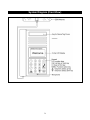
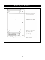
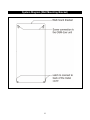
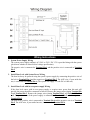
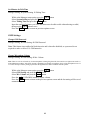
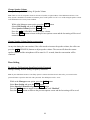
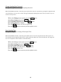
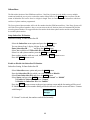
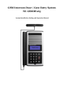
GSM Intercom Door / Gate Entry System
NC-GSMDE263
System Installation, Setting and Operation Manual
User Manual (NC-GSMDE263)
Please read this user manual completely before operating this system and keep it in a safe place for future reference.
TABLE OF CONTENTS
TABLE OF CONTENTS …………………………………………………………….
1~2
IMPORTANT SAFETY INSTRUCTIONS…………………………………………..
3
SYSTEM DIAGRAMS
Front View ……………………………………………………………………….
4
Back View ……………………………………………………………………….
5
Wall Mounting Bracket ………………………………………………………….
6
INSTALLATION
GSM Intercom Door / Gate Entry System……………………………………..…
7
Wiring Diagram & Wiring Instructions ……………………………………….....
8
OPERATION
Power ON/OFF …………………………………………………………………..
9
Manager Mode and Functions ……………………………………………………
9
Button Functions …………………………………………………………………
9
MANAGER SETTINGS
Change Manager Password ………………………………………………………
10
Store Manager Telephone Number ……………………………………………....
10
Set Minutes for Talk Time ……………………………………………………….
11
GSM SETTING
Change GSM Password ………………………………………………………….
11
Change Microphone Volume …………………………………………………….
11
Change Speaker Volume ……………………………………………………........
12
Change Speaker Volume During Conversation ………………………………….
12
DOOR SETTING
To Activate / Deactivate Door Strike by Password ………………………………
12
Change Opening Door Password …………………………………………………
13
Door Opening Time ………………………………………………………………
13
SUBSCRIBER ID NUMBER SETTING
Setup Subscriber ID Number …………………………………………………….
14
Enable or Disable the Subscriber ID Number ……………………………………
14
CONTACTING A SUBSCRIBER...………………………………………………….
15
OPEN THE DOOR REMOTELY …………………………………………………..
15
GO BACK TO “WELCOME!” SCREEN AUTOMATICALLY ………………….
16
SIM CARD ……………………………………………………………………………
16
CALL MANAGER …………………………………………………………………..
16
MASTER RESET…………………………………………………………………….
16
1
Thank you for purchasing the GSM Intercom Door / Gate Entry System. To ensure that you enjoy the full
capacity of this product, please read this user manual before proceeding. Be sure to keep this manual for future
reference in case any challenge or question should arise. We hope you enjoy your new GSM Intercom Door /
Gate Entry System.
IMPORTANT SAFETY INSTRUCTIONS
When using your GSM Intercom Door / Gate Entry System, basic safety precautions should always be followed
to reduce the risk of fire, electric shock and personal injury. Please read the following before using your
equipment.
1. Follow all warnings and instructions on the product.
2. Unplug the product before cleaning. Do not use liquid cleaners or aerosol cleaners. Use a damp cloth for
cleaning.
3. Do not use this product near water.
4. Do not allow anything to rest on power cords. Do not place this product in a location where the cords can be
stepped on or where someone can trip over them.
5. Do not use this product near an area where there is a potential of gas leaks or near any fumes that can be
explosive.
6. Do not place this equipment near or over a radiator or any other heat source.
7. Use ONLY the power adapter supplied with the system.
8. Do not overload the wall outlet or power cord where the power adapter is installed. This can result in fire or
electric shock.
9. This equipment is to be opened ONLY by a qualified service technician. There are no user serviceable parts
inside. Opening this equipment may expose you to dangerous voltage and other risks. Incorrect reassembly
of this equipment may result in electric shock.
10. Avoid spilling liquid on this equipment and do not insert any objects through the ventilation slots.
11. Avoid using this equipment during an electrical storm. There is a remote risk of electrical shock from
lighting.
12. Do not use this equipment other than for its purpose intended by the manufacture. Use ONLY the equipment
provided by the manufacturer.
2
System Diagram (Front View)
3
System Diagram (Back View)
4
System Diagram (Wall Mounting Bracket)
5
INSTALLATION
GSM Intercom Door / Gate Entry System
1. Take the wall mount bracket from the package and screw it on proper place. (As shown in Step 1 &
2 below)
2. Open the bottom cover of door unit and pass the wires through wire-hole. Then, refer to the
3.
4.
5.
6.
“Wiring Diagram and Wiring Instruction” to connect wires and insert the SIM card to SIM card
slot. (As shown in Step 3)
Put the bottom cover back. (As shown in Step 4)
Place door unit on the fixed wall mount bracket. (As shown in Step 6 & 7)
Put the acrylic cover on the door unit when door unit has been screwed. (As shown in Step 8 & 9)
Plug the AC adapter into the AC outlet; the door unit will go into standby condition.
WARNING: Only use the original power adapter supplied. Using any other adapter might damage the
door unit and cause a risk of electric shock.
6
Wiring Instructions
1. System Power Supply Wiring
The system power supply (adapter) AC 120V or 230V / DC 13V is provided along with the system
(please note whether it can meet local voltage specification).
The negative wire is connected to Terminal Pin 1 and the positive wire is connected to Terminal
Pin 2.
2. Install Door Lock with System Power Wiring
The door lock may be powered using the system’s power supply by connecting the positive wire of
the lock to Terminal Pin 4 and the negative to Terminal Pin 5. The ACK wire, if your strike has
one, is connected to Terminal Pin 6. (The system will supply 12 volts DC at 1000 mA)
3. Install Door Lock with its own power supply Wiring
If the door lock comes with its own power supply or requires more power than this unit will
provide, the power should be connected as follows. Remove the jumper wires joining Terminal Pin
2 and Terminal Pin 3. Remove the jumper wires joining Terminal Pin 1 and Terminal Pin 5 as
well. The positive wire of the power supply is connected to Terminal Pin 3 and the negative to
Terminal Pin 5.
The door lock’s positive wire is connected to Terminal Pin 4 and the negative wire is to Terminal
Pin 5. The ACK wire, if your strike has one, is connected to Terminal Pin 6.
7
OPERATION
z Before operation: Please make sure the GSM Intercom Door / Gate Entry System is installed
correctly. Please also study all key functions before use.
Power ON/OFF
Turn the power ON
Insert the plug of the power adapter into the DC power jack of door unit and the other end into an
AC power outlet.
When the power is on, the system will emit a “beep” sound, show “GSM Intercom Door / Gate
Entry System” and software version on screen, “Search Network” for few second, and then show
“Welcome!"
GSM Door Phone
Version v1.18
Search Network
Welcome!
Turn the power OFF
Turn off the door unit by unplugging the power adapter from the AC power outlet.
Manager Mode and Functions
Note: The unit will be time out after 5 seconds if no buttons are pressed.
Press the MENU button, and the system will show "Hello! Manager!"
Hello! Manager!
"Password:______"
Password:
____
After entering default password "1234", press the CALL button to show the button functions as
below:
"CALL: Select/Save"
"C: Delete"
"MENU: Exit/Abort"
"▲/▼: Move cursor"
Press any button or after 6 seconds, it will show:
Manager
Subscriber
8
Manager Settings:
Under the Manager section, there are 3 main options: “System Setting”, “GSM Setting” and “Door
Setting”.
System Setting
GSM Setting
Door Setting
Change Manager Password
Manager Setting Æ System Setting Æ Change Password
Note: The Manager Password is the key to enter Programming Mode. Please make sure to keep the Manager Password in a
safe place. If you forget the Manager Password, you’ll have to do a Master Reset which will delete your saved phones
numbers and settings.
While at the Manager menu option, press the CALL button
Select System Setting and press the CALL button
Select Change Password and press the CALL button
Enter New password (must be 4 digits)
Enter password again to confirm and press the CALL button
Store Manager Telephone Number
Manager Setting Æ System Setting Æ Manager Phone#
Note: This will be the number that is called when the CALL button is pressed in standby mode.
While at the Manager menu option, press the CALL button
Select System Setting and press the CALL button
Select Manager Phone # and press the CALL button
With cursor on the 1, press the CALL button to enter phone number
Enter phone number with prefix and area code, then press the CALL button to save.
(If you enter a number incorrectly, use the arrow keys to move forward or backward. The C button will clear a
digit you do not want.)
Press the MENU button to return to previous options screen
9
Set Minutes for Talk Time
Manager Setting Æ System Setting Æ Talking Time
While at the Manager menu option, press the CALL button
Select System Setting and press the CALL button
Select Talking Time and press the CALL button
Input the number of minutes you’d like the intercom to be able to talk without having to redial,
then press the CALL button to save.
Press the MENU button to return to previous options screen
GSM Settings
Change GSM Password
Manager Setting Æ GSM Setting Æ GSM Password
Note: This feature is not utilized in North America and is therefore disabled, as a password is not
required to make a call on U.S. GSM networks.
Change Microphone Volume
Manager Setting Æ GSM Setting Æ Mic. Volume
Note: There are 9 levels of sensitivity for the microphone volume going from left (least sensitive) to right (most sensitive).
If the GSM Intercom Door / Gate Entry System is installed in an outdoor environment, please set the microphone level to 3
or 4. This can help to reduce picking up too much background noise and/or feedback from the speaker.
While at the Manager menu option, press the CALL button
Select GSM Setting and press the CALL button
Select Mic. Volume and press the CALL button
Press the ▲/▼ (UP/DOWN) buttons to adjust volume.
Press the MENU button to return to the previous options screen and the last setting will be saved
automatically.
10
Change Speaker Volume
Manager Setting Æ GSM Setting Æ Speaker Volume
Note: There are 9 levels of speaker volume level from left (softest) to right (loudest). If the GSM Intercom Door / Gate
Entry System is installed in an outdoor environment, please set the speaker level to 5 or 6. Avoid setting the speaker volume
to the maximum level as it may cause feedback.
While at the Manager menu option, press the CALL button
Select GSM Setting and press the CALL button
Select Speaker Volume press the CALL button
Press the ▲/▼ (UP/DOWN) buttons to adjust volume.
Press the MENU button to return to the previous options screen and the last setting will be saved
automatically.
Change Speaker Volume During conversation
At any time during the conversation, if the caller needs to increase the speaker volume, the caller can
press the ▲/▼ (UP/DOWN) buttons to adjust speaker volume. The screen will show the current
speaker volume and the microphone will be mute for 1.5 seconds, then the conversation will be
continued.
Door Setting
To Activate / To Deactivate Open Door lock by Password
Manager Setting Æ Door Setting Æ Open by Password
Note: If your GSM Intercom Door / Gate Entry System is connected with an electric door strike, you can activate the
password feature to open the door lock with a password. The default password is “1234”.
While at the Manager menu option, press the CALL button
Select Door Setting and press the CALL button
Select Open by Password and press the CALL button
Press the CALL button to toggle between “Enabled” and “Disabled”
Press the MENU button to return to the previous options screen and the last setting will be saved.
11
Change Opening Door Password
Manager Setting Æ Door Setting Æ Opening Password
Note: This GSM Intercom Door / Gate Entry System system allows the user to open door by pressing the 4 digits Password
Code. This feature is for easy access control. We suggest changing the Opening Door Password every month or every two
weeks for security reason.
While at the Manager menu option, press the CALL button
Select Door Setting and press the CALL button
Select Opening Password and press the CALL button
Enter password (must be 4 digits)
Press the CALL button to save the new password
Press the MENU button to return to previous options screen
Door Opening Time
Manager Setting Æ Door Setting Æ Door Open Time
Note: This GSM Intercom Door / Gate Entry System allows the user to set how long the door dock will be open for. In
some situations, the user might need more time to reach from the door phone unit to the locked main gate. We suggest the
user to set enough time to allow him/her to walk without hurry.
While at the Manager menu option, press the CALL button
Select Door Setting and press the CALL button
Select Door Open Time and press the CALL button
Enter the number of seconds (from 03 to 99 seconds)
Press the CALL button to save
Press the MENU button to return to previous options screen
12
Subscriber:
The Subscriber function of the GSM Intercom Door / Gate Entry System gives the ability to set up multiple
tenants and enable the user to press a subscriber number followed the by the CALL button to connect with the
tenant. A Subscriber ID # can be from 1 to 6 digits in length. There is a maximum of 263 subscribers which can
each have 2 phone numbers programmed.
The first registered phone number will be the first number that the GSM Intercom Door / Gate Entry System will
call. If the first registered number is busy or no one answers the call, the door phone will automatically dial the
second registered number. We suggest that the first number be the home phone number and the second number
be a mobile phone number.
Setup Subscriber ID Number
Subscriber Setting Æ Enter Subscriber ID
Select the Subscriber menu option and press the CALL button
You can choose from 1 digit to 6 digits for the Subscriber ID.
Enter Subscriber ID “_____” and press the CALL button
Select Yes to add the new Subscriber ID and press the CALL button
Select 1 to add a phone number press the CALL button
Enter a phone number with area code, then press the CALL button to save
Press the MENU button to exit
Enable or Disable the Subscriber ID Number
Subscriber Setting Æ Enter Subscriber ID
Select Subscriber menu option and press the CALL button
Enter the Subscriber ID # in which you wish to Enable or Disable
Select Enter Subscriber ID # and press the CALL button
Select Status: and press the CALL button to select “Normal” or “Inhibit”
To Enable the Subscriber ID select “Normal”
To Disable the Subscriber ID select “Inhibit”
Press the MENU button to return to the previous options screen and the last setting will be saved.
If “Inhibit” is selected, the number dialing will be not allowed. And, the screen will show “Contact
with Manager”.
Contact with
Manager
If “Normal” is selected, the number can be dialed normally.
13
Contacting a Subscriber
At the "Welcome!" screen, enter User ID number (from 1 ~ 999999) and then press the CALL button.
If the ID exists, the system will start dialing and show “Calling…” on the screen. When the phone is
connected, the screen will show “Talking”.
Calling- - -
Talking- - Incorrect!
If the ID does not exist, the screen will show “Incorrect!”.
If the ID exists, but there is no number assigned, the screen will show “Calling…”, but will never
connect and time out after 3 minutes. In order to avoid this problem, please make sure to input the
phone number on each User ID.
Calling- - -
Time’s Up!
If the dialing attempt fails, the screen will show “No dial tone” and go back to “Welcome!”.
No dial tone!
Welcome!
If the call is not answered within a 1 minute, the screen will show “No Answer” and go back to
“Welcome!”.
No answer!
Welcome!
During a conversation, if the other party hangs up or the line is cut, the screen will show “No
Carrier” and go back to “Welcome!”.
No carrier!
Welcome!
During a conversation or while dialing, pressing
conversation.
MENU
or
C
button will stop the
Open the Door Remotely
During a conversation, the called party can press the * button to open the door. The door-open
time can be set by user. The default setting is 3 seconds.
14
Go Back to “Welcome!” Screen Automatically
If the manager password has been entered and then no button is pressed within 30 seconds, the
screen will go back to the “Welcome!” screen
If a Subcriber ID is entered and no button is pressed within 6 seconds, the screen will go back to
the ”Welcome!” screen.
If no button is pressed within 30 seconds, while in the Manager or Subscriber options, the screen
will go back to the “Welcome!” screen.
SIM Card
If the SIM card is not inserted, the screen will show “SIM not inserted” when the system is turned
on.
SIM not Inserted
Call Manager
If a “Manager Phone #” has been programmed, the system will directly dial this number when the
visitor presses the CALL button at the “Welcome!” screen.
If a “Manager Phone #” is not stored, no action will result by pressing the CALL button
Screen Saver
To save power and promote the longevity of the screen, after 30 seconds of standby, the screen
will turn off automatically.
Master Reset
The following sequence will bring the unit back to factory defaults. Please note that this will erase
all passwords, phone numbers, and subscribers.
At the “Welcome” screen, press C, UP, UP, UP, DOWN, DOWN, DOWN, CALL buttons in
sequence. It will say “Initial System Please Wait…”, then all is back to square one.
15