1
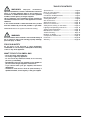
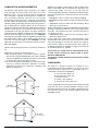
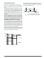
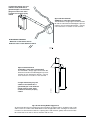
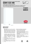
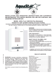
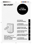
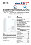
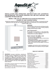
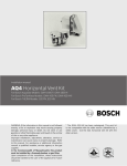
Water heaters for use with Natural and L.P.G.
GWH 425 EF
Flow Modulated with Electronic Ignition and Power Venting
Suitable for heating potable water only - Not approved for space heating purposes
(Intended for variable flow applications with steady cold water inlet temperatures)
PRO TANKLESS
GWH-425-EF-N
GWH-425-EF-L
6 720 607 017 US (03.10) JS
Warning: If the information in this manual is not
followed exactly. A fire or explosion may result
causing property damage, personal injury or death.
Do not store or use gasoline or other flammable
vapor and liquids in the vicinity of this or any other
appliance.
Improper installation, adjustment, alteration,
service or maintenance can cause injury or
property damage. Refer to this manual. For
assistance or additional information consult a
qualified installer, service agency or the gas
supplier.
In the Commonwealth of Massachusetts this
product must be installed by a licensed plumber or
gas fitter.
Upon completion of the installation, these
instructions should be handed to the user of the
appliance for future reference.
What to do if you smell gas
• Close gas valve. Open windows.
• Do not try to light any appliance
• Do not touch any electrical switch; do not use any
phone in your building
• If you cannot reach your gas supplier, call the fire
department.
• Immediately call your gas supplier from a neighbor’s
phone. Follow the gas supplier’s instructions.
• Installation and service must be performed by a
qualified installer, service agency or the gas supplier.
TABLE OF CONTENTS
WARNING : Improper installation,
adjustment, alteration, service or maintenance can cause
injury or property damage. Refer to this manual. For
assistance or additional information consult a qualified
installer, service agency or the gas supplier.
Upon completion of the installation, these instructions
should be handed to the user of the appliance for future
reference.
In the Commonwealth of Massachusetts this product
must be installed by a licensed plumber or gas fitter.
FEATURING: Electronic Ignition and Power Venting
WARNING
If the information in this manual is not followed exactly. A
fire or explosion may result causing property damage,
personal injury or death.
Specifications ............................................................... Page 3
Rules for safe operation ............................................. Page 5
Locating the Heater .................................................... Page 5
Combustion Air Requirements .................................. Page 6
Mounting the Heater ................................................... Page 7
Venting the Heater ...................................................... Page 8
Gas Connections ...................................................... Page 11
Water Connections ................................................... Page 13
Electrical Connections ............................................. Page 14
Safety before turning on the heater ...................... Page 15
Lighting and Operating instructions ...................... Page 15
Setting water temperature ....................................... Page 15
Maintenance & Service ............................................ Page 16
Trouble Shooting .........................................................Page 17
Diagram of 425EF .................................................... Page 20
Components and Parts List ..................................... Page 21
Flowchart ..................................................................... Page 23
Warranty ...................................................................... Page 24
FOR YOUR SAFETY
Do not store or use gasoline or other flammable,
combustible or corrosive vapors and liquids in the vicinity
of this or any other appliance.
WHAT TO DO IF YOU SMELL GAS
- Close gas valve. Open windows.
- Do not try to light any appliance.
- Do not touch any electrical switch; do not use any
phone in your building.
- Immediately call your gas supplier from a neighbor’s
phone. Follow the gas supplier’s instructions.
- If you cannot reach your gas supplier, call the fire
department.
- Installation and service must be performed by a
qualified installer, service agency or the gas supplier.
2
6 720 607 017
Principle of Operation:
When a hot water faucet is opened, the flow of water through
the heater causes the gas valve to open. At the same time
a microswitch is activated which sends a spark to the pilot.
The flame sensor confirms that the pilot has been lighted
and allows the first two burners to ignite. The flame sensor
confirms correct activation and all burners ignite. The pilot
goes out. The power exhaust system runs as long as the
burners are on. The heat exchanger coils absorb the heat
generated by the burners and transfer heat to the water.
When the hot water faucet is shut off, the gas valve
automatically closes and the burners turn off, followed
immediately by the exhaust system. Your hot water faucet is
an ignition key to turn on the water heater, giving you control
over your hot water energy use. Every time you turn off your
hot water faucet, the energy consumption for hot water
returns to zero.
425 EF LP and 425 EF NG Specifications
FEATURES
Shipping Weight 50.6 LB
- Electronic Pilot Ignition
Net Weight 44 LB
- On/Off switch to activate system
2.0 GPM at 90° rise
- Power Venting with safety shutoff
4.0 GPM at 45° rise
- High Quality Materials for Long Working Life.
Min. Water Flow 1/2 gal/min
- Copper heating coils for endless supply of hot water.
120V/60Hz 1.2 Amps
- Burner output proportional to hot water flow demand for
maximum energy efficiency.
LP GAS Supply Pressure
(before 425 EF regulator)
min. 11” W.C.
max.14” W.C.*
Required LP GAS pressure at inlet
tap while 425 EF is operating:
10.5” W.C.
425EF NG
Gas input
425 EF LP
max. 130 000 Btu/hr 125 000 Btu/hr
min.
28 000 Btu/hr
28 000 Btu/hr
Water Connection 1/2” Thread fitting NPT
H x W x D 29 3/4” x 18 1/4” x 8 3/4"
Vent 4”
Gas Connection 1/2” NPT thread
Min. Water Pressure 18 Psi
Max. Water Pressure 150 Psi
- Safety flame sensor at pilot burner.
- Automatic overheating protection shut-off sensor.
- Stainless steel burners with stabilized blue flame.
- Built-in corrosion resistant power venter.
LP GAS Burner Manifold pressure while
425 EF is operating at maximum input: 9.9” W.C.
- Compact space saver: mounts on a wall with two hooks.
- Easily removable one-piece cover.
Natural Gas Supply Pressure
(before 425 EF regulator)
min.: 7” W.C.
max.: 14”W.C.*
Required Natural Gas Pressure at
inlet tap while 425 EF is operating:
5.7”W.C.
- Easy one person installation.
- Adjustable water flow restrictor to ensure that water flow
demand will not exceed the heating capacity of the heater.
Natural Gas Burner Manifold pressure while
425 EF is operating at maximum input: 5.38” W.C.
* Inlet gas pressure before 425 EF regulator must not
exceed this value. Pressure may need to be adjusted for
high altitudes, see page 11.
UNPACKING THE 425 EF HEATER
This heater is packed securely. The box includes one water connection fitting, a control knob with collar, a gas pressure
regulator, a pressure relief valve, an incandescent particle tray, two hooks for hanging the heater, this manual and a
warranty registration card. Do not lose this manual as there is a charge for replacement. Please complete and return
the enclosed warranty registration card. The FXHOOD horizontal vent terminator is supplied separately from the 425EF
water heaters. There is a set of installation instructions in the FXHOOD box.
6 720 607 017
3
FRONT VIEW
SIDE VIEW
MINIMUM INSTALLATION CLEARANCES FROM COMBUSTIBLE AND NON
COMBUSTIBLE MATERIALS FOR ALCOVE OR CLOSET INSTALLATIONS
MODEL 425 EF
TOP (A)
12 "
FRONT (B)
4"
BACK
0"*
SIDES
4"
FLOOR (C)
12 "
VENT DIAMETER
4"
* On a combustible wall surface the unit should be mounted away
from the wall to provide adequate clearance of the vent pipe.
See page 5 for instructions.
MODEL 425 EF
4
6 720 607 017
GENERAL RULES TO FOLLOW
FOR SAFE OPERATION
1. You should follow these instructions when you install your
heater. In the United States: The installation must conform
with local codes or, in the absence of local codes, the
National Fuel Gas Code ANSI Z223.1/NFPA 54.
In Canada: The Installation should conform with CGA
B149.(1,2) INSTALLATION CODES and /or local installation
codes.
2. Carefully plan where you install the heater. Correct
combustion air supply and flue pipe installation are very
important. If not installed correctly, fatal accidents can be
caused by lack of air, carbon monoxide poisoning or fire.
3. The place where you install the heater must have
enough ventilation. The National Fire Codes do not allow
gas fired water heater installation in bathrooms,
bedrooms or any occupied rooms normally kept closed.
See the section below on locating the heater.
4. You must install your heater so that the venting complies
with all requirements. See section on Venting the Heater,
pages 6 and 7.
5. The appliance must be disconnected from the gas supply
piping system during any pressure testing at pressures in
excess of 1/2 Psig (3.5 kPa).
The appliance must be isolated from the gas supply piping
during any pressure testing of the gas supply piping system
at test pressures in excess of 1/2 Psig (3.5Kpa). The
appliance and its gas connection must be leak tested before
placing the appliance in operation.
6. Keep water heater area clear and free from combustibles
and flammable liquids. Do not locate the heater over any
material that might burn. Do not install heater over carpeting.
7. Correct gas pressure is critical for the optimum
operation of this heater (see specifications on page 2 and
chart on page 9). Gas piping must be sized to provide the
required pressure at the maximum output of the heater.
Check with your local gas supplier, and see the section on
connecting the gas supply.
8. Should overheating occur or the gas supply fail to shut
off, turn off the gas supply at the manual gas shut off valve
on the gas line.
The heater may still operate even when improperly vented.
It will, however, be less efficient and could eventually damage
the heater. It could even result in human sickness or death
due to oxygen deprivation and carbon monoxide poisoning.
Before installing the unit, be certain you have the correct
heater for your type of Gas – Propane or Natural Gas.
Identification labels are found on the shipping box, and on
the rating plate which is located on the right side panel of
the cover. Also, each burner orifice is stamped with a number
(79 for LPG and 120 for Natural Gas).
Follow the guidelines below:
1. National building codes require that you do not install
this appliance in bathrooms, bedrooms, unvented closet
or any occupied rooms normally kept closed.
2. Simultaneous operation of other appliances such as
exhaust fans, ventilation systems, clothes dryers, fireplaces
or wood stoves could create a vacuum effect in your home
which could cause dangerous combustion by-products to
spill back into your home rather than venting to the outside
through the flue. Confirm that your 425 EF is venting
properly when all these other appliances are running. See
page 6 to test venting performance.
Do not obstruct the flow of combustion air to the
appliance. This appliance is power vented and uses room
air. Note: Electrical power is required to operate the power
exhaust. Proper air supply to the appliance is essential.
If installed near a clothes dryer it is very important that the
dryer be properly vented. Failure to properly vent a dryer
could result in a gradual accumulation of lint on the water
heater fin coils and burners, leading to a dangerous condition
of vent blockage and poor, unsafe combustion.
3. Your hot water lines should be kept short to save energy.
It is always best to have hot water lines insulated.
WARNING: DO NOT INSTALL IN AN AREA WHERE
IT COULD FREEZE. This heater is neither designed for
nor approved for outside installation. Drain the heater
entirely if freezing temperatures are anticipated in area where
heater is installed by disconnecting both the inlet and outlet
water connections from the heater (disconnect the outlet
flex line from where it connects to the copper heat
exchanger). Additionally, remove the drain plug under the
water valve. See Fig 1.
9. Do not use this appliance if any part has been under
water. Immediately call a qualified service technician to
inspect the appliance and to replace any part of the control
system and any gas control that has been under water.
10. When installed, the appliance must be electrically
grounded in accordance with local codes or, in the absence
of local codes, in accordance with the National Electrical
Code ANSINFPA 70 and/or the CSA 22.1 Electrical Code.
PROPER LOCATION FOR INSTALLING YOUR
HEATER
Carefully select the location of your new heater. For your
safety and for proper heater operation, you must provide an
abundant supply of combustion air and a proper venting
installation.
6 720 607 017
Fig. 1 - Water heater drain plug
WARNING: Flammable materials, gasoline,
pressurized containers, or any other items or articles that
are potentially fire hazards must NOT be placed on or
adjacent to the heater. The appliance area must be kept
free of all combustible materials, gasoline and other
flammable vapors and liquids.
5
COMBUSTION AIR REQUIREMENTS
The 425 EF water heater holds cold water in its copper
heat exchanger and brass water valve when not in use.
Because of this, any cold air that comes in through the
unit’s vent pipe is capable of freezing these components.
This Installation Manual specifies the vent length
requirements and the amount of combustion air required for
this unit. When all requirements are followed, the unit will
operate properly and safely. However, there may still be a
risk of freezing due to negative draft if all the combustion
appliances in the area are not being supplied with a sufficient
amount of make-up air. A wood stove or furnace may pull
combustible air through the 425 EF vent pipe, leaving the
cold infiltrating air capable of freezing the cold water in the
425 EF heat exchanger. To prevent this the FXHOOD
horizontal vent terminator, which is supplied separately with
the water heater, needs to be installed on the end of the
horizontal vent run (see page 9). The FXHOOD is a CSA
approved vent terminator for the 425 EF and has a built in
back draft flapper.
Observe the following instructions concerning combustion
air.
Appliances located in unconfined spaces:
a) An unconfined space is one whose volume is greater
than 50 cubic feet per 1000 Btu per hour of the combined
rating of all appliances installed in the space. That would
be 6500 cubic feet for the 425 EF alone.
b) In unconfined spaces in buildings of conventional frame,
masonry, or metal construction, infiltration is normally
adequate to provide air for combustion, ventilation, and
dilution of flue gasses.
Air Vents
(10 ¾ X 10 ¾ in. each)
425 EF
425 EF
Appliances located in confined spaces: The confined space
must be provided with two permanent openings, one
commencing within 12 inches of the top and one
commencing within 12 inches of the bottom of the enclosure.
Each opening must have a minimum free area of one square
inch per:
— 1000 Btu/hr if all air is taken from inside the building.
— 2000 Btu/hr if all air is taken from the outside by horizontal
ducts.
— 4000 Btu/hr if all air is taken from the outside by direct
openings or vertical ducts.
Or the confined space must be provided with one permanent
opening or duct that is within 12 inches of the ceiling of the
enclosure. This opening must have a minimum free area of
one square inch per:
— 3000 Btu/hr if all air is taken from the outside by a direct
opening or vertical duct.
Louvers, grills and screens have a blocking effect. If the
effective free area is not known, assume it is 20 % to 25%
of the total opening for wood louvers and 60 % to 75% for
metal louvers. Refer to the National Fuel Gas Code for
complete information. In buildings of tight construction all
air should be taken from outside.
This product is not approved for manufactured homes
(mobile home), recreational vehicles (RV) or boats.
Reference ANSI Z21.10.3.
This product is neither designed or approved for outside
installations.
CLEARANCES
The 425 EF is design certified for installation on a
combustible wall and for installation in an alcove or closet
with the minimum clearances to combustible and non combustible construction listed below
A. Top 12 inches (305 mm)
B. Front 4 inches (102 mm)
C. Back 0 inches*
D. Sides 4 inch (102mm)
E. Bottom 12 inches (305 mm)
* On a combustible wall surface the unit should be mounted
away from the wall to provide adequate clearance of the
vent pipe. Clearance from the vent pipe is dependent upon
the clearance rating of the venting material used. See
VENTING section.
Air Vents
(5 ½ X 5 ½ in. each)
6
6 720 607 017
MOUNTING INSTALLATION
The 425 EF is design certified for mounting on a wall.
Secure the two L shaped hooks, which are provided with
heater, to a wall surface. Place them 13 ¼” apart as shown
in Fig 2.
Do not install this appliance on a carpeted wall or over floor
covering which is combustible, such as carpet. The heater
must be mounted on a wall using appropriate anchoring
materials. If wall is a stud wall sheathed with plasterboard, it
is recommended that support board(s) either 1x4’s or 1/2"
(minimum) plywood first be attached across a pair of studs
and then the heater should be attached to the support boards.
See Fig 2.
NOTE: Additionally the 425 EF should be spaced away
from any combustible wall surface to provide the
necessary clearance that the venting material specifies
must be maintained between the vent pipe and a
combustible surface. See VENTING section. Also, review
the FXHOOD horizontal vent terminator instruction sheet
(provided with the FXHOOD) prior to installation.
In earthquake-prone zones, CEC recommends that installers
use a large washer and lag screw through the existing holes
used to hang the heater to affix the upper third of the heater
to the mounting board. To affix the lower third of the heater,
CEC recommends that two new holes be drilled in the
heater’s frame, each one 16 inches below the top two holes,
and that washers and lag screws be used to secure the
lower portion of the heater to a spacing board.
Expansion and contraction of piping due to changing water
temperature in the pipes imparts movement to the heater
which, if mounted directly to a brittle, friable board, such as
plasterboard, can cause failure of mounting.
The incandescent particle tray (shipped loose in the carton
with the water heater) must be attached at the bottom of
the water heater front cover at the time of installation. Use
the screws provided. See figure 3.
SCREWS
INCANDESCENT PARTICLE TRAY
Fig. 3 - Incandescent Particle Tray Illustration
WALL STUDS
13 ¼”
SUPPORT BOARD
1” X 4”
SPACE BOARD
Fig. 2 - Mounting the Heater
6 720 607 017
7
VENTING
WARNING: Do not reduce the vent pipe size and
do not common vent with any other vented appliance or
stove.
This appliance must be vented horizontally to the outside
with a sealed 4” single wall vent pipe. The appliance’s flue
gasses are under positive pressure and must travel through
a single wall 4” pipe that is sealed gas tight. The 4” single
wall vent pipe can be either stainless steel (AL29-4C) or
galvanized steel with at least 26 gauge. CEC recommends
the use of stainless steel vent pipe (which is equipped with
sealing gaskets) for ease of installation and durability. When
using galvanized vent pipe a minimum of 4 sheet metal
screws per connection must be installed and all seams must
be sealed with an approved high temperature silicone
sealant. The vent system must be gas tight. See Fig. 4 for
suggested venting installation diagrams.
The 425EF shall not be vented in combination with any
other appliance. This appliance may only be vented
horizontally with a dedicated sealed single wall vent. The
425EF shall not be vented into masonry chimneys or existing
vertical vents of any material.
CAUTION: 425EF vent system must be installed by a qualified
agency in accordance with these instructions. If improperly
installed a hazardous condition such as explosion or Carbon
Monoxide poisoning could result. Controlled Energy
Corporation will not be responsible for improperly installed
appliances.
Establish vent clearances that comply with vent
manufacturer’s specifications. In all cases follow local codes.
See table below.
The vent diameter must be 4”. The appliance should be
located as close to the point of termination as possible (see
Fig. 5 for locating the terminator). The vent system should
be as straight and short as possible. The vent pipe must be
4” single wall stainless steel (AL29-4C) or galvanized steel
pipe of 26 minimum gauge. Maximum vent length is 15
feet (4.6 m) with two 90-degree elbows. Subtract 5 feet
from the total vent length for each additional 90-degree
elbow used. No more than four 90-degree elbows may be
used. Any short vertical portion of vent pipe used in the
vent system shall be considered part of the allowable 15
feet (4.6 m) maximum run. Support the vent run at 4 foot
intervals with overhead hangers. Horizontal sections of vent
must rise ¼” for every foot of horizontal length. Any vent
section greater than 45 degrees is considered and elbow.
Note: Single wall pipe should not be used in concealed,
unoccupied or unheated locations. Listed thimbles or collars
are necessary to pass through wall partitions. If the vent
system passes through combustible areas where the vent
clearance requirements cannot be maintained, it is
permissible to chase straight sections of sealed 4 inch single
wall vent through 5 inch (or greater) Type-B vent. The
distance to combustibles using this chase technique is 1
inch. Note: Type-B vent should never be used as the actual
vent system for the 425EF, as it is not gas tight.
Freeze Warning:
As mentioned on Page 6, negative air pressure in cold
climates will cause a reverse airflow in the vent system that
can freeze and damage the 425 EF heat exchanger when
not in use. To prevent this the FXHOOD horizontal vent
terminator, which was supplied separately with the water
heater, needs to be installed on the end of the horizontal
vent run (see page 9). The FXHOOD is a CSA approved
vent terminator for the 425 EF and has a built in back draft
flapper.
Flue Gas Sensor:
The 425 EF is equipped with a Flue Gas Sensor; it’s mounted
on the left side of the draft diverter (Flue Gas Sensor - #33
on page 21). Before leaving the installation site verify proper
Flue Gas Sensor operation by temporarily blocking
termination outlet. Once blocked then operate the heater,
the unit should shut down within 1-3 minutes when the flue
gases are blocked. You must reset the electrical power to
the heater after this safety test has been conducted,
otherwise the unit will not operate.
The flue gas exhaust temperature on the 425 EF is 356°F (180°C)
Venting Material
Options
Exhaust vent
diameter
Exhaust vent maximum
distance
Single wall stainless
steel (AL29-4C)
sealed vent pipe
4 inch
15 feet (4.6 m) with two
elbows. Less 5 feet for
each additional elbow.
Single wall galvanized
vent pipe (min. 26
gauge and sealed
with high temperature
silicone)
4 inch
15 feet (4.6 m) with two
elbows. Less 5 feet for
each additional elbow.
Clearances
from venting
material
Vent pipe within an
unenclosed space
Vent pipe within an
enclosed space
*See manufacturer's
specifications
*See manufacturer's
specifications
6 inches
NOT PERMISSIBLE
*Stainless steel (AL29-4C) vent pipe manufacturer's are Z-Flex, Protech and Heat Fab. The manufacturer's specified clearances
are identified on the venting material. NOTE: clearance distances are variable depending if the vent pipe is installed in an
enclosed or unenclosed space, the exhaust flue gas temperature and the orientation of the vent pipe.
8
6 720 607 017
4”single wall venting only. Use
stainless steel (AL29-4C) or
galvanized pipe of 26 minimum
gauge must be used. Each
connection must be properly
sealed.
Approved Vent Terminal
(FXHOOD or other approved terminal)
The FXHOOD is design approved with the 425
EF and has a built in back draft flapper to prevent
negative air from freezing the 425 EF – see Fig.
5 for restrictions in location of vent terminal.
HORIZONTAL SIDE WALL
* Maximum 15 feet with 2 elbows.
Deduct 5 feet for each additional elbow.
4”single wall venting only. Use
stainless steel (AL29-4C) or
galvanized pipe of 26 minimum
gauge must be used. Each
connection must be properly
sealed.
G181_274
Approved Vent Terminal
(FXHOOD or other approved terminal)
The FXHOOD is design approved with the 425
EF and has a built in back draft flapper to prevent
negative air from freezing the 425 EF – see Fig.
5 for restrictions in location of vent terminal.
Fig 4: Some Venting Guide Suggestions
An approved side wall vent terminal must be used when the water heater is vented through a side
wall. Locate in accordance with ANSI Z223.1 and local applicable codes. See Fig 5 for restrictions
in location of vent terminal in relation to opening doors and windows, grade, and forced air inlets.
Be certain that snow and ice will not interfere with the vent.
6 720 607 017
9
The approved vent terminal must be installed so that flue gases will not jeopardize people, overheat combustible structures
or enter into buildings, and so that proper clearances are maintained (See Fig 5).
a) The vent terminal shall not be less than 7 feet above a public walkway.
b) The vent terminal shall terminate at least 3 feet above any (mechanical) air inlet within 10 feet.
c) The vent terminal shall not be within a 6-foot radius from a gas meter or regulator.
d) The vent terminal shall be a minimum of 6 feet from any combustion air inlet.
e) The vent terminal shall terminate from an opening window, at least 4 feet below or 4 feet horizontally from the
opening.
f) The vent terminal shall terminate from a door, at least 1 foot above and 4 feet horizontally from the door.
g) The vent terminal shall not be less than 3 feet from an adjacent building.
h) The vent terminal shall not be less than 1 foot above grade.
N
MI
1’
N
MI
4’
VENT HOOD MUST
BE MOUNTED ONE FOOT MINIMUM
ABOVE DOORS AND WINDOWS
SO
FF
IT
VENT HOOD
N
MI
1’
N
MI
4’
VENT HOOD MUST BE
MOUNTED FOUR FEET AWAY
FROM DOORS AND WINDOWS
N
MI
4’
D
CE
OR 10’
F
Y
N
AN THI
VE WI
O
T
AB NLE
3’
I
AIR
N
MI
4’
VENT HOOD MUST
BE MOUNTED FOUR FEET MINIMUM
BELOW WINDOWS
7’ M
PU INIM
BL
IC UM A
WA BO
LK VE
WA
Y
T
E
OO AD
E F E GR
N
O OV
AB
Fig 5: Side wall exit locations for mechanical draft vent terminals
10
6 720 607 017
GAS LINE SIZING
GAS CONNECTIONS
NOTE: The 425 EF is supplied with a gas pressure
regulator that must be installed on the heater before
attaching the gas supply line. See figure 6. Failure to
install the gas regulator as shown in figure 6 will be a
violation of CSA certification of the unit. The regulator
supplied with the heater is preset for the gas shown on
the rating plate to the correct pressure. It is an appliance
level regulator designed for (low inlet) pressure (less
than 1/2 Psig or 15” W.C.) DO NOT connect to an
unregulated or high pressure propane line or to a high
pressure commercial natural gas line.
GAS INLET PIPE
PRESSURE TAP
PLASTIC CAP
APPLIANCE PRESSURE
REGULATOR
(with directional arrow on
reverse side pointing upward)
Fig. 6 - Appliance pressure regulator
(with directional arrow on reverse side pointing up)
GAS LINE SIZING
The pressure regulator provided with the heater is adjusted
to deliver the proper gas pressure (as indicated on the rating
plate and in the manual for altitude up to 2000 feet (660
meters) above sea level. On appliances being installed above
2000 ft (660 meters) elevation, the inlet gas pressure should
be set at installation to the value shown below.
-It is strongly recommended that the Natural Gas pipe
be Black Iron pipe the entire distance from the outside
meter to the inlet of the 425 EF regulator. 1/2” Black Iron
pipe up to 10 feet, 3/4” Black Iron pipe up to 40 feet and
1” Black Iron pipe up to 125 feet distances. Flex line tubing
is NOT recommended, but if used then oversize it.
-It is strongly recommended that the LP Gas pipe be
semi-rigid copper or Black Iron pipe from the outside
regulator to the inlet of the 425 EF regulator. For semirigid copper piping: 5/8” up to 20 feet and 3/4” up to 50
feet distances. For Black Iron piping: 1/2 “ up to 30 feet
and 3/4” up to 150 feet distances. Flex line tubing is NOT
recommended, but if used then oversize it.
THESE FIGURES ARE FOR 425 EF SUPPLY ONLY, ALL
OTHER APPLIANCES IN THE BUILDING WILL NEED TO
BE INCLUDED IN THE PIPE SIZING.
National Fuel Gas Code requires that a sediment trap (drip
leg) be installed on gas appliances not so equipped. The
drip leg must be accessible and not subject to freezing
conditions. Install in accordance with the recommendations
of the serving gas supplier.
WARNING: The heater must be disconnected from
the gas supply piping system during any pressure testing of
that system at test pressures in excess of .5 psig.
The water heater must be isolated from the gas supply piping
system by closing the manual shutoff valve during any
pressure testing of the gas supply piping system at test
pressures equal to or greater than .5 psig.
The water heater, including the pressure regulator provided
with it, must not be operated at gas supply pressures in
excess of .5 psig. If overpressure has occurred, such as
through improper testing of the gas lines or malfunction of
the supply system, the gas valve and regulator must be
checked for safe operation.
When your connections are made, check for gas leaks at
all joints (not just the ones you made). Apply some soapy
water to all gas fittings and gas valve. Soap bubbles are a
sign of a leak.
NOTE: Do not apply soap solution to pilot filter screen or
pilot orifice area. If you have a leak, shut off the gas. After
verifying that required gaskets are in place, tighten
appropriate fittings to stop leak. Turn the gas on and check
again with a soapy solution. Never test for gas leaks using
a match or flame.
NOTE: The gas pressures specified below refer to
pressures taken at the pressure tap on the gas inlet pipe
just above the regulator (See Fig 6). These readings
should be taken while the heater is operating at full input
— i.e. maximum water flow with the temperature dial
selector turned all the way clockwise.
MAXIMUM INLET GAS FLOW PRESSURE SETTINGS
Altitude
0' - 2.000 ft
2.000 ft - 4.500 ft
Natural Gas
inches W.C:
5.7"
4.6"
Liquid Propane
inches W.C:
10.5"
8.4"
Above 4.500 ft consult your local gas provider.
6 720 607 017
11
GAS PIPING, CONNECTIONS
Before connecting the gas supply, check the rating plate on the right side of the front cover to be sure that the heater is
rated for the same gas to which it will be connected.
In the United States: The installation must conform with local codes or, in the absence of local codes, the National Fuel
Gas Code ANSI Z223.1/NFPA 54.
In Canada: The Installation should conform with CGA B149 INSTALLATION CODES and /or local installation codes.
GAS LINE SIZING
FOR NATURAL GAS
Follow boxed numbers for piping just one 425 EF
(example: 3/4” B.I. Natural Gas pipe for 30 ft. will handle
152,000 btu’s). For multiple appliances combine the total
btu input load and then refer to applicable chart below.
Maximum Capacity of pipe in Cubic Feet of Gas per Hour
for Gas Pressure of 0.5 Psig or less and a Pressure drop of
0.3 in Water Column.
(Based on a 0.60 Specific Gravity Gas) Btu numbers given
in thousands.
Nominal
Iron
Le ngth of Black Iron Pipe , Fe e t
Pipe
Internal
Size,
Diameter
inches inches
10
20
30
40
50
60
70
80
90
100
125
150
175
200
1/4
0.364
32
22
18
15
14
12
11
11
10
9
8
8
7
6
3/8
0.493
72
49
40
34
30
27
25
23
22
21
18
17
15
14
1/2
0.622
132
92
73
63
56
50
46
43
40
38
34
31
28
26
3/4
0.824
278
190
152
130
115
105
96
90
84
79
72
64
59
55
1
1.049
520
350
285
245
215
195
180
170
160
150
130
120
110
100
1 1/4
1.380
1050
730
590
500
440
400
370
350
320
305
275
250
225
210
1 1/2
1.610
1600
1100
890
760
670
610
560
530
490
460
410
380
350
320
2
2.067
3050
2100
1650 1450
1270 1150 1050
990
930
870
780
710
650
610
2 1/2
2.469
4800
3300
2700 2300
2000 1850 1700
1600 1500 1400
1250
1130
1050
980
3
3.068
8500
5900
4700 4100
3600 3250 3000
2800 2600 2500
2200
2000
1850 1700
4
4.026
17,500 12,000 9,700 8,300
7,400 6,80 6,200 5,800 5,400 5,100 4,500
4,100 3,800 3500
FOR LP GAS
Maximum Capacity of Pipe in Thousands of
BTU per Hour of Undiluted Petroleum Gases
(at 11 inches Water Column Inlet Pressure)
(Based on a Pressure Drop of 0.5 Inch Water Column).
Maximum Capacity of Semi-Rigid
Tubing in Thousands of BTU per Hour of
Undiluted Liquified Petroleum Gases (at 11
inches Water Column Inlet Pressure)
(Based on a Pressure Drop of 0.5 Inch Water
Column)
Nominal
Black Iron Pipe
Iron Pipe
Length of Pipe, Feet
Size,
10
60
70
80
90
100
125
150
1/2
275 189 152
129 114 103
96
89
83
78
69
63
132
Inches
20
30
40
50
3/4
567 693 315
267 237 217 196 185 173
162
146
1
107 732 590
504 448 409 378 346 322
307
275
252
1 1/4
220 149 121
103 913 834 771 724 677
630
567
511
1 1/2
330 229 185
155 141 127 118 108 102
976
866
787
2
622 433 346
299 264 239 220 204 192 1811 1606 1496
Copper
Length of Tubing, Feet
Outside
Diameter,
Inch
10
20
30
40
50
60
70
80
90
100
3/8
39
26
21
19
_
_
_
_
_
_
1/2
92
62
50
41
37
35
31
29
27
26
5/8
199 131
107
90
79
72
67
62
59
55
3/4
329 216
181 145
131
121 112 104
95
90
7/8
501 346
277 233
198
187 164 155 146 138
* Source National Fuel Gas Code NFPA 54, ANSI Z223.1 - No
Additional Allowance is necessary for an ordinary number of fittings
12
6 720 607 017
Connecting the pressure relief valve (PRV)
WATER CONNECTIONS
Install the heater centrally in the building if possible and
make hot water piping runs as short as possible When facing
the heater, the cold water inlet will be on the right and the
hot water outlet on the left..
Although water piping throughout the building may be other
than copper, copper or galvanized piping should be used
when connecting to the heaters ½” male NPT flex connectors
(follow local codes if more stringent). Plastics or other PEX
type plumbing line materials are not suitable for connecting
directly to the water heater. Keep water inlet pipe to no less
than ½” (19.05mm) diameter to allow the full flow capacity.
If the cold and hot connections to the heater are reversed,
the heater will not function.
The 425 EF is provided with one flexible type connector
that must be connected to the cold inlet fitting of the water
valve as shown in Fig. 7. The union end of the flexible
connector should be attached to the rear inlet port of the
water valve with the supplied washer gasket. No pipe dope
or thread tape is to be used at this joint. The ½” flexible hot
water outlet line is supplied attached to the heater.
Be certain there are no loose particles or dirt in the piping.
Blow out or flush the lines before connecting to the water
heater. Full port valves should be installed on both the cold
water supply and hot water outlet lines to facilitate servicing
the heater (see Fig. 7). For installation on a private well
system with the use of a pressure tank, the lowest pressure
range setting recommended is 30-50 psi (2.07-3.45 bar).
The listed pressure relief valve supplied with the heater must
be installed at the time of installation. Should a discharge
line be added to the PRV no valve is to be placed between
the PRV and the heater. No reducing coupling or other
restriction may be installed in the discharge line. The
discharge line must be installed such that it allows complete
drainage of both the PRV and the line. The location of the
PRV must be readily accessible for servicing or replacement
and be mounted as close to the water heater as possible. To
install the PRV, a suitable fitting connected to an extension
on a “T” fitting can be sweated to the hot water line. See
Fig 8.
PIPE PRV TO
APPROPRIATE
DISCHARGE
Fig. 8 - Plumbing and Pressure Relief Valve
Fig.7 -
Water valve and water connectors, top view
6 720 607 017
13
ELECTRICAL CONNECTIONS
WARNING: For safety reasons, disconnect the power supply to the heater before any service or testing is
performed.
WARNING: This heater must be electrically grounded in accordance with the most recent edition of the National
Electrical Code, NFPA 70. In Canada, all electrical wiring to the heater should be in accordance with local codes and the
Canadian Electrical Code, CSA C22.1 Part 1. Do not rely on the gas or water piping to ground the metal parts of the
heater.
CAUTION: Label all wires prior to disconnection when servicing controls. Wiring error can cause improper and dangerous
operation. Verify proper operation after servicing.
The 425 EF requires an electrical power supply from 120VAC 60Hz circuit and must be properly grounded.
- A means for switching off the 120 VAC power supply must be provided.
- The heater is wired as shown in the wiring diagram. (Fig 9).
123456-
microswitch
On / Off switch
temperature limiter
flue gas safety device
burner electrovalve
pilot electrovalve
7 - Diaphragm switch
8 - ionization probe (flame sensor)
9 - fuse
10 - pilot electrode
11 - electric control box
12 -power cord
13 - exhaust fan
Fig 9: Wiring Diagram for 425 EF
14
6 720 607 017
OPERATING INSTRUCTIONS
Before operating the heater, make sure that the system is
filled with water.
Open the cold water inlet supply to the heater fully.
Open a hot water faucet to permit the water to fill the heater
and the piping and to eliminate the air trapped in the system
Close the hot water faucet after the water flows freely and
all the air has escaped from the system. The water heater is
now ready to operate.
FOR YOUR SAFETY READ BEFOR E
OPERATING YOUR HOT WATER HEATER
Warning: If you do not follow these instructions
exactly, a fire or explosion may result causing property
damage, personal injury or loss of life.
A. This appliance is equipped with electronic ignition for
lighting the pilot and main burners. When turning the heater
on, follow these instructions exactly.
B. Before operating the unit, set the On/Off switch to the
On ( ) position. The On/Off switch is located behind the
flip-down coverplate on the front panel strip. Smell all around
the appliance area for gas. Be sure to smell next to the floor
because some gas is heavier than air and will settle on the
floor.
6. Turn the hot water faucet on to the minimum flow required
to activate the heater. The automatic ignition system first
ignites the safety pilot burner which then ignites the main
burner in about 4 seconds. The power exhaust will then
activate.
7. The pilot flame will extinguish 10-30 seconds after the
burners come on. The burners will remain on until the hot
water tap is turned off.
NOTE: On a first time installation, existence of air in the gas
supply line and in the water line may cause some ignition
delay. In that case, repeatedly open and close the hot water
tap in order to restart the ignition process until all the air
has been purged.
TO TURN OFF GAS TO APPLIANCE
Turn off the manual lever on the gas supply line to the heater
and set the ON/OFF switch to the OFF (
) position, see
Fig. 10.
SETTING THE WATER TEMPERATURE
To operate the heater, set the ON/OFF switch to position “ ”.
The switch is located behind the flip down cover plate on the
front panel strip.
To shut down the gas to the heater, set the ON/OFF switch to
position “ ”
WHAT TO DO IF YOU SMELL GAS
- Do not try to light any appliance.
- Do not touch any electric switch; do not use any phone
in your building.
- Immediately call your gas supplier from a neighbor’s
phone. Follow the gas supplier’s instructions.
- If you cannot reach your gas supplier, call the fire
department.
Temperature Adjustment Knob
LIGHTING AND OPERATING INSTRUCTIONS
1. STOP! Read the safety information on the front panel of
the heater.
2. The gas valve must be turned off by putting the On/Off
switch to position “ ” (see fig. 10). Wait five (5) minutes
to clear out any gas. If you smell gas, STOP! Follow “B”
in the safety information above. If you don’t smell gas, go
to next step.
3. This water heater is equipped with a safety pilot burner
and an automatic ignition control system.
4. Set the ON/OFF switch (flip down cover plate on front
panel strip) marked
/ to the “ ” position. In this
position the water heater is ready to use.
5. Verify that the power supply to the appliance is turned
on.
6 720 607 017
Decrease temperature
and increase flow
Increases temperature
and decreases flow
G661_004
C. Use only your hand to push in the on/off control button.
Never use tools. Follow these instructions exactly. If control
button is jammed, close the gas supply and call a qualified
service technician. Attempted forceful repair may result in a
fire or explosion.
D. Do not use this appliance if any part has been under
water. Immediately call a qualified service technician to
inspect the appliance and to replace any part of the control
system and any gas control which has been under water.
Fig. 10 - Principles of Operation
The 425 EF LP and 425 EF NG water heaters have a gas
control that modulates burner input in response to flow. Its
purpose is to ensure that the hot water temperature will
remain steady, although the demand for water flow might
vary (down to 1/2 gal/minute). To adjust the temperature on
your 425 EF, turn on a hot water faucet to its maximum
flow. At the 425 EF, turn the large knob located beneath
the main gas controls on the front of the heater all the way
to the right (clockwise). See Fig 11. This will produce a
temperature rise of approximately 90°F at flow rates between
.5 and 2.0 gallons per minute. Given that average incoming
water temperatures are 50°F, this heater will produce
approximately 140°F water at these flow rates. Turning the
dial all the way to the left (counterclockwise) will produce a
temperature rise of approximately 45°F for flow rates between
1.0 and 4.0 gallons per minute. This will result in a higher
flow rate, but at cooler temperatures. Turning the dial to
locations in between will give various temperatures between
15
140° and 95°F at various flow rates between 2.0 and 4.0
gallons per minute. The position you select on the
temperature selector dial will depend on the temperature of
the incoming water (50°F is average in the U.S.). In warm
weather regions where the incoming cold water is generally
warmer, or during the hot weather months in some other
areas a midway setting on the temperature selector knob
will produce a temperature rise of about 70°F, giving an
output of approximately 120°F. At this setting, if it is still
necessary, one could mix a small amount of cold water in a
shower and have a comfortable shower at about 3 gallons/
minute. During the colder months, or in cold climate areas,
it might be necessary to set the control all the way clockwise
to the right for maximum temperature rise.
Do not supply the 425 EF with preheated water. For this
type of application, purchase a solar model 125 B LPS or
125 B NGS.
If the inlet water temperature to the water heater is very
warm the heater can produce temperatures that may be
found to be too hot. A temperature balance shower valve
can automatically mix in cold water to reduce such hot water
temperature, in the event of any temperature instability with
the use of a temperature balance shower valve, refer to
shower valve manufactures instructions for internal
adjustment setting. Adjustments should be made to the
hottest setting in the shower valve. Additionally the
temperature control of the heater can be adjusted to produce
a more comfortable hot water temperature.
Water Valve (Part # 8707002802): The water valve on
this heater should be serviced periodically. Lubricate
component #36 on page 21 with a small amount of silicon,
faucet or lithium grease every two years to keep its o rings
fresh and pushrod sliding smoothly. Every 3-5 years replace
component #36 on page 21. The frequency will depend on
the mineral content of the water and conditions of use or
whenever signs of corrosion appear at the gas and water
valve joint. Periodically check that the water inlet filter (#27
on page 21) is clean as well.
NOTE: If water valve is removed, be sure to also inspect the
o ring seal on the end of the right hand side water pipe
before re-installing. Lubricating the o ring with lithium or
faucet and valve grease is recommended.
Pilot Flame: The pilot flame should burn with a clean, sharp,
blue flame and should resemble the diagram in Fig. 12. If
the flame is soft and yellow, the pilot burner orifice may
need to be cleaned or serviced. The pilot flame should be
approximately 2 inches long, extending past the flame sensor.
If the flame is too small, it will not reach the flame sensor
and the burners will not come on.
3mm
Correct gap between pilot
burner tip and electrode tip
Piezo Electrode
Flame sensor
Fig. 11 - Temperature Adjustment Knob
Piezo
Electrode
MAINTENANCE AND SERVICE
Fig. 12 - Characteristic Pilot Flame
REVIEW MAINTENANCE TABLE ON
THE BACK OF THIS MANUAL
Approximately once a year, the 425 EF should be checked
and cleaned. To remove the front cover, first remove the
incandescent particle tray, then pull off the temperature
adjustment knob and unscrew and remove the plastic collar.
Unscrew the central screw located at the bottom of the
front cover. Pull main cover out toward you and lift up and
out. THE FOLLOWING OPERATIONS SHOULD BE
PERFORMED BY A QUALIFIED SERVICE PERSON:
Vent System: Should be checked annually. Clean and repair
as needed.
16
To clean the pilot burner and/or the pilot orifice: Turn off
the gas at the unit (Position ‘ ’). Remove the cover of the
heater. To do so, pull off the temperature knob and unscrew
and remove the temperature knob collar. Pull main cover
out toward you and lift up and out. The pilot orifices should
also be cleaned or replaced. Do not enlarge the orifice
(see fig. 13). Do not use any wire or sharp object to clean
orifices. Natural gas orifices are large enough that you can
usually clean them by blowing through them. LP orifices, on
the other hand, are too small to clean and should be replaced.
See #3 in Trouble Shooting Section. To access the pilot
orifice, remove 2 screws holding pilot assembly in place.
Then loosen the compression fitting and lift up pilot burner
to expose pilot orifice.
6 720 607 017
3. Water flow is not sufficient to activate heater.
Water flow rate at faucet is below minimum flow needed to
activate heater. When temperature adjustment knob is turned
all the way clockwise, the model 425 EF requires 1/2 gallon
per minute flow to activate the heater. As a reference, this
is a flow which would fill a quart jar in 30 seconds. If the
temperature adjustment knob is turned fully
counterclockwise, a flow rate of 1.1 gallons/minute is required
to activate the heater.
4. Bad fuse
Check the viability of the fuse (see Fig 9 (#9) for location
of fuse). Replace if necessary.
PILOT ORIFICE
Fig. 13 - Pilot burner with pilot orifice
Main Burner Flames: The main burner flames should be
blue, with a more intense blue cone in the center core. Yellow
flames could be a sign of wrong size gas orifices or dirty
burners, or a blockage on the heat exchangers fins. If some
burners have yellow flames while others have good flames,
it is likely that dust, lint or spider webs have partially clogged
the burner venturis. To clean the burners, contact a gas
service person.
Mineral Scale Build-up: 425 EF, when operated at lower
temperature settings, do not accumulate mineral buildup. If
however, the heater is used at the higher temperature
settings and the water has a high mineral content, periodic
descaling may be necessary. The heating coils should be
flushed with a descaling solution.
Consult your dealer or service person.
5. Water inlet filter is clogged
Water flow is restricted, preventing flow needed to activate
heater. Clean water inlet filter screen.
6. Cross over in water lines
To confirm there is no cross-over in the plumbing, shut off
the cold water supply to the 425 EF water heater and open
a hot water faucet. There should not be any water flowing
at that faucet. Water running is a sign of a plumbing crossover. Consult your plumber.
7. Microswitch needs to be adjusted or replaced.
If you do not hear a click when a tap is opened, the
microswitch needs to be adjusted. See Fig. 15 (#11) for
location and see Fig. 14 for adjustment. The microswitch
may need to be replaced.
TROUBLE SHOOTING (see maintenance table)
Problems are stated in upper case, bold face. Most common
causes for the problems follow in order of likelihood. The
suggested solutions require that the cover be taken off. To
do this, pull off the temperature knob and unscrew and
remove the temperature knob collar. Pull main cover out
toward you and lift up and out.
NO SPARK AT THE PILOT
1. On/Off switch is not ”On” (Position “ ”).
The On/Off switch is located behind the flipdown cover
plate on the front panel strip. See fig. 10.
2. Bad electrical connections.
Be certain that all electrical connections are clean, tight,
and free of any moisture.
6 720 607 017
Adjusting screw
G871_212
Introduction
The 425 EF pilot and burners are ignited by a water flow
valve. Numerous water related problems can cause this water
valve to malfunction such as: Insufficient water flow volume
to activate the burners at its minimum flow requirement;
Dirt in the water flow valve causing it to malfunction;
Sediment build-up in faucet aerators, or shower heads;
Uneven pressures between cold and hot with single lever
faucets; Plumbing cross overs. These water flow related
problems can cause the heater to deliver less than its full
output, or to fail to ignite or to shut down completely.
Fig. 14 - microswitch adjustment
Pilot does not spark with
water flow
1 Close water tap
2 Remove screw cap and
unscrew till sparking starts
Pilot
always
sparks
without water flow
1 Close water tap
2 Screw in adjusting screw
until it stops sparking
3 Screw in turning one and a
half turns
3 Continue to screw in
turning one and a half
turns more
8. Cold incoming water connection made to wrong side
of heater
Make sure cold water inlet connection is on the right side
when you are facing the 425 EF.
9. Water valve parts may be dirty or components damaged
First check that venturi is free of dirt particles. Water valve
and component parts must be totally free of dirt.
17
Mineral deposits can eventually (3-5 years in hard water
areas) corrode the water valve parts to a point where they
will need replacing. Any sign of moisture at the bleed hole
is a sign that the water valve needs to be replaced
immediately.
10. Poor circuit connections at the ECO (overheat sensor)
or the flue gas safety device
Ignition sparker will not operate if the electrical circuit is
interrupted. Check that the connections to the ECO are
secure and tighten if necessary.
11. Reset electrical power to heater
If resetting the electrical power corrected the symptom then
likely the unit’s Safety Spill switch (Flue gas safety device #33 on page 21) had tripped from a flue blockage during
the previous usage. Inadequate combustion air to the room
area can also cause the unit to improperly vent. Improper
venting or insufficient combustion air must be corrected.
Consult a licensed professional to inspect the installation.
SPARKS APPEAR AT PILOT WHEN HOT WATER TAP IS
TURNED ON, BUT PILOT AND BURNERS WILL NOT IGNITE
1. Air in the Gas Line
Note: Normally this is a problem only at the time of initial
installation, after the pipes have been worked on, or after a
propane tank has been allowed to empty, or after the heater
has been shut down for a long time.
Bleed all the air trapped in the gas line by turning the hot
water faucet on and off until the air has been cleared from
the line.
2. No gas to the 425 EF
A. Gas cock on gas line may not be open
B. Gas regulator may be shut or damaged. Replace or unlock
the regulator. Note: The regulator furnished with the heater
is exclusively designed for low gas pressure (less than ½
psig). Excessive pressure will lock it up. Locking usually
happens when the gas pressure between the gas tank and
the water heater’s gas regulator has not been properly
regulated. See Page 3 for recommended correct gas
pressure. To unlock a regulator, consult your gas supplier or
a gas technician.
3. Pilot orifice clogged or gas valve is dirty
Clogging of the pilot burner can be caused by dust in the
air or dirt in the gas. The pilot orifice or gas filter may need
to be cleaned or replaced. See Fig. 13.
4. Water valve assembly needs to be checked
If the pilot orifice is clean, the water valve assembly should
be checked. The adjustment screw on the water valve microswitch may not be tight enough (fig. 14). Remove central
cap beneath micro-switch assembly, carefully loosen the
adjustment screw until the pilot light ignites. At that point
retighten the screw one and a half turns. See Fig 14.
5. Pilot electrovalve switch may need to be replaced (see
fig 9).
Measure millivoltage at pilot electrovalve (see Fig 9).
6. Control Box may need to be replaced (see fig 9).
Check wire connections and test operation of control box
(see Fig 9).
18
PILOT SPARKS CONTINUOUSLY WITH NO WATER
RUNNING
1. Microswitch needs adjustment
If no water is running, but pilot electrode continuously sparks,
the microswitch screw to the water valve needs adjustment.
See Figure 14.
PILOT LIGHTS BUT BURNERS WILL NOT COME ON
1. Confirm the flame sensor is in its proper position. see
Figure 12.
2. Poor circuit connections at the flue gas safety device
The burners will not come on if the powered fan exhaust is
not working. Check that the unit is plugged in and that the
sensors for the flue gases are secure.
3. Confirm the ECO connections are secure.
4. The Control Box may need to be replaced
(see Fig. 9).
Check wire connections and test operation of control box
(see Fig 9).
5. Burner electrovalve switch may need to be replaced
(see Fig. 9).
MAIN BURNERS GO OUT DURING HOT WATER USE
1. Deficient exhaustion of flue gases
Check that vent is correct and clear of any obstructions,
that sensors for flue gases are secure and that electrical
connection has been made. If the heater will not come back
on, it will be necessary to turn the electrical supply to the
heater off and then on again.
2. Flow rate diminished below activation rate
Be certain that water flow is not less than required amount
to activate heater.
3. Unbalanced pressure in waterlines
The added restriction caused by the 425 EF in the hot water
system can result in uneven pressures between the cold
and the hot. In such cases when mixing cold water at the
tap, the lower hot water pressure may be overpowered by a
much higher cold water pressure, which may cause the 425
EF burners to shut down (deactivate). Make sure faucet
Do not
aerators or shower heads are free of minerals.
add any flow restrictor to the shower head.
Typically this deactivation symptom is a result of the hot
water being too hot to use comfortably. Warm inlet water
generally causes this. Lowering the control knob setting
and/or reducing the inlet gas supply to the heater should
correct this deactivation symptom.
4. ECO (overheat sensor) tripped due to overheating
Do not feed preheated water to this water heater.
5. Minimum inlet pressure on well pressure tank is
inadequate
Check the inlet water pressure. For installation on a private
well system with the use of a pressure tank, the lowest
pressure range setting recommended is 30-50 psi (2.073.45 bar).
6 720 607 017
WATER IS TOO HOT
1. Temperature Selection too high
Turn the temperature adjustment knob counter-clockwise
(to the left) to lower the maximum water temperature.
Note: This will increase the activation flow rate.
2. Inlet water temperature is very warm (60°-75°F)
Reduce inlet gas supply to lower the heaters degree rise.
Note: Only the Model 125BS should be used if the inlet
water is preheated.
NOTE: Only the model 125B LPS or 125B NGS should be
used if the inlet water is preheated.
3. Inlet filter screen is clogged, restricting flow
Remove screen and clean it.
WATER IS NOT HOT ENOUGH
1. Temperature selection is set too low.
Change the setting. Turn the temperature selector knob
clockwise (to the right). Note: this will decrease the
activation flow rate.
2. Gas pressure is insufficient
It is extremely important for a tankless instantaneous
water heater to have the right size gas line to obtain the
correct gas pressure. See specifications on page 2. Unlike
storage tank water heaters, the burners of a tankless water
heater must be very powerful to heat water instantaneously
since they do this only at the time hot water is actually
being used. It is therefore imperative that the gas pressure
requirement be met exactly. Insufficient gas pressure will
directly affect the water temperature at the time of usage.
See page 3 for correct gas pressure settings and see page
11 for proper gas line sizing.
3. Gas supply is insufficient
Make sure your main gas line is fully opened. If using LP
gas, be sure that the size of the propane tank is adequate to
supply the required gas pressure. See gas pipe sizing chart
on page 11.
4. Cold water is mixing with the hot water between the
425 EF and the outlet
Compare water temperature at outlet of the 425 EF (hold
the 425 EF outlet pipe with your hand) and at the tap. If
these two are very different, check for mixing valve or
plumbing crossover (see “NO SPARK AT THE PILOT”
paragraph 4). Where automatic “anti-scald” valves are
required by code, lower the temperature setting on the 425
EF as much as possible and balance the pressure between
cold and hot water after the 425 EF.
HOT WATER TEMPERATURE FLUCTUATES / UNIT
DEACTIVATED
1. Unbalanced pressure in waterlines
The added restriction caused by the 425 EF in the hot water
system can result in uneven pressures between the cold
and the hot. In such cases when mixing cold water at the
tap, the lower hot water pressure may be overpowered by a
much higher cold water pressure, which may cause the 425
EF burners to shut down (deactivate). Make sure faucet
aerators or shower heads are free of minerals.
Do not add any flow restrictor to the shower head.
Typically this deactivation symptom is a result of the hot
water being too hot to use comfortably. Warm inlet water
generally causes this. Lowering the control knob setting
and/or reducing the inlet gas supply to the heater should
correct this deactivation symptom.
2. Temperature balance valves
If the inlet water temperature to the water heater is very
warm the heater can produce temperatures that may be
found to be too hot. A temperature balance shower valve
can automatically mix in cold water to reduce such hot water
temperature, in the event of any temperature instability with
the use of a temperature balance shower valve, refer to
shower valve manufactures instructions for internal
adjustment setting. Adjustments should be made to the
hottest setting in the shower valve. Additionally the
temperature control of the heater can be adjusted to produce
a more comfortable hot water temperature.
See SETTING THE WATER TEMPERATURE section.
3. Cold water is mixing with the hot water between the
425 EF and the outlet
See #4 under “NO SPARK AT THE PILOT”.
4. Inlet water pressure is erratic due to inadequate supply
water pressure or saturated pressure tank on well
system
Check the inlet water pressure. For installation on a private
well system with the use of a pressure tank, the lowest
pressure range setting recommended is 30-50 psi (2.073.45 bar). Confirm that the pressure tank is not water logged.
5. Gas pressure is too low
See page 3 for correct specifications.
EXHAUST FAN DOES NOT OPERATE
1. Check the fuse (see fig 9)
2. Check all electrical connections
3. Check adjustment of microswitch (see Fig. 14)
FAN CIRCULATES WHEN HOT WATER IS SHUT
OFF
1. Check adjustment of microswitch (see Fig. 14)
5. Parts in water valve are dirty or damaged, which will
prevent the gas valve from being fully opened.
If the internal water valve parts are damaged from water
quality or use, or there is evident corrosion where the water
valve and gas valve connect, then immediate service is
needed. See step 9 under the problem NO SPARK AT THE
PILOT. White vinegar should be applied first to any corrosion
before the loosening of screws.
6 720 607 017
FAN OPERATES WITHOUT WATER FLOW
1. Unplug the heater and first check that all electrical
and electronic connections in the heater are clean and
tight.
2. Check adjustment of microswitch (see Fig. 14).
3. Control box may need to be replaced (see Fig 9).
Check wire connections and test operation of control box
(see Fig 9).
19
Fig. 15 - Diagram of 425 EF
13
1
3
2
4
5
6
9
10
7
8
11
14
12
6 720 606 601-12.1AL
1.
2.
3.
4.
5.
6.
20
Heat exchanger
Pilot assembly
Burner manifold gas
pressure test nipple
Main gas burner
Pilot gas tubing
Gas valve
7.
8.
9.
10.
11.
12.
13.
14.
electric control box
Power cord
on/off switch
Temperature adjustment selector
Microswitch
Gas inlet gas pressure test nipple
Exhaust Fan
Flexible hot outlet
6 720 607 017
Fig. 16 - INTERIOR COMPONENTS DIAGRAM AND PARTS LIST
6 720 607 017
21
Fig. 16
INTERIOR COMPONENTS DIAGRAM
AND PARTS LIST 425 EF
1
2
3
4
5
6
7
7
8
10
10
11
12
12
13
14
15
15
16
16
17
18
19
20
21
22
23
24
25
26
27
28
29
30
31
32
33
34
35
36
37
38
39
40
41
42
22
Cover
Temperature adjustment knob
Temperature adjustment collar
Draft diverter
Heat exchanger
Overheat sensor (ECO)
Main burner
Main burner
Burner assembly washer
Pilot burner
Pilot burner
Piezo electrode
Pilot injector
Pilot injector
Pilot tube
Washer pilot tube
Gas valve
Gas valve
Diaphragm switch
Diaphragm switch
Pilot electrovalve
Burner electrovalve
Cold water pipe
Exhaust fan assembly
Exhaust fan cable
Outlet flex hose
Washer
Water valve
Water valve cover
Diaphragm
Water inlet filter
Water valve selector screw
Volumetric water governor
Venturi
Electric control box
Fuse T2,5A
Flue Gas Sensor
Microswitch
Set of cables
Pushrod
Washer connection gasket
Water elbow fitting
Connecting pipe hot
Water valve set screw
Washer
Flame sensor
8 705 421 775
8 702 000 111
8 700 403 008
8 705 505 451
8 705 406 235
8 707 206 040
8 708 120 298
8 708 120 296
8 710 103 060
8 718 105 051
8 708 105 491
8 708 107 006
8 708 200 069
8 708 200 312
8 700 707 349
8 700 103 173
8 707 011 949
8 707 011 950
8 708 504 021
8 708 504 049
8 708 501 249
8 708 501 250
8 700 705 627
8 707 204 023
8 704 401 168
8 700 703 139
8 700 103 658
8 707 006 361
8 705 500 101
8 700 503 092
8 700 507 001
8 708 500 289
8 705 705 021
8 708 205 279
8 707 207 106
1 904 521 342
8 707 206 305
8 707 200 007
8 704 401 170
8 700 306 114
8 710 103 043
8 700 703 114
8 700 715 178
8 703 401 051
8 710 103 045
8 708 107 007
NG
LPG
NG
LPG
NG
LPG
NG
LPG
NG
LPG
6 720 607 017
Fig. 17 - Flow chart of 425 EF
6 720 607 017
23
Fifteen Year Limited Warranty
General
B OSCH PR O water heaters are warranted by the
Manufacturer (BOSCH) through Controlled Energy Corp.
Controlled Energy Corp. (CEC) will furnish a replacement
heat exchanger and will furnish a replacement of any other
part which fails in normal use and service within the
applicable periods specified below, in accordance with the
terms of this warranty. The CEC replacement will be
warranted for the unexpired portion of the original warranty.
This warranty will be valid only for water heaters in possession
of the original purchaser as recorded on the warranty card.
The heat exchanger
If the heat exchanger fails within fifteen (15) years after the
original installation and operation CEC will furnish a
replacement heat exchanger. However, if the water heater
is installed in other than a single family dwelling this heat
exchanger warranty is limited to two (2) years from date of
original installation and operation.
Exceptions
This warranty will not apply:
1. to defects or malfunctions resulting from failure to properly
install, operate or maintain the unit in accordance with
the printed instructions provided;
2. to damage or abuse, accident, neglect or freezing and
other acts of nature;
3. to damage resulting from operation with either the flame
sensor rod or overheat sensor removed;
4. to failure of the heat exchanger resulting from the
operation of the water heater in a corrosive atmosphere
or at water temperatures exceeding the maximum rating,
or if the water heater is not supplied with potable water;
5. to defects or damage cause by any attachment
or modification, including any energy-saving device.
All other parts
If any other part fails within two (2) years after original
installation and operation, CEC will furnish a replacement
part free of charge.
Extended warranty is available to PHCC member contractors;
however, all replacements are made subject to validation by
CEC of in-warranty coverage.
Shipping costs
In addition to supplying the replacement part(s), CEC will
provide ground service delivery for these parts. Expedited or
upgraded shipping will be charged to the customer.
24
Service labor costs
This warranty does not cover any labor costs associated
with service, removal or re-installation of part(s). All such
costs must be borne by the Purchaser. Additionally, this
warranty does not cover any labor costs associated with
service, removal or re-installation of the original water heater
or a replaced water heater.
Certain service labor allowances are available to PHCC
member contractors, dependent on prior authorization by
CEC.
NOTE : the water heater must be free of damaging scale
deposits and not subject to gas pressures greater than those
shown on the rating plate, which must not be altered, defaced
or removed.
How to Make a Claim
Any claim for warranty parts should be made to your local
dealer, distributor or to CEC. If CEC, please contact the
Technical Support Department:
Controlled Energy Corp.
340 Mad River Park
Waitsfield, VT 05673
Phone: 866-330-2730
www.protankless.com
In most cases, the dealer or distributor will be able to promptly
honor your claim and subsequently notify CEC. However,
all replacements are made subject to validation by CEC of
in-warranty coverage. The damaged or defective item must
be made available in exchange for the replacement.
Miscellaneous
No one is authorized to make any other warranties on behalf
of CEC. It is expressly understood that the replacement
warranty of CEC shall be in lieu of any and all other
warranties, express or implied, including warranties of
merchantability or fitness for a particular use or purpose,
and further that CEC shall not be liable for any loss or
damage directly or indirectly arising from the use of the hot
water heater, or for any consequential damages arising from
such use (including damages from water leakage). CEC’s
sole liability with respect to any defect shall be for the
replacement of the defective part(s). Some states do not
allow such limitations and exclusions, so the above may not
apply to you.
This warranty gives specific legal rights. You may also have
other rights which vary from state to state.
6 720 607 017
6 720 607 017
25
26
6 720 607 017
6 720 607 017
27
MAIN TEN AN C E TAB LE see page 16
EVERY YEAR
EVERY 2 YEAR S
EVERY 3-5 YEAR S
†
LU B R IC ATE WATER VALVE
†
R EB U ILD WATER VALVE
IN SPEC T WATER FILTER SC R EEN
†
IN SPEC T PILOT ASSEMB LY
†
IN SPEC T VEN T ASSEMB LY
†
IN SPEC T MAIN B U R N ER
†
Replacement Parts available from North American Distributor
CONTROLLED ENERGY CORP.
340 Mad River Park
Waitsfield, Vermont 05673
Phone 866-330-2730
Fax (802) 496-6924
www.protankless.com
[email protected]
Recycled paper
VULCANO Termodomésticos S.A.
Estrada de Cacia
3801 - 856 Aveiro - PORTUGAL
© 2003 Controlled Energy Corporation, Waitsfield, VT all rights
reserved