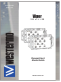
1
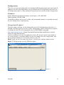
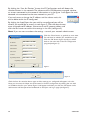
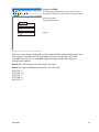
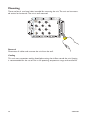
6641-2201
Viper
108 and 408
Managed 8-port
Ethernet Switch
www.westermo.com
© Westermo Teleindustri AB
User Guide
Legal information
The contents of this document are provided “as is”. Except as required by applicable
law, no warranties of any kind, either express or implied, including, but not limited to,
the implied warranties of merchantability and fitness for a particular purpose, are made
in relation to the accuracy and reliability or contents of this document. Westermo
reserves the right to revise this document or withdraw it at any time without prior
notice.
Under no circumstances shall Westermo be responsible for any loss of data or income
or any special, incidental, and consequential or indirect damages howsoever caused.
More information about Westermo can be found at the following Internet address:
http://www.westermo.com
2
6641-2201
Safety
!
Before installation:
Read this manual completely and gather all information on the unit. Make sure that
you understand it fully. Check that your application does not exceed the safe operating specifications for this unit.
This unit should only be installed by qualified personnel.
This unit should be built-in to an apparatus cabinet, or similar, where access is
restricted to service personnel only.
The power supply wiring must be sufficiently fused (e.g. Littlefuse 0461 1.25), and
if necessary it must be possible to disconnect manually from the power supply. If
fault contact is used, make sure that fault contact wiring is sufficiently fused.
This unit uses convection cooling. To avoid obstructing the airflow around the unit,
follow the spacing recommendations (see Cooling section).
!
Before mounting, using or removing this unit:
Prevent access to hazardous voltage by disconnecting the unit from power supply.
Warning! Do not open connected unit. Hazardous voltage may occur within this
unit when connected to power supply.
Care recommendations
Follow the care recommendations below to maintain full operation of unit and to fulfil
the warranty obligations.
This unit must not be operating with removed covers or lids.
Do not attempt to disassemble the unit. There are no user serviceable parts inside.
Do not drop, knock or shake the unit, rough handling above the specification may cause
damage to internal circuit boards.
Do not use harsh chemicals, cleaning solvents or strong detergents to clean the unit.
Do not paint the unit. Paint can clog the unit and prevent proper operation.
Do not expose the unit to any kind of liquids (rain, beverages, etc). The unit is not waterproof. Keep the unit within the specified humidity levels.
Do not use or store the unit in dusty, dirty areas, connectors as well as other mechanical
part may be damaged.
If the unit is not working properly, contact the place of purchase, nearest Westermo distributor office or Westermo Tech support.
Do not cover or bring mechanical force to the ventilation membrane on the back of the
unit.
Maintenance
No maintenance is required, as long as the unit is used as intended within the specified
conditions.
6641-2201
3
Agency approvals and standards compliance
Type
EMC
Approval / Compliance
EN 61000-6-1, Immunity residential environments
EN 61000-6-2, Immunity industrial environments
EN 55024, Immunity IT equipment
EN 61000-6-3, Emission residential environments
EN 61000-6-4, Emission industrial environments
EN 50121-3-2, Railway applications - EMC: Rolling stock – Apparatus
FCC part 15 Class B
EN 50121-4, Railway signalling and telecommunications apparatus
IEC 62236-4, Railway signalling and telecommunications apparatus
E-Mark, Road Vehicles, E1 no: 10 R - 0472161
Safety
Note
EN 60950-1, IT equipment
1 _ Applicable only for 3641-6360
FCC Part 15.105 Notice:
4
This equipment has been tested and found to comply with the limits for a
Class B digital device, pursuant to Part 15 of the FCC Rules. These limits
are designed to provide reasonable protection against harmful interference
in a residential installation. This equipment generates, uses and can radiate
radio frequency energy and, if not installed and used in accordance with
the instructions, may cause harmful interference to radio communications.
However, there is no guarantee that interference will not occur in a particular installation. If this equipment does cause harmful interference to radio
or television reception, which can be determined by turning the equipment
off and on, the user is encouraged to try to correct the interference by
one or more of the following measures:
… Reorient or relocate the receiving antenna
… Increase the separation between the equipment and receiver
… Connect the equipment into an outlet on a circuit different from that to
which the receiver is connected
… Consult the dealer or an experienced radio/TV technician for help.
6641-2201
Declaration of Conformity
Westermo Teleindustri AB
Declaration of conformity
The manufacturer
Westermo Teleindustri AB
SE-640 40 Stora Sundby, Sweden
Herewith declares that the product(s)
Type of product
Unmanaged Ethernet switch
Managed Ethernet switch
Model
Viper-008
Viper-408
Viper-408 E-mark
Art no
3641-0340
3641-0360
3641-6360
is in conformity with the following EC directive(s).
No
Short name
2004/108/EC
2006/95/EC
2011/65/EU
Electromagnetic Compatibility (EMC)
Low Voltage (LVD)
Restriction of the use of certain hazardous substances in electrical and electronic
equipment (RoHS)
References of standards applied for this EC declaration of conformity.
No
Title
EN 55022
EN 55024
EN 61000-6-1
EN 61000-6-2
EN 61000-6-3
EN 61000-6-4
EN 50121-3-2
EN 50121-4
EN 60950-1
Issue
Information technology equipment - Radio disturbance characteristics - Limits
and methods of measurement
Information technology equipment - Immunity characteristics - Limits and
methods of measurement
Electromagnetic compatibility - Generic standards - Immunity for residential,
commercial and light-industrial environments
Electromagnetic compatibility - Generic standards - Immunity for industrial
environments
Electromagnetic compatibility – Emission for residential environments
Electromagnetic compatibility - Generic standards - Emission standard for
industrial environments
Railway applications – Electromagnetic compatibility – Rolling stock Apparatus
Railway applications – Electromagnetic compatibility – Emission and immunity
of the signaling and telecommunications apparatus
Information technology equipment – Safety – General requirements
The last two digits of the year in which the CE marking was affixed:
2006
+A1:2007
1998
+A1:2001
+A2:2003
2007
2005
2007
2007
2006
2006
2006
14
Pierre Öberg
Technical Manager
12th Mars 2014
Postadress/Postal address
Tel.
Telefax
Postgiro
Bankgiro
Org.nr/
Corp. identity number
Registered office
S-640 40 Stora Sundby
Sweden
016-428000
Int+46 16428000
016-428001
Int+46 16428001
52 72 79-4
5671-5550
556361-2604
Eskilstuna
6641-2201
5
Type tests and environmental conditions
Phenomena
ESD
Test
EN 61000-4-2
RF field AM modulated
IEC 61000-4-3
Fast transient
EN 61000-4-4
Surge
EN 61000-4-5
RF conducted
EN 61000-4-6
Description
Enclosure contact
Enclosure air
Enclosure
Ethernet ports
Power port
Earth port
Fault port
Ethernet ports
Power port
Ethernet ports
Power port
Power frequency magnetic
field
Pulse magnetic field
Voltage dips and interruption
EN 61000-4-8
Enclosure
EN 61000-4-9
EN 50155
Enclosure
DC power ports
Radiated emission
Enclosure
Conducted emission
EN 55022
FCC part 15
EN 55022
Dielectric strength
FCC part 15
EN 50155
Temperature
Humidity
Altitude
Reliability prediction (MTBF)
Service life
Vibration, random simulated
long life
Vibration, random functional
6
MIL-HDBK- 217F
IEC 60068-2-64,
Cat. 1 class B
(EN 61373)
IEC 60068-2-64,
Cat. 1 class B
(EN 61373)
DC power port &
Ethernet ports
DC power port
Ethernet ports to other
isolated ports
Power & Fault port to
other isolated ports
Operating
Storage & Transport
Operating
Storage & Transport
Operating
Operating
Operating
Not Operating
Operating
Test levels
± 6 kV (crit A)
± 8 kV (crit A)
20 V/m 80% AM (1 kHz),
80 – 2500 MHz (crit A)
± 2 kV (crit A)
± 2 kV (crit A)
± 2 kV (crit A)
± 2 kV line to earth (crit A)
± 2 kV line to earth (crit A)
± 2 kV line to earth, ± 2 kV line to line
(crit A)
10 V 80% AM (1 kHz), 0.15 – 80 MHz
(crit A)
10 V 80% AM (1 kHz), 0.15 – 80 MHz
(crit A)
1000 A/m 50 Hz
300 A/m 16.7 Hz, 60 Hz, DC (crit A)
300 A/m (crit A)
10 ms interruption, 100 ms ±40% voltage
variation
Class B
Class B
Class B
Class B
707 VDC 1 min
2121 VDC 1 min
–40 to +70ºC
–40 to +70ºC
5 to 95% relative humidity
5 to 95% relative humidity
2000 m / 70 kPa
Ground Benign:
103 years @ 20ºC
100 years @ 40ºC
90 years @ 60ºC
Ground Mobile:
5.92 years @ 20ºC
5.91 years @ 40ºC
5.88 years @ 60ºC
10 year
Vertical:
7.9 m/s2
Transverse: 7.9 m/s2
Longitudinal: 7.9 m/s2
3x5h
Vertical:
1.0 m/s2
Transverse: 1.0 m/s2
Longitudinal: 1.0 m/s2
3 x 10 min
6641-2201
Phenomena
Shock, half sine pulses
Test
IEC 60068-2-27,
Cat. 1 class B
(EN 61373)
Description
Operating
Test levels
Shock, sawtooth
IEC 60068-2-27,
Cat. 1 class B
(IEEE1478-2001)
Operating
Vertical:
100 m/s2
Transverse: 100 m/s2
Longitudinal: 100 m/s2
11 ms, 3 x 6 shocks
Enclosure
Dimension W x H x D
Weight
Degree of protection
UL 94
Nickel coated zinc
IEC 529
Enclosure
Flammability class V-1
175 x 100 x 50 mm
0.8 kg
IP 65 when all ports are protected/
connected else IP 40
Convection
Wall mounted
Cooling
Mounting
6641-2201
Vertical:
50 m/s2
Transverse:
50 m/s2
Longitudinal:
50 m/s2
30 ms, 3 x 6 shocks
7
Description
Functional description
Viper is a range of switches consisting of two different function levels developed for
rail and industrial applications. To meet the environmental requirements from rail and
harsh industrial applications the switch has rugged M12 Ethernet connectors and full
metal housing. The switch fullfill IP 65 degree of protection when all ports are protected/
connected else IP 40. Our unique FRNT (Fast Recovery of Network Topology) technology is the fastest protocol on the market to re-configure a network in the event of any
failure of a link or hardware. Real-time properties are implemented in the Viper108 and
408 in order to achieve determinism for real time critical applications. The Viper-switches
supports QoS (Quality of Service) with four priority queues and strict priority scheduling
as well as HoL (Head of Line Blocking Prevention). All to assure that the data network is
deterministic.
8
6641-2201
Interface specifications
Power and fault relay port PWR
Rated voltage
24 to 110 VDC
Operating voltage
24 to 110 VDC ±40%
Rated current
Rated frequency
40 mA @ 110 VDC
140 mA @ 24 VDC
DC
Inrush current, I2t
Max 0.02 A2s @ 24 – 110 VDC
Startup current *
7 Apeak @ 24 – 110 VDC
Polarity
Reverse polarity protected
Redundant power input
No
Isolation to
Connections X1 – X8 and to ground, 1500 VAC.
Fault relay belongs to the same isolation group as the power
supply lines (fault relay signals are also contained within
PWR).
4 pin male M12 connector with A-code
Connection
Shielded cable
M12, recommended cable area 0.5 mm2 recommended
(minimum 0.25 mm2), cable dimensions depend on choice of
M12 connector
Not required, twisted pair is recommended
Fault relay resistance
< 10 Ω
Operating voltage
Up to 110 VDC
Max continuous current
250 mA
Connector size
* If external power supply is used it must meet specified startup current.
M12 A-Coded
Power
Connector
6641-2201
Position
Direction
Description
1
U+
Positive supply voltage
2
Out
Alarm relay (status) +
3
0V
Negative supply voltage
4
Out
Alarm relay (status) –
Housing
Shield
Chassis of product (ground)
9
Fault Contact
The Viper switch is equipped with a potential free normally closed fault contact.
The fault contact is a solid state component (relay) that requires power to work and it
is transient protected. Additionally, the fault contact is opened when any of the following
conditions is met:
• No voltage on the power supply pin, a voltage level outside the legal voltage range
or current limitation on the voltage source is applied on the power input.
• Link alarm i.e. missing link on any Ethernet port that has link alarm enabled.
• Redundancy Mode activated i.e. one or more FRNT link is down.
Description of how connection to the fault contact could be done is shown below.
The relay is closed when the unit is OK and open at failure. The relay is of semiconductor type (no moving parts). It is specified for max current 250 mA continuous,
500 mA peak (10 ms), operational voltage up to 110 V, protected by a 150 VDC-varistor,
ON-resistance less than 10 Ohm, and leakage current max 1 µA.
External relay
To logic input
+24/48 VDC
Viper
2
Viper
+
1 kΩ
2
Input on PLC
4
4
0V
Service port
The Service Port should not be used by non other than the Westermo Technical Support
team. Do not connect any device or cable to the Service Port.
10
6641-2201
Ethernet TX port X1 to X8
Electrical specification
IEEE std 802.3. 2000 Edition
Data rate
10 Mbit/s or 100 Mbit/s, manual or auto
Duplex
Full or half, manual or auto
Circuit type
TNV-1
Transmission range
150 m
Isolation to
Galvanic connection to
Other Ethernet ports, 500 VAC
PWR, 1500 VAC
None, except for shielded contact to housing
Connection
4-pole M12 female with D-code
Shielded cable
Not required, twisted pair is recommended
Conductive housing
Nickel plated zinc, metal housings of X1-X8 also connected
to the housing
8 Ethernet (X1-X8)
Number of ports
6641-2201
Position
1
Direction
Out
Description
Transmit Data +
2
In
Receive Data +
3
Out
Transmit Data –
4
In
Receive Data –
Housing
Shield
Chassis of product (ground)
11
Location of Interface ports, LED's
LED indicators
LED
Status
Description
PWR
GREEN
Unit indicates no fault
RED
Unit indicated fault
FLASH
Connected to IP Configuration tool
OFF
FRNT is not enabled or not supported
GREEN
RED
FRNT is running and the switch is configured
as member switch in the ring.
FRNT is running and the switch is configured
as Focal Point
FRNT Error
ST1
GREEN
Indicates STP root
ST2
NC
X1 to X8
OFF
No Link
GREEN
Link is up
GREEN
FLASH
YELLOW
ON
Data is transmitted
FRNT
GREEN
FLASH
Port larm and no link. If RSTP/FRNT mode
are activated, port is blocked.
X5
X1
FRNT
X2
SERVICE
X3
X6
X7
ST1
ST2
PWR
12
X4
X8
6641-2201
Configuration
The units can easily be configured via the onboard Web based configuration tool. Local IP
addresses can also be configured by using the Westermo IP Configuration tool, from the
IP Configuration tool it is then possible to browse into the unit for further configuration.
IP Address
When delivered, the default IP address of the Viper is 192.168.2.200.
Default gateway 192.168.2.200
If the default address of the unit is valid in the connected network it is possible to access
the unit directly from a web browser.
Change local IP address
The local address of Viper can be configured using the IP Configuration tool, then it is
possible to browse into the unit for further configuration. The IP Configuration program
is available on the CD or for download from the WESTERMO web page:
http://www.westermo.com, choose Downloads/Software/Ethernet/Ethernet switches
Name: IP config Westermo.zip
Install the software and start the application from a PC on the network connected to
the same network as the Viper. Make sure that the Default IP of the configuration software (see figure below) is in the same subnet as your PC.
Note! If you are not sure about the subnet – consult your network administrator.
Note! IP Config version must be 10.0.0 or higher.
IP configuration
Default IP: 192. 168. 2. 200
Device list:
IP Adress
192.168.2.200
Subnet Mask
255.255.255.0
Scan for Devices
6641-2201
MAC Adress
00-07-7C-80-4A-6C
SW Ver
3.15
Mask: 255. 255. 255.
Type
Viper 108
0
Help
About
Status
Close
Figure 1
13
By clicking the “Scan for Devices” button the IP Configuration tool will detect the
switches/routers in the network. The software will list all Westermo managed switches
or routers connected to the network. Information as in the figure 1 will appear for each
detected unit connected to the same network as your PC.
IP configuration
If you only want to change the IP address and the subnet mask, this
can be done within the IP config tool.
By clicking the listed Viper that you wish be re-configured you will be
Figure 2
asked if you would like to access via web figure 2. Click the abort button,
enter the preferred IP address, Subnet mask and IP gateway address and
click the Set button to confirm the settings in the unit (see figure 3).
Note! If you are not sure about the settings – consult your network administrator.
Access switch via web?
OK
Click the Close button to get back to main view.
You will then be asked if you would like to quit.
Click the OK button, figure 4, and you will be
back to the main view of the IP Configuration
program(see figure 1).
Selected Device
Viper configuration
IP adress:
192
168
2
200
Subnet mask:
255
255
255
0
MAC adress:
00 07
Host name:
Westermo
Location:
location
IP gateway adress:
192
Cancel
7C 80 4A 6C
168
2
200
IP gateway adress:
Set
Close
Figure 3
IP configuration
You have set new parameters on the switch. The switch must be restarted in order for the new parameters to take effect (except IP address change). Type cancel to return to
selected dialog or OK if you still want to quit.
OK
Cancel
Figure 4
Click the Scan for switches button again and the settings you configured will appear in the list.
Now you can access the Viper via the browser for further configuration by clicking the unit with
an IP address that fits your subnet. Figure 2 will appear and when you click the OK button and a
web browser will be opened and redirected to the Viper unit log in page (see figure 5).
14
6641-2201
Westermo - location - Provided by Westermo UK
http://192.168.2.200/conf/p.cgi
File
Edit
View
Favorites
Tools
Westermo - location
Help
Log in via Web
Google
You will be prompted with a Login screen where
the default settings for Username and Password are:
Home
Feeds (J)
Print
Page
Tools
Username: admin
Password: westermo
Login
Username:
Password:
Login
Figure 5
Done
Internet
The unit can be easily configured via the on-board Web based configuration tool.
The network interface and switch properties can be configured and stored.
The Web tool also has an extended integrated help function describing all
configuration options.
Note! Max 10 characters can be used in the login.
Note! For login the following characters are not valid.
ASCII 34 = "
ASCII 35 = #
ASCII 39 = ’’
ASCII 40 = (
ASCII 92 = \
6641-2201
15
Mounting
There are four 6 mm bore holes intended for mounting the unit. The unit can be mounted vertical or horizontal. The unit is wall mounted.
X5
X1
FRNT
X2
SERVICE
X6
X7
X3
ST1
ST2
PWR
X4
X8
Removal
Disconnect all cables and unscrew the unit from the wall.
Cooling
This unit uses convection cooling. Avoid obstructing the airflow around the unit. Spacing
is recommended for the use of unit in full operating temperature range and service life.
16
6641-2201
Factory Reset
The factory reset option restores the switch to its original factory condition.
The switch will be restored using the following settings.
• IP address 192.168.2.200
• Subnet mask 255.255.255.0
• Gateway 192.168.2.1
• All Ethernet ports are enabled and set to Auto Negotiate
• All applications are disabled
• Password reset to westermo
To perform a Factory Reset follow the procedure below. Read all steps before
starting. If you have any doubts whether the reset is performed or not, do
NOT unplug the power supply, wait for confirmation according to step 5.
1. Disconnect the power
2. Connect cables between port x1-x6 and port x2-x5.
3. Apply power
4. Wait for approx imately 90 seconds. (Some LED will flash during start up
5. When the Green LED's on all Ethernet ports are constantly on, then remove the
cables connected to port x1-x6 and x2-x5.
6. It is now safe to remove the power and restart the switch.
7. When the switch has started up it will have the default settings.
NOTE! If the power is removed before the factory reset has finished,
the switch may be come unusable.
6641-2201
17
Dimensions
Measurements are stated in millimeters.
175 ±1
164 ±1
142 ±1
53,4 ±1
41,5 ±1
22,7 ±1
22 ±1
3,9 ±0,3
56 ±1
100 ±1
M5
Max 7,5
Min 4,0
6,5 ±0,2(4x)
55,6
37,2
28
18,8
0,4
18
82
97,5
51
66,5
35,5
4
0
0
6641-2201
Westermo • SE-640 40 Stora Sundby, Sweden
Tel +46 16 42 80 00 Fax +46 16 42 80 01
E-mail: [email protected]
www.westermo.com
United Kingdom
Westermo Data Communications
Talisman Business Centre
Duncan Road, Park Gate, Southampton. SO31 7GA
Tel: +44 (0) 1489 580 585 • Fax: +44 (0) 1489 580 586
[email protected] • www.westermo.co.uk
Germany
Westermo Data Communications
Goethe Strasse 67
DE-68753 Waghäusel
Tel: +49 (0) 7254 95400-0 • Fax: +49 (0) 7254-95400-9
[email protected] • www.westermo.de
Austria
Westermo Data Communications
Tel: +43 (0) 72030 3920 • Fax: +43 (0) 2235 86131
[email protected] • www.westermo.at
France
Westermo Data Communications
Bat. A, 9 Chemin de Chilly
FR-91160 Champlan
Tel: +33 1 69 10 21 00 • Fax: +33 1 69 10 21 01
[email protected] • www.westermo.fr
North America
Westermo Data Communications
939 N. Plum Grove Road, Suite F,
IL 60173 Schaumburg, USA
Tel: +1 847 619 6068 • Fax: +1 847 619 66 74
[email protected] • www.westermo.com
Singapore
Westermo Data Communications
84 Genting Lane #07-03
Cityneon Design Centre
Singapore 349584
Tel: +65 6743 9801 • Fax: +65 6745 0670
[email protected] • www.westermo.com
Malaysia
Westermo Data Communications
84 Genting Lane #07-03,
Cityneon Design Centre,
Singapore 349584
Tel : +6 012 2781156 • Fax : +603 8062 7467
[email protected] • www.westermo.com.sg
China
Westermo Data Communications
2F Building B
No.1618 Yishan Road
Shanghai 201103
Tel: +86 21 6145 0400 • Fax: +86 21 6145 0499
[email protected] • www.cn.westermo.com
Westermo Teleindustri AB have distributors in several countries, contact us for further information.
REV.F 6641-2201 2012-09 Westermo Teleindustri AB, Sweden – A Beijer Electronics Group Company
Sales Units
Sweden
Westermo Data Communications
Svalgången 1, Vallbyinstitutet, 724 81 Västerås
Tel: +46 (0) 21 548 08 00 • Fax: (0) 21 35 18 50
[email protected] • www.westermo.se