1
S ARS
OWNER'S
MANUAL
Model No.
390.291198
390.291358
390.291558
390.291658
390.291698
390.291758
CAUTION:
Read and Follow
All Safely Rulesand
Operating Instructions
Before First Use of
ThisProduct.
Save ThisManual For
Future Reference.
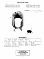
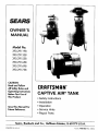
CRRFTSMRN°
CAPTIVE AIR ®TANK
• Safety Instructions
• Installation
• Operation
• Service Hints
• Repair Parts
Sears, Roebuck and Co., Hoffman Estates, IL 60179
PRINTED
IN
USA
U.S.A.
Form No
F642-9821 (Rev 7/29/04)
READ AND
FOLLOW
SAFETY
INSTRUCTIONS!
This is tile safety
alert symbol
When yon sec this symbol on your tank or ill this nlantlal, look for one nf the fol-
A
h)wing signal words
personal injur_ :
and he alert
to
the
|_)r
potential
DANGER \V;ll'l/_,
ah()(l[
haz;ll'dS thai will cause seriotls pe]'sonal injury, death or major property
damage
if ignored
WARNING
[ AWARNING
warns
serious personal
ignnr('d.
]
CAUTION
minor
CAUTION
I
about
injury,
warns
personal
about
injury
hazards
that
death or major
hazards
or Call
will
prnperty
that will
or pn)pert T damage
or can
cause
if ignored.
The label NOTICE indicates
special instructions
important
but not related to hazards.
Carefully
read and follow
this manual
and on tank.
cause
danulge if
all safety
wlaich
instructions
are
in
Keep safety labels m good condition.
Replace missing or damaged
RULES
FOR SAFE INSTALLATION
AND
sal_ty labels.
OPERATION
1. Read these Rules and the Instructions carefully. Failure
to follow them could cause serious bodily injury and/or
property damage.
NOTICE: Ahhongh No. 2729 Relief Valve is set to open at
75 PSI, lot your safety Captive Air _Tanks are designed and
rated to operate at up to 100 PSI.
AWARNING] These water storage tanks arc designed for
Hazardous
operation on cold well water systems limpressure
ited to a maximum working pressnre of 100
pounds per square inch (PSI). If your water system can exceed 100 P.S.I., install a Sears No. 2729 relief valve on the
system. Failure to follow these instructions can canse tank
blow-up and result in serious injury.
2. Be sure installation meets all local plumbing,
electrical and well codes.
WIZ_NOT
_FJVSE FROM
i_e
,_y
S_t_do
BE LIABLE
PROPERTY
not
4. Before installing or servicing your
pump power source is disconnected.
FOR £OSS OR DAMAGE
DAMAGE
O_
DIRECTLY
the eXClusiOnlof
limitation
OF
LIAB_
TO PROPERTY
OR IND1RECTL
of incidental
OR ANY
pump,
BE SURE
....
INCIDENTAL
OR CONSEQUENTIAL
LOSS OR EX.
y FROM THE USE OF THZS PRODUCE
or consequential
damages,
so the above
limitation
or exclusion
not app_ to you_
_x_i_'SERVIGE
UNITED ST)I'TES.
_s
alo_
3. Always test water from well for purity before using. Call
your local health department for testing procedure.
LIMITATION
.....
__
pnmp,
warranty
THE NEAREST
SEARS SERVICE CENTER/DFaPARTMEIVT
YOUR LOCAL SEARS SERVICE CENTER OR STORE.
IS AVAILABLE
BY SIMPLY CONTACTING
FOR SERVICE OUTSIDE THE {LS.A., CONTACT
gives you specific
legal rights,
Sears, Roebuck
and you may also have other
and Co., Dept.
817 WA,
2
tights
which
Hoffman
vary from state
Estates,
IL 60179
to state.
IN TI_
CONTENTS
WARRAN'I_'
INTRODUCTION
...................................................
2
SAFETY ............................................................................
2
INSTAI+I+ATION...........................................................
3-6
Please read our instructions before yon install and use your
tank. This will help you obtain full benefits ti'om this tank.
It will also help you avoid needless service expense that
resuh
our
()IWRATION ....................................................................
we
cannot
control
cannot
cover
in
lfl-l 1
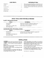
BASIC TOOLS
AND MATERIALS
NEEDED
INSTALLATIONS
TOOLS
MATERIALS
Pipe Wrenches
Plastic Pipe and Fittings (as required
Screwdriver
Teflon Tape (DO NOT use pipe joint compound
Knife or Saw to Cut Plastic Pipe
Tire Pressure
GALVANIZED
aild
7-9
REPAIR PARTS ...........................................................
PIPE
catlses
7
SERVI('E HINTS ............................................................
PLASTIC
from
\¥a rrailt y+
to complete
job).
on
plastic fittings) or Plasto-Joint Stik*
Gauge
STEEL PIPE INSTALLATIONS
TOOLS
HATERIALS
Pipe Wrenches
Screwdrivers
Galvanized
Pipe Joint Compound
Pipe Cutting and Threading
Tire Pressure
Pipe and Fittings (as required
to complete
job).
or Teflon tape
Tools
Gauge
INSTALLATION
+_WARNINt If your system can develop more than 100
Hazardous
PSI pressure, install a Sears No. 2729 relief
pressure
valve in system to prevent possibility of
tank blow-up.
Standard pipe fittings, such as nipples, tees and elbows
must be purchased locally. If you are using a horizontal jet
pump mounted on top of tank, Figures 5 and 6, Kit No.
2788 is required. See Page 10 for contents of kit.
NOTICE:
DO NOT use any type
water on Hose to Plastic fittings.
of lubricant
than
If your present system has an air volume control (AVC), remove it and plug AVC port on pump.
ff rigid piping is installed
to support
the piping.
on inlet flange,
BE SURE
Complete
pump,
tank, and piping system MUST be protected against below freezing
temperature.
Failure to do
so could cause severe damage
and voids the warranty.
to elbow
other
For proper installation of your pump to tank, follow one
of the typical installations on Page 4 and 5. Use Teflon tape
on all threaded connections
to tank.
* Lake Chemical
Co., Chicago,
Illinois.
Priming
Priming Plug,
Priming Tee
(User Supplied}
Priming
..
(User
Plug,
Tee
Supplied)
To Service
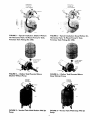
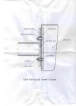
FIGURE
I - Typical Installation: Shallow Well Jet
On Horizontal Tank. To Mount Pump To Tank,
FIGURE 2 - Typical Installation: Deep Well Jet On
Horizontal Tank. To Mount Pump To Tank,
Purchase Tank Fittings Kit 2788.
Purchase Tank Fittings Kit 2788.
1" x 3/4" Reducer
Supplied)
Supplied}
From
Fgom
Well
Wel_
To SerVice
To Se_ic(
FIGURE 3 - 2 Gallon Tank Mounted
Shallow Well Jet Pump
FIGURE
Above
4 - 2 Gallon Tank Mounted
Above
Deep Well Jet Pump
pnming
pnrning
priming Plug,
pNmingTee
(UserSupplied)
.
Plug,
T6_
(U ser Supolied)
To Service
FrOm
Well
FIGURE
5 - Vertical
Tank With
FIGURE
Shallow Well Jet
Pump
Pump
4
6 - Vertical
Tank With
Deep Well Jet
INSTALLATION
50 and 85 gallon tanks are
not equipped with mntmting bracket.
Install pump beside tank as sbo\vn
NOTICE: When using plastic fitting or
installing a plastic pump, use only
Teflon tape or Plasto-Joint Stik on male
threads.
1"-
1" x 1" Tee
2* - 1" Nipple
3* - 1-1/4" X 1" Reducer
Required
for 50 and 85
gallon
tanks.
Bushing
*Not furnished
- must be
purchased
locally
"_""
Pressure
Pump To Tank FiRings
Package
Not Furnished
With Tank,
Purchase
Kit Stock No. 2788
From Your Sears Store.
Regulator
1" Disohar(
!
2358b 0697
FIGURE
6 - 19, 36, 50 and 85 Gallon Tanks With
Multi-Stage
Pumps
TANK
Electrical
Disconnect
Switch (All _"_Installations)
SIZES
19 GALLON
36 GALLON
50 GALLON**
Control Center
(3-Wire Pump
Only)
_-_,
85 GALLON**
I
LAWARNING
j] High capacity pumps
should be used with the 50 or 85
gallon tank only.
Cable for Two-Wire
Pum
from Pressure
Switch to Motor
** 1-1/4" to 1" reducer
for 1" piping.
To Pump
Motor
Y
Stock No. 2722
FIGURE
7-
Tanks With
High Capacity
Relief Valve,
Sears Stock
No. 2729
Or Residential
5
Size Submersible
required
Relief Valve (No. 2729)
must be purchased
.Pressure Gauge,
Sears Stock
No. 2768
Submersible Purr
Manifold, Sears
Note:
Guardsearsll
Stock
No.
2721
From Well
Not
to
2391 0496A
Pressure Switch,
Sears Stock No.
2782 or
"-k
[ NOTIOE:
Installthan
relief I
valve
nottank.
more
24"
from
Scs_e
-
Pumps
separately.
I NSTALLATION
If your system
can develop
more
than
100 PSI pressure,
install
a Sears
No.
2729 relieve
valve in system
to prevent
possibility
of tank blow Ul).
_kWARNIN(
Hazardous
pressure
(_apdve Air Tanks can be connected
together to increase
the SUl'q'_l} of usable water (dntv_'down).
Two tanks of the
same size \\ill double the suppl 3 and three tanks will triple
thc SUl_p[ } See Figtlres 8 and _) l_)r t} pleat illstallaliolaS
NOTICE: All (;apfixe Air "lhnks except Models 391) 291 I_;N
and 390.291358
are designed to operate ill tile vertical
pusititm.
\\ hell tlSJl)_ a _,tiblliersiblc
ptinlp, the iI]allil_>ld and sxvilch
assembly must lye installed in the pipe lille as close to tile
center of the tanks as possible.
See Figures 8 and 9.
The tank is shipped from tile l_tctury with a pre charge nf
air. This system DOES NO'I' require the use of an 3' outside
air charging devices such as ;tit- volume controls on jet
pumps, or bleeder orifices on suhmersible puml)s.
Tanks
Tanks
From
Well
To
Service
Froml
Well
To
Service
/
Pressure Switch and 27229
Relief Valve Location When
Pressure Switch and 27229
Using Submersible
Using Submersible
FIGURE
Relief Valve Location When
Pump
8
FIGURE
Pump
9
OPERATION
BEFORE
Your tank
YOU
START
is facto W charged
YOUR
with
PUMP
forty (40)
pounds
of air
NOTICE:
For years of trouble
free service,
check
precharge annually. See service hints (Page 7) for procedure.
pressure.
To determine
pressure
switch setting, see pump
owner's
manual.
If your pump pressure
switch
cut-in setting is less than forty (40) pounds,
the tank air pressure
MUST be reduced
to this cut-in pressure
switch
setting
(see table). To do this, bleed air from the valve located on
NOTICE:
top of the tank. Check pressure
frequently
with an accurate tire pressure
gauge until correct
pressure
has been
reached.
Conventional
pump
pressure
pumps are as follows:
CUT IN/CUT
OFF
switch
settings
on
PSI
20 PSI
30/50
PSI
30 PSI
40/60
PSI
40 PSI
and
expel
all air out of the
pump to run until there is a steady
()pen and close faucets repeatedly
has been removed.
SEARS
PRECHARGE
20/40
Release
piping
sys-
tem and the water reservoir
portion
of the Captive Air®
Tank. This is required
on new installations,
pumps requiring repriming
and pumps that have been apart for service.
To accomplish
this, open faucets farthest
away from tank
and start the pump.
Observe
the sputtering
water flow
from faucets.
This is a mixture
of air and water. Allow
air free stream of water.
until you are sure all air
If air continues to remain in system, check for leaks in piping on suction side of pump system (Jet Pumps Only).
If yuu have a submersible pump, remove the bleeder orifices in the pipe (just below the well seal) and replace
bleeder orifice with pipe plugs.
6
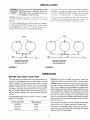
OPERATION
A
B
Tank is nearly empty:
Water storage bag is at bottom. Air expands to fill space
above bag. The pump starts
FIGURE
Water starts to fill the bag:
As bag fills, air above the
bag is compressed,
D
Bag is full to capacity:
Air is compressed to the
utmost for maximum drawdown. The pump stops
Water is being drawn
from the bag:
Compressed air in the
tank forces water out.
10
SERVICE
NOTICE: To prevent
annually.
TO CHECK
TANK
waterlogging,
check tank air charge
HINTS
TO CHECK
PUMP
PRESSURE
SWITCH
1. Start the pump and allow the pressure
off.
AIR CHARGE
If dmwdown (amount of water that comes out of tank per
pump cycle) decreases significantl}; check as follows:
1. Check
pump,
C
air charge in tank. Shut off electric power
open faucet near tank, and drain completely.
to
2. At the air valve in top of tank, check air pressure with
standard tire pressure gauge. Air pressure should bc the
same as pump pressure switch cut-in setting.
3. If the air pressure is below the cut-in setting, add air to
the tank. Use an air compressor or a portable air storage
tank.
switch to shut it
2. Check the tank air pressure with the tire gauge. It should
be the same as the cut-off pressure tbr your system. (See
"OPERATION" section on Page 6 for correct pressures).
3. If the pressure reading is different from your system recommended pressure, the switch should be replaced.
REPLACEMENT
OF AIR VALVE
If air valve hecomes broken, or leaks beyond repair, it may
be necessary to replace it.
4. Use soap or liquid detergent
to check for air leaks
around air valve. Continuous bubbling indicates a leak.
If necessary, install new core in air valve. This is the same
as those used for automobile tubeless tires.
Groove
1449 0195
Remove nuts
J ( 6 Places)
FIGURE
12
It is a standard tubeless tire valve which snaps in position
in groove as it is pulled up thru hole from inside tank.
1. Disconnect
power to pump.
2. Relieve (drain) ALL water
closest to tank.
in system by opening
faucet
14480195
3. Relieve (expel) ALL air pressure
core from inside of valve.
FIGURE
II
4. Disconnect
in tank by removing
outside piping only to tank.
SERVICE
5. With sharp knife, cut off stem as close to tank
sible. Push remaining
portion
into tank.
as pos-
TESTING
FOR
1. l)iscnnnect
6. Lay tank on side and remove six (6) nuts from studs. Tap
cover to break seal add remove
cover assetnl_ly Iroln
tallk. You cat1 flow set tilt: villyl bag. Scc Figure I I
LEAKAGE
OF VINYL
BAG
pnwcr tu pump.
2. Relieve (drain) ALl. water in system by opening
closest
lancet
1o tatlk
3. Relieve (expel) AH air pressure
core l]'om inside of air valve.
7. Before removing vinyl bag from grnove scat in tank. BF.
SURE all water is drained fi'om bag This can be ac
complished
by tipping tank upright anti allowing remaining water to drain.
8. Carefully remove lip portion
and push bag into tank.
HINTS
4. Disconnect
in tank by removing
outside piping nnly to tank.
5. Turn tank upside down.
of bag from grnove seat
NOTICE: BE CAREFUL not to damage air valve when
tipping tank. Remnval of air valve is not required. If
water leaks nut of the wtlve core opening, the vinyl bag
has a hole in it and nlust be replaced.
9. Block up tank as shown in Figure 13. This will allow
cut off portion of stem to slide down to bottom of tank.
Reach in around bag until you find it and remove it.
PROCEDURE
BAG
FOR
REPLACING
VINYL
Be sure all air has been expelled
before removing nuts.
FOR
6, 19 AND
36 GALLON
from tank
TANKS
1. Carefully lay tank nn its side.
sl!des to the bottom of tank
2. Remove nuts around cover plate.
to retrieve stem
FIGURE
3. Tap cover to break the seal and remove cover assembly
from tank. You can now see the vinyl bag.
4. Bag cannot be removed in one piece. Wherever convenient, grip bag with pliers and pull outward. At the
same time cut bag with sharp knife or single-edged
razor blade. Continue pulling and cutting until bag is
completely removed.
13
10. Wipe a thin film of soapy solution on top half of replacement stem and insert in stem hole in top of tank.
It is necessary to use a valve stem pulling tool to pull
stem thru opening. This toni is the same as used by
your local filling station and Sears Automotive Center
when servicing tubeless tires.
5. Clean and dry inside of tank.
NOTICE: Before replacement bag can be inserted
it must be tightly rolled up as follows:
1. Place bag on clean surface with opening
3. Tightly roll bag towards center
CAUTION
] It is important
that nuts be tightened
5. Finish rolling bag.
6. As an aid for inserting bag in tank, sprinkle outside with
talcum powder.
as
follows: First, hand tighten all nuts. Then tighten one
nut to a snug fit. Next, tighten the one opposite to a
snug fit. Proceed, tightening the others in opposite
pairs to a snug fit. Recheck all nuts in same opposite
patterns to be sure they are evenly tightened and you
have a good seal. DO NOT overtighten,
as you may
twist the studs off the tank. With a torque wrench,
tighten to 85 inch pounds.
14. Tip tank upright and assemble
15. Recharge
tank with proper
opening.
4. Before center opening is covered up, force air out of remalning portion of bag.
and place on
13. Hand tighten all nuts on studs.
[_
up.
2. Flatten bag and force air out.
11. Pull neck of bag out of tank opening and seat in groove.
BE SURE ring groove is clean.
12. Clean sealing surface of cover assembly
studs.
in tank,
7. With tank upside
tank.
down,
push tightly rolled bag into
8. Put your arm in bag and push sidewalls outward.
NOT important that all wrinkles be removed.
It is
9. Clean flange ring and groove of tank.
10. Pull lip of bag through
tank opening
and place in ring
groove.
11. MAKE SURE it seals properly
for operation.
12. Clean sealing surface
studs.
amount of air.
8
of cover
in groove.
assembly and place on
SERVICE
13. hlstall nuts and washers
(m studs, ltand tighten all nuts.
,&.CAUTION It is inlportam
that nuts he tightened as
fi)llows: First, hand tighten all mils. Then tighten one
rail Io a snug 1][ Next. tighten the one opposite to a
Siltlg I:il Proceed, tightening the _thcrs in opposite
pah-s lo a suug lit, Recheck ;ill ntltS in SalUe opposite
patterns
to lie sure
they arc i.-v,qlly
tightened and you
have a good seal. DO NOT overtighten,
as you may
twist the studs off the tank. With a torque wrench,
tighten to 85 inch pounds.
14. Tip tank upright and reassemble
15. Recharge
FOR
tank with proper
SO AND
_,WARNINq
Hazardous
pressure
R_r openltion.
amount of air.
85 GALLON
TANKS
Be sure all air has been expelled
before removing nuts.
from tank
1. Carefully lay tank on its side.
2. Remove nuts around cover plate.
3. Tap cover to break the seal and remove cover assembly
from tank. You can now see the vinyl bag.
4. Bag cannot be removed in one piece. Wherever convenient, grip bag with pliers and pull outward. At the
same time cut bag with sharp knife or single-edged
razor blade. Continue pulling and cutting until bag is
completely removed.
5. Clean and dry inside of tank.
6. Place hag on its side on dry clean surface.
7. Flatten bag and force air out.
8. Starting on one side, tightly roll bag to other side.
NOTICE: Before opening
maining air out.
is rolled
closed,
force re-
9. Finish rolling bag.
10. As a aid for inserting bag in tank, sprinkle
talcum powder.
outside with
11. With tank on its side, push tightly rolled bag into tank
opening.
NOTICE: Push bag in tank only the length of the roiled
bag.
12. Insert arm in bag and push sidewalls outward.
important that all wrinkles be removed.
It is NOT
13. Clean flange ring and groove to tank.
NOTICE:
steps:
Two people
are required
for the following
14. Holding the bag, stand tank open end up.
NOTICE: DO NOT damage air valve. It may be of help
to lean tank in corner.
15. Pull lip ring of bag through
ring groove.
tank opening
and place in
HINTS
16. MAKE SURE it seats pruperly
17. (]lean
studs.
sealing
surface
of cover
IN hlstallllulSal/d\vashcrsolaStUdS
in groove.
assembly
and
place
oil
Ilatldliglltcn;illlltllS
NOTICE: It is hnportaut
that mils bc tightened
:is lol
lows; First, hand tighten all uuts. Tllen tighlc, il uric nut
to a suug fit. Next, tighten the one opposite
to a Slltlg
fit. Proceed,
tightening
the others in opposite
pairs to
a snug fit. Recheck
all nuts in same opposite
patterns
to be sure they arc evenly tightened
and you have a
good seal. DO NOT overtightcn,
as you may twist the
studs off the tank. With a torque wrench,
tighten to 85
inch pounds.
19. Tip tank upright and reassemble for opcmtiun.
20. Recharge tank with proper amount of air.
PUMP
TO TANK
FITTINGS
Pump to tank fittings Package No. 2788 is not furnished.
You may purchase
it at your local Sears Store.
PACKAGE
Required
low/deep
NO. 2788
to install all SEARS Captive
well jet pump.
REPAIR
KEY
NO.
O--6
Air' Tanks
with
PARTS
PART
NO.
PART
DESCRIPTION
1
U78-777PA
2
3
U78-770P
U74-37J
Adapter * 1" NPT (Male) by 1" Insert (2 Req.)
Elbow - 3/4" NPT (Male) by 1" Insert
Hose
4
U19-55SS
Clamp - Hose (2 Req.)
5
U30-701ZP
Bolt - 3/8" - 16 x 1-3/4" Lg. (2 Req.)
6
U43-62ZP
Flat Washer - 3/8" (2 Req.)
7
U43-12ZP
Lock Washer - 3/8" (2 Req.)
8
U36-38ZP
Nut - Hex 3/8" - 16 (2 Req.)
9
U78-769P
Elbow - 1" NPT (Male) by 1" Insert (2 Req.)
CAPTIVE
(6 GALLON)
(19 GALLON)
shal-
AIR ®TANK
MODEL
MODEL
390.291198
390.291358
REPAIR PARTS
KEY
NO.
1
MODEL
390.291198
PART NO.
MODEL
390.291358
PART NO.
U20-7
U20-13
U31-442P
1A
2
U36-202BTI"
3
3
PART
DESCRIPTION
Bag - Vinyl
Inlet Flange
U31-446P
Inlet Flange
U36-202BTt
U78-777PA
Nut 5/16 - 18 Hex (6 Req.)
U78-77OP
1
/
Adapter 1" NPT Male
Elbow - 3/4" NPT
/
(Male) by 1" Insert
U212-160t
U212-160t
Air Valve w/Cap
• Not Illustrated.
t Standard hardware item, may be purchased locally.
1o
2
CAPTIVE
AIR ®TANK
MODEL
390.291558
(I 9 GALLON)
MODEL
390.291698
(50 GALLON)
MODEL
390.291658
(36 GALLON)
MODEL
390.291758
(85 GALLON)
NOTICE:
50 and 85 gallon
tanks
are not equipped
with mounting
bracket.
Install pump beside tank
as shown
on Page 5.
REPAIR
Key
No.
PARTS
390.291558
19 Gallon
Tank
390.291658
36 Gallon
Tank
390.291698
50 Gallon
Tank
390.291758
85 Gallon
Tank
Part
Description
1
U20-8
U20-9
U20-10
U20-14
Bag - Vinyl
2
U31-446P
U31-446P
U31-447P
U31-447P
Inlet Flange
3
U36-202BT t
U36-202BTT
U36-202BTf
U36-202BTt
Nut - 5/16 - 18 Hex. (6 Req.)
4
U212-160t
U212-160t
U212-160t
U212-160t
Air Valve w/cap
tStandard
hardware item, may be purchased locally.
Toorderparts,call:
Sears Produ_ Service
I 800 366_7278
11
SE /,4RS
I:RRFTSMgN °
OWNER'S
MANUAL
CAPTIVE AIR ®TANK
Model No.
390.291198
390.291358
390.291558
390.291658
390.291698
390.291 758
Forthe repair or replacementpartsyou need
Call7 am - 7 pro,7 days a week
1-800-366-PART
(1-800-366-7278)
For in-homemajorbrandrepairservice
Call24 hoursa day, 7 daysa week
1-800-4-REPAIR
(1-800-473-7247)
The model number of
your Captive Air _ Tank
will be found on a label
attached to the tank.
When requesting service
or ordering parts, always
give the following
information:
• Product Type
• Model Number
• Part Number
• Part Description
Forthe locationof a
SearsRepairServiceCenterin yourarea
Call24 hours a day,7 daysa week
1-800-488-1222
Forinformationon purchasinga Sears
MaintenanceAgreementor to inquire
aboutan existingAgreement
call 9 am - 5 pm, Monday-Saturday
A
1-800-827-6655
SEARS
tt:l;t,rl;t_'!:lttV/[g;_
AiTtedca_
Repair Specialists
Sears, Roebuck and Co., Hoffman Estates, IL 60179
U.S.A.