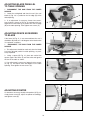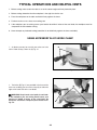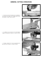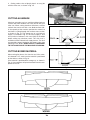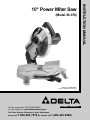
1
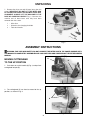
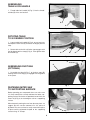
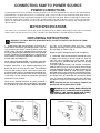
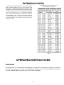
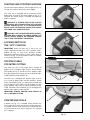
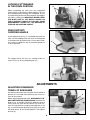
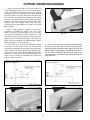
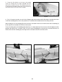
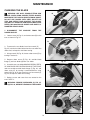
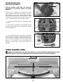
(Model 36-070)
PART NO. 899880 (0012)
Copyright © 2000 Delta Machinery
To learn more about DELTA MACHINERY
visit our website at: www.deltamachinery.com.
For Parts, Service, Warranty or other Assistance,
please call
ESPAÑOL: PÁGINA 21
1-800-223-7278 (In Canada call 1-800-463-3582).
INSTRUCTION MANUAL
10" Power Miter Saw
SAFETY RULES
Woodworking can be dangerous if safe and proper operating procedures are not followed. As with all machinery, there are certain
hazards involved with the operation of the product. Using the machine with respect and caution will considerably lessen the possibility of personal injury. However, if normal safety precautions are overlooked or ignored, personal injury to the operator may result.
Safety equipment such as guards, push sticks, hold-downs, featherboards, goggles, dust masks and hearing protection can reduce
your potential for injury. But even the best guard won’t make up for poor judgment, carelessness or inattention. Always use common sense and exercise caution in the workshop. If a procedure feels dangerous, don’t try it. Figure out an alternative procedure
that feels safer. REMEMBER: Your personal safety is your responsibility.
This machine was designed for certain applications only. Delta Machinery strongly recommends that this machine not be modified
and/or used for any application other than that for which it was designed. If you have any questions relative to a particular application, DO NOT use the machine until you have first contacted Delta to determine if it can or should be performed on the product.
Technical Service Manager
Delta Machinery
4825 Highway 45 North
Jackson, TN 38305
(IN CANADA: 505 SOUTHGATE DRIVE, GUELPH, ONTARIO N1H 6M7)
WARNING: FAILURE TO FOLLOW THESE RULES
MAY RESULT IN SERIOUS PERSONAL INJURY
1. FOR YOUR OWN SAFETY, READ INSTRUCTION MANUAL
BEFORE OPERATING THE TOOL. Learn the tool’s application
and limitations as well as the specific hazards peculiar to it.
17. USE RECOMMENDED ACCESSORIES. The use of accessories and attachments not recommended by Delta may cause
hazards or risk of injury to persons.
2. KEEP GUARDS IN PLACE and in working order.
18. REDUCE THE RISK OF UNINTENTIONAL STARTING.
Make sure switch is in “OFF” position before plugging in power
cord.
3. ALWAYS WEAR EYE PROTECTION.
4. REMOVE ADJUSTING KEYS AND WRENCHES. Form habit
of checking to see that keys and adjusting wrenches are removed
from tool before turning it “on”.
19. NEVER STAND ON TOOL. Serious injury could occur if the
tool is tipped or if the cutting tool is accidentally contacted.
20. CHECK DAMAGED PARTS. Before further use of the tool, a
guard or other part that is damaged should be carefully checked to
ensure that it will operate properly and perform its intended function – check for alignment of moving parts, binding of moving
parts, breakage of parts, mounting, and any other conditions that
may affect its operation. A guard or other part that is damaged
should be properly repaired or replaced.
5. KEEP WORK AREA CLEAN. Cluttered areas and benches
invite accidents.
6. DON’T USE IN DANGEROUS ENVIRONMENT. Don’t use
power tools in damp or wet locations, or expose them to rain.
Keep work area well-lighted.
7. KEEP CHILDREN AND VISITORS AWAY. All children and
visitors should be kept a safe distance from work area.
21. DIRECTION OF FEED. Feed work into a blade or cutter
against the direction of rotation of the blade or cutter only.
8. MAKE WORKSHOP CHILDPROOF – with padlocks, master
switches, or by removing starter keys.
22. NEVER LEAVE TOOL RUNNING UNATTENDED. TURN
POWER OFF. Don’t leave tool until it comes to a complete stop.
9. DON’T FORCE TOOL. It will do the job better and be safer at
the rate for which it was designed.
23. DRUGS, ALCOHOL, MEDICATION. Do not operate tool while
under the influence of drugs, alcohol or any medication.
10. USE RIGHT TOOL. Don’t force tool or attachment to do a job
for which it was not designed.
24. MAKE SURE TOOL IS DISCONNECTED FROM POWER
SUPPLY while motor is being mounted, connected or reconnected.
11. WEAR PROPER APPAREL. No loose clothing, gloves, neckties, rings, bracelets, or other jewelry to get caught in moving
parts. Nonslip footwear is recommended. Wear protective hair
covering to contain long hair.
25. THE DUST GENERATED by certain woods and wood products can be injurious to your health. Always operate machinery in
well ventilated areas and provide for proper dust removal. Use
wood dust collection systems whenever possible.
12. ALWAYS USE SAFETY GLASSES. Wear safety glasses.
Everyday eyeglasses only have impact resistant lenses; they
are not safety glasses. Also use face or dust mask if cutting
operation is dusty. These safety glasses must conform to ANSI
Z87.1 requirements. Note: Approved glasses have Z87 printed
or stamped on them.
WARNING: SOME DUST CREATED BY POWER
26.
SANDING, SAWING, GRINDING, DRILLING, AND OTHER
CONSTRUCTION ACTIVITIES contains chemicals known to
cause cancer, birth defects or other reproductive harm. Some
examples of these chemicals are:
• lead from lead-based paints,
• crystalline silica from bricks and cement and other masonry
products, and
• arsenic and chromium from chemically-treated lumber.
Your risk from these exposures varies, depending on how often
you do this type of work. To reduce your exposure to these
chemicals: work in a well ventilated area, and work with
approved safety equipment, such as those dust masks that are
specially designed to filter out microscopic particles.
13. SECURE WORK. Use clamps or a vise to hold work when
practical. It’s safer than using your hand and frees both hands to
operate tool.
14. DON’T OVERREACH. Keep proper footing and balance at all
times.
15. MAINTAIN TOOLS IN TOP CONDITION. Keep tools sharp
and clean for best and safest performance. Follow instructions for
lubricating and changing accessories.
16. DISCONNECT TOOLS before servicing and when changing
accessories such as blades, bits, cutters, etc.
SAVE THESE INSTRUCTIONS
2
ADDITIONAL SAFETY RULES
FOR MITER SAWS
1. USE ONLY CROSS-CUTTING SAW BLADES.
WHEN USING CARBIDE-TIPPED BLADES, MAKE
SURE THEY HAVE A NEGATIVE HOOK ANGLE. DO
NOT USE BLADES WITH DEEP GULLETS AS THEY
CAN DEFLECT AND CONTACT GUARD.
20. NEVER lock the switch in the “ON” position.
2. DO NOT OPERATE the miter saw until it is completely assembled and installed according to the instructions.
22. TURN OFF tool and wait for saw blade to stop
before moving workpiece or changing settings.
21. AFTER COMPLETING CUT, release power switch
and wait for coasting blade to stop before returning saw
to raised position.
23. DO NOT remove jammed or cut-off pieces until blade
has stopped.
3. IF YOU ARE NOT thoroughly familiar with the operation of compound miter saws, obtain advice from your
supervisor, instructor or other qualified person.
24. NEVER cut ferrous metals or masonry.
25. NEVER recut small pieces.
4. DO NOT perform any operation freehand. Secure or
clamp workpiece firmly against fence.
26. PROVIDE adequate support to the sides of the saw
table for long workpieces.
5. KEEP HANDS OUT OF PATH of saw blade. If the
workpiece you are cutting would cause your hand to be
within hazard zone of the saw blade, the workpiece
should be clamped in place before making cut.
27. NEVER use the miter saw in an area with flammable
liquids or gases.
28. NEVER use solvents to clean plastic parts. Solvents
could possibly dissolve or otherwise damage the material.
Only a soft damp cloth should be used to clean plastic
parts.
6. BE SURE blade is sharp, runs freely and is free of
vibration.
7. ALLOW the motor to come up to full speed before
starting cut.
8. KEEP motor air slots clean and free of chips.
29. DISCONNECT power before changing blades or servicing.
9. ALWAYS MAKE SURE all clamp handles are tight
before cutting, even if the table is positioned in one of the
positive stops.
30. DISCONNECT saw from power source and clean the
machine before leaving it.
10. BE SURE blade and flanges are clean and that arbor
screw is tightened securely.
31. MAKE SURE the work area is cleaned before leaving
the machine.
11. USE only blade flanges specified for your saw.
32. THE USE of attachments and accessories not recommended by Delta may result in the risk of injuries.
12. NEVER use blades larger or smaller in diameter than
ten inches.
33. SHOULD any part of your miter saw be missing,
damaged or fail in any way, or any electrical component
fail to perform properly, shut off switch and remove plug
from power supply outlet. Replace missing, damaged or
failed parts before resuming operation.
13. NEVER apply lubricants to the blade when it is
running.
14. ALWAYS check the blade for cracks or damage
before operation. Replace cracked or damaged blade
immediately.
18. NEVER reach around or behind saw blade.
34. ADDITIONAL INFORMATION regarding the safe
and proper operation of this product is available from the
National Safety Council, 1121 Spring Lake Drive, Itasca,
IL 60143-3201, in the Accident Prevention Manual for
Industrial Operation and also in the Safety Data Sheets
provided by the NSC. Please also refer to the American
National Standard Institute ANSI 01.1 Safety
Requirements for Woodworking Machinery and the U.S.
Department of Labor OSHA 1910.213 Regulations.
19. MAKE SURE blade is not contacting workpiece
before switch is turned on.
35. SAVE THESE INSTRUCTIONS. Refer to them often
and use them to instruct others.
15. NEVER use blades recommended for operation at
less than 6000 RPM.
16. DO NOT operate the saw without guards in place.
17. ALWAYS keep the lower blade guard in place and
operating properly.
3
UNPACKING
1. Remove the miter saw and all loose items from the
carton. IMPORTANT: DO NOT LIFT THE MITER SAW
BY THE SWITCH HANDLE AS THIS MAY CAUSE MISALIGNMENT. ALWAYS LIFT THE MACHINE BY THE
BASE OR CARRYING HANDLE. Fig. 2, illustrates the
machine and all loose items after they have been
removed from the carton.
1
1 - Miter Saw
2 - Wrenches for changing the blade
3 - Table lock handle
3
2
Fig. 2
ASSEMBLY INSTRUCTIONS
WARNING: FOR YOUR OWN SAFETY, DO NOT CONNECT THE MITER SAW TO THE POWER SOURCE UNTIL
THE MACHINE IS COMPLETELY ASSEMBLED AND YOU HAVE READ AND UNDERSTOOD THE ENTIRE OWNERS
MANUAL.
A
MOVING CUTTERHEAD
TO THE UP POSITION
B
1. Push down on switch handle (A) Fig. 3, and pull out
cuttinghead lockpin (B).
Fig. 3
2. The cuttinghead (C) can then be moved to the up
position, as shown in Fig. 4.
C
Fig. 4
4
ASSEMBLING
TABLE LOCK HANDLE
1. Thread table lock handle (A) Fig. 5, into the threaded hole (B) of the arm bracket.
B
A
Fig. 5
ROTATING TABLE
TO 90 DEGREE POSITION
1. Loosen table lock handle (A) Fig. 6, one or two turns
and depress index lever (B) to release 45 degree positive
stop.
2. Rotate table to the left until index stop engages with
the 90 degree positive stop (C) Fig. 6. Then tighten table
lock handle (A).
C
B
A
Fig. 6
C
A
ASSEMBLING DUST BAG
(OPTIONAL)
1. Assemble dust bag (A) Fig. 7, to the dust spout (B)
making sure the wire ring (C) is engaged with the groove
in the spout.
Fig. 7
FASTENING MITER SAW
TO SUPPORTING SURFACE
Before operating your compound miter saw, make sure
it is firmly mounted to a sturdy workbench or other supporting surface. Four holes are provided, two of which are
shown at (A) Fig. 8, for fastening the saw to a supporting
surface.
When frequently moving the saw from place to place we
suggest that the saw be mounted to a 3/4" piece of
plywood. The saw can then be easily moved from place
to place and the plywood clamped to the supporting
surface using “C” clamps.
A
Fig. 8
5
B
CONNECTING SAW TO POWER SOURCE
POWER CONNECTIONS
A separate electrical circuit should be used for your tools. This circuit should not be less than #12 wire and should be
protected with a 20 Amp time lag fuse. If an extension cord is used, use only 3-wire extension cords which have 3prong grounding type plugs and 3-pole receptacles which accept the tool’s plug. Before connecting the motor to the
power line, make sure the switch is in the “OFF” position and be sure that the electric current is of the same characteristics as indicated on the tool. All line connections should make good contact. Running on low voltage will damage the motor.
MOTOR SPECIFICATIONS
Your miter saw is wired for 110-120 volt, 60 HZ alternating current. Before connecting the miter saw to the power
source, make sure the switch is in the “OFF” position. The motor provides a no-load speed of 5200 RPM.
GROUNDING INSTRUCTIONS
WARNING: THIS TOOL MUST BE GROUNDED WHILE IN USE TO PROTECT THE OPERATOR FROM
ELECTRIC SHOCK.
Use only 3-wire extension cords that have 3-prong
grounding type plugs and 3-hole receptacles that accept
the tool’s plug, as shown in Fig. 9.
1. All grounded, cord-connected tools: In the event of a
malfunction or breakdown, grounding provides a path of
least resistance for electric current to reduce the risk of
electric shock. This tool is equipped with an electric cord
having an equipment-grounding conductor and a grounding plug. The plug must be plugged into a matching outlet
that is properly installed and grounded in accordance with
all local codes and ordinances.
Repair or replace damaged or worn cord immediately.
2. Grounded, cord-connected tools intended for use on
a supply circuit having a nominal rating less than 150
volts: This tool is intended for use on a normal 120-volt
circuit and has a grounded plug that looks like the plug
illustrated in Fig. 9.
If a properly grounded outlet is not available, a temporary
adapter, shown in Fig. 10, may be used for connecting the
3-prong grounding type plug to a 2-prong receptacle. The
temporary adapter should be used only until a properly
grounded outlet can be installed by a qualified electrician.
The green colored rigid ear, lug, or the like extending from
the adapter must be connected to a permanent ground
such as a properly grounded outlet box cover. Whenever
the adapter is used, it must be held in place with a metal
screw.
NOTE: In Canada, the use of a temporary adapter is not
permitted by the Canadian Electric Code.
Do not modify the plug provided - if it will not fit the outlet,
have the proper outlet installed by a qualified electrician.
Improper connection of the equipment-grounding conductor can result in risk of electric shock. The conductor
with insulation having an outer surface that is green with
or without yellow stripes is the equipment-grounding conductor. If repair or replacement of the electric cord or plug
is necessary, do not connect the equipment grounding
conductor to a live terminal.
Check with a qualified electrician or service personnel if
the grounding instructions are not completely understood,
or if in doubt as to whether the tool is properly grounded.
WARNING: IN ALL CASES, MAKE CERTAIN THE
RECEPTACLE IN QUESTION IS PROPERLY
GROUNDED. IF YOU ARE NOT SURE HAVE A CERTIFIED ELECTRICIAN CHECK THE RECEPTACLE.
GROUNDED OUTLET BOX
GROUNDED OUTLET BOX
CURRENT
CARRYING
PRONGS
GROUNDING
MEANS
ADAPTER
GROUNDING BLADE
IS LONGEST OF THE 3 BLADES
Fig. 9
Fig. 10
6
EXTENSION CORDS
RECOMMENDED EXTENSION CORD SIZES FOR USE
WITH STATIONARY ELECTRIC TOOLS
Use proper extension cords. Make sure your extension
cord is in good condition and is a 3-wire extension cord
which has a 3-prong grounding type plug and a 3-pole
receptacle which will accept the tool’s plug. When using
an extension cord, be sure to use one heavy enough to
carry the current of the saw. An undersized cord will
cause a drop in line voltage, resulting in loss of power
and overheating. Fig. 11, shows the correct gauge to
use depending on the cord length. If in doubt, use the
next heavier gauge. The smaller the gauge number, the
heavier the cord.
Fig. 11
OPERATING INSTRUCTIONS
FOREWORD
Delta Model 36-070 is a 10" Power Miter Saw designed to cut wood. Cross cutting and miter cutting are easy and accurate. It can crosscut up to 2-1/4" x 5-3/4", miter at 45 both left and right 2-1/4" x 4-1/8". It has positive miter stops at 0,
22.5, and 45 degrees both left and right, and is accurate to one half degree.
7
STARTING AND STOPPING MACHINE
A
To start the machine, depress switch trigger (A) Fig. 12.
To stop the machine, release the switch trigger.
This miter saw is equipped with an automatic electric
blade brake. As soon as the switch trigger (A) Fig. 12, is
released, the electric brake is activated and stops the
blade in seconds.
WARNING: A TURNING SAW BLADE CAN BE
HAZARDOUS. AFTER COMPLETING CUT, RELEASE
SWITCH TRIGGER (A) FIG. 12, TO ACTIVATE BLADE
BRAKE. KEEP CUTTINGHEAD DOWN UNTIL BLADE
HAS COME TO A COMPLETE STOP.
Fig. 12
WARNING: THE TORQUE DEVELOPED DURING
BRAKING MAY LOOSEN THE ARBOR SCREW. THE
ARBOR SCREW SHOULD BE CHECKED PERIODICALLY AND TIGHTENED IF NECESSARY.
B
LOCKING SWITCH IN
THE “OFF” POSITION
IMPORTANT: When the miter saw is not in use, the
switch should be locked in the “OFF” position using a
padlock (B) Fig. 13, (with 3/16" diameter shackle)
through the two holes (A )Fig. 12 in the switch plate, as
shown in (A) Fig. 12. NOTE: Padlock shown is available
as accessory Model 50-325.
Fig. 13
ROTATING TABLE
FOR MITER CUTTING
B
Your miter saw will cut any angle from a straight 90
degree cut to 47 degrees right and left. Simply loosen
lock handle (A) Fig. 14, one or two turns, depress index
lever (B) and move the control arm to the desired angle.
THEN TIGHTEN LOCK HANDLE (A).
The miter saw is equipped with positive stops at the 0,
22-1/2 and 45 degree right and left positions. Simply
loosen lock handle (A) Fig. 14, and move the control arm
until the bottom of the index lever (B) engages into one
of the positive stops, four of which are shown at (C).
THEN TIGHTEN LOCK HANDLE (A). To disengage the
positive stop, depress index lever (B).
IMPORTANT: ALWAYS TIGHTEN LOCK HANDLE (A)
FIG. 14, BEFORE CUTTING.
C
A
Fig. 14
A
POINTER AND SCALE
B
A pointer (A) Fig. 15, is supplied which indicates the
actual angle of cut. Each line on the scale (B) represents
1/2 degree. In effect, when the pointer is moved from one
line to the next on the scale, the angle of cut is changed
by 1/2 degree.
8
Fig. 15
LOCKING CUTTINGHEAD
IN THE DOWN POSITION
B
A
When transporting the miter saw, the cuttinghead
should always be locked in the down position. This can
be accomplished by lowering the cuttinghead (A) Fig.
16, and pushing pin (B) until other end of pin (B) engages
with hole in cutting arm. IMPORTANT: NEVER CARRY
THE MITER SAW BY THE SWITCH HANDLE OR
TABLE CONTROL HANDLE AS THIS MAY CAUSE
MISALIGNMENT. ALWAYS LIFT THE MACHINE BY
THE BASE OR CARRYING HANDLE.
Fig. 16
REAR SUPPORT/
CARRYING HANDLE
A rear support bar (A) Fig. 17, is provided to prevent the
miter saw from tipping to the rear when the cuttinghead
is returned to the up position after a cut has been made.
For maximum support the bar (A) should be pulled out
as far as possible.
A
Fig. 17
The support bar (A) also acts as a carrying handle, as
shown in Fig. 18, when transporting the saw.
Fig. 18
ADJUSTMENTS
ADJUSTING DOWNWARD
TRAVEL OF SAW BLADE
The downward travel of the saw blade can be limited to
prevent the saw blade from contacting any metal surfaces of the machine.
Before adjusting downward travel, DISCONNECT THE
MACHINE FROM THE POWER SOURCE and lower the
blade as far as possible. Rotate the blade by hand to
make certain the teeth do not contact any metal surfaces.This adjustment is made by loosening lock nut (A)
Fig. 19, and turning the adjusting screw (B) in or out until
the blade lowers to the desired position. Then tighten
lock nut (A).
A
B
9
Fig. 19
ADJUSTING BLADE PARALLEL
TO TABLE OPENING
1. DISCONNECT THE SAW FROM THE POWER
SOURCE.
2. Lower the cuttinghead and check to see if the saw
blade (A) Fig. 20, is parallel to the left edge (B) of the
table opening.
A
3. If an adjustment is necessary, loosen two screws,
one of which is shown at (C) Fig. 20, and move the cuttinghead until the blade (A) is parallel with the left edge
(B) of the table opening. Then tighten two screws (C).
C
B
Fig. 20
ADJUSTING FENCE 90 DEGREES
TO BLADE
A
A
If the fence (A) Fig. 21, is ever removed from the saw it
should be adjusted so it is 90 degrees to the blade when
it is replaced, as follows:
1. DISCONNECT THE SAW FROM THE POWER
SOURCE.
2. This adjustment should be made only after the blade
has been adjusted parallel to table opening, as previously explained.
B
Fig. 21
3. Using a square (B) Fig. 21, place one end of the
square against the fence (A) and the other end against
the slot in the table as shown.
C
C
4. If an adjustment is necessary, loosen the two screws
(C) Fig. 22, and adjust fence 90 degrees to the table
opening. Then tighten the two screws (C).
Fig. 22
A
B
ADJUSTING POINTER
If it becomes necessary to adjust the pointer (A) Fig. 23,
simply loosen screw (B), adjust the pointer accordingly
and tighten screw (B).
Fig. 23
10
TYPICAL OPERATIONS AND HELPFUL HINTS
1. Before cutting, make certain the table is set at the correct angle and firmly locked in place.
2. Before cutting, determine that the workpiece is the right size for the saw.
3. Place the workpiece on the table and hold it firmly against the fence.
4. For best results cut at a slow, even cutting rate.
5. If the workpiece you are cutting causes your hand to be within 4 inches of the saw blade, the workpiece must be
clamped to the fence before cutting.
6. Never attempt any freehand cutting (wood that is not held firmly against the fence and table).
USING ACCESSORY 36-221 WORK CLAMP
A
1. An ideal accessory for use with your miter saw is the
36-221 Work Clamp, shown at (A) Fig. 24.
Fig. 24
2. Two holes (B) Fig. 25, are provided in the base of the
miter saw enabling you to use the clamp (A) on either the
right or left hand side of the saw blade.
B
WARNING: Keep hands out of path of saw blade.
If the workpiece you are cutting would cause your
hand to be within 4 inches of the saw blade, the
workpiece should be clamped in place before making cut.
A
Fig. 25
11
GENERAL CUTTING OPERATIONS
1. Your miter saw has the capacity to cut standard 2 x
4’s laying flat or on edge, at the 45 degree right and left
miter angles as shown in Figs. 26 and 27.
Fig. 26
Fig. 27
2. A standard 2 x 6 can easily be cut in the 90 degree
straight cut-off position in one pass, as shown in Fig. 28.
Fig. 28
3. Cutting a standard 4 x 4 is easily accomplished with
your miter saw in one pass, as shown in Fig. 29.
Fig. 29
12
4. Cutting various sizes of plastic pipe is an easy job
with the miter saw, as shown in Fig. 30.
CUTTING ALUMINUM
Aluminum extrusions such as used for making aluminum
screens and storm windows can easily be cut with your
miter saw. When cutting aluminum extrusions, or other
sections that can be cut with a saw blade and are within the capacity of the machine, position the material so
the blade is cutting through the smallest cross-section,
as shown in Fig. 31. The wrong way to cut aluminum
angles is illustrated in Fig. 32. Be sure to apply a stick
wax (similar to Johnson’s stick wax #140) to the blade
before cutting any aluminum stock. This stick wax is
available at most industrial mill supply houses. The stick
wax provides proper lubrication and keeps chips from
adhering to the blade. NEVER APPLY A LUBRICANT
TO THE BLADE WHILE THE MACHINE IS RUNNING.
Fig. 30
Fig. 31
CUTTING BOWED MATERIAL
When cutting flat pieces, first check to see if the material is bowed. If it is, make sure the material is positioned
on the table as shown in Fig. 33.
If the material is positioned the wrong way, as shown in
Fig. 34, the workpiece will pinch the blade near the completion of the cut.
Fig. 32
Fig. 33
Fig. 34
13
CUTTING CROWN MOULDINGS
1. There are several methods that can be used to cut
crown mouldings on the miter saw. The method shown
in Fig. 35, illustrates the contact surfaces (the surfaces
that contact the wall and ceiling) of the crown moulding
held firmly against the fence and table of the miter saw.
This method is acceptable when making a small number
of cuts but would not be practical for a production application as it may be difficult to firmly hold the work in this
position. Also, this method means that the crown
moulding must be positioned on the table in the upside
down position.
2. When a large number of repetitive cuts of crown
moulding are required we suggest the use of filler
blocks, as shown in Fig. 36 through Fig. 39. The majority of crown mouldings have contact surfaces at 52 and
38 degrees to the rear surface of the moulding and these
angles must be utilized when jointing the face of the filler
block. For crown mouldings with different angles, appropriate filler blocks can be produced.
Fig. 35
3. Fig. 36 and Fig. 37, illustrate the filler block fastened
to the miter saw fence with the face of the filler block
extending outward from the top of the fence and down
to the surface of the table. When the filler block is positioned in this manner, the crown moulding must be positioned on the table in the upside down position. This
means that the surface of moulding that contacts the
ceiling is against the table.
4. Fig. 38 and Fig. 39, illustrate the filler block fastened
to the miter saw fence with the face of the filler block
extending inward toward the fence from the top to the
bottom. When the filler block is positioned in this manner, the crown moulding is placed on the table in the
same position as it would be when nailed between the
ceiling and wall.
FILLER BLOCK FOR CROWN MOULDING IF JOINT IS TO HAVE MITERED
CORNER FIT OR COPE CUT
FILLER BLOCK FOR CROWN MOULDING IF JOINT IS TO HAVE MITERED
CORNER FIT OR COPE CUT
Fig. 36
Fig. 38
Fig. 37
Fig. 39
14
5. Fasten the filler blocks to the fence using wood
screws (A) through the two holes provided on each
fence half, as shown in Fig. 40. This enables you to easily remove the filler blocks when not in use and quickly
reassemble them to the fence when needed.
A
A
Fig. 40
6. Fig. 41, illustrates the miter saw arm in the 45 degree right miter position and the filler blocks fastened to the fence
so that the moulding will be in the same position as it would be when nailed between the ceiling and wall.
When making this cut the moulding (B) on the left of the saw blade will be for an outside corner and the moulding (C)
on the right of the saw blade will be for an inside corner.
To cut the mating pieces for mouldings (B) and (C) Fig. 41, simply rotate the miter saw arm to the 45 degree left miter
position and make the cut, as shown in Fig. 42. In this case the moulding (D) on the left of the saw blade will be for an
inside corner and the moulding (E) on the right of the saw blade will be for an outside corner.
E
D
B
C
Fig. 42
Fig. 41
15
MAINTENANCE
CHANGING THE BLADE
A
WARNING: USE ONLY CROSS-CUTTING SAW
BLADES. WHEN USING CARBIDE TIPPED BLADES,
MAKE SURE THEY HAVE A NEGATIVE HOOK ANGLE.
DO NOT USE BLADES WITH DEEP GULLETS AS
THEY CAN DEFLECT AND CONTACT THE GUARD.
USE ONLY 10" DIAMETER SAW BLADES WHICH ARE
RATED FOR 6000 RPM OR HIGHER AND HAVE 5/8"
DIAMETER ARBOR HOLES.
1. DISCONNECT
POWER SOURCE.
THE
MACHINE
FROM
B
THE
Fig. 43
2. Loosen screw (A) Fig. 43, and rotate cover (B) to the
rear as shown in Fig. 44.
B
3. To remove the saw blade, insert hex wrench (C)
Fig. 45, into the hex hole located on the rear end of the
arbor shaft, to keep the shaft from turning.
4. Using wrench (D) Fig. 46, loosen arbor screw (E) by
turning it clockwise
5. Remove arbor screw (E) Fig. 46, outside blade
flange (F) and saw blade (G) from saw arbor.
Fig. 44
6. Assemble new saw blade MAKING CERTAIN TEETH
OF SAW BLADE ARE POINTING DOWN AT THE FRONT
and re-assemble outside blade flange (F) Fig. 46, and
arbor screw (E) by turning it counterclockwise using
wrench (D) Fig. 46. At the same time use hex wrench (C)
Fig. 45, to keep the arbor from turning.
C
7. Replace screw and cover that was rotated to the
rear in STEP 2.
WARNING: REMOVE WRENCHES (C) FIG. 45,
AND (D) FIG. 46, BEFORE TURNING ON THE POWER.
Fig. 45
E
F
G
D
Fig. 46
16
BRUSH INSPECTION
AND REPLACEMENT
B
CAUTION: BEFORE INSPECTING THE BRUSHES,
DISCONNECT THE MACHINE FROM THE POWER
SOURCE.
A
Brush life varies. It depends on the load on the motor.
Check the brushes after the first 50 hours of use for a
new machine or after a new set of brushes has been
installed. After the first check, examine them after about
10 hours of use until such time that replacement is necessary. To inspect the brushes, proceed as follows:
A
Fig. 47
D
1. Remove three screws (A) Fig. 47, and remove motor
cover (B).
2. The brushes are located in the two holders (C) Fig.
48. Remove spade type terminal connector (D) and pull
out brush holders (C).
D
C
C
Fig. 48
3. Fig. 49, illustrates one of the brushes (E) removed
from the holder (C). When the carbon on either brush (E)
is worn to 3/16" in length or if either spring (F) or shunt
wire is burned or damaged in any way, replace both
brushes. If the brushes are found serviceable after
removing, reinstall them in the same position as
removed.
F
E
C
Fig. 49
TABLE HAZARD AREA
WARNING: THE AREA INSIDE THE TWO RED LINES (A) FIG. 50, ON THE TABLE IS DESIGNATED AS A HAZARD ZONE. NEVER PLACE YOUR HANDS INSIDE THIS AREA WHILE THE TOOL IS BEING OPERATED.
A
Fig. 50
17
NOTES
18
NOTES
19
ACCESSORIES
A complete line of accessories are available from your Delta Supplier, Porter-Cable Delta Factory
Service Centers, and Delta Authorized Service Stations. Please visit our Web Site
www.deltamachinery.com for a catalog or for the name of your nearest supplier.
WARNING: Since accessories, other than those offered by Delta, have not been tested with
this product, use of such accessories could be hazardous. For safest operation, only Delta
recommended accessories should be used with this product.
36-221
36-222
Work Clamp
Dust Bag
PARTS, SERVICE OR WARRANTY ASSISTANCE
All Delta Machines and accessories are manufactured to high quality standards and are serviced by
a network of Porter-Cable Delta Factory Service Centers and Delta Authorized Service Stations. To
obtain additional information regarding your Delta quality product or to obtain parts, service, warranty
assistance, or the location of the nearest service outlet, please call 1-800-223-7278 (In Canada call
1-800-463-3582).
Delta Building Trades and Home Shop Machinery
Two Year Limited Warranty
Delta will repair or replace, at its expense and at its option, any Delta machine, machine part, or machine accessory which
in normal use has proven to be defective in workmanship or material, provided that the customer returns the product prepaid to a Delta factory service center or authorized service station with proof of purchase of the product within two years
and provides Delta with reasonable opportunity to verify the alleged defect by inspection. Delta may require that electric
motors be returned prepaid to a motor manufacturer’s authorized station for inspection and repair or replacement. Delta
will not be responsible for any asserted defect which has resulted from normal wear, misuse, abuse or repair or alteration
made or specifically authorized by anyone other than an authorized Delta Service facility or representative. Under no circumstances will Delta be liable for incidental or consequential damages resulting from defective products. This warranty
is Delta’s sole warranty and sets forth the customer’s exclusive remedy, with respect to defective products; all other warranties, express or implied, whether of merchantability, fitness for purpose, or otherwise, are expressly disclaimed by Delta.
Printed in U.S.A.
20
PORTER-CABLE DELTA SERVICE CENTERS
(CENTROS DE SERVICIO DE PORTER-CABLE DELTA)
Parts and Repair Service for Porter-Cable/Delta Power Tools are Available at These Locations
(Obtenga Refaccion de Partes o Servicio para su Herramienta en los Siguientes Centros de Porter-Cable Delta)
ARIZONA
Tempe 85282 (Phoenix)
2400 West Southern Avenue
Suite 105
Phone: (602) 437-1200
Fax: (602) 437-2200
CALIFORNIA
Ontario 91761 (Los Angeles)
3949A East Guasti Road
Phone: (909) 390-5555
Fax: (909) 390-5554
San Leandro 94577 (Oakland)
3039 Teagarden Street
Phone: (510) 357-9762
Fax: (510) 357-7939
COLORADO
Denver 80216
5855 Stapleton Drive North
Suite A-140
Phone: (303) 370-6909
Fax: (303) 370-6969
FLORIDA
Davie 33314 (Miami)
4343 South State Rd. 7 (441)
Unit #107
Phone: (954) 321-6635
Fax: (954) 321-6638
Tampa 33609
4538 W. Kennedy Boulevard
Phone: (813) 877-9585
Fax: (813) 289-7948
GEORGIA
Forest Park 30297 (Atlanta)
5442 Frontage Road,
Suite 112
Phone: (404) 608-0006
Fax: (404) 608-1123
ILLINOIS
Addison 60101 (Chicago)
311 Laura Drive
Phone: (630) 628-6100
Fax: (630) 628-0023
Woodridge 60517 (Chicago)
2033 West 75th Street
Phone: (630) 910-9200
Fax: (630) 910-0360
MARYLAND
Elkridge 21075 (Baltimore)
7397-102 Washington Blvd.
Phone: (410) 799-9394
Fax: (410) 799-9398
MASSACHUSETTS
Braintree 02185 (Boston)
719 Granite Street
Phone: (781) 848-9810
Fax: (781) 848-6759
Franklin 02038 (Boston)
Franklin Industrial Park
101E Constitution Blvd.
Phone: (508) 520-8802
Fax: (508) 528-8089
MICHIGAN
Madison Heights 48071 (Detroit)
30475 Stephenson Highway
Phone: (248) 597-5000
Fax: (248) 597-5004
MINNESOTA
Minneapolis 55429
4315 68th Avenue North
Phone: (612) 561-9080
Fax: (612) 561-0653
MISSOURI
North Kansas City 64116
1141 Swift Avenue
P.O. Box 12393
Phone: (816) 221-2070
Fax: (816) 221-2897
OREGON
Portland 97230
4916 NE 122 nd Ave.
Phone: (503) 252-0107
Fax: (503) 252-2123
St. Louis 63119
7574 Watson Road
Phone: (314) 968-8950
Fax: (314) 968-2790
PENNSYLVANIA
Willow Grove 19090
520 North York Road
Phone: (215) 658-1430
Fax: (215) 658-1433
NEW YORK
Flushing 11365-1595 (N.Y.C.)
175-25 Horace Harding Expwy.
Phone: (718) 225-2040
Fax: (718) 423-9619
NORTH CAROLINA
Charlotte 28270
9129 Monroe Road, Suite 115
Phone: (704) 841-1176
Fax: (704) 708-4625
OHIO
Columbus 43214
4560 Indianola Avenue
Phone: (614) 263-0929
Fax: (614) 263-1238
Cleveland 44125
8001 Sweet Valley Drive
Unit #19
Phone: (216) 447-9030
Fax: (216) 447-3097
TENNESSEE
Nashville 37214
2262 Lebanon Pike
Phone: (615) 882-0320
Fax: (615) 882-0051
TEXAS
Carroliton 75006 (Dallas)
1300 Interstate 35 N, Suite 112
Phone: (972) 446-2996
Fax: (972) 446-8157
Houston 77055
West 10 Business Center
1008 Wirt Road, Suite 120
Phone: (713) 682-0334
Fax: (713) 682-4867
WASHINGTON
Renton 98055 (Seattle)
268 Southwest 43rd Street
Phone: (425) 251-6680
Fax: (425) 251-9337
Authorized Service Stations are located in many large cities. Telephone 800-487-8665 or 901-541-6042 for assistance locating one.
Parts and accessories for Porter-Cable Delta products should be obtained by contacting any Porter-Cable Delta Distributor, Authorized
Service Center, or Porter-Cable Delta Factory Service Center. If you do not have access to any of these, call 888-848-5175 and you will
be directed to the nearest Porter-Cable Delta Factory Service Center. Las Estaciones de Servicio Autorizadas están ubicadas en muchas
grandes ciudades. Llame al 800-487-8665 ó al 901-541-6042 para obtener asistencia a fin de localizar una. Las piezas y los accesorios
para los productos Porter-Cable Delta deben obtenerse poniéndose en contacto con cualquier distribuidor Porter-Cable Delta, Centro
de Servicio Autorizado o Centro de Servicio de Fábrica Porter-Cable Delta. Si no tiene acceso a ninguna de estas opciones, llame al
888-848-5175 y le dirigirán al Centro de Servicio de Fábrica Porter-Cable Delta más cercano.
CANADIAN PORTER-CABLE
DELTA SERVICE CENTERS
ALBERTA
MANITOBA
QUÉBEC
Bay 6, 2520-23rd St. N.E.
Calgary, Alberta
T2E 8L2
Phone: (403) 735-6166
Fax: (403) 735-6144
1699 Dublin Avenue
Winnipeg, Manitoba
R3H 0H2
Phone: (204) 633-9259
Fax: (204) 632-1976
1515 ave.
St-Jean Baptiste,
Québec, Québec
G2E 5E2
Phone: (418) 877-7112
Fax: (418) 877-7123
BRITISH COLUMBIA
8520 Baxter Place
Burnaby, B.C.
V5A 4T8
Phone: (604) 420-0102
Fax: (604) 420-3522
ONTARIO
505 Southgate Drive
Guelph, Ontario
N1H 6M7
Phone: (519) 836-2840
Fax: (519) 767-4131
1447, Begin
St-Laurent, (Montréal),
Québec
H4R 1V8
Phone: (514) 336-8772
Fax: (514) 336-3505
The following are trademarks of PORTER-CABLE DELTA Corporation (Las siguientes son marcas registradas de PORTER-CABLE S.A.):
BAMMER®, INNOVATION THAT WORKS®, JETSTREAM®, LASERLOC®, OMNIJIG®, POCKET CUTTER®, PORTA-BAND®, PORTA-PLANE®,
PORTER-CABLE®, QUICKSAND®, SANDTRAP®, SAW BOSS®, SPEED-BLOC®, SPEEDMATIC®, SPEEDTRONIC®, STAIR-EASE®, THE PROFESSIONAL EDGE®, THE PROFESSIONAL SELECT®, TIGER CUB®, TIGER SAW®, TORQBUSTER®, WHISPER SERIES®, DURATRONIC™,
FLEX™, FRAME SAW™, MICRO-SET™, MORTEN™, NETWORK™, RIPTIDE™, TRU-MATCH™, WOODWORKER’S CHOICE™.
Trademarks noted with ® are registered in the United States Patent and Trademark Office and may also be registered in other countries.
Las Marcas Registradas con el signo de ® son registradas por la Oficina de Registros y Patentes de los Estados Unidos y también pueden
estar registradas en otros países.
Printed in U.S.A.