1
INTRODUCTION
CONGRATULATIONS on the purchase of your new MONTAGUE
BIFRAME bicycle. This manual is designed to give you the information you need for the safe operation and maintenance 'of your
new bicycle. Please read it thoroughly before riding your bicycle.
TABLE OF CONTENTS
Introduction.
. .. I
Owner's Responsibi Iity
.. ... 2
.
Parts of Your Bicycle & Location of Quick Releases ..
Operation of Quick Releases
. .3
.
. ... , .... .4-5
Folding the Montague BiFrame
6-11
Unfolding the Montague BiFrame
12
Safety on the Road
13
Inspection and Maintenance
14-15
.
BiFrame Special Assembly Instructions ...
..
Racks. Fenders and Other Accessories ..
16
.
19-20
Handlebar and Stem
.
21
Rcflcctor~
......................................... 22
Brakes
.
Derailleurs
Bearings and Tires
.
COLOR ..
DATE OF PURCHASE
PLACE OF PURCHASE.
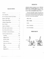
PROPER FRAME FIT
Ih".To 2"
.. ...... 23
..
Brake Levers anJ Shift Levers ..
SERIAL NUMBER
17
Front Wheel..............................
Pedals and
..
.19-32
Assembly and Adjustment Instructions ..
Seat Post and Saddle
MODEL NAME
.. .. 18
Tools Needed for Assembly and Maintenance ...
.
Your bicycle's serial number is stamped on the underside of the
bol1om bracket shell. Record the serial number in this manual in the event
that your bicycle is lost or stolen. You may also want to register your
serial number with your local police department.
.
24
.
25-27
28-31
32
Figure I
OWNER'S RESPONSIBILITY
Before riding your BiFrame bicycle, carefully follow all assembly
instructions. Make sure that all nuts, bolts and screws are securely
tightened.
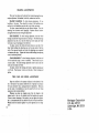
PARTS OF YOUR BICYCLE
AND
LOCATION OF BIFRAME QUICK RELEASES
Make sure this bicycle fits the intended rider. Bicycles come in a
variety of sizes. Personal adjustment of seat and handleb~rs is necessary
to as'sure maximum safety and comfort. Bicycles come with a wide variety
of equipment and ac~essories; make sure that the rider can operate them.
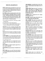
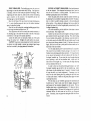
Check the seat position, adjusting it up or down so that with the ball
of the rider's foot on the pedal in its lowest position. the rider's knee
is slightly bent. Rider should also be able to straddle the bicycle with
between 1.5" to 2" clearance above 'the top tube when standing with
both feet on the ground. Measurement for a woman's bike should be
determined using amen's model as a· basis (Figure 1).
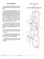
All five of the BiFrame's quick releases must be securely fastened
b~fore riding the bicycle. The five quick releases are (I) the front wheel
qutek release lev.er. (2) the front brake quick release, (3) the seat quick
release lever and (4 & 5) the top and bottom seat tube quick release levers
(Figure 2).
Make sure that apyone to whom you loan your BiFrame understands
how to work the quick release levers and how to fold and unfold the
BiFrame properly.
The owner is responsible for required normal maintenance services,
such as those listed in the ~;ection "Inspection and Maintenance" in th)s
booklet, to keep the bicycle in good operating condition.
The manufacturer is not responsible for failure, injury. or damage
caused by improper completion of assembly or improper maintenance
after shipment.
2
3
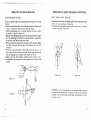
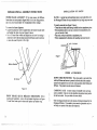
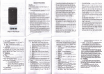
OPERATION OF QUICK RELEASES
QUICK RELEASE LEVERS:
Great care should be taken when locking the quick release levers on the
bicycle:
• Move the quick release lever to the wide open position so that the word
"open" on the lever faces out, away from the bicycle.
• Tighten the adjusting nut in a clockwise direction by hand as lightly
as possible, as shown in Figure 3a.
• Flip the lever 180 degrees up aod over to the closed position (Figure
3b). You should begin to feel the lever resist movement as it approaches
the halfway point between open and closed.
• If the lever does not provide finn resistance, move the quick release
lever back to the open position and turn the adjusting nut a half turn
clockwise.
• If the lever can not be pushed in flush with the bike because it is too
tight. move the quick release lever back into the open position and
turn the adjusting nut one quarter turn counter clockwise.
• Repeat until' you feel resistance slightly past the halfway point.
• It should take a lot of pressure for you to push the lever into the closed
position.
OPERAnON OF QUICK RELEASES (CONTINUED)
- FRONT BRAKE QUICK RELEASE:
• To loosen the front brake for folding, pull the front brake quick release
tab so thaI it is pointing up. (Figure 4a)
• To tighten the front brake for riding push the tab so that it is pointing
towards the ground. (Figure 4b).
Figure 4a
Figure 4b
Figure 3a
t"lgure 3b
4
CAUTION: It is very important tha'tyou use the quick releases properly
to ensure the safe operation of your bicycle. If any of the procedures
is unclear. have an authorized bicycle dealer demonstrate the proper
procedures to you.
5
'~-"
........
,
FOLDING'THE MONTAGUE BIFRAME
The Montague BiFrame has been designed to fold and unfold quickly
and easily, without requiring. any tools. A few simple steps must be
followed. however. in order to assure safe operation and to avoid
scrat~hing or damaging the bicycle while it is being folded and unfolded.
"..r ·
.' • -'-I • '~' ..
"....
:'.
·I~
,
.....
. '_'"
~. ~.f'. ~.
.1,:
,'. •
.' '1..:- .~' " ::.. -.';.:
.
.
"
~
.
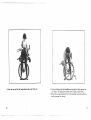
• Stand on the chain side of the BiFrame.
• Unlock the two quick release levers located on the seat tube.
• A third quick release lever located at the top of the seat tube can be
used to lower the seat.
"'J
'
!
1
6
• Unlock the front brake quick release.
• Unlock the front wheel quick release lever. You will have to rotate
the adjusting nut counter-clockwise several times before the wheel will
come off the fork.
• Remove the wheel and set it aside.
~..-.:---
"::;:':.:..".::.."::":'-~-;.....-:-.-.:...'':.:.:''::':"(~'..""._.-:.::...
.. 'c:.:"':";""c2!\.:,,:,'''..i.;'',,,,,,.'./C:-.,.:..:.''.:.c'
...c..c.:=~=-;.....'.;.:;!_,.:::.·.-:;
..:.:::,r=~:.:::--;.....'':::''
,'-'..'1,',,,,,,.. 'C:...',,-,
••' ~:..o."
'--,-,-,:-"
,.''..•
, c..:.'
:... . .'
Figure Sa
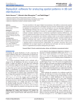
• Stand the BiFrame on end. Place your feet on either side of the rear
wheel so that it doesn't roll around.
• Turn the handl~bars so that they are facing away from you.
• Align the. pedals so that the pedal closest to you is at the bottom of
its swing, pointed directly to your right.
8
Figure 5b
• Hold the handlebars (or the han<:\lebar stem) with your right hand
• Hold the seat post with your left hand and with your left thumb. unlock
the safety latch under the seat by moving the latch frnm the position
shown in Fig Sa to the position shown in Fig, 5h
9
·~,
~ _
'
,'.
: •• c'
.::...,.".,
.1...:.:.... •.. ~ ••• ',
.
• Push the top half of the frame'down and away from you.
10
• Continue folding until the handlebars are pusbed in tightly against the
rear wheel. The pedal arms should now be able to spin freely.
• Relock the two quick release levers on the seat tube to prevent unfolding
during transport or storage.
11
SAFETY ON THE ROAD
UNFOLDING THE MONTAGUE BIFRAME
Wear a helmet that meets Ansi Z290.4 requirements.
• To unfold the BiFrame, first loosen the seat tube quick release levers.
• Rotate the pedals so that the pedal on the chain side of the BiFrame
is at the bottom of its swing pointed away from the seat.
• Grabbing the handlebar stem with your right hand, and the back wheel
with your left hand, pull open the BiFrame, until the safety latch snaps
into place.
• Tighten the two seat tutie quick release levers.
• Put the front wheel back on the bicycle, tightening the front wheel quick
release lever (see instructions on page 19).
• Tighten the front brake quick release
• Raise the seat as necessary.
• While the BiFrame is equipped with an automatic safety latch for your
protection. this safety latch is designed to be used only in conjunction
with the quick release mechanisms.
Observe all traffic regulations. Obey red and green lights, one·way
streets, stop signs, etc.
Ride with the traffic, not against It. Ride single file in a straight
line.
Have satisfactory signaling device to warn of approach.
Give pedestrians the right of way.
Slow down at all street intersections and look to the right and left
before crossing.
Always use proper hand signals for turning and stopping.
Watch for cars pulling out into traffic and for sudden opening of
car doors.
Make sure the safety latch is in the locked position shown in
Fig. 5a before riding the bicycle.
Avoid potholes, drainage grates or other road
Cross railroad tracks at a right angle.
NOTE: The BiFrame can sometimes get caught in the folded position.
This can happen when the bicycle is not folded flat enough which causes
the pedal and crank arm to hit the down tube when rotated. If this
happens, manually turn the rear wheel in the direction it would spin if
the bicycle were being ridden. At the same time, turn the pedal and crank
arm in the same direction until they are in the proper position for
unfolding.
Never hitch on other vehicles, do not "Stunt" ride or race in'
traffic. Don't weave in and out of traffic or swerve from side to side.
CAUTION: It is very important to lock all five quick releases securely
before riding: (I) the front wheel quick relea'se lever. (2) the front brake
quick release, (3) the seat quitk release lever and (4 & 5) the top and
bottom seat tube quick release levers.
CAUTION IN WET WEATHER RIDING
su~face
hazards.
Never carry other riders or packages that obstruct vision or proper
control of the bicycle.
Before riding, check your brakes. Be sure they are operating
efficiently and that your bicycle -is in perfect running condition.
No brakes work as well under wet conditions as.they do under dry
conditions. In rainy or wet weather. special precautions must be taken
to insure safety in stopping. Proper adjustment and cable lubrication will
help, but the major precaution res~ with you. Increased lever forces are
required on wet or rainy weather arid care must be exercised to maintain
safety under these conditions. Ride slower than normal and apply your
brakes sooner than normal conditions would require.
If you do not understand how to fold and unfold the BiFrame. be
sure to ask your dealer for assistance.
13
I :2
-~
.......
;;:'"
...
.;~
~~~
..-"
...... ..-.""
'
.-.'~'
. --" ,. .... ---
~_.
~
... _..-.
-_.-
CRANK BEARINGS: Crank assembly should turn freely without
side play. Keep locknut tight and keep bearings clean and well
adjusted .
INSPECTION AND MAINTENANCE
. SAFETY LATCH: The safety latch located at the top of the seat tube
must be kept clean and well lubricated. Once every six months or sooner
if necessary. a few drops of a lightweight all-purpose lubricating oil
should be applied to the latch pin.
CRANKS & PEDALS: Replace bent cranks. Do not attempt to
straighten. Check crank bolt or nut (depending on axle type)
regularly to make sure crank arms stay tight. Replace pedals if
bearings are tight or frozen and if thread is lost or badly worn.
Keep pedal bearings lubricated.
SEAT TUBES: The BiFrarne folds using concentric seat tubes. These
tubes must be lubricated on a regular basis. at least once every six months
or sooner, if the BiFrame becomes difficult to fold. Keep the Bi-Frarne
stored indoors. Do not allow water to enter into the seat tubes. A grease
valve. located behind the water bonle braze-ons on the seat tube, is provided for this pUf"!'Ose. To lubricate the seat tubes:
CHAINRINGS: Replace if chainring teeth are bent or damaged.
Keep chainrings tight on crank.
REAR WHEEL: Keep axle nuts tight and wheel centered in chainstays. Keep spokes tight and wheel properly aligned.
WHEEL ALIGNMENT: Wheels should rotate smoothly without
wobbling from side to side. Have them aligned (trued) if necessary.
• Attach a grease gun to the grease valve. (Grease guns are available
at hardware stores.)
• Force grease into the scat tube with the grease gun.
• Continue until grease is escaping through the top and the bottom of
(he seat tube. indicating that the entire tube has been greased.
HANDLEBAR: Adjust for your comfort. Make sure minimum
insertion mark on the stem remains inside the frame. Tighten
securely. Replace worn grips. Make sure they fit snugly.
,
CHAIN: Check frequently for damage and stretch and readjust if
necessary. Lubricate several times each season. Use a lightweight
all-purpose oil, being careful to oil each link.
INSPECTIOl'i: Every week .or two tighten all nuts and bolts. Check
all hardware to see that no parts are worn or damaged, that there is correct
fork and frame alignment. and that all components are seated in proper
position.
DERAILLEUR UNITS: Shift levers only while pedaling. Keep
units adjusted. Do not allow bicycle to fall on derailleur units.
Keep derailleurs and freewheel lubricated.
BRAKES Keep brake shoes adjusted to rim. Replace worn or missing
shoes. Do not wax or oil rim. Keep brake cables and brake pivot bushing
lubricated.
I
SEAT ADJUSTMENT: Adjust for,comfort of the rider. Be sure
that minimum insertion l1\ark on seat post remains ;n the frame.
Securely tighten the seat post binder bolt and position the angle
of seat for comfort of the rider. Securely tighten seat post binder
bolt until seat will no longer tum.
COASTER BRAKE: Be sure that brake operates smoothly without
locking or grabbing when applied normally. Keep brake arm securely
fastened to bicycle frame. Have checks made on brake periodically for
'" l:ar on interior discs or shoes.
TIRES: Make sure that tires are inflated according. to pressure
indication on tire sidewalL· A foot or frame pump should be used.
Pressurized unregulated pumps should not be used. The tire should
be properly seated in the rim and .the fitting of the tire bead and
rim bead should be checked.
COl'iTROL CABLES: R'eplace worn or damaged cables. Do not kink
cables. Cables stretch with use; adjust accordingly. Keep control cable
lubricated.
FRONT FORK: Bent or damaged for should be replaced. Never attempt to repair by straightening.
REFLECTORS: Reflecto~ should be kept clean, securely fastened
and positioned for bicycle identification at night from front,
rear and lateral visibility. Damaged units should be promptly
replaced.
HEAD BEARINGS: Keep tight and iubricated. The handlebar must tum
freely.
FRONT WHEEL: Keep axle nuts tight. Wheel should be centered in
fork. Keep wheel bearings adjusted and keep spokes tight and wheel in
proper alignment.
FRAME: Immediately replace a bent or broken frame. Frame
damage can cause excess stress or failure in other bicycle parts.
l~
~
....
....... r' ...... ~...-.'
rr;-"'~"'i:'r.~.-.·
--~~.
-,.
• -..
- .. -. -
.-
-
15
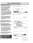
BIFRAME SPECIAL ASSEMBLY INSTRUCTIONS
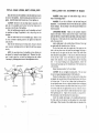
INSTALLA TION OF RACKS
PROPER FRAME AUGNMENT: If, for some reason, the BiFrame
frame does not seem properly aligned while it is in the riding position.
take it to your bicycle dealer for re-adjustment before riding it.
RACKS: A special rear racIc attachment piece is provided free with
the Montague BiFrame for easy installation of any single stay rear rack.
To correct the frame alignment:
• Locate the special set screw located below the bottom bracket shell
and behind the chain ring (see Figure 6 below).
• Use a 2.0 rom Allen wrench and adjust the set screw by turning it
ciockwise to ml)Ve the rear drop-outs to the left and counter-clockwise
to move the r<.:ar drop-outs to the right.
To install a rear rack (see Figure 7 below):
• Thread the rear brake cable through middle bole on attachment piece.
• Bolt auaebment piece to seat stay connector bar (attachment piece
goes on far side of bar).
• Place rack on bicycle and bolt to attachment piece.
• Follow manufacturer's directions for installing rack onto bicycle.
1
I
#
Figure 7
OTHER ACCESSORIES
DOWN TUBE PROTECTOR: This nylon patch is provided free
with the BiFrame and serves to protect the down lUbe from scratches
caused by the pedal if it is not in the correct position while folding the
BiFrame. 1be protector can be removed if desired.
Figure 6
FRONT BRAKE QUICK RELEASE MECHANISM: Before
installing the handlebars. remove the top headsef ring shown in Figure
2. Install front brake quick release and replace top headset ring.
CARRYING CASE: A water resistant Cordura® nylon carrying
case is available. It has a., over-the-shoulder strap and an inner pocket
for the front wheel. See your dealer formore details.
)
\
Other exciting accessories are in the process of being developed for the
Montague BiFrame. If you mail in your owner's registration card. we
will keep you posted on the latest developments.
16
17
-
~.-."r.~_'_'"
.0.",
q,,:"''''-.~''-'-'
''''.", -, "
.••..
_
.
TOOLS NEEDED FOR ASSEMBLY AND MAINTENANCE
ASSEMBLY AND ADJUSTMENT INSTRUCTIONS
FRONT WHEEL
I
REMOVAL: For quick release hubs, disengage the front brake
Small adjustable wrench
Large adjustable wrench
Set of 4.5.6mm Allen wrenches
Medium flat screwdriver
Medium Phillips screwdriver
Slip-joint pliers
Flat thin open end wrench 15mm- 17mm
Tile levers
Air pump
Grease gun
quick release lever and open the hub quick release skewer by pulling
the skewer lever away from the wheel and turning it 180 degrees toward
the front of your bicycle. Unhook the retention clip from the fork blades.
Slip the wheel out of the forle
Before assembling. remove the bicycle and all accessOries. Carefully
check the carton for loose parts before discarding. Be careful to avoid
scratching frame when untying or unpacking components.
~STALLATION: For quick release hubs, I) Position the opened qwck release lever so that it is on the left side of the bicycle and points
toward the front. 2) Guide the axle into the fork slots, being careful not
to knock the brake shoes loose. 3) With axle inserted all the way in.
center the wheel between the fork blades. 4) Attach retention clips to
the screw head retainers. 5) Tighten or loosen the' adjusting nut unti1
you feel a definite resistance 1/2 of the way to closed position. 6) Push
the skewer lever all the way to the rear to lock the wheel securely in
place. 7) Test the skewer lever. If you can rotate it up and down. it is
tOb loose. 8) Reopen the quick release lever and tighten the adjusting
nut until you can't rotate the lev-:r up and down in the locked position.
Re-engage the brake quick release lever or brakes. Squeeze the brakes
tightly a few times and check for proper adjustments.
FRONT WHEEL RETENTION CLIPS: Montague bicycles use
one of 2 styles of retention systems to help ensure that the front wheel
is properly mounted and secure.
• Style I. Retention clip: This clip is retained on the axle with a
shouldered bearing adjustment nut. The clip must be swung into position and attached to the screw head retainer on the inside of each fork
blade.
• Style 2. Sunkin dropou~: The front fork dropouts are recessed and
the adjustin~ nut must be rotated to remove and install front wheel
1Y
18
-A·n(;:'.~f'''''''''.'''''·.··'''
...•'- "
".'
'-~.'.\.'.'.'J'
•.'~'
•.•••••...•••.
.,""
',
_0
•• -
• • • •-
,-:.
-., ••••••••
INSTALL HANDLEBAR STEM
·,----
Loosen expander bolt so that expander wedge is not tight in bot·
tom of handlebar stem. Insert stem into head tube to at least the
minimum insertion line. This line must stay inside the head tube at all
times. Align the stem with the front wheel and tighten expander bolt
"to a minimum of 180 inch/pounds.
"''--''
.. - ..
1----1
ClOSED
I
®
CAUTION: Do not overtighten.
of injury to rider.
Overtightening may cause risk
CAUTION: To prevent possible loss of control or system steering
damage, minimum insertion mark must remain inside the head tube at
all times.
Place quick release lever into locked position. Levers
should be curved in toward the bicycle for locked
position.
TOP
MInimum
In.."ion
l,n.
FRONT
Figure 9
Figure 8
A Skewer lever
B Adjusting nut
C Retention clip
IA
IA
CAUTION
I
CAUTION
I
.
20
Before riding test brakes to be sure they have been
. properly installed,
INSTALL HANDLEBAR
Slide handlebar through the eye of the stem clamp until the en·
larged section is centered in the eye of the stem. Tighten binder bolt
or bolts with force between 180-"220 inch/pounds.
Check stem tightness by holding fron t wheel between your legs
and trying to tum handlebar side to side. It should not move
Reinstall retention clips.
21
INSTALL SEAT POST
INSTALL PEDALS
QUICK RELEASE SEAT POST BINDER: Insert quick release
unit through the frame. Attach the nut to the quick release unit. Insert
seat post into seat tube to at least the minimum insertion line. With
quick release lever in open position, tiihten nut apinst the frame.
Adjust the tightness of the nut so that when quick release lever is in
closed position, the seat post cannot be rotated in the frame.
Each pedal has a different thread. Forcing the wrong pedal into
the wrong crank arm will destroy the threads in the crank arm. Pedals
are stamped "R" and "L" on the ends of the axle shaft or on the pedal
wrench shoulder. Before installing pedals, place a drop or two of light
oil on the threaded section· of the pedal axle. The right pedal is installed by turning the pedal axle clockwise. The left pedal is installed
by turning the pedal axle counter-clockwise. Tighten pedals securely.
The shoulder of each pedal should fit tightly against the crank arm.
REGULAR SEAT POST BINDER: Insert seat post into seat tube
to at least the minimum insertion line. Tighten nut on seat post binder
bolt so that post cannot be rotated in frame.
CAlmON: Do not raise seat post beyond the minimum insertion
line. At least 2~" of seat post must be in the frame at all times.
Ou...·
s..,
"0\1
{j
s... "
_
c,.....
U"I'
CAlJTION: Always start threading the pedals into the crank by
hand 10 prevent stripping ttte threads. Bike must not be ridden if
pedals are loose.
NOTE: Left and right are determined from riding position on tbe
bicycle.
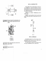
INSTALL REFLECTORS
~""
'0·
.
Your bicycle comes equipped with mounting reflector brackets .
Securely attach the front reflector (white) to the front mounting
bracket and the rear reflector (red) to the rear mounting bracket. Side
reflectors must be mounted within three inches of the inside to the rim.
,
~~C_
Figure 10
{:
:;
I
()pon
.::~
c_ ...,
So.. , -
INSTALL SADDLE
Loosen the seat clamp nut and position the seat clamp on the seat
post with the clamp forward of the seat bolt. For a seat post with a
built.in seat clamp, looSCln bolt and place the straight section of the seat
rails between the top and bottom plates. With the saddle in level
position, tighten the seat clamp nut/bolt so that saddle will not rotate
and will remain level.
Hul
"\
''''.Figure II
22
........
-c9J'"
Figure 12
23
INSTALL BRAKE LEVERS, SlUFf LEVERS, pRIPS
INSTALLAnON AND ADJUSTMENT OF BRAKES
Slide shift levers onto the handlebar so that the cables face towards
the stem of the handlebar. Install mounting nuts and bolts but do not
tighten. Install the brake levers the same way. Do not tighten yet.
WARNING: Always inspect the brakes before riding to be sure
they are functioning properly.
CAUTION: The lever for the rear brake must be mounted on the
right side of the handlebar and the lever for the front brake must be
mounted on the left side of the handlebar.
Slide the handlebar grips completely onto the hamilebar and install
the handlebar end plugs. if applicable, as far as they will go into th~
handlebar.
Slide the brake levers back to the handlebar grip. Rotate to find
the most convenient operating position and tighten the brake lever
damp securely.
Slide the shift lever(s) back to the brake levers. Rotate to find the
most convenient operating position and tighten the shift lever clamp(s)
securely.
NOTE: On some brake levers, the handlebar to lever distance car.
be adjusted by turning the reach adjuster bolt. Whenever this adjust·
ment is made, make sure to check the braking action and re·adjust
if necessary by following instructions in brake adjustment section.
Locknut
Adjusting Sarrel
\ I!
\
i
J-.--'
\!}
Figure
I.~
Expander Solt
WARNING: If you find it difficult to do the brake. fitting and
adjustment, it is recommended that the work be done by a qualified
bicycle mechanic. Do not attempt to ride the bicycle if brakes do not
function properly.
CANTILEVER BRAKES: Make sure the cantilever brazed-on
bosses on the frame or fork are clean and free of paint. Slide a brake
ann onto the boss; it must be able to spin freely on the boss. Remove
the brake arm. If the brake arm did not spin freely, clean the surfaces
with a fine emery cloth.
Apply a light grease1 to the ou tside surface of the boss. Do not get
any grease inside the threaded portion of the boss.
For the front brake, insert the straight end of the spring into the
hole in the boss, then mount the brake arms and engage the spring to
the brake arm for the right and left sides. Both of tpe rubber brake
shoes should be facing upwards. If they are not, switch the arms right
to left and left to right. Secure the brake arm in place by using the
washer (with serrations, if any, facing outward) and the mounting
bolt. If too much binding occurs during installation, remove the
mounting bolt and make sure the threaded area of the brazed-on boss
is free of debris.
Repeat the same procedure for the rear brakes.
CAUTION: Do not overtighten mounting bolts. This can cause
the stud to expand, impairing movement of the brake arms.
Position the brake shoes so that the rim face and the brake shoes
are aligned; (he top and bottom of the pac' should contact with the run
at the ·same time. If the rim face is deeper than the brake pad face.
the pad should contact the rim as high as possible without overlapping
the tire. Position the shoe so that when viewed from the top, the front
of the shoe strikes the rim slightly before the rear of the shoe. Secure
in place by using an allen wrench' to hold the brake shoe bolt in place
while tightening the nut. Tighten the nut securely at a torque of 6069 inch/pounds so that the brake shoe bolt cannot move.
Attach the straddle cable hanger to the 'straddle cable and insert
the brake cable into the hole in the cable anchor bolt in the straddle
cable hanger. Place the ends of the straddle cable into the ends of the
25
CANTILEVER BRAKE INSTALLATlON
brake arms.
Adjust the clearance between the rim and brake shoe by moving
the brake cable through the cable anchor bolt and tighten securely.
Flex the cable and housing while squeezing the brake lever to seat and
compress the cable housing. Make sure that the casing is properly seated
in all casing lugs, ferrules, adjusting barrels and levers. Readjust the
shoe clearance using the cable anchor bolt to eliminate any slack in
the cable. Make sure that the braking action is effective well before
the brake lever touches the grip. Minor adjustments for the brake shoe
to rim clearance can be made by using the adjusting barrels on the
brake levers. Be sure to lock the adjusting barrel in place by tightening
the locknut against the brake lever.
__s ~~
Spring Hole
Direction of Rotation
Brake Shoe
:CX~
~~~Ji
Rim
_ _ Brake Cable
~~,..--- Straddle Cable
Rear
~rake Shoe
Hanger
~ Brazed-on Boss
' - _ - - - Straddle Cable
,
\ Se",,,d W"",,,
Mounting Bolt
26
FIGURE 14
27
OPERAnON OF DERAILLEUR GEARS
Multiple gear ratios provide a means of maintaining a constant
pedaling rate, regardless of road level conditions. Mamtaining a constant pedaling rate is the most efficient cycling technique and is less
tiring over long distances than pedaling at varying rates and then
coasting.
The derailleurs are activated by cables connected to shift levers
located on the handlebar. Derailleurs work by moving the chain from
one sprocket to another. The left lever controls the front derailleur and.
the right lever controls the rear derailleur.
Change only one gear (front or rear) at a time. Continue pedaling,
with relaxed pressure, while moving shift levers to the gear position
that allows the pedaling pressure and rate you find most comfortable.
Shift only when pedals and wheels are m motion. Never back-pedal
while shifting gears. Never· force the shift levers.
Chain noise often results from changing gears. If chain noise
continues after shifting, move the appropriate shift lever slightly
backward Qf forward to fine adjust chain alignment and eliminate the
noise.
taut and retighten nut securely.
With the right shift lever all the way back, the rear derailleur
should position the chain on the largest rear sprocket. Adjust limiting
screw "L" to allow for this and position it to bottom against the derailleur housing to prevent any additional inward travel of the rear derail·
leur. This will stop the chain from running off the inside of the large
rear sprocket.
••
DERAJLLEUR ADJUSTMENTS
REAR DERAILLEUR: With the right shift lever all the way forward, the rear derailleur should position the chain on the smallest rear
sprocket. If the chain does not reach the smallest sprocket, adjust
limiting screw "H" (moving it out, away from the derailleur housing)
allowing the necessary additional outward travel of the derailleur.
Once adjusted, limiting screw "H" should be moved to bottom
against the derailleur housing, stopping any additional outward travel
of the derailleur and preventing the chain from running off the smallest
sprocket.
With the rear derailleur positioned so tnat the chain is on the
smallest sprocket (right shift lever all the way forward), there should
be no trace of slack in the control cable. Normally a few counterclockwise turns of the barrel adjustment, where applicable, will take
up most of all of the slack in the cable. Wit doesn't, a cable adjustment
is necessary. Note, some derailleurs do not have a barrel adjustment
and therefore require a cable adjustment. If a cable adjustment is
required, loosen cable anchor 'nut freeing the cable. Pull the cable
28
t
Cable
Adjusting Barre'
Cab/I! F ,xlOQ
Boll
Adjustin<;l Screw
Figure 15
29
FRONT DERAJLLEUR: The derailling cage must be posltmned
hith enough to clear the chain wheels while shifting If an adjustmen t
is necessary, loosen the frame clamp and reposition accordingly. When
retightening the frame clamp nut, make sure the curvature of derailling
cage is concentric to the curvature of the chainwheel and that the
derailling cage is in line with chainwheel.
Move left shift lever all the way forward and adjust limiting screw
"l" to center derailling cage and chain over the smaller chainwheel
againsl the derailleur housing.
Place left lever all the way back, centering derail ling cage and chain
over the large chainwheel and adjust screw "H"
These adjustments will limit the inward and outward movement of
the derailling cage so the chain will not derail to the left of the inside
chainwheel or to the right of the outside chainwhed.
loosen the cable anchor nut and pull all slack out of the cable
through the anchor bolt. Retighten the cable anchor nut securely.
CAUTION: Wing tension screws located on the shift levers should
be adjusted only tight enough to prevent any unwanted gear change
which can be caused by the spring tension of the derailleur.
Figure 16
SUNTOUR ACCUSHIFT DERAJLLEURS: Check axle placement
in the rear dropouts. "If the dropouts have horizontal slots, move the
rear axle as far forward as is safely possible. This moves the rear
derailleur's guide pulley closer to the freewheel.
Center the guide pulley directly unQer the smallest freewheel cog
by adjusting the rear derailleur's high gear limit screw (H). This adjust.
ment is critical: Accushift indexing is keyed to this centered guide
pulley position. After adjusting the high gear limit screw, adjust the
low gear limit screw (l) so that the guide pulley centers directly under
the largest freewheel cog.
After cable installation, push the shift lever a few times to remove
initial cable slack. Then retighten cable.
Confirm that the chain is the correct length by shifting in 10 highest
gear (smallest. freewheel cog and largest chainring). Then, while holding
the rear derailleur body parallel to the chainstay, locate the small dot
on the pulley cage (on the Alpha 3000, the rear derailleur uses the cage
pivot stop pin as reference instead of a dot). If the chain is the correct
length, then the dot will line up with specif1c reference marks on the
main body of the rear derailleur.
Turn the angle adjusting screw counterclockwise as far as possible.
This rotates the rear derailleur forward, pUlling it even closer to the
freewheel and optimizing guide pulley placement. If the guide pulley
is too close to the freewheel, it will not be able to shift the chain off
the largest freewheel cog. If you notice this, turn the angle adJustlDg
screw clockwise to move the rear derailleur back. Adjust until the
chain shifts off the largest cog. In most cases, the angle adjusting
screw can remain all the way out.
In order to fine tune for perfe~t shifting performance, start with
the largest freewheel cog and shift to the next smallest cog. Adjust
cable tension at cable adjusting barrel if required. Continue through
all cogs,. then shift up to ensure adjustments. If necessary, you can
easily turn the cable adjusting barrel by pushing the shift lever back
to loosen cable tension. Make sure the guide pulley aligns with each
cog during this process.
With the chain on any freewheel cog (except the innermost) and
the shift lever in "Index" mode, move the lever slightly, taking up the
small amount of free movement designed into the system. The ~ear
derailleur must move a corresponding amount. If it does not, there is
a cable binding problem. The source of the drag must be located and
eliminated. Be sure all cable routes are free of dirt, grit, filings and
grime. If necessary, clean and grease the cable guide under the bottom
bracket.
3\
BEARING ADJUSTMENTS
There are four places on the bicycle that contain bearings that may
require adjustment: the headset. front hub. crankset and rear hub.
HEADSET BEARINGS: To check bearing adjustment, lift up
handlebar at the grips. There should be no play of the handlebar stem
and fork. but the handlebar must be able to turn freely and easily.
To adjust. remove head lock nut ~n.d reflector bracket. Turn the
adjusti'ng cone clockwise until fingertight. Replace reflector brackel
and tighten head lock nut setting the adjustment.
HUB BEARINGS: To check bearring adjustment. hold the wheel
bearings checked off the ground and try rotating it. The wheel bearings
adjustment must be set so that the wheel can turn easily and freely
with only a trace of side play at the wheel rim
To adjust. remove the wheel arid loosen locknut on one side of the
wheel while holding the adjusting cone on the same side of the hub
with a flat open-end wrench and rotate the adjusting cone as needed
to eliminate side play. Tighten the locknut while holding the adjusting
cone in the desired position.
CRANK. BEARINGS: To check bearing adjustment. hold one end
of the crank and trying to move it sideways. There should only be
a trace of play. The crank bearing adjustment must be set so that the
crank can tum easily and freely.
To adjust. remove the Jockring and loosen or tighten adjusting cup
at left side. Check proper rotation and side play. Reset lockring and
tighten.
TIRE CARE AND WHEEL ADJUSTMENT
Keep tires inflated to the pressure indicated on the sidewall of the
tire. Use hand or foot pump to inflate the tire. Improper tire pressure
will cause excessive wear, causing premature replacement. Blowouts
are the result of overinflation or may be caused by the tire not being
properly on the rim when inflated.
Whenever you hear any irregular noise from the wheels or the
brakes touch to the rim. the wheels should be checked and repaired.
If there is minor loosening of the spokes. you may tighten the nipples.
but it is recommended that you take the bicycle to a bicycle mechanic
Wheels should be checked regularly for spoke tightness and true align·
ment.
Montague CorporatIon
P.O. Box 381118
Cambridge, MA 02238
32
\
U.S.A.