1
MC40
INTEGRATOR GUIDE
MC40 INTEGRATOR GUIDE
72E-166943-02
Rev. A
April 2013
ii
MC40 Integrator Guide
No part of this publication may be reproduced or used in any form, or by any electrical or mechanical means,
without permission in writing from Motorola. This includes electronic or mechanical means, such as
photocopying, recording, or information storage and retrieval systems. The material in this manual is subject to
change without notice.
The software is provided strictly on an “as is” basis. All software, including firmware, furnished to the user is on
a licensed basis. Motorola grants to the user a non-transferable and non-exclusive license to use each
software or firmware program delivered hereunder (licensed program). Except as noted below, such license
may not be assigned, sublicensed, or otherwise transferred by the user without prior written consent of
Motorola. No right to copy a licensed program in whole or in part is granted, except as permitted under
copyright law. The user shall not modify, merge, or incorporate any form or portion of a licensed program with
other program material, create a derivative work from a licensed program, or use a licensed program in a
network without written permission from Motorola. The user agrees to maintain Motorola’s copyright notice on
the licensed programs delivered hereunder, and to include the same on any authorized copies it makes, in
whole or in part. The user agrees not to decompile, disassemble, decode, or reverse engineer any licensed
program delivered to the user or any portion thereof.
Motorola reserves the right to make changes to any software or product to improve reliability, function, or
design.
Motorola does not assume any product liability arising out of, or in connection with, the application or use of
any product, circuit, or application described herein.
No license is granted, either expressly or by implication, estoppel, or otherwise under any Motorola, Inc.,
intellectual property rights. An implied license only exists for equipment, circuits, and subsystems contained in
Motorola products.
iii
Revision History
Changes to the original guide are listed below:
Change
Date
Description
-01 Rev A
11/30/12
Initial release.
-02 Rev A
04/26/13
Add Rev 2 software and VoIP telephony support.
iv
MC40 Integrator Guide
TABLE OF CONTENTS
About This Guide
Introduction .....................................................................................................................................
Documentation Set ...................................................................................................................
Configurations.................................................................................................................................
Versions ..........................................................................................................................................
Chapter Descriptions ......................................................................................................................
Notational Conventions...................................................................................................................
Related Documents ........................................................................................................................
Service Information .........................................................................................................................
xi
xi
xi
xii
xii
xii
xiii
xiii
Chapter 1: Getting Started
Introduction ....................................................................................................................................
Unpacking the MC40 .....................................................................................................................
Getting Started ...............................................................................................................................
Installing the Battery ................................................................................................................
Charging the Battery ................................................................................................................
Charging the Main Battery .................................................................................................
Charging Temperature .......................................................................................................
Charging Spare Batteries ...................................................................................................
Powering On the MC40 ............................................................................................................
Powering Off the MC40 ............................................................................................................
Replacing the Battery .....................................................................................................................
Resetting the MC40 .......................................................................................................................
Soft Reset ................................................................................................................................
Hard Reset ...............................................................................................................................
Enterprise Reset ......................................................................................................................
Factory Reset ...........................................................................................................................
Waking the MC40 ..........................................................................................................................
1-1
1-1
1-1
1-2
1-2
1-2
1-3
1-3
1-3
1-4
1-4
1-4
1-5
1-5
1-5
1-6
1-7
Chapter 2: Accessories
Introduction .................................................................................................................................... 2-1
Single Slot USB Docking Cradle .................................................................................................... 2-3
vi
MC40 Integrator Guide
Setup ........................................................................................................................................
Charging the MC40 Battery .....................................................................................................
Four Slot Charge Only Docking Cradle .........................................................................................
Setup ........................................................................................................................................
Four Slot Battery Charger ..............................................................................................................
Setup ........................................................................................................................................
USB/Charge Cable ........................................................................................................................
Charging the MC40 Battery .....................................................................................................
2-way Charge Cable ......................................................................................................................
Handstrap ......................................................................................................................................
CS3070 Bluetooth Scanner ...........................................................................................................
Bluetooth Connection ...............................................................................................................
Human Interface Device Emulation ...................................................................................
Options ...............................................................................................................................
HID Pairing ...............................................................................................................................
Numeric Bar Codes for PIN Entry ............................................................................................
Configuring the Scanner ..........................................................................................................
Replacement Bezel ........................................................................................................................
2-3
2-3
2-5
2-5
2-7
2-7
2-9
2-9
2-10
2-11
2-14
2-14
2-14
2-14
2-14
2-16
2-16
2-17
Chapter 3: USB Communication
Connecting to a Host Computer via USB ...................................................................................... 3-1
Disconnect from the Host Computer ........................................................................................ 3-2
Chapter 4: DataWedge Configuration
Introduction ....................................................................................................................................
Basic Scanning ..............................................................................................................................
Profiles ...........................................................................................................................................
Profile0 .....................................................................................................................................
Plug-ins ..........................................................................................................................................
Input Plug-ins ...........................................................................................................................
Bar Code Scanner Input Plug-in ........................................................................................
Process Plug-ins ......................................................................................................................
Basic Data Formatting Process Plug-in .............................................................................
Output Plug-ins ........................................................................................................................
Keystroke Output Plug-in ...................................................................................................
Intent Output Plug-in ..........................................................................................................
Profiles Screen ..............................................................................................................................
Profile Context Menu .........................................................................................................
Options Menu .....................................................................................................................
Disabling DataWedge ..............................................................................................................
Create a New Profile ......................................................................................................................
Configuring a Profile ......................................................................................................................
Applications ..............................................................................................................................
Associated Apps ................................................................................................................
Barcode Input ...........................................................................................................................
Enabled ..............................................................................................................................
Decoders ............................................................................................................................
Decoder Params ................................................................................................................
UPC EAN Params ..............................................................................................................
4-1
4-1
4-2
4-2
4-2
4-3
4-3
4-3
4-3
4-3
4-3
4-3
4-3
4-4
4-4
4-5
4-5
4-6
4-6
4-6
4-7
4-7
4-8
4-8
4-13
Table of Contents
Reader Params ..................................................................................................................
Scan Params ......................................................................................................................
Keystroke Output .....................................................................................................................
Intent Output ............................................................................................................................
Intent Overview ..................................................................................................................
DataWedge Settings ......................................................................................................................
Import Configuration File ..........................................................................................................
Export Configuration File .........................................................................................................
Restore DataWedge ................................................................................................................
Configuration File Management .....................................................................................................
Enterprise Folder .....................................................................................................................
Auto Import ..............................................................................................................................
Programming Notes .......................................................................................................................
Remap Keys ............................................................................................................................
Overriding Trigger Key in an Application .................................................................................
Capture Data and Taking a Photo in the Same Application .....................................................
Disable DataWedge on MC40 and Mass Deploy .....................................................................
4-14
4-15
4-15
4-16
4-16
4-17
4-18
4-18
4-18
4-19
4-19
4-19
4-19
4-19
4-20
4-20
4-20
Chapter 5: WLAN Configuration
Introduction ....................................................................................................................................
Configure a Wi-Fi Network .............................................................................................................
Manually Adding a Wi-Fi Network ..................................................................................................
Advanced Wi-Fi Settings ................................................................................................................
Proxy Configuration .................................................................................................................
Remove a Wi-Fi Network ...............................................................................................................
Static IP Address ...........................................................................................................................
5-1
5-1
5-3
5-3
5-4
5-5
5-5
Chapter 6: Administrator Utilities
Introduction ....................................................................................................................................
Required Software ...................................................................................................................
On-device Application Installation ............................................................................................
Multi-user/AppLock Configuration ..................................................................................................
Enterprise Administrator Application ..............................................................................................
Create Users ............................................................................................................................
Add Packages ..........................................................................................................................
Create Groups .........................................................................................................................
Save Data ................................................................................................................................
Export Files ..............................................................................................................................
Import User List ........................................................................................................................
Import Group List .....................................................................................................................
Edit a User ...............................................................................................................................
Delete a User ...........................................................................................................................
Edit a Group .............................................................................................................................
Delete a Group .........................................................................................................................
Edit a Package .........................................................................................................................
Delete a Package .....................................................................................................................
MultiUser Administrator ..................................................................................................................
Disable the Multi-user Feature .................................................................................................
Capturing a Log File .................................................................................................................
6-1
6-1
6-1
6-2
6-2
6-2
6-3
6-4
6-4
6-4
6-5
6-5
6-5
6-5
6-5
6-6
6-6
6-6
6-6
6-7
6-7
vii
viii
MC40 Integrator Guide
AppLock Administrator ...................................................................................................................
Manual File Configuration ..............................................................................................................
Groups File ..............................................................................................................................
White List File ..........................................................................................................................
Determining Applications Installed on the MC40 .....................................................................
Secure Storage ..............................................................................................................................
Installing a Key .........................................................................................................................
Viewing Key List .......................................................................................................................
Delete a Key ............................................................................................................................
Volumes ...................................................................................................................................
Create Volume Using EFS File ..........................................................................................
Create Volume Manually ....................................................................................................
Mount Volume ....................................................................................................................
List Volumes ......................................................................................................................
Unmount Volume ...............................................................................................................
Delete Volume ...................................................................................................................
Create EFS File .......................................................................................................................
Off-line Extraction Tool ............................................................................................................
Usage .................................................................................................................................
Creating an Image .............................................................................................................
Mounting an Image ............................................................................................................
Unmounting an Image ........................................................................................................
6-8
6-8
6-8
6-9
6-10
6-10
6-10
6-11
6-11
6-12
6-12
6-12
6-13
6-13
6-13
6-14
6-14
6-14
6-14
6-15
6-16
6-16
Chapter 7: Settings
Introduction ....................................................................................................................................
Location Settings ...........................................................................................................................
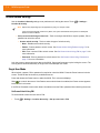
Screen Unlock Settings .................................................................................................................
Single User Mode ....................................................................................................................
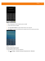
Set Screen Unlock Using PIN ............................................................................................
Set Screen Unlock Using Password ..................................................................................
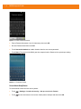
Screen Unlock Using Pattern .............................................................................................
Removing or Change the Screen Lock ..............................................................................
Multiple User Mode ..................................................................................................................
Passwords .....................................................................................................................................
Button Remapping .........................................................................................................................
Exporting a Configuration File ..................................................................................................
Importing a Configuration File ..................................................................................................
Creating Remap File ................................................................................................................
Enterprise Reset ......................................................................................................................
Accounts & Sync Settings ..............................................................................................................
Language Usage ...........................................................................................................................
Keyboard Settings .........................................................................................................................
About Device .................................................................................................................................
7-1
7-1
7-2
7-2
7-2
7-3
7-4
7-5
7-5
7-5
7-5
7-6
7-6
7-7
7-7
7-7
7-7
7-8
7-8
Chapter 8: Application Deployment
Introduction ....................................................................................................................................
Security ..........................................................................................................................................
Secure Certificates ...................................................................................................................
Credential Storage Settings .....................................................................................................
8-1
8-1
8-1
8-2
Table of Contents
Development Tools ........................................................................................................................
Development Settings ..............................................................................................................
ADB USB Setup .............................................................................................................................
Windows XP and Windows 7 Installation .................................................................................
Linux Installation ......................................................................................................................
Application Installation ...................................................................................................................
Installation Using USB Connection ..........................................................................................
Using Android Debug Bridge ...................................................................................................
Mobility Services Platform ........................................................................................................
Uninstall an Application ............................................................................................................
System Update ..............................................................................................................................
Storage ..........................................................................................................................................
Random Access Memory .........................................................................................................
External Storage ......................................................................................................................
Internal Storage .......................................................................................................................
Enterprise Folder .....................................................................................................................
Managing Applications ...................................................................................................................
Get Details About an Application .............................................................................................
Stopping an Application ...........................................................................................................
Changing Application Location ......................................................................................................
Managing Downloads ....................................................................................................................
Chapter 9: Maintenance & Troubleshooting
Introduction ....................................................................................................................................
Maintaining the MC40 ....................................................................................................................
Battery Safety Guidelines ..............................................................................................................
Cleaning .........................................................................................................................................
Approved Cleanser Active Ingredients .....................................................................................
Harmful Ingredients ..................................................................................................................
Cleaning Instructions ...............................................................................................................
Special Cleaning Notes ............................................................................................................
Materials Required ...................................................................................................................
Cleaning the MC40 ..................................................................................................................
Housing ..............................................................................................................................
Display ...............................................................................................................................
Camera Lens ......................................................................................................................
Connector ...........................................................................................................................
Cleaning Cradle Connectors ....................................................................................................
Cleaning Frequency .................................................................................................................
Troubleshooting .............................................................................................................................
MC40 .......................................................................................................................................
Single Slot USB Docking Cradle ..............................................................................................
Four Slot Charge Only Docking Cradle ....................................................................................
Four Slot Spare Battery Charger .............................................................................................
USB/Charge Cable ..................................................................................................................
8-2
8-3
8-3
8-3
8-4
8-4
8-5
8-5
8-6
8-6
8-7
8-8
8-8
8-9
8-10
8-10
8-11
8-11
8-12
8-12
8-13
9-1
9-1
9-1
9-2
9-2
9-3
9-3
9-3
9-3
9-3
9-3
9-3
9-3
9-3
9-4
9-4
9-5
9-5
9-7
9-7
9-8
9-8
Appendix A: Technical Specifications
MC40 Technical Specifications ...................................................................................................... A-1
Connector Pin-outs ........................................................................................................................ A-3
ix
x
MC40 Integrator Guide
I/O Connector Pin-Outs ............................................................................................................
HDMI Connector Pin-outs ........................................................................................................
Headset Connector ..................................................................................................................
Expansion Module Connector Pin-outs ....................................................................................
MC40 Accessory Specifications ....................................................................................................
Single Slot USB Docking Cradle ..............................................................................................
Four Slot Battery Charger ........................................................................................................
Four Slot Charge Only Docking Cradle ....................................................................................
USB/Charge Cable ..................................................................................................................
2-way Charge Cable ................................................................................................................
A-3
A-4
A-6
A-6
A-8
A-8
A-8
A-9
A-9
A-10
Appendix B: Keypad Remap Strings
Introduction .................................................................................................................................... B-1
Glossary
Index
ABOUT THIS GUIDE
Introduction
This guide provides information about using the MC40 and accessories.
NOTE Screens and windows pictured in this guide are samples and can differ from actual screens.
Documentation Set
The documentation set for the MC40 provides information for specific user needs, and includes:
• MC40 Quick Start Guide - describes how to get the MC40 up and running.
• MC40 User Guide - describes how to use the MC40.
• MC40 Integrator Guide - describes how to set up the MC40 and accessories.
Configurations
This guide covers the following configurations:
Configuration
MC40N0
Radios
WLAN: 802.11a/b/g/n
WPAN: Bluetooth v2.1
with EDR
Display
Memory
Data Capture
Options
4.3” WVGA
Color
1 GB RAM /
8 GB Flash
camera and
imager or
camera, imager
and MSR with
encryption
capability*
* Contact Motorola Solutions for more information.
Operating
System
Android based,
Android
Open-Source
Project 2.3
xii
MC40 Integrator Guide
Versions
To determine the current hardware and software versions touch
> Settings > About device.
• Serial number - Displays the serial number.
• Model number - Displays the model number.
• Android version - Displays the operating system version.
• Kernel version - Displays the kernel number.
• Build number - Displays the software build number.
The build number contains the software revision number and whether the MC40 is VoIP telephony ready.
Example Build Number: 0x-271301-G-1200-0014-y0-M1-mmddyy
• x = software revision number
• y = VoIP telephony ready
where:
• 0 = not VoIP telephony ready
• V = VoIP telephony ready.
Chapter Descriptions
Topics covered in this guide are as follows:
• Chapter 1, Getting Started provides information on getting the MC40 up and running for the first time.
• Chapter 2, Accessories describes the available accessories and how to use them with the MC40.
• Chapter 3, USB Communication describes how to connect the MC40 to a host computer using USB.
• Chapter 4, DataWedge Configuration describes how to use and configure the DataWedge application.
• Chapter 5, WLAN Configuration describes the available accessories and how to use them with the
MC40.
• Chapter 6, Administrator Utilities provides information for using the suite of administrative tools for
configuring the MC40.
• Chapter 7, Settings describes the settings for configuring the MC40.
• Chapter 8, Application Deployment explains Bluetooth functionality on the MC40.
• Chapter 9, Maintenance & Troubleshooting includes instructions on cleaning and storing the MC40, and
provides troubleshooting solutions for potential problems during MC40 operation.
• Appendix A, Technical Specifications provides the technical specifications for the MC40.
• Appendix B, Keypad Remap Strings provides a list of keypad remap strings.
About This Guide
Notational Conventions
The following conventions are used in this document:
• Italics are used to highlight the following:
• Chapters and sections in this and related documents
• Icons on a screen.
• Bold text is used to highlight the following:
• Dialog box, window, and screen names
• Drop-down list and list box names
• Check box and radio button names
• Key names on a keypad
• Button names on a screen.
• bullets (•) indicate:
• Action items
• Lists of alternatives
• Lists of required steps that are not necessarily sequential
• Sequential lists (e.g., those that describe step-by-step procedures) appear as numbered lists.
Related Documents
• MC40 Quick Start Guide, p/n 72-167493-xx.
• MC40 Regulatory Guide, p/n 72-166942-xx.
• MC40 User Guide, p/n 72E-166940-xx.
• MSP Client Software Guide, p/n 72E-128805-xx
For the latest version of this guide and all guides, go to: http://supportcentral.motorola.com
Service Information
If you have a problem with your equipment, contact Motorola Solutions support for your region. Contact
information is available at: http://www.motorolasolutions.com/support.
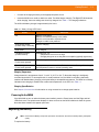
When contacting Motorola Solutions Global Customer Support, please have the following information
available:
• Serial number of the unit (found on manufacturing label)
• Model number or product name (found on manufacturing label)
• Software type and version number
xiii
xiv
MC40 Integrator Guide
Manufacturing label
Motorola Solutions responds to calls by email or telephone within the time limits set forth in support
agreements.
If your problem cannot be solved by Motorola Solutions Support, you may need to return your equipment for
servicing and will be given specific directions. Motorola Solutions is not responsible for any damages incurred
during shipment if the approved shipping container is not used. Shipping the units improperly can possibly void
the warranty.
If you purchased your Motorola Solutions business product from a Motorola business partner, contact that
business partner for support.
CHAPTER 1
GETTING STARTED
Introduction
This chapter provides information about the MC40, accessories, charging, and resetting the MC40.
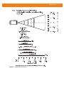
Unpacking the MC40
Carefully remove all protective material from the MC40 and save the shipping container for later storage and
shipping. Verify that you received the following equipment:
• MC40
• Lithium-ion battery
• Regulatory Guide
• Quick Start Guide.
Inspect the equipment. If any equipment is missing or damaged, contact the Motorola Solutions Global
Customer Support immediately. See Service Information on page xiii for contact information.
Prior to using the MC40 for the first time, remove the protective shipping film that covers the scan window,
display and camera window.
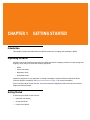
Getting Started
To start using the MC40 for the first time:
1.
Install the main battery.
2.
Charge the MC40.
3.
Power on the MC40.
1-2
MC40 Integrator Guide
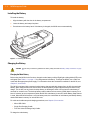
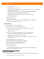
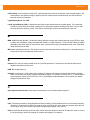
Installing the Battery
To install the battery:
1.
Align the battery with the slots in the battery compartment.
2.
Lower the battery and snaps into place.
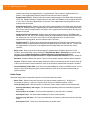
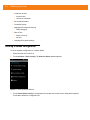
3.
Press down on the battery latch. If the battery is charged, the MC40 turns on automatically.
Figure 1-1 Inserting the Battery
Charging the Battery
CAUTION
Ensure that you follow the guidelines for battery safety described in Battery Safety Guidelines on page
9-1.
Charging the Main Battery
Before using the MC40 for the first time, charge the main battery until the Right light emitting diode (LED) turns
solid green (see Table 1-1 on page 1-3 for charge status indications). To charge the MC40, use a cable or a
cradle with the appropriate power supply. For information about the accessories available for the MC40, see
Chapter 2, Accessories.
The MC40 is equipped with a memory backup battery that automatically charges from the fully-charged main
battery. When using the MC40 for the first time, the backup battery requires approximately 36 hours to fully
charge. This is also true any time the backup battery is discharged, which occurs when the main battery is
removed for several hours. The backup battery retains random access memory (RAM) data in memory for at
least 10 minutes (at room temperature) when the MC40’s main battery is removed, when Battery Swap feature
is used. When the MC40 reaches a very low battery state, the combination of main battery and backup battery
retains RAM data in memory for at least 48 hours.
For cable and cradle setup and charging procedures, see Chapter 2, Accessories.
• Micro USB Cable
• Single Slot Charging Cradle
• Five Slot Universal Charge Only Cradle.
To charge the main battery:
Getting Started
1-3
1.
Connect the charging accessory to the appropriate power source.
2.
Insert the MC40 into a cradle or attach to a cable. The MC40 begins charging. The Right LED blinks amber
while charging, then turns solid green when fully charged. See Table 1-1 for charging indications.
The 2680 mAh battery charges in approximately four hours.
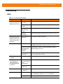
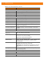
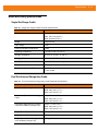
Table 1-1 Battery Charge LED Status
Status
Indication
Off
MC40 is not charging.
MC40 is not inserted correctly in the cradle.
MC40 is not connected to a power source.
Charger or cradle is not powered.
Slow Blinking Amber
(3 blinks every 2 seconds)
MC40 is charging.
Solid Green
Fully charged.
Fast Blinking Amber
(3 blinks/second)
Charging error, e.g.:
• Temperature is too low or too high.
• Charging has gone on too long without completion (typically eight hours).
Flashes Amber once when
Power button pressed
Critical battery level. Battery too low to boot device.
Fast blinking Amber when
Power button pressed
Battery over-temperature condition. Device shuts down. Battery will not charge
until temperature returns to normal operating value.
Charging Temperature
Charge batteries in temperatures from 0 °C to 40 °C (32 °F to 104 °F). Note that charging is intelligently
controlled by the MC40. To accomplish this, for small periods of time, the MC40 or accessory alternately
enables and disables battery charging to keep the battery at acceptable temperatures. The MC40 or accessory
indicates when charging is disabled due to abnormal temperatures via its LED. See Table 1-1.
Charging Spare Batteries
See Chapter 2, Accessories for information on using accessories to change spare batteries.
Powering On the MC40
If the MC40 did not turn on when the battery was installed, press the Power button until the Right and Left
LEDs flash once. The splash screen displays for about a minute as the MC40 initializes its flash file system.
Note that these windows also appear upon reset.
Replacing the Battery
NOTE Ensure that the Battery Swap mode procedures are followed, otherwise the backup battery will deplete
quickly.
To replace the battery:
1-4
MC40 Integrator Guide
1.
Press the Power button until the Device options menu displays.
2.
Touch Battery swap. The Right and Left LEDs light red.
3.
Wait until the LEDs turns off.
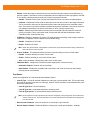
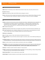
4.
Lift the battery latch.
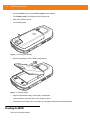
Figure 1-2 Removing the Battery
5.
Remove the battery out of the battery compartment.
Figure 1-3 Remove Battery
6.
Align the replacement battery in the battery compartment.
7.
Lower the battery and press down until it snaps into place.
8.
Press down on the battery latch. If the battery is charged, the MC40 turns on automatically.
Resetting the MC40
There are four reset functions:
Getting Started
1-5
• Soft Reset
• Hard Reset
• Enterprise Reset
• Factory Reset.
Soft Reset
Perform a Soft Reset when applications become unresponsive.
To perform a Soft Reset:
1.
Press and hold the Power button until the Device options menu appears.
2.
Touch Reset.
Hard Reset
Perform a Hard Reset when the MC40 stops functioning. To perform a Hard Reset simultaneously press and
release the Left Scan/Action, Volume Up and Power buttons.
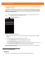
Enterprise Reset
An Enterprise Reset erases all data in the /cache and /data partitions and clears all MC40 settings, except
those in the /enterprise partition.
To perform an Enterprise Reset:
1.
Download the Enterprise Reset file from Motorola Support Central web site.
2.
Copy the 40N0GxxERxxxxxxx.zip file to the root directory of the On-device Storage. See Chapter 3, USB
Communication.
3.
Press and hold the Power button until the Device options menu appears.
4.
Touch Reset.
5.
Touch OK. The MC40 resets.
6.
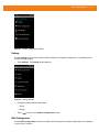
Press and hold the Left Scan/Action button.
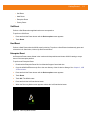
7.
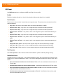
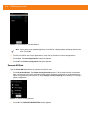
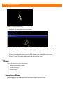
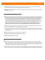
When the Recovery Mode screen appears release the Left Scan/Action button.
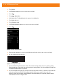
Figure 1-4 Recovery Mode Screen
1-6
MC40 Integrator Guide
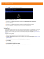
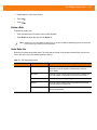
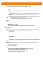
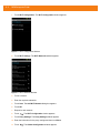
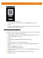
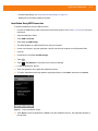
8.
Touch
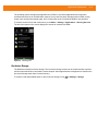
. The System Recovery screen appears.
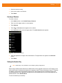
Figure 1-5 System Recovery Screen
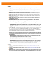
9.
Press the Up and Down volume buttons to navigate to the apply update from /sdcard option.
10. Press the PTT button.
11. Press the Up and Down volume buttons to navigate to the 40N0GxxERxxxxxxx.zip file.
12. Press the PTT button. The Enterprise Reset occurs and then the MC40 resets.
Factory Reset
A Factory Reset erases all data in the /cache, /data and /enterprise partitions in internal storage and clears all
MC40 device settings. A Factory Reset returns the MC40 to the last installed operating system image. To
revert to a previous operating system version, re-install that operating system image. See System Update on
page 8-7.
To perform a Factory Reset:
1.
Download the Factory Reset file from Motorola Support Central web site.
2.
Copy the 40N0GxxFRxxxxxxx.zip file to the root directory of the On-device Storage. See Chapter 3, USB
Communication.
3.
Press and hold the Power button until the Device options menu appears.
4.
Touch Reset.
5.
Touch OK. The MC40 resets.
6.
Press and hold the Left Scan/Action button.
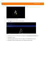
7.
When the Recovery Mode screen appears release the Left Scan/Action button.
Getting Started
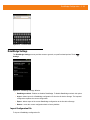
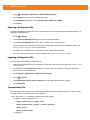
Figure 1-6 Recovery Mode Screen
8.
Touch
. The System Recovery screen appears.
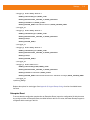
Figure 1-7 System Recovery Screen
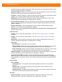
9.
Press the Up and Down volume buttons to navigate to the apply update from /sdcard option.
10. Press the PTT button.
11. Press the Up and Down volume buttons to navigate to the 40N0GxxFRxxxxxxx.zip file.
12. Press the PTT button. The Factory Reset occurs and then the MC40 resets.
1-7
1-8
MC40 Integrator Guide
CHAPTER 2
ACCESSORIES
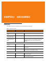
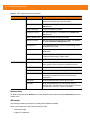
Introduction
This chapter provides set up information for the following MC40 accessories.
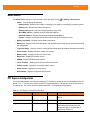
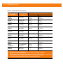
Table 2-1 MC40 Accessories
Accessory
Part Number
Description
Cradles
Single Slot Charge Only
Cradle
CRDMC40XX-1000R
Charges the MC40.
Five Slot Universal
Charge Only Cradle
CRDUNIV-40-5000R
Provides charging for up to five MC40 devices.
Five Slot Universal
Charge Only Cradle
Base
CRDUNIV-XX-5000R
Provides charging for up to five MC40 devices or four
MC40 device and one Four Slot Battery Charger using
optional Charging Cups. Requires separate power
supplies.
Four Slot Battery
Charger
SACMC40XX-4000R
Charges up to four MC40 batteries.
Power Supply
PWRS-124306-01R
Provides power to the MC40 and Single Slot Charge
Only Cradle.
Power Supply
PWRS-14000-148C
Provides power to the Five Slot Universal Charge Only
Cradle and the Four Slot Battery Charger.
Micro USB Cable
25-MCXUSB-01R
Provides power to the MC40 and USB communication
with a host computer.
2-way DC Cable
25-122026-02R
Connects one power supply (PWRS-14000-148C) to two
Four Slot Battery Chargers.
Chargers
Cables
2-2
MC40 Integrator Guide
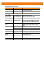
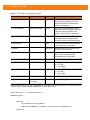
Table 2-1 MC40 Accessories (Continued)
Accessory
Part Number
Description
4-way DC Cable
25-85992-01R
Connects one power supply (PWRS-14000-241R) to
four Four Slot Battery Chargers.
US AC Line Cord
(3-wire)
23844-00-00R
Provides power to the power supplies.
Spare 2680 mAh
lithium-ion battery
BTRY-MC40EAB0E-01R
BTRY-MC40EAB0E-10R
Replacement 2680 mAh battery.
Replacement 2680 mAh battery (10-pack)
Charging Cup
CUPMC40XX-1000R
Mounts onto the Multi Slot Universal Charge Only Cradle
Base and provides MC40 charging slot (Single pack).
Battery Charger Cup
CUPUNIBTRY-1000R
Mounts on the Multi Slot Universal Charge Only Cradle
Base and provides mounting for the Four Slot battery
charger.
Universal Blank Slot
Cover
CUPUNICVR-5000R
Mounts on the onto the Five Slot Universal Charge Only
Cradle and covers a slot when a cup is not required.
(5-pack).
Protective Rubber Boot
SG-MC40-RBOOT-10R
Provides additional protection for the MC40.
SG-MC40-MBOOT-10R
Provides additional protection for the MC40 with MSR.
Soft Hip Holster
SG-MC40HLSTR-01R
Mounts on a belt and provides storage for the MC40.
Finger Strap
SG-MC40STRAP-01R
SG-MC40STRAP-10R
Mounts on the back of the MC40 and provides secure
option for holding the device (Single pack or 10-pack).
Rack/Wall Mount
Bracket
KT-UNIVLBRKT-01R
Provides for mounting the Five Slot Charge Only Cradle
onto a standard rack or wall.
Rack/Wall Shelf
KT-UNIVLSHLF-01R
Mounts on the Rack/Wall Mount Bracket. For use when
more than two power supplies are required.
Mono Corded Headset
21-SB1X-HDSET2-01R
Use for PTT communications.
Miscellaneous
Accessories
2-3
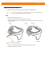
Single Slot Charge Only Cradle
The Single Slot Charge Only Cradle provides power for operating and charging the MC40.
NOTE Do not connect the micro USB cable from the Single Slot Charge cradle to a host computer USB port. The
cradle cannot charge the MC40 if connected to a host computer.
Setup
To setup the Single Slot Charge Only cradle:
1.
Plug the micro USB connector into the microUSB port on the cradle.
2.
Route the micro USB end of the Micro USB Cable through the Cable Channel and exit either to the front or
back of the cradle.
USB Port
USB Cable
USB Port
USB Cable
Cable Channel
Figure 2-1 Micro USB Cable Installation
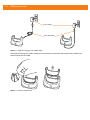
3.
Plug the other end of the Micro USB Cable into the USB port on the power supply.
4.
Plug the power supply into a wall outlet.
Cable Channel
2-4
MC40 Integrator Guide
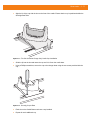
Power Supply
Micro USB Cable
Figure 2-2 Single Slot Charge Only Cradle Setup
The Single Slot Charge only cradle contains an insert that can be removed so that an MC40 with a rubber boot
can be inserted into the cradle.
Figure 2-3 Remove Cradle Insert
Accessories
2-5
Charging
To charge the MC40 battery, place the MC40 into the cradle.
Right LED
Figure 2-4 MC40 Battery Charging
The Right LED indicates the status of the battery charging. See Table 1-1 on page 1-3 for charging status
indications. The 2680 mAh battery charges in approximately four hours.
Charge batteries in temperatures from 0 °C to 40 °C (32 °F to 104 °F). Charging is intelligently controlled by the
MC40. To accomplish this, for small periods of time, the MC40 or accessory alternately enables and disables
battery charging to keep the battery at acceptable temperatures. The MC40 indicates when charging is
disabled due to abnormal temperatures via the Battery Charge LED. See Table 1-1 on page 1-3.
2-6
MC40 Integrator Guide
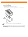
Four Slot Battery Charger
The Four Slot Battery Charger charges up to four MC40 spare batteries.
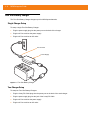
Single Charger Setup
To setup a single Four Slot Battery Charger:
1.
Plug the power supply plug into the power port on the back of the charger.
2.
Plug the AC line cord into the power supply.
3.
Plug the AC line cord into an AC outlet.
AC Line Cord
Power Supply
Figure 2-5 Four Slot Battery Charger
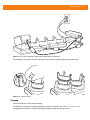
Two Charger Setup
To setup two Four Slot Battery Chargers:
1.
Plug the 2-way DC Cable plugs into the power port on the back of the each charger.
2.
Plug the power supply plug into the jack of the 2-way DC Cable.
3.
Plug the AC line cord into the power supply.
4.
Plug the AC line cord into an AC outlet.
Accessories
AC Line Cord
Power Supply
2-way DC Cable
Figure 2-6 Setup with 2-way DC Cable
Four Charger Setup
To setup four Four Slot Battery Charger:
1.
Plug the 4-way DC Cable plugs into the power port on the back of the each charger.
2.
Plug the 4-way DC Cable connector into the power output of the power supply.
3.
Plug the AC line cord into the power supply.
4.
Plug the AC line cord into an AC outlet.
2-7
2-8
MC40 Integrator Guide
AC Line Cord
Power Supply
4-way DC Cable
Figure 2-7 Setup with 4-way DC Cable
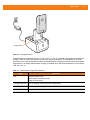
Charging
To charge the spare batteries:
1.
Insert the spare battery into a spare battery charging well.
A Charge LED is provided for each battery charging well. See Table 2-2 for charging status indications. The
2680 mAh battery charges in approximately four hours.
Accessories
2-9
Charge LEDs
Figure 2-8 Charging Batteries
Charge batteries in temperatures from 0 °C to 40 °C (32 °F to 104 °F). Charging is intelligently controlled by the
charger in order to ensure safe operation and optimize long-term battery life. To accomplish this, for small
periods of time, the charger alternately enables and disables battery charging to keep the battery at acceptable
temperatures. The charger indicates when charging is disabled due to abnormal temperatures via the Charge
LED. See Table 2-2.
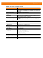
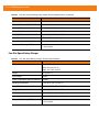
Table 2-2
Spare Battery Charge LED Indicators
LED
Indication
Off
No spare battery in slot.
Spare battery not placed correctly.
Cradle is not powered.
Fast Blinking Amber
Error in charging; check placement of spare battery.
Slow Blinking Amber
Spare battery is charging.
Solid Green
Charging complete.
2 - 10 MC40 Integrator Guide
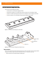
Five Slot Universal Charge Only Cradle
The Five Slot Universal Charge Only Cradle:
• Provides power for operating and charging the MC40.
• Simultaneously charges up to five MC40s and provides mounting for a Four Slot Battery Charger.
• Consists of a cradle base and optional cups that can be configured for various charging requirements.
• Provides mounting for a Four Slot Battery Charger (requires separate power supply).
Figure 2-9 Five Slot Universal Charge Only Cradle Base
Battery Charger
Cup
Universal Blank Slot
Cover
Charging Cup
Figure 2-10 Five Slot Universal Charge Only Cradle with Cups
Cup Installation
The Five Slot Universal Charge Only Cradle ships without any cradle cups installed. To base accepts the MC40
Charging Cup, Battery Charger Cup and Universal Blank Slot Cover. To install the cradle cups:
1.
Remove power from the cradle base before installing cups.
Accessories 2 - 11
2.
Align the lip of the cup with the slot on the front of the cradle. Ensure that the cup is positioned within the
Slot Alignment Tabs.
Figure 2-11 Five Slot Universal Charge Only Cradle Cup Installation
3.
Slide the lip into the slot and rotate the cup until it is flat on the cradle base.
4.
Using a Phillips screwdriver, secure the cup to the charger base using the two screws provided with the
cup.
Figure 2-12 Securing Cup to Base
5.
Each slot on the Cradle Base must have a cup installed.
6.
Repeat for each additional cup.
2 - 12 MC40 Integrator Guide
Four Slot Battery Charger Installation
To install a Four Slot Battery Charger:
1.
Install a Battery Charger Cup. See Cup Installation on page 2-10.
2.
Align the mounting slots on the bottom of the Four Slot Battery Charger with the screws on the cup.
3.
Slide the Four Slot Battery Charger down until it snaps into place.
Figure 2-13 Multi Slot Universal Charge Only Cradle Four Slot Battery Charger Installation
Power
Use one power supply to provide power to the Charging Base to power the Charging Cups. A separate power
supply is required for each Four Slot Battery Charger installed. The power supply is connected directly to the
For Slot Battery Charger.
Accessories 2 - 13
Figure 2-14 Five Slot Universal Charge Only Cradle Power Connections
The Charging Cup contains an insert. Remove the insert when charging an MC40 with a rubber boot.
Figure 2-15 Remove Insert
Charging
Insert the MC40 into a slot to begin charging.
The Right LED indicates the status of the battery charging in the MC40. See Table 1-1 on page 1-3 for
charging status indications. The 2680 mAh battery charges in approximately four hours.
2 - 14 MC40 Integrator Guide
Charge batteries in temperatures from 0 °C to 40 °C (32 °F to 104 °F). Charging is intelligently controlled by the
MC40. To accomplish this, for small periods of time, the MC40 alternately enables and disables battery
charging to keep the battery at acceptable temperatures. The MC40 indicates when charging is disabled due to
abnormal temperatures via the Battery Charge LED. See Table 1-1 on page 1-3.
Figure 2-16 Charging MC40 and Spare Battery
Accessories 2 - 15
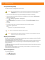
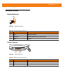
Finger Strap
Use the optional finger strap to securely hold the MC40 while working. To install the finger strap:
1.
Press the Power button until the Device options menu appears.
2.
Touch Power off.
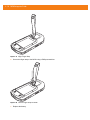
3.
Remove the battery.
Figure 2-17 Remove Battery
4.
Using a Phillips screwdriver, remove the two screws securing the rubber plug to the MC40.
Figure 2-18 Remove Rubber Plug
5.
Align the screws in the bracket of the finger strap with the mounting holes on the MC40.
2 - 16 MC40 Integrator Guide
Figure 2-19 Align Finger Strap
6.
Secure the finger strap to the MC40 using a Phillips screwdriver.
Figure 2-20 Secure Finger Strap to MC40
7.
Replace the battery.
Accessories 2 - 17
Figure 2-21 Install Battery
2 - 18 MC40 Integrator Guide
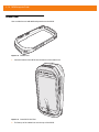
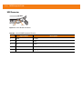
Rubber Boot
Use to rubber boot to add additional protection to the MC40.
Figure 2-22 Rubber Boot
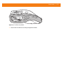
1.
Insert the bottom of the MC40 into the bottom of the rubber boot.
Figure 2-23 Insert MC40 into Boot
2.
Pull the top of the rubber boot over the top of the MC40.
Accessories 2 - 19
Figure 2-24 Pull Boot Over MC40
3.
Ensure that the rubber boot is sitting flat against the MC40.
2 - 20 MC40 Integrator Guide
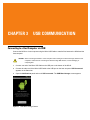
CHAPTER 3
USB COMMUNICATION
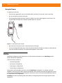
Connecting to a Host Computer via USB
Connect the MC40 to a host computer using the Micro USB Cable to transfer files between the MC40 and the
host computer.
CAUTION
When connecting the MC40 to a host computer and mounting its On-device Storage, follow the host
computer’s instructions for connecting and disconnecting USB devices, to avoid damaging or
corrupting files.
1.
Connect one end of the Micro USB Cable to the USB port on the bottom of the MC40.
2.
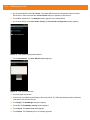
Connect the other end of the Micro USB Cable to the USB port on the host computer. USB Connected
appears on the Status bar.
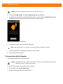
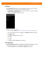
3.
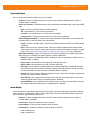
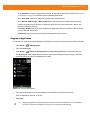
Open the Notifications panel and touch USB connected. The USB Mass Storage screen appears.
Figure 3-1 USB Mass Storage Screen
3-2
MC40 Integrator Guide
CAUTION
Ensure that all applications are not running. Loss of data may occur.
4.
Touch Turn on USB storage. The Turn on USB Storage dialog box appears.
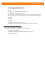
5.
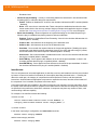
Touch OK. When the MC40 is connected as USB storage, the screen indicates USB storage is in use.
The MC40’s On-device Storage is mounted as a drive on the host computer.
Figure 3-2 USB Storage In Use Window
6.
On the host computer, open a file explorer application.
NOTE While USB storage is in use, access to the On-device Storage is disabled on the MC40.
7.
Locate the MC40 as a removable drive and open to view contents.
8.
Copy or delete files as required.
Disconnect from the Host Computer
To disconnect the MC40 from the host computer:
CAUTION
Carefully follow the host computer’s instructions to unmount the On-device Storage and disconnect
USB devices correctly to avoid losing information.
1.
On the host computer, unmount the On-device Storage.
2.
On the MC40, touch Turn off USB storage.
3.
Disconnect the Micro USB cable from the MC40.
CHAPTER 4
DATAWEDGE
CONFIGURATION
Introduction
DataWedge is an application that reads data, processes the data and sends the data to an application.
Basic Scanning
Scanning can be performed using either the Scan Module, Scan/MSR Module or the rear-facing camera.
Using the Imager
To capture bar code data:
1.
Ensure that an application is open on the MC40 and a text field is in focus (text cursor in text field).
2.
Aim the exit window at a bar code.
3.
Press and hold the Right Scan/Action button. The red laser aiming pattern turns on to assist in aiming.
Ensure that the bar code is within the area formed by the aiming pattern. The Left and Right LEDs light red
to indicate that data capture is in process.
Figure 4-1 Data Capture
4.
The Left and Right LEDs light green, a beep sounds and the MC40 vibrates, by default, to indicate the bar
code was decoded successfully. The captured data appears in the text field.
4-2
MC40 Integrator Guide
Using the Camera
To capture bar code data:
1.
Ensure that an application is open on the MC40 and a text field is in focus (text cursor in text field).
2.
Aim the rear-facing camera at a bar code.
3.
Press and hold the Right Scan/Action button. By default, a preview window appears on the screen. The
Left and Right LEDs light red to indicate that data capture is in process.
Figure 4-2 Data Capture with Camera
4.
Move the MC40 until the bar code is centered under the red target.
5.
The Left and Right LEDs light green, a beep sounds and the MC40 vibrates, by default, to indicate the bar
code was decoded successfully. The captured data appears in the text field.
Profiles
DataWedge is based on profiles and plug-ins. A profile contains information on how DataWedge should
behave with different applications.
Profile information consists of:
• Associated application
• Input plug-in configurations
• Output plug-in configurations
• Process plug-in configurations.
Using profiles, each application can have a specific DataWedge configuration. For example, each user
application can have a profile which outputs scanned data in the required format when that application comes
to the foreground. DataWedge can be configured to process the same set of captured data differently based on
the requirements of each application.
DataWedge includes the following visible and hidden pre-configured profiles which support specific built-in
applications:
DataWedge Configuration
4-3
• Visible profiles:
• Profile0 - created automatically the first time DataWedge runs. Generic profile used when there are
no user created profiles associated with an application.
• Launcher - disables scanning when the Launcher is in foreground.
• DWDemo - launchers the DW Demo application and displays the captured data in the application.
• Hidden profiles (not shown to the MC40):
• RD Client - provides support for MSP.
• MSP Agent - provides support for MSP.
• MspUserAttribute - provides support for MSP.
• Camera - disables scanning when the default camera application is in foreground.
• RhoElements - disables scanning when RhoElements is in foreground.
Profile0
Profile0 can be edited but cannot be associated with an application. That is, DataWedge allows manipulation
of plug-in settings for Profile0 but it does not allow assignment of a foreground application. This configuration
allows DataWedge to send output data to any foreground application other than applications associated with
user-defined profiles when Profile0 is enabled.
Profile0 can be disabled to allow DataWedge to only send output data to those applications which are
associated in user-defined profiles. For example, create a profile associating a specific application, disable
Profile0 and then scan. DataWedge only sends data to the application specified in the user-created profile.
This adds additional security to DataWedge enabling the sending of data only to specified applications.
Plug-ins
A plug-in is a software module utilized in DataWedge to extend its functionality to encompass technologies
such as bar code scanning. The plug-ins can be categorized into three types based on their operations:
• Input Plug-ins
• Output Plug-ins
• Process Plug-ins.
Input Plug-ins
An Input Plug-in supports an input device, such as a bar code scanner contained in, or attached to the MC40.
DataWedge contains base plug-ins for these input devices.
Bar Code Scanner Input Plug-in
The Bar Code Scanner Input Plug-in is responsible for reading data from the integrated bar code scanner and
supports different types of bar code readers including laser, imager and internal camera. Raw data read from
the bar code scanner can be processed or formatted using Process Plug-ins as required. DataWedge has
built-in feedback functionality for the bar code scanner to issue user alerts. The feedback settings can be
configured according to user requirement.
4-4
MC40 Integrator Guide
Process Plug-ins
Process Plug-ins are used in DataWedge to manipulate the received data according to the requirement, before
sending to the foreground application via the Output Plug-in.
Basic Data Formatting Process Plug-in
The Basic Data Formatting Plug-in allows DataWedge to add a prefix and/or a suffix to the captured data
before passing it to an Output Plug-in.
Output Plug-ins
Output Plug-ins are responsible for sending the data from Input Plug-ins to a foreground application on the
MC40.
Keystroke Output Plug-in
The Keystroke Output Plug-in collects and sends data received from the Input Plug-in to the foreground
applications by emulating keystrokes.
Intent Output Plug-in
The Intent Output Plug-in collects and sends data received from the Input Plug-ins to foreground applications
using the Android Intent mechanism.
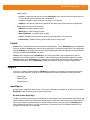
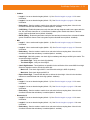
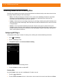
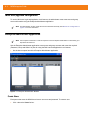
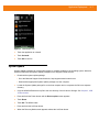
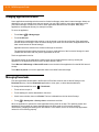
Profiles Screen
To launch DataWedge, touch
profiles appear:
> DataWedge. The DataWedge Profiles screen appears. By default, two
• Profile0
• Launcher
• DWDemo.
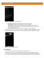
Profile0 is the default profile and is used when no other profile can be applied.
Figure 4-3 DataWedge Profiles Screen
DataWedge Configuration
4-5
Profile names are color coded. Enabled profiles are white and disabled profiles are gray.
To configure a profile touch the profile name.
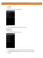
Profile Context Menu
Touch and hold a profile to open a context menu that allows additional actions to be performed on the selected
profile.
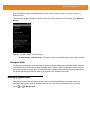
Figure 4-4 Profile Context Menu
The profile context menu allows the profile to be edited (same as just tapping on a profile), renamed or deleted.
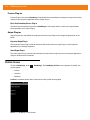
Options Menu
Touch
to open the options menu.
Figure 4-5 DataWedge Options Menu
The menu provides options to create a new profiles, access to general DataWedge settings and DataWedge
version information.
4-6
MC40 Integrator Guide
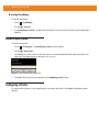
Disabling DataWedge
To disable DataWedge:
1.
Touch
> DataWedge.
2.
Touch
3.
Touch DataWedge enabled. The green check disappears from the checkbox indicating that DataWedge is
disabled.
> Settings.
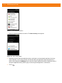
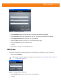
Create a New Profile
To create a new profile:
1.
Touch
> DataWedge. The DataWedge Profiles window appears.
2.
Touch
3.
In the dialog box, enter a name for the new profile. It is recommended that profile names be unique and
made up of only alpha-numeric characters (A-Z, a-z, 0-9).
> New profile.
Figure 4-6 New Profile Name Dialog Box
4.
Touch OK. The new profile name appears in the DataWedge profile screen.
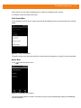
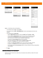
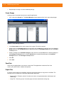
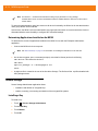
Configuring a Profile
To configure the Profile0 or a user-created profile, touch the profile name. The Profile configuration screen
appears.
DataWedge Configuration
4-7
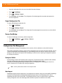
Figure 4-7 Profile Configuration Screen
• Profile enabled - Enables or disables this profile. A check in the checkbox indicates that the profile is
enabled.
Applications
Use Applications option to associate applications with this profile.
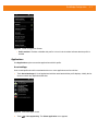
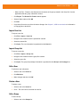
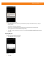
Associated Apps
User created profiles should be associated with one or more applications and its activities.
1.
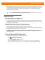
Touch Associated apps. A list of applications/activities associated with the profile displays. Initially the list
does not contain any applications/activities.
Figure 4-8 Associated Apps Screen
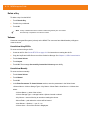
2.
Touch
> New app/activity. The Select application menu appears.
4-8
MC40 Integrator Guide
Figure 4-9 Select Application Menu
3.
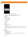
Select the desired application from the list. The Select activity menu appears.
Figure 4-10 Select Activity Menu
4.
Selecting the activity adds that application/activity combination to the associated application list for that
profile. Selecting * as the activity results in all activities within that application being associated to the
profile. During operation, DataWedge tries to match the specific application/activity combinations with the
foreground application/activity before trying to match the general application/* combinations.
5.
Touch
.
DataWedge Configuration
4-9
Figure 4-11 Selected Application/Activity
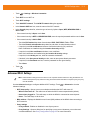
Barcode Input
Use the Bar Code Input options to configure the Bar Code Scanner Input Plug-in for the profile.
Enabled
Enables or disables this plug-in. A check in the checkbox indicates that the plug-in is enabled.
Scanner Selection
Configures which scanning device to use for data capture.
• Auto - Automatically determines the best scanning device. If a Scan Module or Scan/MSR Module is
installed on the MC40, then the 2D imager is selected. Otherwise the camera is selected.
• Camera Scanner - Scanning is performed with the rear-facing camera.
• 2D Imager - Scanning is performed using the installed Scan or Scan/MSR module.
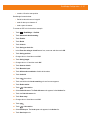
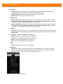
Decoders
Configures which bar code decoders are enabled or disabled. For best performance disable all unnecessary
decoders.
Touch Decoders. The Barcode input screen appears. A check in the checkbox indicates that the decoder is
enabled. By default the most commonly used decoders are enabled (shown below with an asterisk). The
supported decoders are:
• UPC-A*
UPC-E0*
EAN-13*
• EAN-8*
Code 128*
Code 39*
• Interleaved 2 of 5
GS1 DataBar*
GS1 DataBar Limited
• GS1 DataBar Expanded*
Datamatrix*
QR Code*
• PDF417*
Composite AB
Composite C
• MicroQR
Aztec*
Maxicode*
4 - 10 MC40 Integrator Guide
• MicroPDF
USPostnet
USPlanet
• UK Postal
Japanese Postal
Australian Postal
• Canadian Postal
Dutch Postal
US4state FICS
• Codabar*
MSI
Code 93
• Trioptic 39
Discrete 2 of 5
Chinese 2 of 5
• Korean 3 of 5
Code 11
TLC 39
• Webcode
Matrix 2 of 5
UPC-E1
Touch
to return to the previous screen.
Decoder Params
Use Decode Params to configure individual decoder parameters. Touch Decode Params. The Decode
params screen appears.
Touch the decoder parameter to modify.
• UPCA
• Report Check Digit - The check digit is the last character of the symbol used to verify the integrity of
the data. Enables or disables this option. A check in the checkbox indicates that the option is enabled
(default - enabled).
• Preamble - Preamble characters are part of the UPC symbol consisting of Country Code and System
Character. There are three options for transmitting a UPCA preamble:
• Preamble None - Transmit no preamble.
• Preamble Sys Char - Transmit System Character only (default).
• Preamble Country and Sys Char - Transmit System Character and Country Code (“0” for USA).
Select the appropriate option to match the host system.
• UPCE0
• Report Check Digit - The check digit is the last character of the symbol used to verify the integrity of
the data. Enables or disables this option. A check in the checkbox indicates that the option is enabled
(default - disabled).
• Preamble - Preamble characters are part of the UPC symbol consisting of Country Code and System
Character. There are three options for transmitting a UPCE0 preamble:
• Preamble Sys Char - Transmit System Character only.
• Preamble Country and Sys Char - Transmit System Character and Country Code (“0” for USA).
• Preamble None - Transmit no preamble (default).
Select the appropriate option to match the host system.
• Convert UPCE0 To UPCA - Enable to convert UPCE0 (zero suppressed) decoded data to UPC-A
format before transmission. After conversion, the data follows UPC-A format and is affected by UPC-A
programming selections. Disable to transmit UPCE0 decoded data as UPCE0 data, without
conversion (default - disabled).
DataWedge Configuration 4 - 11
• Code128
• Length1 - Use to set decode lengths (default - 0). See Decode Lengths on page 4-15 for more
information.
• Length2 - Use to set decode lengths (default - 55). See Decode Lengths on page 4-15 for more
information.
• Redundancy - Sets the reader to read the bar code twice before accepting data. A check in the
checkbox indicates that redundancy is enabled (default - disabled).
• Enable Plain Code 128 - Flag to enable other 128 sub types (besides GS1-128 and ISBT-128).
• Enable GS1-128 - Set the GS1 128 subtype. A check in the checkbox indicates that the option is
enabled (default - enabled).
• Enable ISBT128 - Set the ISBT128 subtype. A check in the checkbox indicates that the option is
enabled (default - enabled).
• ISBT128 Concatenation Mode - Select an option for concatenating pairs of ISBT code types:
• Concat Mode Never - Do not concatenate pairs of ISBT codes encountered (default).
• Concat Mode Always - There must be two ISBT codes in order to decode and perform
concatenation. Does not decode single ISBT symbols.
• Concat Mode Auto - Decodes and concatenates pairs of ISBT codes immediately. If only a single
ISBT symbol is present, the device must decode the symbol the number of times set via
Redundancy - Code128 before transmitting its data to confirm that there is no additional ISBT
symbol.
• Check ISBT Table - The ISBT specification includes a table that lists several types of ISBT bar codes
that are commonly used in pairs. If ISBT128 Concat Mode is set, enable Check ISBT Table to
concatenate only those pairs found in this table. Other types of ISBT codes are not concatenated. A
check in the checkbox indicates that redundancy is enabled (default - disabled).
• Security Level - The scanner offers four levels of decode security for Code 128 bar codes. Select
increasing levels of security for decreasing levels of bar code quality. There is an inverse relationship
between security and scanner aggressiveness, so choose only that level of security necessary for any
given application.
• Security Level 0 - This setting allows the scanner to operate in its most aggressive state, while
providing sufficient security in decoding most “in-spec” bar codes.
• Security Level 1 - This setting eliminates most misdecodes (default).
• Security Level 2 - Select this option if Security level 1 fails to eliminate misdecodes.
• Security Level 3 - If Security Level 2 is selected and misdecodes still occur, select this security
level. Be advised, selecting this option is an extreme measure against mis-decoding severely out
of spec bar codes. Selecting this level of security significantly impairs the decoding ability of the
scanner. If this level of security is needed, try to improve the quality of the bar codes.
• Code39
• Length1 - Use to set decode lengths (default - 0). See Decode Lengths on page 4-15 for more
information.
• Length2 - Use to set decode lengths 4 (default - 55). See Decode Lengths on page 4-15 for more
information.
• Verify Check Digit - Enable this feature to check the integrity of all Code 39 symbols to verify that the
data complies with a specified check digit algorithm. The digital scanner decodes only those Code 39
4 - 12 MC40 Integrator Guide
symbols that include a modulo 43 check digit. Enable this feature only if the Code 39 symbols contain
a modulo 43 check digit (default - disabled).
• Report Check Digit - Transmit Code 39 data with or without the check digit. A check in the checkbox
indicates to send Code 39 data with check digit (default - disabled).
• Full ASCII - Code 39 Full ASCII is a variant of Code 39 that pairs characters to encode the full ASCII
character set. To enable or disable Code 39 Full ASCII (default - disabled),
• Redundancy - Sets the reader to read the bar code twice before accepting data. A check in the
checkbox indicates that redundancy is enabled (default - disabled).
• Convert Code39 To Code32 - Code 32 is a variant of Code 39 used by the Italian pharmaceutical
industry. Scan the appropriate bar code below to enable or disable converting Code 39 to Code 32
(default - disabled).
• Report Code32 Prefix - Scan the appropriate bar code to enable or disable adding the prefix
character “A” to all Code 32 bar codes (default - disabled).
• Security Level - Options: Security level 0, Security Level 1, Security Level 2 and Security Level 3
(default - Security level 1).
• Interleaved 2of5
• Length1 - Use to set decode lengths (default - 14). See Decode Lengths on page 4-15 for more
information.
• Length2 - Use to set decode lengths (default - 10). See Decode Lengths on page 4-15 for more
information.
• Redundancy - Sets the reader to read the bar code twice before accepting data. A check in the
checkbox indicates that redundancy is enabled (default - enabled).
• Check Digit
• No Check Digit - A check digit is not used. (default)
• USS Check Digit - Select to check the integrity of all Interleaved 2 of 5 symbols to verify the data
complies with either the Uniform Symbology Specification (USS) check digit algorithm.
• OPCC Check Digit - Select to check the integrity of all Interleaved 2 of 5 symbols to verify the data
complies with either the Optical Product Code Council (OPCC) check digit algorithm.
• Report Check Digit - Transmit Interleaved 2 of 5 data with or without the check digit. A check in the
checkbox indicates to send I2of5 data with check digit (default - disabled).
• Convert ITF-14 To EAN13 - Convert 14-character Interleaved 2 of 5 bar codes to EAN-13, and
transmit as EAN-13. The Interleaved 2 of 5 bar code must be enabled and must have a leading zero
and a valid EAN-13 check digit. A check in the checkbox indicates that the option is enabled (default disabled).
• Composite AB
• UCC Link Mode
• Link Flag ignored - 1D component is transmitted regardless of whether a 2D component is
detected.
• Always Linked - 1D and the 2D components are transmitted. If 2D is not present, the 1D
component is not transmitted.
• Auto Discriminate - the digital scanner determines if there is a 2D portion, then transmits the 1D
component, as well as the 2D portion if present. (default).
• UK Postal
• Report Check Digit - Transmit UK Postal data with or without the check digit. A check in the
checkbox indicates to send UK Postal data with check digit (default - disabled).
DataWedge Configuration 4 - 13
• Codabar
• Length1 - Use to set decode lengths (default - 6). See Decode Lengths on page 4-15 for more
information.
• Length2 - Use to set decode lengths (default - 55). See Decode Lengths on page 4-15 for more
information.
• Redundancy - Sets the reader to read the bar code twice before accepting data. A check in the
checkbox indicates that redundancy is enabled (default - enabled).
• CLSI Editing - Enable this parameter to strip the start and stop characters and insert a space after the
first, fifth, and tenth characters of a 14-character Codabar symbol. Enable this feature if the host
system requires this data format (default - disabled).
• NOTIS Editing - Enable this parameter to strip the start and stop characters from a decoded Codabar
symbol. Enable this feature if the host system requires this data format (default - disabled).
• MSI
• Length 1 - Use to set decode lengths (default - 4). See Decode Lengths on page 4-15 for more
information.
• Length 2 - Use to set decode lengths (default - 55). See Decode Lengths on page 4-15 for more
information.
• Redundancy - Sets the reader to read the bar code twice before accepting data. A check in the
checkbox indicates that redundancy is enabled (default - enabled).
• Check Digit - With MSI symbols, one check digit is mandatory and always verified by the reader. The
second check digit is optional.
• One Check Digit - Verify one check digit (default).
• Two Check Digits - Verify two check digits.
• Check Digit Scheme - Two algorithms are possible for the verification of the second MSI check digit.
Select the algorithm used to encode the check digit.
• Mod-11-10 - First check digit is MOD 11 and second check digit is MOD 10 (default).
• Mod-10-10 - Both check digits are MOD 10.
• Report Check Digit - Transmit MSI data with or without the check digit. A check in the checkbox
indicates to send MSI data with check digit (default - disabled).
• Code93
• Length1 - Use to set decode lengths (default - 0). See Decode Lengths on page 4-15 for more
information.
• Length2 - Use to set decode lengths (default - 55). See Decode Lengths on page 4-15 for more
information.
• Redundancy - Sets the reader to read the bar code twice before accepting data. A check in the
checkbox indicates that redundancy is enabled (default - disabled).
• Discrete 2 of 5
• Length1 - Use to set decode lengths (default - 0). See Decode Lengths on page 4-15 for more
information.
• Length2 - Use to set decode lengths (default - 14). See Decode Lengths on page 4-15 for more
information.
• Redundancy - Sets the reader to read the bar code twice before accepting data. A check in the
checkbox indicates that redundancy is enabled (default - enabled).
4 - 14 MC40 Integrator Guide
• Code11
• Length1 - Use to set decode lengths (default - 4). See Decode Lengths on page 4-15 for more
information.
• Length2 - Use to set decode lengths (default - 55). See Decode Lengths on page 4-15 for more
information.
• Redundancy - Sets the reader to read the bar code twice before accepting data. A check in the
checkbox indicates that redundancy is enabled (default - enabled).
• Verify Check Digit - Check the integrity of all Code 11 symbols to verify that the data complies with
the specified check digit algorithm. This selects the check digit mechanism for the decoded Code 11
bar code.
• No Check Digit - Do not verify check digit.
• 1 Check Digit - Bar code contains one check digit (default).
• 2 Check Digits - bar code contains two check digits.
• Report Check DIgit - Transmit Code 11 data with or without the check digit. A check in the checkbox
indicates to send Code 11 data with check digit (default - disabled).
• Webcode
• Webcode Subtype - Enables the decoding of the GT Webcode subtype. A check in the checkbox
indicates that the option is enabled (default - disabled).
• Matrix 2 of 5
• Length1 - Use to set decode lengths (default - 0). See Decode Lengths on page 4-15 for more
information.
• Length2 - Use to set decode lengths (default - 0). See Decode Lengths on page 4-15 for more
information.
• Redundancy - Sets the reader to read the bar code twice before accepting data. A check in the
checkbox indicates that redundancy is enabled (default - disabled).
• Report Check Digit - Transmit Matrix 2 of 5 data with or without the check digit. A check in the
checkbox indicates to send Matrix 2 of 5 data with check digit (default - enabled).
• Verify Check Digit - Enable this feature to check the integrity of all Matrix 2 of 5 symbols to verify that
the data complies with a specified check digit algorithm (default - enabled).
• UPCE1
• Report Check Digit - The check digit is the last character of the symbol used to verify the integrity of
the data. Enables or disables this option. A check in the checkbox indicates that the option is enabled
(default - disabled).
• Preamble - Preamble characters are part of the UPC symbol consisting of Country Code and System
Character. There are three options for transmitting a UPCE1 preamble:
• Preamble Sys Char - Transmit System Character only.
• Preamble Country and Sys Char - Transmit System Character and Country Code (“0” for USA).
• Preamble None - Transmit no preamble (default).
Select the appropriate option to match the host system.
• Convert UPCE1 To UPCA - Enable this to convert UPCE1 decoded data to UPC-A format before
transmission. After conversion, the data follows UPC-A format and is affected by UPC-A programming
selections. Disable this to transmit UPCE1 decoded data as UPCE1 data, without conversion (default
- disabled).
DataWedge Configuration 4 - 15
Decode Lengths
The allowable decode lengths are specified by options Length1 and Length2 as follows:
• Variable length: Decode symbols containing any number of characters.
• Set both Length1 and Length2 to 0.
• Range: Decode a symbol with a specific length range (from a to b, including a and b).
• Set Length1 to a and set Length2 to b.
• Two Discrete Lengths: Decode only symbols containing either of two selected lengths.
• Set either Length1 or Length2 to the specific lengths.
• One Discrete Length: Decode only symbols containing a specific length.
• Set both Length1 and Length2 to the specific length.
UPC EAN Params
Allows the configuration of the parameters that apply to more than one UPC or EAN decoder.
• Security Level - The scanner offers four levels of decode security for UPC/EAN bar codes. Select higher
security levels for lower quality bar codes. There is an inverse relationship between security and decode
speed, so be sure to choose only that level of security necessary for the application.
• Level 0 - This default setting allows the scanner to operate fastest, while providing sufficient security
in decoding “in-spec” UPC/EAN bar codes (default).
• Level 1 - As bar code quality levels diminish, certain characters become prone to misdecodes before
others (i.e., 1, 2, 7, 8). If the scanner is misdecoding poorly printed bar codes, and the misdecodes
are limited to these characters, select this security level.
• Level 2 - If the scanner is misdecoding poorly printed bar codes, and the misdecodes are not limited
to characters 1, 2, 7, and 8, select this security level.
• Level 3 - If the scanner is still misdecoding, select this security level. Be advised, selecting this option
is an extreme measure against misdecoding severely out of spec bar codes. Selecting this level of
security can significantly impair the decoding ability of the scanner. If this level of security is
necessary, try to improve the quality of the bar codes.
• Supplemental2 - Enables or disables this option. A check in the checkbox indicates that the option is
enabled.
• Supplemental5 - Enables or disables this option. A check in the checkbox indicates that the option is
enabled.
• Supplemental Mode
• No Supplementals - the scanner is presented with a UPC/EAN plus supplemental symbol, the
scanner decodes UPC/EAN and ignores the supplemental characters (default).
• Supplemental Always - the scanner only decodes UPC/EAN symbols with supplemental characters,
and ignores symbols without supplementals.
• Supplements Auto - the scanner decodes UPC/EAN symbols with supplemental characters
immediately. If the symbol does not have a supplemental, the scanner must decode the bar code the
number of times set via UPC/EAN Supplemental Redundancy before transmitting its data to confirm
that there is no supplemental.
• Supplemental Smart - Enables smart supplementals. In this mode the decoder returns the decoded
value of the main block right away if it does not belong to one of the following supplemental types:
378, 379, 977, 978, 979, 414, 419, 434 or 439. If the bar code starts with one of the prefixes it
4 - 16 MC40 Integrator Guide
searches the image more aggressively for a supplemental. Tries to scan the supplemental if it is
present. If the supplemental scanning failed, then the main bar code is returned.
• Supplemental 378-379 - Enables (auto-discriminate) supplemental for UPC/EAN codes starting with
378 or 379. Disables reading of supplementals for any other UPC/EAN bar code not starting with 378
or 379. Tries to scan the supplemental if it is present. If the supplemental scanning failed, then the
main bar code is returned.
• Supplemental 978-979 - Enables (auto-discriminate) supplemental for UPC/EAN codes starting with
978 or 979. Disables reading of supplementals for another UPC/EAN bar code not starting with 978 or
979. Tries to scan the supplemental if it is present. If the supplemental scanning failed, then the main
barcode is returned.
• Supplemental 414-419-434-439 - Enables (auto-discriminate) supplemental for UPC/EAN codes
starting with 414, 419, 434 or 439. Disables reading of supplementals for another UPC/EAN bar code
not starting with 414, 419, 434 or 439. Tries to scan the supplemental if it is present. If the
supplemental scanning failed, then the main bar code is returned.
• Supplemental 977 - Enables (auto-discriminate) supplemental for UPC/EAN codes starting with 977.
Disables reading of supplementals for another UPC/EAN barcode not starting with 977. Tries to scan
the supplemental if it is present. If the supplemental scanning failed, then the main bar code is
returned.
• Retry Count - Retry count for auto-discriminating for supplementals. Possible values are 2 to 20
inclusive. Note that this flag is only considered if Supplemental Mode - UPC EAN is set to one of the
following values: Supplementals Auto, Supplementals Smart, Supplementals 378-379,
Supplementals 978-979, Supplementals 977 or Supplementals 414-419-434-439 (2 to 20, default 10).
• Bookland - Enable or disable this option. A check in the checkbox indicates that the option is enabled.
• Coupon - Enables Coupon code decoding. Note that in order to successfully decode Coupon codes, all
of the correct decoders must be enabled. A check in the checkbox indicates that the option is enabled.
• Convert DataBar To UPC EAN - If this is set it converts DataBar bar codes to UPC/EAN format. For this
setting to work UPC/EAN symbologies must be enabled. A check in the checkbox indicates that the
option is enabled.
Reader Params
Allows the configuration of parameters specific to the selected bar code reader.
• Beam Timer - Sets the maximum amount of time that the reader remains on (0 - 60,000 ms in
increments of 100 ms). A value of 0 sets the reader to stay on indefinitely (default -15000).
• Linear Security Level - Sets the number of times a bar code is read to confirm an accurate decode.
• Security Redundancy and Length - Two times read redundancy based on redundancy flags and
code length.
• Security Short or Codabar - Two times read redundancy if short bar code or Codabar.
• Security All Twice - Two times read redundancy for all bar codes (default).
• Security Long and Short - Two times read redundancy for long bar codes, three times for short bar
codes.
• Security All Thrice - Three times read redundancy for all bar codes.
DataWedge Configuration 4 - 17
• Picklist - Allows the imager to decode only the bar code that is directly under the cross-hair/reticle (+)
part of the pattern. This feature is useful in applications where multiple bar codes may appear in the field
of view during a decode session and only one of them is targeted for decode.
• Disable – Disables Picklist mode. Any bar code within the field of view can be decoded (default).
• Centered - Enables the Picklist mode so that only the bar code in the center of the image is decoded.
This is most useful when used in conjunction with the static and dynamic reticle viewfinder modes.
Note: This mode is only valid for decoder modules that supports a viewfinder. If one tries to set this for
a unsupported decoder then the device would issue an error. (Camera scanner only).
• Reticle - Enables the Picklist mode so that only the bar code that is directly under the cross-hair
(reticle) is decoded. This is useful when used in conjunction with the static and dynamic reticle
viewfinder modes. (Scan Module Only)
• LCD Mode - Enables or disables LCD mode. LCD mode enhances the ability of the imager to read bar
codes from LCD displays such as cellphones (Scan Module Only).
• Disable - Disables the LCD mode
• Enable - Enables LCD mode.
NOTE When using the LCD mode, a degradation in performance may be observed and the aiming crosshair may
blink until the bar code is decoded.
• Inverse 1D Mode - This parameter allows the user to select decoding on inverse 1D bar codes.
• Disable - Disables decoding of inverse 1D bar codes.
• Enable - Enables decoding of only inverse 1D bar codes.
• Auto - Allows decoding of both positive and inverse 1D bar codes.
• Viewfinder Mode - Configures the Viewfinder modes supported for camera scanning.
• Viewfinder Enabled - Enables only the viewfinder.
• Static Reticle - Enables the viewfinder and a red reticle in the center of the screen which helps
selecting the bar code (default).
Scan Params
Allows the configuration of Code Id and decode feedback options.
• Code ID Type - A Code ID character identifies the code type of a scanned bar code. This is useful when
the reader is decoding more than one code type. Select a code ID character to insert between the prefix
and the decoded symbol.
• Code ID Type None - No prefix (default).
• Code ID Type Aim - A standards based three character prefix.
• Code ID Type Symbol - A Symbol defined single character prefix.
NOTE Not all ringtones are fully supported as decode tones. Ringtones of longer length may be truncated when
used as a decode tone. The recommendation is to test the selected tone for operation before deployment
to a customer site.
• Decode Audio Feedback - Select an audio tone to sound upon a good decode.
• Decode Haptic Feedback - Enable the MC40 to vibrate upon a good decode (default - enabled).
4 - 18 MC40 Integrator Guide
MSR Input
Use MSR Input options to configure the MSR Input Plug-in for the profile.
Enabled
Enables or disables this plug-in. A check in the checkbox indicates that the plug-in is enabled.
Track Selection
There are up to three tracks of encoded data on a magnetic stripe. This option selects the tracks that will be
read and decoded.
• Any Track - All tracks on the magnetic stripe are read and decoded by the MSR.
• Require Track 1 Only - Only track 1 on the magnetic stripe is read and decoded by the MSR.
• Require Track 2 Only - Only track 2 on the magnetic stripe is read and decoded by the MSR.
• Require Track 1 & Track 2 - Only tracks 1 and 2 on the magnetic stripe are read and decoded by the
MSR.
• Require Track 3 Only - Only track 3 on the magnetic stripe is read and decoded by the MSR.
• Require Track 1 & Track 3 - Only tracks 1 and 3 on the magnetic stripe are read and decoded by the
MSR.
• Require Track 2 & Track 3 - Only tracks 2 and 3 on the magnetic stripe are read and decoded by the
MSR.
• Require All Three Tracks - All tracks on the magnetic stripe are read and decoded by the MSR.
• Any Track 1 & 2 - Either track 1 or 2 on the magnetic stripe are read and decoded by the MSR.
• Any Track 2 & 3 - Either tracks 2 or 3 on the magnetic stripe are read and decoded by the MSR.
Track Separator
Use Track Separator to add a character between decoded data. (default - 0Dh CR (carriage return)).
Sentinel/track 2 data
The MSR can be set to either send, or not send, the Start/End sentinel, and to send either the Track 2 account
number only, or all the encoded data on Track 2. The Track 2 setting does not affect the output of Track 1 and
Track 3.
• Don’t send start/end sentinel and send all data on Track 2 - Do not send Sentinel data and send all
Track 2 data.
• Send start/end sentinel and send all data on track 2 - Send Sentinel data and send all Track 2 data.
• Don’t send start/end sentinel and send account number on Track 2 - Do not send Sentinel data and
only send account number data from Track 2.
• Send start/end sentinel and send account number on Track 2 - Send Sentinel data and only send
account number data from Track 2.
DataWedge Configuration 4 - 19
Keystroke Output
Use to configure the Keystroke Output Plug-in for the profile.
• Enabled - Enables or disables this plug-in. A check in the checkbox indicates that the plug-in is
enabled (default - enabled).
• Action key character - Enabled decoding a special characters embedded within a bar code or MSR
data.
• None - Action key character feature is disabled (default).
• Tab - Tab character (\t) in a bar code is processed.
• Line feed - Line feed character (\t) in a bar code is processed.
• Carriage return - Carriage return character (\t) in a bar code is processed.
• Advanced data formatting - is a way to customizing data before transmission. Use advanced data
formatting (ADF) to edit scan data to suit requirements.
• Enable - Enables or disables ADF. A check in the checkbox indicates that ADF is enabled (default
- disabled).
• Rules - ADF uses rules to customize data. These rules perform detailed actions when the data
meets certain criteria. One rule may consist of single or multiple criteria applied to single or multiple
actions. See Generating Advanced Data Formatting Rules on page 4-22 for more information.
• Basic data formatting - Allows the configuration of any data formatting for the related Output Plug-in.
When the plug-in is disabled, any data is passed on without modification.
• Enabled - Enables or disables Basic Data Formatting. A check in the checkbox indicates that it is
enabled (default - enabled).
• Prefix to data - Add characters to the beginning of the data when sent.
• Suffix to data - Add characters to the end of the data when sent.
• Send data - Set to transfer the captured data to the foreground application. Disabling this option
prevents the actual data from being transmitted. However, the prefix and suffix strings, if present,
are still transmitted even when this option is disabled (default - enabled).
• Send as hex - Set to send the data in hexadecimal format. A check in the checkbox indicates that
the plug-in is enabled (default - disabled).
• Send TAB key - Set to append a tab character to the end of the processed data. A check in the
checkbox indicates that the plug-in is enabled (default - disabled).
• Send ENTER key - Set to append an Enter character to the end of the processed data. A check in
the checkbox indicates that the plug-in is enabled (default - disabled).
Intent Output
Allows configuration of the Intent Output Plug-in for the profile. The Intent Output Plug-in allows the captured
data to be sent to an application in the form of an implicit Intent. Refer to the Android Developer web site for
more information, http://developer.android.com.
• Enabled - Enables or disables this plug-in. A check in the checkbox indicates that the plug-in is
enabled (default - disabled).
• Intent action - Enter the Intent Action name (required).
• Intent category - Enter the Intent Category name (required).
• Intent delivery - Select the method by which the intent is delivered:
• Send via StartActivity
• Send via startService
4 - 20 MC40 Integrator Guide
• Broadcast intent
• Advanced data formatting - is a way to customizing data before transmission. Use advanced data
formatting (ADF) to edit scan data to suit requirements.
• Enable - Enables or disables ADF. A check in the checkbox indicates that ADF is enabled (default
- disabled).
• Rules - ADF uses rules to customize data. These rules perform detailed actions when the data
meets certain criteria. One rule may consist of single or multiple criteria applied to single or multiple
actions. See Generating Advanced Data Formatting Rules on page 4-22 for more information.
• Basic data formatting - Allows configuration of any data formatting for the related Output Plug-in.
When the plug-in is disabled any data is passed on without modification.
• Enabled - Enables or disables Basic Data Formatting. A check in the checkbox indicates that it is
enabled (default - enabled).
• Prefix to data - Add characters to the beginning of the data when sent.
• Suffix to data - Add characters to the end of the data when sent.
• Send data - Set to transfer the captured data to the foreground application. Disabling this option
prevents the actual data from being transmitted. However, the prefix and suffix strings, if present,
are still transmitted even when this option is disabled (default - enabled).
• Send as hex - Set to send the data in hexadecimal format. A check in the checkbox indicates that
the plug-in is enabled (default - disabled).
• Send TAB key - Set to append a tab character to the end of the processed data. A check in the
checkbox indicates that the plug-in is enabled (default - disabled).
• Send ENTER key - Set to append an Enter character to the end of the processed data. A check in
the checkbox indicates that the plug-in is enabled (default - disabled).
Intent Overview
The core components of an Android application (its activities, services, and broadcast receivers) are activated
by intents. An intent is a bundle of information (an Intent object) describing a desired action — including the
data to be acted upon, the category of component that should perform the action, and other pertinent
instructions. Android locates an appropriate component to respond to the intent, launches a new instance of
the component if one is needed, and passes it the Intent object.
Components advertise their capabilities, the kinds of intents they can respond to, through intent filters. Since
the system must learn which intents a component can handle before it launches the component, intent filters
are specified in the manifest as <intent-filter> elements. A component may have any number of filters, each
one describing a different capability.
For example, if the manifest contains the following:
<intent-filter . . . >
<action android:name=”android.intent.action.DEFAULT” />
<category android:name=”android.intent.category.MAIN” />
. . .
</intent-filter>
In the Intent output plug-in configuration, the Intent action would be:
android.intent.category.DEFAULT
and the Intent category would be:
android.intent.category.MAIN.
DataWedge Configuration 4 - 21
The Intent delivery option allows the method by which the intent is delivered to be specified. The delivery
mechanisms are Send via startActivity, Send via startService or Broadcast intent.
The decode related data added to the Intent’s bundle can be retrieved using the
Intent.getStringtExtra() and Intent.getSerializableExtra() calls, using the following String tags:
• String LABEL_TYPE_TAG = “com.motorolasolutions.emdk.datawedge.label_type”;
String contains the label type of the bar code.
• String DATA_STRING_TAG = “com.motorolasolutions.emdk.datawedge.data_string”;
String contains the output data as a String. In the case of concatenated bar codes, the decode data is
concatenated and sent out as a single string. In the case of MSR output, the data from the MSR tracks is
concatenated and sent out as a single string.
• String DECODE_DATA_TAG = “com.motorolasolutions.emdk.datawedge.decode_data”;
Decode data is returned as a list of byte arrays. In most cases there will be one byte array per decode.
For barcode symbologies that support concatenation e.g. Codabar, Code128, MicroPDF, etc., the
decoded data is stored in multiple byte arrays (one byte array per bar code). Clients can get data in each
byte array by passing an index.
The MSR related data added to the Intent's bundle can be retrieved using the Intent.getStringtExtra() and
Intent.getSerializableExtra() calls, using the following String tags:
• String MSR_DATA_TAG = “com.motorolasolutions.emdk.datawedge.msr_data”;
The data from the MSR tracks is concatenated and sent out as a byte array. The Start/end sentinels and
track separators are included as configured.
• String MSR_TRACK1_TAG = “com.motorolasolutions.emdk.datawedge.msr_track1”;
MSR track 1 data is returned as a byte array.
• String MSR_TRACK2_TAG = “com.motorolasolutions.emdk.datawedge.msr_track2”;
MSR track 2 data is returned as a byte array.
• String MSR_TRACK3_TAG = “com.motorolasolutions.emdk.datawedge.msr_track3”;
MSR track 3 data is returned as a byte array.
• String MSR_TRACK1_STATUS_TAG = “com.motorolasolutions.emdk.datawedge.msr_track1_status”;
MSR track 1 decode status as an Integer where 0 indicates a successful decode.
• String MSR_TRACK2_STATUS_TAG = “com.motorolasolutions.emdk.datawedge.msr_track2_status”;
MSR track 2 decode status as an Integer where 0 indicates a successful decode.
• String MSR_TRACK3_STATUS_TAG = “com.motorolasolutions.emdk.datawedge.msr_track3_status”;
MSR track 3 decode status as an Integer where 0 indicates a successful decode.
Most scanning applications might want the user to be able to decode data and for that decode data to be sent
to the *current* activity but not necessarily displayed. If this is the case, then the activity needs to be marked
as ‘singleTop’ in its AndroidManifest.xml file. If your activity is not defined as singleTop, then on every decode,
the system will create another copy of your Activity and send the decode data to this second copy.
Finally there will be a configuration option for each process plug-in so that the process plug-in can be
configured specifically for the intent output, which in this case is the basic data formatting process plug-in.
4 - 22 MC40 Integrator Guide
Generating Advanced Data Formatting Rules
The ADF plug-in applies rules (actions to be performed based on defined criteria) to the data received via the
Input plug-in before sending it to the Output plug-in.
• Rules - The ADF process plug-in consists of one or more rules. DataWedge formats the output data
according to the first matching rule. A rule is a combination of criteria and a set of actions to be
performed, upon fulfillment of the criteria set in the rule.
• Criteria - Criteria can be set according to Input plug-in, symbology, matching string within the data (at the
specified position) and/or data length. Received data must match the defined criteria in order for the data
to be processed.
• Actions - A set of procedures defined to format data. There are four types of actions which are for
formatting cursor movement, data modification, data sending and delay specifications. An action can be
defined to send the first number of characters to the Output plug-in, pad the output data with spaces or
zeros, remove spaces in data, etc.
Configuring ADF Plug-in
Configuring the ADF plug-in consists of creating a rule, defining the criteria and defining the actions.
1.
Touch
> DataWedge.
2.
Touch a DataWedge profile.
3.
In Keystroke output, touch Advanced data formatting.
Figure 4-12 Advanced Data Formatting Screen
4.
Touch the Enable checkbox to enable ADF.
Creating a Rule
By default, Rule0, is the only rule in the Rules list. To add a new rule:
1.
Touch the
> New rule.
2.
Touch the Enter rule name text box. In the text box, enter a name for the new rule and then touch Done.
DataWedge Configuration 4 - 23
3.
Touch OK.
To define the rule:
1.
Touch the newly created rule in the Rules List.
Figure 4-13 Rule Screen
2.
Touch the Rule enabled checkbox to enable the current rule.
Defining Criteria
To define a criteria:
1.
Touch Criteria. The Criteria screen appears.
Figure 4-14 Criteria Screen
2.
Touch String to check for option to specify the string that must be present in the data.
3.
In the Enter the string to check for dialog box, enter the string and then touch Done.
4.
Touch OK.
4 - 24 MC40 Integrator Guide
5.
Touch String position option to specify the position of the string specified in the String to check for
option. The ADF rule is only applied if the specific string in String to check for is found at the specified
String position location.
6.
Touch the + or - to change the value.
7.
Touch OK.
8.
Touch String length option to specify a length for the received data. The ADF rule only applies to the bar
code data with that specified length.
9.
Touch the + or - to change the value.
10. Touch OK.
11. Touch Source criteria option to associate an input device to an ADF rule. The ADF rule only applies to
data received from associated input devices.
12. Touch Barcode input or MSR input. Options vary depending upon the device configuration.
13. Touch the Source enabled checkbox to accept data from this source.
Figure 4-15 Barcode Input Screen
14. For Barcode inputs, touch the All decoders enabled checkbox to select all bar code symbologies.
Deselect the All decoders enabled checkbox and then individually select the symbologies.
15. Touch
until the Rule screen appears.
16. If required, repeat steps to create another rule.
17. Touch
until the Rule screen appears.
Define an Action
By default the Send remaining action is in the Actions list. To add an action:
1.
Touch
> New action.
2.
In the New action menu, select an action to add to the Actions list. See Table 4-1 list the supported ADF
actions.
3.
Some Actions require additional information. Touch the Action to display additional information fields.
DataWedge Configuration 4 - 25
4.
Repeat steps to create more actions.
5.
Touch
.
6.
Touch
.
Delete a Rule
To delete an existing rule:
1.
Touch and hold on a rule until the context menu appears.
2.
Touch Delete to delete the rule from the Rules list.
NOTE When there is no rule available for ADF plug-in or all rules are disabled, DataWedge passes decoded data
to the output plug-in without processing the data.
Order Rules List
Rules are processed in top-down order. The rules that are on top of the list are processed first. Use the icon
next to the rule to move it to another position in the list.
Table 4-1 ADF Supported Actions
Type
Cursor Movement
Actions
Description
Skip ahead
Moves the cursor forward by a specified number of
characters. Enter the number of characters to move the
cursor ahead.
Skip back
Moves the cursor back by a specified number of characters.
Enter the number of characters to move the cursor back.
Skip to start
Moves the cursor to the beginning of the data.
Move to
Moves the cursor forward until the specified string is found.
Enter the string in the data field.
Move past a
Moves the cursor forward past the specified string. Enter the
string in the data field.
4 - 26 MC40 Integrator Guide
Table 4-1 ADF Supported Actions (Continued)
Type
Data Modification
Data Sending
Actions
Description
Crunch spaces
Remove spaces between words to one and remove all
spaces at the beginning and end of the data.
Stop space crunch
Stops space crunching. This disables the last Crunch
spaces action.
Remove all spaces
Remove all spaces in the data.
Stop space removal
Stop removing spaces. This disables the last Remove all
spaces action.
Remove leading zeros
Remove all zeros at the beginning of data.
Stop zero removal
Stop removing zeros at the beginning of data. This disables
the previous Remove leading zeros action.
Pad with zeros
Left pad data with zeros to meet the specified length. Enter
the number zeros to pad.
Stop pad zeros
Stop padding with zeros. This disables the previous Pad with
zeros action.
Replace string
Replaces a specified string with a new string. Enter the string
to replace and the string to replace it with.
Stop all replace string
Stop all Replace string actions.
Send next
Sends the specified number of characters from the current
cursor position. Enter the number of characters to send.
Send remaining
Sends all data that remains from the current cursor position.
Send up to
Sends all data up to a specified string. Enter the string.
Send pause
Pauses the specified number of milliseconds before
continuing the next action. Enter the amount of time in
milliseconds.
Send string
Sends a specified string. Enter the string to send.
Send char
Sends a specified ASCII/ Unicode character. Enter a
character value. The maximum Unicode character value can
be entered is U-10FFFF (= 1114111 in decimal).
Delete an Action
To delete an action from the Actions list, touch and hold the action name and select Delete action from the
context menu.
ADF Example
The following illustrates an example of creating advanced data formatting:
When a user scans a bar code with the following criteria:
• Code 39 bar code
• length of 12 characters
DataWedge Configuration 4 - 27
• contains 129 at the start position
DataWedge format the data:
• Pad all sends with zeros to length 8
• send all data up to character X
• send a space character.
To create an ADF rule for the above example:
1.
Touch
> DataWedge > Profile0.
2.
Touch Advanced data formatting.
3.
Touch Enable.
4.
Touch Rule0.
5.
Touch Criteria.
6.
Touch String to check for.
7.
In the Enter the string to check for text box, enter 129 and then touch OK.
8.
Touch String position.
9.
Change value to 0 and then touch OK.
10. Touch String length.
11. Change value to 12 and then touch OK.
12. Touch Source criteria.
13. Touch Barcode input.
14. Touch All decoders enabled to disable all decoders.
15. Touch Code 39.
16. Touch
three times.
17. Touch and hold on the Send remaining rule until a menu appears.
18. Touch Delete action.
19. Touch
> New action.
20. Select Pad with zeros. The Pad with zeros rule appears in the Actions list.
21. Touch the Pad with zeros rule.
22. Touch How many.
23. Change value to 8 and then touch OK.
24. Touch
.
25. Touch
> New action.
26. Select Send up to. The Send up to rule appears in the Action list.
27. Touch Send up to rule.
4 - 28 MC40 Integrator Guide
28. Touch String.
29. In the Enter a string text box, enter X and then touch OK.
30. Touch
.
31. Touch
> New action.
32. Select Send char. The Send char to rule appears in the Action list.
33. Touch Send char rule.
34. Touch Character code.
35. In the Enter character code text box, enter 32 and then touch OK.
36. Touch
.
Figure 4-16 ADF Sample Screen
37. Ensure that an application is open on the MC40 and a text field is in focus (text cursor in text field).
38. Aim the exit window at the bar code.
Figure 4-17 Sample Bar Code
39. Press and hold the Right Scan/Action button. The red laser aiming pattern turns on to assist in aiming.
Ensure that the bar code is within the area formed by the aiming pattern. The Left and Right LEDs light red
to indicate that data capture is in process.
40. The Left and Right LEDs light green, a beep sounds and the MC40 vibrates, by default, to indicate the bar
code was decoded successfully. The formatted data 000129X<space> appears in the text field.
Scanning a Code 39 bar code of 1299X15598 does not transmit data (rule is ignored) because the bar
code data did not meet the length criteria.
DataWedge Configuration 4 - 29
Figure 4-18 Formatted Data
DataWedge Settings
The DataWedge Settings screen provides access to general, non-profile related options. Touch
Settings.
>
Figure 4-19 DataWedge Settings Window
• DataWedge enabled - Enables or disables DataWedge. To disable DataWedge uncheck this option.
• Import - allows import of a DataWedge configuration file from the On-device Storage. The imported
configuration replaces the current configuration.
• Export - allows export of the current DataWedge configuration to the On-device Storage.
• Restore - return the current configuration back to factory defaults.
Import Configuration File
To import a DataWedge configuration file:
4 - 30 MC40 Integrator Guide
1.
Copy the configuration file to the root of the MC40 On-device Storage.
2.
Touch
3.
Touch
4.
Touch SD Card and then Import. The configuration file (datawedge.db) is imported and replaces the
current configuration.
> DataWedge.
> Settings > Import.
Export Configuration File
To export a DataWedge configuration file:
1.
Touch
> DataWedge.
2.
Touch
3.
Touch SD Card and then Export. The configuration file (datawedge.db) is saved to the root of the MC40
On-device Storage.
> Settings > Export.
Restore DataWedge
To restore DataWedge to the factory default configuration:
1.
Touch
> DataWedge >
2.
Touch Yes.
> Settings > Restore.
Configuration File Management
The configuration settings for DataWedge can be saved to a file for distribution to other MC40 devices.
After making configuration changes, export the new configuration to the root of the On-device Storage. The file
created is automatically named datawedge.db. This datawedge.db file can then the copied to the On-device
Storage of other devices and imported into DataWedge on those devices. Importing a configuration replaces
the existing configuration.
Enterprise Folder
Internal storage contains the Enterprise folder (/enterprise). The Enterprise folder is persistent and maintains
data after an Enterprise reset. After an Enterprise Reset, DataWedge checks folder
/enterprise/device/settings/datawedge/enterprisereset/ for a configuration file, datawedge.db. If the file is
found, it imports the file to replace any existing configuration.
NOTE A Factory Reset deletes all files in the Enterprise folder.
Auto Import
DataWedge supports remote deployment of a configuration to the MC40, using tools such as MSP. DataWedge
monitors the /enterprise/device/settings/datawedge/autoimport folder for the datawedge.db file. When
DataWedge launches it checks the folder. If a datawedge.db file is found, it imports the file to replace any
existing configuration. Once the datawedge.db file has been imported it is deleted from the folder.
DataWedge Configuration 4 - 31
While DataWedge is running it receives a notification from the system that a datawedge.db file is placed into
the /enterprise/device/settings/datawedge/autoimport folder. When this occurs, DataWedge imports this new
configuration, replacing the existing one and delete the datawedge.db file. DataWedge begins using the
imported configuration immediately.
NOTE It is strongly recommended that the user exits DataWedge before remotely deploying any configuration. It
is required that the dataWedge.db file permissions are set to 666.
Programming Notes
Overriding Trigger Key in an Application
To override the trigger key in an application, create a profile for the application that disables the Barcode input.
In the application, use standard APIs, such as onKeyDown() to listen for the KEYCODE_BUTTON_L1 and
KEYCODE_BUTTON_R1 presses.
Capture Data and Taking a Photo in the Same Application
To be able to capture bar code data and take a photo in the same application:
Create a Datawedge profile pertaining to the picture taking Activity in your application that disables scanning
and use standard Android SDK APIs to control the Camera.
The default Datawedge profile takes care of the scanning in the application. You might want to create another
DataWedge profile that caters to any specific scanning needs, associated to your Application's Activity
pertaining to scanning.
Disable DataWedge on MC40 and Mass Deploy
To disable DataWedge and deploy onto multiple MC40 devices:
1.
Touch
> DataWedge >
> Settings.
2.
Unselect the DataWedge enabled check box.
3.
Export the DataWedge configuration. See Export Configuration File on page 4-30 for instructions.
See Configuration File Management on page 4-30 for instructions for using the auto import feature.
4 - 32 MC40 Integrator Guide
CHAPTER 5
WLAN CONFIGURATION
Introduction
The MC40 supports the following security options:
• Open
• Wireless Equivalent Privacy (WEP)
• Wi-Fi Protected Access (WPA)/WPA2 Personal (PSK)
• Extensible Authentication Protocol (EAP)
• Lightweight Extensible Authentication Protocol (LEAP)
• Protected Extensible Authentication Protocol (PEAP) - with Microsoft Challenge-Handshake
Authentication Protocol version 2 (MSCHAPV2) and Generic Token Card (GTC) authentication
• EAP-Flexible Authentication via Secure Tunneling (FAST) - with MSCHAPV2 and GTC authentication
• EAP-Transport Layer Security (TLS)
• EAP-Tunneled Transport Layer Security (TTLS) - with Password Authentication Protocol (PAP),
MSCHAP and MSCHAPV2 authentication.
Configure a Wi-Fi Network
To set up a Wi-Fi network:
1.
Touch
> Settings > Wireless & networks.
2.
Touch Wi-Fi to turn Wi-Fi on.
3.
Touch Wi-Fi settings. The MC40 searches for WLANs in the area and lists them under Wi-Fi networks.
4.
Scroll through the list and select the desired WLAN network. The Security dialog box appears.
5-2
MC40 Integrator Guide
Figure 5-1 WLAN Network Security Dialog Boxes
• If the network security is Open, touch Connect.
• If the network security is WEP or WPA/WPSA2 PSK, enter the required password and then touch
Connect.
• If the network security is 802.1x EAP:
• Touch the EAP method drop-down list and select PEAP, TLS, TTLS, FAST or LEAP.
• Touch the Phase 2 authentication drop-down list and select an authentication method.
• If required, touch CA certificate and select a Certification Authority (CA) certificate.
Note: Certificates are installed using the Location & security settings.
• If required, touch User certificate and select a user certificate.
Note: User certificates are installed using the Location & security settings.
• If required, in the Identity text box, enter the username credentials.
• If desired, in the Anonymous identity text box, enter an anonymous identity username.
• If required, in the Password text box, enter the password for then given identity.
• Touch Connect even if not broadcasting checkbox, to allow connections to APs with hidden SSIDs.
• Touch Connect.
5.
Touch
.
Manually Adding a Wi-Fi Network
Manually add a Wi-Fi network if the network does not broadcast its name (SSID) or to add a Wi-Fi network
when out of range.
WLAN Configuration
1.
Touch
2.
Touch Wi-Fi to turn Wi-Fi on.
3.
Touch Wi-Fi settings.
4.
Touch Add Wi-Fi network. The Add Wi-Fi network dialog box appears.
5.
In the Network SSID text box, enter the name of the Wi-Fi network.
6.
In the Security drop-down list, select the type of security. Options: Open, WEP, WPA/WPA2 PSK or
802.1x EAP.
5-3
> Settings > Wireless & networks.
• If the network security is Open, touch Save.
• If the network security is WEP or WPA/WPSA2 PSK, enter the required password and then touch Save.
• If the network security is 802.1x EAP:
• Touch the EAP method drop-down list and select LEAP, FAST, PEAP, TLS or TTLS.
• Touch the Phase 2 authentication drop-down list and select an authentication method.
• If required, touch CA certificate and select a Certification Authority (CA) certificate.
Note: Certificates are installed using the Location & security settings.
• If required, touch User certificate and select a user certificate.
Note: User certificates are installed using the Location & security settings.
• If required, in the Identity text box, enter the username credentials.
• If desired, in the Anonymous identity text box, enter an anonymous identity username.
• If required, in the Password text box, enter the password for then given identity.
• Touch Save.
7.
Touch
.
Advanced Wi-Fi Settings
NOTE Advanced Wi-Fi settings are for the device not for a specific wireless network. If using the MC40 in one
location that requires a proxy and then moving to another location that does not require a proxy, the proxy
must be disabled.
Use the Advanced settings to configure additional Wi-Fi settings. Touch
advanced settings.
> Advanced to view the
• Wi-Fi sleep policy - Opens a menu to set whether and when the Wi-Fi radio turns off.
• When screen turns off - The radio turns off when the MC40 enters suspend mode (default).
• Never when plugged in - The radio stays on while the MC40 is connected to external power.
• Never - The radio stays on all the time.
• MAC address - Displays the Media Access Control (MAC) address of the MC40 when connecting to
Wi-Fi networks.
• Proxy settings
• Proxy enabled - Enables or disables the use of proxy server.
• Proxy Settings - Opens a dialog box for specifying a proxy server Hostname, port number and
exclusion addresses. See Proxy Configuration on page 5-5 for more information.
5-4
MC40 Integrator Guide
• Regulatory
• Enable 802.11d - Enabled by default. The MC40 obtains Regulatory information from the AP
including country code. Display the country code acquired from the AP.
• Country Selection - Select the country code when 802.11d is disabled.
• Region Code - Displays the current region code.
• Band selection
• Enable 2.4 GHz band - Enables and disables the 2.4 GHz band. Use to select specific channels.
Touch and hold until the Channels menu appears. Select All, Clear, Default or specific channels.
Touch OK. The enabled channels appear under the option text.
• Enable 5.0 GHz band - Enables and disables the 5.0 GHz band. Use to select specific channels.
Touch and hold until the Channels menu appears. Select All, Clear, Default or specific channels.
Touch OK. The enabled channels appear under the option text.
• IP settings
• Use static IP - Touch to turn static IP on and off. Enter an IP address and other network settings for
the MC40 manually, rather than using the DHCP protocol to obtain network settings from the Wi-Fi
network itself.
• IP address - Enter the IP address in the dialog box.
• Gateway - Enter the gateway address in the dialog box.
• Netmask - Enter the Netmask address in the dialog box.
• DNS1 - Enter the DNS1 address in the dialog box.
• DNS 2 - Enter the DNS2 address in the dialog box.
• About
• Version - Displays the current Fusion information.
• Diagnostics
• Wireless Log - Display a log of recent activity, such as authentication, association and DHCP
renewal completion, in time order. Save the log to a file or clear the log. The auto-scroll feature
automatically scrolls down when new items are added to the log.
Figure 5-2 Wireless Log Screen Sample
WLAN Configuration
5-5
Proxy Configuration
A proxy server is a server that acts as an intermediary for requests from clients seeking resources from other
servers. A client connects to the proxy server, requesting some service, such as a file, connection, web page,
or other resource, available from a different server. The proxy server evaluates the request according to its
filtering rules. For example, it may filter traffic by IP address or protocol. If the request is validated by the filter,
the proxy provides the resource by connecting to the relevant server and requesting the service on behalf of
the client.
It is important for enterprise customers to be able to set up secure computing environments within their
companies, and proxy configuration is an essential part of doing that. Proxy configuration acts as a security
barrier ensuring that the proxy server monitors all traffic between the Internet and the intranet. This is normally
an integral part of security enforcement in corporate firewalls within intranets.
NOTE Proxy settings are for the device not for a specific wireless network. If using the MC40 in one location that
requires a proxy and then moving to another location that does not require a proxy, the proxy must be
disabled.
To configure a configure the MC40 to use a proxy server:
1.
Touch
> Settings > Wireless & networks > Wi-Fi settings.
2.
Touch
> Advanced.
3.
Touch Proxy Settings.
Figure 5-3 Proxy Settings Dialog Box
4.
In the Hostname text box, enter the address of the proxy server.
5.
In the Port text box, enter the port number for the proxy server.
NOTE When entering exceptions, do not use spaces or carriage returns between addresses.
6.
In the No Proxy for text box, enter addresses for web sites that do not require to go through the proxy
server. Use the separator “|” between addresses.
7.
Touch Save.
Remove a Wi-Fi Network
To remove a remembered or connected network:
5-6
MC40 Integrator Guide
1.
Touch
> Setting > Wireless & networks.
2.
Touch Wi-Fi settings.
3.
In the Wi-Fi networks list, touch and hold the name of the network.
4.
In the menu, touch Forget network.
5.
Touch
.
Static IP Address
By default, the MC40 is configured to use Dynamic Host Configuration Protocol (DHCP) to assign an Internet
protocol (IP) address when connecting to a wireless network. To configure the MC40 to connect to a network
using a static IP address:
1.
Touch
2.
Touch Wi-Fi settings.
3.
Touch
4.
Touch Use static IP checkbox.
5.
Touch IP address and enter an IP address for the device and then touch OK.
6.
If required, touch Gateway and enter a gateway address for the device and then touch OK.
7.
If required, touch Netmask and enter an netmask for the device and then touch OK.
8.
If required, touch DNS 1 and enter a Domain Name System (DNS) address and then touch OK.
9.
If required, touch DNS 2 and enter a DNS address and then touch OK.
10. Touch
> Setting > Wireless & networks.
> Advanced.
.
CHAPTER 6
ADMINISTRATOR UTILITIES
Introduction
Motorola Solutions provides a suite of utilities that allow an administrator to manage the following features:
• Multi-user Login - The Multi-user Login feature allows an administrator to set up the MC40 to be used by
multiple users. The users have access to specific applications and features depending upon the user
settings.
• Application Lock - The Application Lock feature allows an administrator to restrict application access for
specific applications by user or groups of users. The permitted applications are managed using groups of
user accounts from Multi-user Login feature.
• Secure Storage - Secure Storage Administrator application allows installation and deletion of encrypted
keys and creation, mounting, un-mounting and deletion of the encrypted file systems.
The following applications help the administrator configure these features.
• On-device applications - reside on the MC40.
• MultiUser Administrator
• AppLock Administrator
• Secure Storage Administrator.
• Host computer application - reside on a host computer.
• Enterprise Administrator.
Required Software
These tools are available on the Motorola Solutions Support web site at http://supportcentral.motorola.com.
Download the required files from the Motorola Solutions Support Central web site and follow the installation
instruction provided.
On-device Application Installation
See Application Installation on page 8-4 for instruction on installing applications onto the MC40.
6-2
MC40 Integrator Guide
Multi-user/AppLock Configuration
To use the Multi-user Login and Application Lock features, the administrator must create user and group
account information using the Enterprise Administrator application.
NOTE The administrator can also create the account information manually. See Manual File Configuration on
page 6-10 for more information.
Enterprise Administrator Application
NOTE .Net Compact Framework 4 or later is required to run the Enterprise Administrator. To download, go to
http://www.microsoft.com.
Use the Enterprise Administrator application to setup user and group accounts and create the required
(Password, Group and White List) files for using the Multi-user and Application Lock features.
1.
On the host computer launch the Enterprise Administrator application.
Figure 6-1 Enterprise Administrator Window
Create Users
Each person that uses the MC40 has to have a user name and password. To create a user:
1.
Click + above the Users list box.
Administrator Utilities
6-3
Figure 6-2 User Manager Window
2.
In the Username text box, enter a user name. The text is case sensitive and required.
3.
In the Password text box, enter a password for the user. The text is case sensitive and required.
4.
In the Retype Password text box, re-enter the user password.
5.
Select the Admin checkbox to set the user to have administrator rights.
6.
Select the Enabled checkbox to enable the user.
7.
Click OK.
8.
Repeat steps 1 through 7 for each additional user.
Add Packages
Create a list of applications (packages) installed on the MC40 that are available for use by all the users.
1.
Click + next to Packages.
NOTE To get a list of all the applications (packages) on the MC40 see Determining Applications Installed on
the MC40 on page 6-12.
Figure 6-3 Package Information Window
2.
In the Package name text box, enter the name of an application.
3.
Click OK.
6-4
MC40 Integrator Guide
4.
Repeat steps 1 through 3 for each additional package.
Create Groups
Create groups of users that have access to specific applications.
1.
Click + above the Groups list. The Group Manager window appears with a list of users and packages.
Figure 6-4 Group Manager Window
2.
In the Group name text box, enter a name for the group. This field is required.
3.
Select a user in the Available Users list box and then click the Add button to add the user to the Users in
Group list box or click the Add All button to add all the users in the Available Users list box to the Users
in Group list box.
4.
Select a package in the Available Packages list box and then click the Add button to add the package to
the Packages in Group list box or click the Add All button to add all the packages in the Available
Packages list box to the Packages in Group list box.
5.
Click OK.
6.
Click Save.
Save Data
At any time, the administrator can save the current data. The applications creates two files in the
<user>\_APP_DATA folder: database and passwd.
Export Files
In order to use the features on the MC40, export the required files and then copy them to the MC40. The
following files are created by the Enterprise Administrator application:
• Password File - Filename: passwd. Lists the user names, encrypted passwords, administrator and
enable flags.
• Group File - Filename: groups. Lists each group and users associated to each group.
Administrator Utilities
6-5
• White List Files - Filename: the filenames are the names of the group created in the Group file. Lists the
applications that the group is allowed to access.
1.
Click Export. The Browse For Folder window appears.
2.
Select a folder and then click OK.
3.
Click OK.
4.
Copy all the files to the root of the On-device Storage. See Chapter 3, USB Communication for information
on copying files to the MC40.
Import User List
To import a user list:
1.
Click File > Import > User List.
2.
Navigate to the location when the passwd file is stored.
3.
Select the passwd file.
4.
Click Open. The user information is populated into the Users list.
Import Group List
To import a group list:
1.
Click File > Import > Group List.
2.
Navigate to the location when the group file is stored.
3.
Select the group file.
4.
Click Open. The group and package information is populated into the Groups and Packages list.
Edit a User
To edit the a user information:
1.
Select a user in the Users list.
2.
Click Edit User.
3.
Make changes and then click OK.
Delete a User
To delete a user:
1.
Select a user in the Users list.
2.
Click -. The user name is removed from the list.
Edit a Group
To edit a Group:
1.
Select a user in the Groups list.
6-6
MC40 Integrator Guide
2.
Click Edit Group.
3.
Make changes and then click OK.
Delete a Group
To delete a group:
1.
Select a group in the Groups list.
2.
Click -.
3.
Click Yes. The group name is removed from the list.
Edit a Package
To edit a Package:
1.
Select a package in the Packages list.
2.
Click Edit Package.
3.
Make changes and then click OK.
Delete a Package
To delete a package:
1.
Select a package in the Packages list.
2.
Click -. The package name is removed from the list.
MultiUser Administrator
Use the MultiUser Administrator application to allow an administrator to enable, disable and configure the
Multiuser Login feature.
When the MultiUser Administrator is used for the first time, the password file must be imported.
1.
Touch
> Multiuser Administrator.
Administrator Utilities
6-7
Figure 6-5 MultiUser Administrator Screen
2.
Touch Load User List. The application reads the data from the passwd file and configures the Multi-user
Login feature.
3.
Touch Enable Multiuser to enable the feature. The Login screen appears.
Figure 6-6 MultiUser Login Screen
4.
In the User Name text box, enter the username.
5.
In the Password text box, enter the password.
6.
Touch OK.
Disable the Multi-user Feature
NOTE To disable the Multi-user Login feature, the user must have administrator rights. A message displays at
the bottom of the screen notifying the user.
To disable the Multi-user feature:
6-8
MC40 Integrator Guide
1.
Touch
> MultiUser Administrator.
2.
Touch Disable MultiUser. The Multi-user feature is disabled immediately.
3.
The MC40 suspends. When resumed, the single-user home screen appears.
Enable Remote Authentication
CAUTION
When Remote Authentication is enable, the MC40 searches for the remote server during the login
procedure. If the remote server is not available or the address is incorrect, the user would not be able
to login and an Enterprise reset is required to access the MC40.
To enable remote authentication:
1.
Touch
> MultiUser Administrator.
2.
Touch Load Server Info. The application reads the data from the server file and configures the Multi-user
Login feature.
3.
Touch
4.
Touch Enable Remote Authentication. The MC40 accesses the remote server and then Login screen
appears.
.
Disable Remote Authentication
CAUTION
When Remote Authentication is enable, the MC40 searches for the remote server during the login
procedure. If the remote server is not available or the address is incorrect, the user would not be able
to login and an Enterprise reset is required to access the MC40.
To disable remote authentication:
1.
Touch
> MultiUser Administrator.
2.
Touch
.
3.
Touch Disable Remote Authentication. The remote authentication feature is disabled immediately.
4.
The MC40 suspends. When resumed, the login screen appears.
Enable Data Separation
NOTE To enable Data Separation, the user must have administrator rights. A message displays at the bottom of
the screen notifying the user.
Data Separation feature allows each user of the MC40 to have separate isolated data area for installed
application. To enable data separation:
1.
Touch
> MultiUser Administrator.
2.
Touch
.
3.
Touch Enable Data Separation. The current user is logged out to prepare the data space for each user as
they log in.
Administrator Utilities
6-9
Disable Data Separation
NOTE To disable Data Separation, the user must have administrator rights. A message displays at the bottom of
the screen notifying the user.
To disable data separation:
1.
Touch
> MultiUser Administrator.
2.
Touch
.
3.
Touch Disable Data Separation. The current user is logged out to restore the system to common data
space for all users.
Delete User Data
NOTE To delete user data, the user must have administrator rights. A message displays at the bottom of the
screen notifying the user.
To delete user's data:
1.
Touch
> MultiUser Administrator.
2.
Touch
.
3.
Touch Delete Individual User Data. A dialog box displays with all of the users that currently have data
associated with their log in.
4.
Select each user to delete or Select All to delete all user data.
5.
Touch Delete to delete the data.
Capturing a Log File
The log file and its backup contain a history of login and logout. To capture a log file:
1.
Touch
> Multiuser Administrator.
NOTE To capture a log file, the user must have administrator rights. A message displays at the bottom of the
screen notifying the user.
2.
Touch Export Log to copy the log file to the On-device Storage. The log file can be captured when the
multi-user feature is in either the enabled or disabled mode.
3.
The log file and a backup log file are named multiuser.log and multiuser.log.bak, respectively.
AppLock Administrator
The Application Lock feature allows the system administrator to restrict application access for specific
applications by user or groups of users. The permitted applications are managed using groups of user
accounts from Multi-user feature.
6 - 10 MC40 Integrator Guide
The permitted application names are built into an application White List that is used to know which applications
are managed by the system.
The Application Lock feature does not prevent execution of native code or plug-ins and it does not prevent
applications from accessing public classes within non-permitted applications. The AppLock Administrator
application takes advantage of the Application Lock feature allowing an administrator to enable, disable and
install White Lists and Groups files.
NOTE To use the AppLock Administrator application, the user must have administrator rights. A message
displays at the bottom of the screen notifying the user.
1.
Touch
> AppLock Administrator.
Figure 6-7 AppLock Administrator Window
When the application launches the current status of the Application Lock feature displays (enabled or
disabled).
2.
If the user has administrator privileges the buttons are enabled.
• Touch Enable Application Lock to enable the Application Lock feature.
• Touch Disable Application Lock to disable the Application Lock feature.
• Touch Install Groups and White Lists to read the contents of the Groups and White List files from the
root of the On-device Storage and push its contents into the AppLock framework.
Once the Group and White List files are imported and the feature enabled, the next time a user logs in, the
MC40 will be configured accordingly.
Manual File Configuration
Groups File
A Groups file is a text file that provides a list of groups and assigns users to each group.
Administrator Utilities 6 - 11
The text file contains one line for each group. Each line is formatted as follows:
<groupname>:<user1>,<user2>,…<userN>
where:
<groupname> = the name for a group. This is also the name of the White List file for this group. This
field uses any alphanumeric character.
<user1> through <userN> = the name of the user assigned to this group. The user name is the same
as that defined for the MultiUser feature. See MultiUser Administrator on page 6-6 for more
information.
NOTE If the same user is assigned to multiple groups, then that user’s White List will be a logical union of the
White Lists for all of the groups that user is assigned.
A line starting with the # character is considered a comment and is ignored.
Examples:
• AdminGroup:alpha
The Group name is AdminGroup and assigns user alpha to the group.
•
ManagersGroup:beta,gamma
The Group name is ManagerGroup and assigns users beta and gamma to the group.
White List File
A White List file is a text file that provides a list of allowed packages from that group. The text file contains one
line for each allowed package for that user group. Each line is format as follows:
<package1name>
.
.
.
<packageNname>
where:
<package1Name> = is the package name allowed for this group. Wild cards are allowed for this field.
Examples:
Refer to the example of the Groups file above. A White List file of the name AdminGroup could have the
following lines:
com.companyname.application
com.motorolasolutions.*
where:
com.companyname.application = the specific application with the package name
com.companyname.application will be permitted for this group.
com.motorolasolutions.* = any application that has a package name that starts with
com.motorolasolutions will be permitted for this group.
6 - 12 MC40 Integrator Guide
NOTE The wildcard “.*” is allowed and indicates that this group is permitted to run any package.
A default White List for use when the MultiUser feature is disabled takes the same form as above but in
named default.
To assure that administrative users have access to all device functionality, the White List for the administrative
users group should use the wildcard.
At a minimum, the White List for the administrative users group should contain com.motorolasolutions.fusion to
allow administrative users the ability to configure Wi-Fi advanced settings.
Determining Applications Installed on the MC40
To determine the names of applications installed on the MC40 for use with the Enterprise Administrator
application:
1.
Connect the MC40 to the host computer.
NOTE See ADB USB Setup on page 8-3 for information on installing the USB driver for use with adb.
2.
On the host computer, open a command prompt (or a terminal in Ubuntu) and run the following:
adb devices. This returns the device id.
adb shell
$pm list packages -f > sdcard/pkglist.txt
$exit
3.
A pkglist.txt file is created in the root of the On-device Storage. The file lists all the .apk files installed with
their package names.
Secure Storage
Secure Storage Administrator application allows:
• installation and deletion of encrypted keys
• creation, mounting, un-mounting and deletion of the encrypted file systems.
Installing a Key
To install a key:
1.
Touch
> Secure Storage Administrator.
2.
Touch Install Key.
3.
Touch Manual.
4.
Touch OK.
Administrator Utilities 6 - 13
Figure 6-8 Enter Key Dialog Box
5.
In the Enter key text box, enter the key name followed by the key value obtained in step 1, using the
following format:
<Key Name> <Key value in Hex string>
Example: key2 1234567890abcdef1234567890abcdef1234567890abcdef1234567890abcdef
The key value must be a 64 hexadecimal character string.
6.
Touch OK. The key is imported into the MC40. The message successfully installed the key appears on
the screen.
Viewing Key List
To view a list of keys installed on the MC40:
1.
Touch Key List. A list of keys appears.
Figure 6-9 List of Keys
2.
Touch OK.
6 - 14 MC40 Integrator Guide
Delete a Key
To delete a key from the MC40:
1.
Touch Revoke Key.
2.
Touch the key to deleted.
3.
Touch OK.
NOTE If a key is deleted then all the volumes created using that key are un-mounted.
The same key is required to re-mount the volume.
Volumes
Creates an encrypted file system (volume) on the MC40. The user must have Administrative privileges to
create a volume.
Create Volume Using EFS File
To create a volume using a efs file:
1.
Create an efs file. See Create EFS File on page 6-16 for instruction on creating the efs file.
2.
Copy the keyfile and efsfile files to root of the On-device Storage. See Chapter 3, USB Communication.
3.
Touch Create Volume.
4.
Touch Import.
5.
Touch OK. The message Successfully Created the Volume appears briefly.
Create Volume Manually
To create a volume manually:
1.
Touch Create Volume.
2.
Touch Manual.
3.
Touch OK.
4.
In the Enter Parameters To Create Volume text box, enter the parameters in the follow format:
<Volume Name> <Volume Storage Type> <Key Name> <Mount Path> <Auto Mount > <Volume size>
where:
<Volume Name> = name of the volume.
<Volume Storage Type> = storage location. Options: internal or sdcard.
<Key Name> = name of the key to use when creating the volume.
<Mount Path> = path where the volume will be located.
<Auto Mount> = Options: 1 = yes, 0 = no.
<Volume size> = size of the volume in Megabytes.
Administrator Utilities 6 - 15
Figure 6-10 Enter Parameter To Create Volume Dialog Box
5.
Touch OK. The message Successfully Created the Volume appears briefly.
If the size of the volume is very large, a progress bar displays.
Mount Volume
To mount an encrypted volume:
1.
Touch Mount Volume.
2.
Touch sdcard or internal.
3.
Touch OK.
4.
Select a volume.
5.
Touch OK.
List Volumes
To view a list of the encrypted volumes:
1.
Touch Volume List.
2.
Touch sdcard to list volumes on the On-device Storage or internal to list volumes on internal storage.
3.
Touch OK. The List of EFS Volumes dialog box appears with all the volumes of the selected storage
location.
4.
Touch OK.
Unmount Volume
To un-mount an encrypted volume:
1.
Touch Unmount Volume.
2.
Touch sdcard to list the mounted volumes on the On-device Storage or internal to list the mounted
volumes on internal storage.
3.
Touch OK.
6 - 16 MC40 Integrator Guide
4.
Select the volume to un-mount.
5.
Touch OK.
Delete Volume
To delete an encrypted volume:
1.
If the encrypted volume is mounted, unmount it.
2.
Touch Delete Volume.
3.
Touch sdcard to list the unmounted volumes on the On-device Storage or internal to list the unmounted
volumes on internal storage.
4.
Select the volume to delete.
5.
Touch OK.
Encrypt SD Card
To encrypt the microSD card installed in the MC40:
CAUTION
All data will be erased from the microSD card when this is performed.
1.
Touch Encrypt SD card. A warning message appears.
2.
Touch Yes. The Key List dialog box appears.
3.
Select a key from the list and then touch Ok.
The encryption process begins and when completed, displays a successfully completed message.
Create EFS File
When creating an encrypted volume, the parameter information can be imported from a file instead of entering
manually.
1.
On a host computer, create a text file.
2.
In the text file enter the following:
<Volume Name> <Volume Storage Type> <Key Name> <Mount Path> <Auto Mount > <Volume size>
where:
<Volume Name> = name of the volume.
<Volume Storage Type> = storage location. Options: internal or sdcard.
<Key Name> = name of the key to use when creating the volume.
<Mount Path> = path where the volume will be located.
<Auto Mount> = Options: 1 = yes, 0 = no.
<Volume size> = size of the volume in Megabytes.
example:
MyVolume sdcard key1 /mnt/sdcard/efsfolder 1 1
Administrator Utilities 6 - 17
3.
Save the text file as efsfile.
Off-line Extraction Tool
The Secure Storage feature allows for the usage of an encrypted file system. The off-line extraction tool allows
encrypted file systems to be used on an Ubuntu version number 10.04LTS desktop. The off-line extraction tool
is a shell script used to create, mount and unmount an encrypted file system used with the Secure Storage
feature.
Connect the MC40 to the host computer
Usage
On a Ubuntu desktop, at a terminal prompt, type: offline_extraction.sh.
The following Main Menu appears:
[ Offline-extraction tool ]
1)
Create an image
2)
Mount an existing EFS image
3)
Unmount final mount location, device mapper and loop device
4)
Quit
Please, choose one from the list and press ENTER:
Creating an Image
To create an image:
1.
From the Main Menu, select item 1. The following appears:
Please enter EFS file name (e.g. /tmp/1.efsmot): <volume name>
Please enter encryption key (64-bytes hex value):
Please enter the EFS image size (in MB): <volume size in MB>
Please enter EFS image filesystem type (e.g. ext4, vfat...): ext4
DONE - OK
2.
The utility first prompts for the name of the volume to create. Any ASCII string that meets standard Linux
file naming rules is valid. Enter the image name and then press Enter.
3.
The utility then prompts for the encryption key. This is a 64 byte hexadecimal value. Enter a string of 64
hexadecimal digits and then press Enter.
4.
The utility then prompts for the image size. Enter the size of the volume in MB. A number must be entered
without the units. It is understood that MB. A value of 2000, is 2 GB. Note that 4 GB is the largest volume
that is supported on the MC40.
5.
The utility lastly prompts for the filesystem type. Enter ext4 and then press Enter.
The utility then creates the volume in the current working directory.
The utility then finishes the creation process and then prompts to whether the volume should be mounted.
Press [1] if you want to mount or press [2] if you want to exit
6.
Press 1 will prompt for the mount point. For example, /mnt is prompted. Press Enter to mount the
encrypted volume at the selected point. After mounting, an option to return to the Main Menu or Exit is
provided.
6 - 18 MC40 Integrator Guide
Press 2 to exit the utility without mounting.
7.
If the volume is mounted on the desktop, then that volume can be provisioned with files for deployment.
8.
Unmounted volumes can then be copied to the MC40 and subsequently mounted using the Secure
Storage Administrator by providing the encryption key used.
Mounting an Image
To mount an image:
1.
From the Main Menu, select item 2. The following appears:
Please enter EFS file name (e.g. /tmp/1.efsmot): <volume name>
Please enter encryption key (64-bytes hex value):
Please enter mount path (e.g. /mnt): <existing mount point>
DONE - OK
2.
Enter the name of the volume and then press Enter.
3.
The utility then prompts for the encryption key. This is a 64 byte hexadecimal value. Enter a string of 64
hexadecimal digits and then press Enter.
4.
Enter the mount point where to connect the volume into the file system and then press Enter. The example
of /mnt is provided.
Unmounting an Image
To unmount an image:
1.
From the Main Menu, select item 3. The following appears:
Please enter EFS file name (e.g. /tmp/1.efsmot): <volume name>
DONE - OK
2.
Enter the name of the volume to unmount.
3.
Press Enter.
CHAPTER 6
DEVICE-CONFIG UTILITY
Introduction
Use the Device-Config utility to create a master device configuration and then transfer the master settings to
other MC40 devices by scanning a QR bar code. The utility supports configuring:
• Device settings
• Wi-Fi settings
• Bluetooth settings
• DataWedge Profile settings
• Button remapping
• user installed applications.
Figure 6-1 Select Action Window
The utility does not support configuring:
6-2
MC40 Integrator Guide
• Location & security
• Screen unlock
• Use secure credential
• Device administrators
• Credential storage
• Application Development settings
• USB Debugging
• Date & Time
• Select time zone
• set time.
• Language & keyboard settings.
Creating a Golden Configuration
To create a golden configuration on a master MC40:
1.
Ensure that the Wi-Fi radio is on.
2.
Touch Launcher > Device-config. The Select an Action window appears.
Figure 6-2 Select an Action Window
3.
Touch Create Golden Config. If configuration files already exist on the device, dialog boxes appears.
Touch Yes to delete the configuration file.
Device-Config Utility
6-3
Figure 6-3 Golden Configuration Window
Settings
Use the Settings screen to select and set specific settings for the golden configuration. It is mandatory to set
at least one Setting option.
1.
Touch Settings. The Settings window appears.
Figure 6-4 Settings Window
2.
Change any of the allowed settings data.
• Sound
• Display.
3.
Touch
to return to the Golden Configuration window.
Wi-fi Configuration
Use the Wi-Fi Configuration window to set specific Wi-Fi settings for the golden configuration. It is mandatory
to select a Wi-Fi network.
6-4
MC40 Integrator Guide
1.
Touch Wi-Fi Configuration. The Wi-Fi Configuration window appears.
Figure 6-5 Wi-Fi Configuration Window
2.
Touch Wi-Fi Settings. The Wi-Fi Networks window appears.
Figure 6-6 Wi-Fi Networks Window
3.
Touch a network.
4.
Enter the required credentials.
5.
Touch Save. The Add Wi-Fi Network dialog box appears.
6.
Touch OK.
7.
Repeat for each network.
8.
Touch
9.
Touch Proxy Settings. The Proxy Settings window appears.
. The Wi-Fi Configuration window appears.
10. Enter the information for the proxy settings and then touch Save.
11. Touch
. The Golden Configuration window appears.
Device-Config Utility
DataWedge
Use the DataWedge Profile window to set specific DataWedge settings for the golden configuration.
DataWedge is optional an not required when creating a golden configuration.
1.
Touch DataWedge. A DataWedge dialog box appears notifying the user to export the DataWedge
database file after configuring DataWedge.
2.
Touch OK. The DataWedge Profile window appears.
Figure 6-7 DataWedge Profiles Window
3.
Make changes to DataWedge. See Chapter 4, DataWedge Configuration for more information.
4.
After changing DataWedge settings, touch
5.
Touch
6.
Touch Export. The Export to dialog box appears.
7.
Touch Export.
8.
Touch
.
9.
Touch
. The Golden Configuration window appears.
until the DataWedge Profiles window appears.
> Settings.
Select Applications
Use the Select Applications window to select applications that will be part of the golden configuration.
Selecting applications is optional an not required when creating a golden configuration.
1.
Touch Select Applications. The Select APKs TO TRANSFER window appears.
6-5
6-6
MC40 Integrator Guide
Figure 6-8 Select APKs to Transfer Window
NOTE If there are no user installed application on the MC40, a dialog appears indicating that there are
none. Touch OK.
2.
Touch the checkbox next to each application or touch the top checkbox to select all applications.
3.
Touch Save. The Select Applications dialog box appears.
4.
Touch OK. The Golden Configuration dialog box appears.
Generate QR Code
Use the Create QR Code window to generate the QR bar code.
1.
Touch Generate QRcode. The Golden Config Checklist appears. The checklist lists the configuration
data. A check next to the option indicates that the options have been configured. An X indicates that the
option configuration has not been set up. Only Settings and Wi-Fi Settings are mandatory for creating a
golden configuration.
Figure 6-9 Golden Config Checklist
2.
Touch OK. The QRCODE GENERATION window appears.
Device-Config Utility
6-7
Figure 6-10 QRCODE GENERATION Window
3.
Touch Save QRCode to save the image to the MC40. The Save QRCode dialog box appears.
4.
Touch OK.
5.
Touch
. The Golden Configuration window appears. The golden configuration data is now stored
and ready for other MC40 devices to read the data.
Transferring a Golden Configuration
Once a golden configuration is created on a master MC40, the data can be transferred to other MC40 devices.
1.
On the master MC40, touch Launcher > Device-config.
2.
Touch Device Pairing. If Bluetooth is not on, the Bluetooth permission request dialog box appears.
3.
Touch Yes. The Bluetooth dialog box appears.
4.
Touch OK.
5.
Touch Discoverable. The Bluetooth permission request dialog box appears.
6.
Touch Yes.
7.
On the slave MC40 devices, touch Launcher > Device-config.
8.
Touch Device Pairing. If the Bluetooth radio is not on the Bluetooth permission request dialog box
appears.
9.
Touch Yes. The Bluetooth dialog box appears.
10. Touch OK. The Scanned Devices window appears.
11. Touch Scan. From the list select the master MC40 device. The Bluetooth pairing request dialog box
appears on both devices.
12. Touch Pair on both devices. The Device Pairing dialog box appears on both devices.
13. Touch OK on both devices.
6-8
MC40 Integrator Guide
14. On the master MC40, touch File Transfer. The master MC40 sends the configuration data to the slave
MC40 device. When completed the Transfer Status dialog box appears on both devices.
15. Touch OK on both devices. The QRCode window appears on the master MC40.
16. On the slave MC40, touch Scan Golden Config. The Scan Golden Configuration window appears.
Figure 6-11 Scan Golden Configuration Window
17. Touch Scan QRcode. The Scan QRCode window appears.
Figure 6-12 Scan QRCode Window
18. Press the Right Scan button.
19. Point the top of the MC40 at the display of the master MC40. The LEDs light indicating that the data was
read and the text field fills with text.
20. Touch Apply. The DataWedge dialog box appears.
21. Touch OK. The DataWedge settings window appears.
22. Touch Import. The Import from dialog appears.
23. Touch Import. The DataWedge file is successfully imported.
Device-Config Utility
24. Touch
6-9
. The Proxy Settings dialog appears.
25. Touch OK. The Add WiFi-Network dialog appears.
26. Touch OK.
27. Touch
. The Select the APKs to Install window appears.
28. Touch the checkbox next to each application name.
29. Touch Install. If the application already exists on the slave device, the Replace application dialog box
appears. Touch OK to replace the existing application or Cancel to not overwrite the exist application.
30. Touch Install.
31. Touch Done.
32. Touch
.
33. Touch
. The Device-Config dialog box appears.
34. Touch OK to reboot the MC40. The MC40 is now configured with the golden configuration.
Returning to the Default Configuration
To return either the master or slave the MC40 to the default configuration:
1.
Touch Launcher > Device-config.
2.
Touch Default Configuration. The Default Configuration dialog box appears.
3.
Touch OK. The MC40 resets.
6 - 10 MC40 Integrator Guide
CHAPTER 7
SETTINGS
Introduction
This chapter describes settings available for configuring the MC40.
Location Settings
Use the Location & Security settings to set preferences for using and sharing location information. Touch
> Settings > Location & security.
Figure 7-1 Location & Security Settings
Check Use wireless networks checkbox to use information from Wi-Fi networks to determine approximate
location.
7-2
MC40 Integrator Guide
Screen Unlock Settings
Use the Location & Security settings to set preferences for locking the screen. Touch
Location & security.
> Settings >
NOTE Options vary depending upon the application’s policy, for example, email.
If the user forgets the PIN, password or pattern, the system administrator must perform an Enterprise
Reset to access the MC40.
• Set up screen lock/Change screen lock - Touch to configure the MC40 to require a pattern, PIN, or
password to unlock the screen.
• Screen unlock security - Touch to select the type of unlock security.
• None - Disable screen unlock security.
• Pattern - Draw a pattern to unlock screen. See Screen Unlock Using Pattern on page 7-4 for
more information.
• PIN - Enter a numeric PIN to unlock screen. See Set Screen Unlock Using PIN on page 7-2 for
more information.
• Password - Enter a password to unlock screen. See Set Screen Unlock Using Password on
page 7-3 for more information.
Lock the screen to protect access to data on the MC40. Some email accounts require locking the screen. The
Locking feature functions differently in Single-user versus Multiple-user mode.
Single User Mode
When locked, a pattern, PIN or password is required to unlock the MC40. Press the Power button to lock the
screen. The MC40 also locks after a pre-defined time-out.
Press and release the Power button to wake the MC40. The Lock screen displays.
Slide
up to unlock the screen. If the Pattern screen unlock feature is enabled, the Pattern screen appears
instead of the Lock screen.
If the PIN or Password screen unlock feature is enabled, enter the PIN or password after unlocking the screen.
Set Screen Unlock Using PIN
To set the MC40 to have the user enter a PIN:
1.
Touch
> Settings > Location & security > Set up screen lock > PIN.
Settings
Figure 7-2 Enter PIN Screen
2.
Enter a PIN (between 4 and 16 characters) then touch OK.
3.
Re-enter PIN and then touch OK.
4.
Touch Use tactile feedback to enable vibration when the user enters PIN.
5.
Touch Home. The next time the MC40 goes into suspend mode a PIN is required upon waking.
Figure 7-3 PIN Screen
Set Screen Unlock Using Password
To set the MC40 to have the user enter a password:
1.
Touch
> Settings > Location & security > Set up screen lock > Password.
7-3
7-4
MC40 Integrator Guide
Figure 7-4 Enter Password Screen
2.
Enter a Password (between 4 and 16 characters) then touch OK.
3.
Re-enter Password and then touch OK.
4.
Touch Use tactile feedback to enable vibration when the user enters password.
5.
Touch Home, The next time the MC40 goes into suspend mode a Password is required upon waking.
Figure 7-5 Password Screen
Screen Unlock Using Pattern
To set the MC40 to have the user enter a pattern:
1.
Touch
> Settings > Location & security > Set up screen lock > Pattern.
2.
Touch
to view instructions on the screen. Watch pattern example and then touch OK.
Settings
Figure 7-6 Draw Pattern Screen
3.
Draw a pattern connecting at least four dots.
4.
Touch Continue.
5.
Re-draw pattern.
6.
Touch Confirm.
7.
Touch Use visible pattern to show the pattern when user draws pattern.
8.
Touch Use tactile feedback to enable vibration when the user enters password.
9.
Touch Home. Next time the MC40 goes into suspend mode a Pattern is required upon waking.
Figure 7-7 Pattern Screen
Removing or Change the Screen Lock
To change or remove the screen lock feature:
1.
Touch
> Settings > Location & security > Change screen lock.
7-5
7-6
MC40 Integrator Guide
2.
Enter the current PIN, Password or Pattern.
3.
Touch OK, if required.
4.
Touch None to remove the current screen lock or Pattern, PIN or Password to change the current lock to
a different lock.
Multiple User Mode
For Multi-user Mode configuration, see Chapter 6, Administrator Utilities.
Passwords
To set the MC40 to briefly show password characters as the user types, set this option. Touch
> Settings
> Location & security. Touch Visible passwords. A check in the checkbox indicates that the option is
enabled.
Button Remapping
The MC40’s buttons can be programmed to perform different functions or shortcuts to installed applications.
• Trigger 1- Left Scan/Action button
• Trigger 2 - Volume up button.
• Trigger 3 - Right Scan button
• Trigger 4 - PTT button
• Trigger 5 - Volume down button.
Remapping a Button
To remap a button:
1.
Touch
> Settings > Applications > Button Remap Program.
Figure 7-8 Button Remap Program Screen
Settings
2.
Select the button to remap.
3.
In the menu, select a new function.
4.
Touch Home.
7-7
Creating a Shortcut
To create a shortcut:
1.
In the Switch section, touch Switch Remap / Shortcut.
2.
Touch one of the trigger options. A menu appears.
3.
Touch Shortcut.
4.
Touch
5.
In the Shortcut section, touch the trigger option. The Quick launch screen appears.
. A Shortcut section appears in the window.
Figure 7-9 Quick Launch Screen
6.
Touch the application to assign to the selected button. The application icon appears in the Shortcut
section.
7.
Touch Home.
Setting the Headset Key
NOTE Headset Key is only available on Voice Telephony Ready configurations.
When using a headset with the MC40, the headset button can be mapped to function as a PTT button or as a
audio control button. By default the Headset key is mapped to the PTT button (R2_Button). When PTT Express
is enabled, a single press of the headset button acts as a Group Response key. A double press acts as a
Private Response key. If an application is designed to use the headset button to control audio playback, the
Headset button is set to Headset Hook.
To set the Headset key functionality:
7-8
MC40 Integrator Guide
1.
Touch
> Settings > Applications > Button Remap Program.
2.
In the Headset section, touch the Headset Key option.
3.
In the Headset Key dialog box, select Headset Hook, R2 Button or NONE.
4.
Touch Home.
Exporting a Configuration File
The Button Remapping configuration can be exported to an xml file and imported into other MC40 devices. To
export the configuration file:
1.
Touch
> Export.
2.
In the Input export Remap file dialog box, touch the path that displays.
3.
In the Input export Remap file text box, enter a filename. Do not enter spaces.
Use the filename key-config.xml to ensure that the configuration persists after an Enterprise Reset. See
Enterprise Reset on page 7-9 for more information.
4.
Touch OK. The configuration file is saved in the folder: /enterprise/user/keypad.
5.
Copy the xml file from the folder to a host computer. See Chapter 3, USB Communication.
Importing a Configuration File
To import a Button Remapping configuration file:
1.
Copy the configuration file from a host computer to the root of the On-device Storage. See Chapter 3, USB
Communication.
2.
On the MC40, use File Browser to move the file from the root of the On-device Storage to the folder:
/enterprise/device/settings/keypad.
3.
Touch Settings > Applications > Button Remap Program.
4.
Touch
5.
In the Select Import remap button config file list, select the configuration file to import.
6.
Touch Remap file.
> Import.
Creating Remap File
The administrator can create an xml configuration file and import it into any MC40 device. Use any text editor
to create the xml file with the filename: key-config.xml.
<?xml version="1.0" encoding="UTF-8"?><Button_Remap>
<trigger_1 mode="Remap Button">
<REMAP_CODE>BUTTON_L1</REMAP_CODE>
<EXTRA_SHORTCUT>MPA3_TRIGGER_1</EXTRA_SHORTCUT>
<EXTRA_TITLE/>
<EXTRA_PACKAGE_NAME/>
</trigger_1>
Settings
7-9
<trigger_2 mode="Remap Button">
<REMAP_CODE>VOLUME_UP</REMAP_CODE>
<EXTRA_SHORTCUT>MPA3_TRIGGER_2</EXTRA_SHORTCUT>
<EXTRA_TITLE>Music</EXTRA_TITLE>
<EXTRA_PACKAGE_NAME>com.android.music</EXTRA_PACKAGE_NAME>
</trigger_2>
<trigger_3 mode="Remap Button">
<REMAP_CODE>BUTTON_R1</REMAP_CODE>
<EXTRA_SHORTCUT>MPA3_TRIGGER_3</EXTRA_SHORTCUT>
<EXTRA_TITLE/>
<EXTRA_PACKAGE_NAME/>
</trigger_3>
<trigger_4 mode="Remap Button">
<REMAP_CODE>BUTTON_L2</REMAP_CODE>
<EXTRA_SHORTCUT>MPA3_TRIGGER_4</EXTRA_SHORTCUT>
<EXTRA_TITLE/>
<EXTRA_PACKAGE_NAME/>
</trigger_4>
<trigger_5 mode="Shortcut">
<REMAP_CODE>VOLUME_DOWN</REMAP_CODE>
<EXTRA_SHORTCUT>MPA3_TRIGGER_5</EXTRA_SHORTCUT>
<EXTRA_TITLE>File Browser</EXTRA_TITLE>
<EXTRA_PACKAGE_NAME>com.motorolasolutions.software.filexp</EXTRA_PACKAGE_NAME>
</trigger_5>
</Button_Remap>
Replace the options for each trigger. See Appendix B, Keypad Remap Strings for a list of available button
functions.
Enterprise Reset
To ensure that the configuration persists after an Enterprise Reset, import the configuration file with the name
key-config.xml. After an Enterprise Reset, the MC40 looks for this file. If it exists, the Button Remap Program is
configured with the settings in this file.
7 - 10 MC40 Integrator Guide
Accounts & Sync Settings
Use the Accounts & Sync settings to add, remove, and manage accounts. Use these settings to control how
applications send, receive, and sync data on their own schedules, and whether applications can synchronize
user data automatically.
Applications may also have their own settings to control how they synchronize data; see the documentation for
those applications for details.
• General sync settings
• Background data - Check to permit applications to synchronize data in the background. Unchecking
this setting can save battery power.
• Auto-sync - Check to permit applications to synchronize data on their own schedule. If unchecked,
touch
> Sync now to synchronize data for that account. Synchronizing data automatically is
disabled if Background data is unchecked. In that case, the Auto-sync checkbox is dimmed.
• Manage accounts - Lists accounts added to the MC40.
Touch an account to open its account screen.
Language Usage
Use the Language & Keyboard settings to change the language that display for the text and including words
added to its dictionary.
To change the MC40 language:
1.
Touch Select language. The Locale screen displays all available languages.
2.
Touch a language from the list. Automatically most text changes to that language.
To add words to the default user dictionary:
1.
Touch User dictionary.
2.
Touch
3.
In the Add to dictionary text box, enter a new word.
4.
Touch OK.
> Add.
Keyboard Settings
Use the Language & keyboard settings for configuring the on-screen keyboards. The MC40 contains the
following keyboard settings:
• Android Keyboard
• Japanese IME
• Chinese keyboard.
Settings 7 - 11
About Device
Use About device settings to view information about the MC40. Touch
> Setting > About device.
• Status - Touch to display the following:
• Battery status - Indicates if the battery is charging (on AC power) or discharging (on battery power).
• Battery level - Indicates the battery charge level.
• Backup battery level - Indicates the backup battery charge level.
• Wi-Fi MAC address - Displays the Wi-Fi radio MAC address.
• Bluetooth address - Displays the Bluetooth radio Bluetooth address.
• Up time - Displays the time that the MC40 has been running since being turned on.
• Battery Information - Displays various battery information.
• Battery use - Displays a list of the applications and operating system components used since the MC40
was charged last.
• Legal information - Opens a screen to view legal information about the software included on the MC40.
• Serial number - Displays the serial number of the device.
• Model number - Displays the device model number.
• EA Version - Display EA firmware version.
• SSPAM - Display SSPAM firmware version.
• Touch Firmware - Displays the touch screen firmware version.
• Android version - Displays the operating system version.
• Kernel version - Displays the kernel version.
• Build number - Displays the software build number.
PTT Express Configuration
The system administrator can manually configure PTT Express by creating an xml file and loading it onto the
MC40. Table 7-1 list all the key options for the PTT Express application. The filename of the xml file must be:
te_settings.xml. The xml file must be located in the folder: = /enterprise/device/settings/te.
Table 7-1 PPT Express Configuration File Keys
Key
Range
Default
Description
te_enable
True or False
False
Enable or disable the PTT Express
service.
te_channel
1 through 32
1
Sets the default Talk Group Channel.
te_TalkTimeOut
10000 .through 90000
60,000
In a group call, the amount of time the
user is allowed to hold the floor (talk
without interruption). Decimal value in
milliseconds. Disable = 0.
7 - 12 MC40 Integrator Guide
Table 7-1 PPT Express Configuration File Keys
Key
Range
Default
Description
te_pvtTalkTimeOut
10000 through 90000
60,000
In a private call, the amount of time the
user is allowed to hold the floor (talk
without interruption). Decimal value in
milliseconds. Disable = 0.
te_END_SESSION
1000 through 10000
10,000
The amount of time that has to elapse
after which a Private Response cannot be
made to the last known talker in the
session. Decimal value in milliseconds.
te_PvtHangTimerDuration
1000 through 10000
10,000
The amount of time that has to elapse
after which the Private Response will
terminate. Decimal value in milliseconds.
te_PvtLocalPort
4,080
IP Port to be used for Private Response
communications. Decimal value.
te_ipgroup
239.192.2.2
Multicast address to be used for Group
Broadcast communications.
te_IP_PORT_BASE
5,000
IP Port number of the multicast address
being used for Group Broadcast
communications. Decimal value.
ignoreKeysInLockMode
True or False
False
Ignore hard keys in locked screen mode.
groupCallKey
L1, L2
L2
The Group Call Key intent.
L2 = PTT Key
L1 = Left Trigger
privateCallKey
L1, L2
L1
The Private Call Key Intent.
L2 = PTT Key
L1 = Left Trigger
pttHeadSetKey
R2
R2
The PTT Headset Key Intent.
log_level
None, Error, Warning,
Info, Debug
None
Log Level for logs generated at /sdcard/te
The administrator can edit an xml configuration file and import it into any MC40 device. Use any text editor to
create or edit an xml file. Use the sample below to create the xml file.
<?xml version="1.0" encoding="UTF-8"?>
<TeSettingList>
<setting>
<te_enable>false</te_enable>
<explanation>Enable or disable the TE service.</explanation>
</setting>
Settings 7 - 13
<setting>
<te_channel>1</te_channel>
<explanation>Talk group channel.</explanation>
</setting>
<setting>
<te_TalkTimeOut>60000</te_TalkTimeOut>
<explanation>In a group call, the amount of time the user is allowed to hold
the floor (talk without interruption). Decimal value in milliseconds. disable =
0.</explanation>
</setting>
<setting>
<te_pvtTalkTimeOut>60000</te_pvtTalkTimeOut>
<explanation>In a private call, the amount of time the user is allowed to
hold the floor in the private call (talk without interruption). Decimal value in
milliseconds. disable = 0.</explanation>
</setting>
<setting>
<te_END_SESSION>10000</te_END_SESSION>
<explanation>The amount of time that has to elapse after which a Private
Response cannot be made to the last known talker in the session. Decimal value in
milliseconds.</explanation>
</setting>
<setting>
<te_PvtHangTimerDuration>10000</te_PvtHangTimerDuration>
<explanation>The amount of time that has to elapse after which the Private
Response will terminate. Decimal value in milliseconds.</explanation>
</setting>
<setting>
<te_PvtLocalPort>4080</te_PvtLocalPort>
<explanation>SIP IP Port to be used for Private Response communications.
Decimal value.</explanation>
</setting>
<setting>
7 - 14 MC40 Integrator Guide
<te_ipgroup>239.192.2.2</te_ipgroup>
<explanation>Multicast address to be used for Group Broadcast
communications.</explanation>
</setting>
<setting>
<te_IP_PORT_BASE>5000</te_IP_PORT_BASE>
<explanation>IP Port number of the multicast address being used for Group
Broadcast communications. Decimal value.</explanation>
</setting>
<setting>
<log_level>None</log_level>
<explanation>Log level: None, Error, Warning, Info, Debug. The default is
None.</explanation>
</setting>
<setting>
<groupCallKey>L2</groupCallKey>
<explanation>The button for group call. The default is L2.</explanation>
</setting>
<setting>
<privateCallKey>L1</privateCallKey>
<explanation>The button for private call. The default is
L1.</explanation>
</setting>
<setting>
<pttHeadsetKey>R2</pttHeadsetKey>
<explanation>The headset button for group call. The default is
R2.</explanation>
</setting>
<setting>
<ignoreKeysInLockMode>false</ignoreKeysInLockMode>
<explanation>Ignore keys in lock mode. The default is
false.</explanation>
Settings 7 - 15
</setting>
<setting>
<gcJitterSize>3</gcJitterSize>
<explanation>One group call packet holds 200 ms data. The default jitter
buffer size is 3 which means the maximum data the jitter holds is 600
ms.</explanation>
</setting>
<setting>
<pcJitterSize>3</pcJitterSize>
<explanation>One private call packet holds 100 ms data. The default jitter
buffer size is 3 which means the maximum data the jitter holds is 300
ms.</explanation>
</setting>
</TeSettingList>
To import a PTT Express configuration file:
1.
Copy the configuration file te_settings.xml from a host computer to the root of the On-device Storage. See
Chapter 3, USB Communication.
2.
On the MC40, use File Browser to move the te_settings.xml file from the root of the On-device Storage to
the folder: /enterprise/device/settings/te.
NOTE The configuration file can also be loaded on the MC40 using ADB. See Using Android Debug Bridge on
page 8-6.
7 - 16 MC40 Integrator Guide
CHAPTER 8
APPLICATION DEPLOYMENT
Introduction
This chapter describes features in Android including new security features, how to package applications, and
procedures for deploying applications onto the MC40.
Security
The MC40 implements a set of security policies that determine whether an application is allowed to run and, if
allowed, with what level of trust. To develop an application, you must know the security configuration of the
device, and how to sign an application with the appropriate certificate to allow the application to run (and to run
with the needed level of trust).
Secure Certificates
If the VPN or Wi-Fi networks rely on secure certificates, obtain the certificates and store them in the MC40’s
secure credential storage, before configuring access to the VPN or Wi-Fi networks.
If downloading the certificates from a web site, set a password for the credential storage.
MC40 supports X.509 certificates saved in PKCS#12 key store files with a .p12 extension (if key store has
a .pfx or other extension, change to .p12).
The MC40 also installs any accompanying private key or certificate authority certificates contained in the key
store.
To install a secure certificate from the On-device Storage:
1.
Copy the certificate from the host computer to the root of the On-device Storage. See Chapter 3, USB
Communication for information about connecting the MC40 to a host computer and copying files.
2.
Touch
3.
Touch Location & security.
4.
Touch Install from On-Device Storage.
>
> Settings.
8-2
MC40 Integrator Guide
5.
Touch the filename of the certificate to install. Only the names of certificates not already installed are
displayed.
6.
If prompted, enter the certificate’s password and touch OK.
7.
Enter a name for the certificate and touch OK. If a password has not been set for the credential storage,
enter a password for it twice and then touch OK.
The certificate can now be used when connecting to a secure network. For security, the certificate is deleted
from the On-device Storage.
Credential Storage Settings
1.
Touch
>
> Settings.
2.
Touch Location & security.
• Use secure credentials - Check to allow applications to access the MC40’s encrypted store of secure
certificates and related passwords and other credentials. If a password is not for the credential storage,
the setting is disabled.
• Install from On-Device Storage - Touch to install a secure certificate from the On-Device Storage.
• Set password - Opens a dialog box to set or change the password for secure credential storage. The
password must have at least eight characters.
• Clear storage - Deletes all secure certificates and related credentials and erases the secure storage
password.
Development Tools
Get tools at http://developer.android.com.
To start developing applications for the MC40, download the development SDK and the Eclipse IDE.
Development can take place on a Microsoft® Windows®, Mac® OS X®, or Linux® operating system.
Applications are written in the Java language, but compiled and executed in the Dalvik VM (a non-Java virtual
machine). Once the Java code is compiled cleanly, the developer tools make sure the application is packaged
properly, including the AndroidManifest.xml file.
The development SDK is distributed as a ZIP file that unpacks to a directory on the host computer hard drive.
The SDK includes:
• android.jar
Java archive file containing all of the development SDK classes necessary to build an application.
• documention.html and docs directory
The SDK documentation is provided locally and on the Web. It's largely in the form of JavaDocs, making
it easy to navigate the many packages in the SDK. The documentation also includes a high-level
Development Guide and links to the broader community.
• Samples directory
The samples subdirectory contains full source code for a variety of applications, including ApiDemo,
which exercises many APIs. The sample application is a great place to explore when starting application
development.
Application Deployment
8-3
• Tools directory
Contains all of the command-line tools to build applications. The most commonly employed and useful
tool is the adb utility.
• usb_driver
Directory containing the necessary drivers to connect the development environment to an enabled
device. These files are only required for developers using the Windows platform.
Development Settings
Opens the Development screen to set development related settings.
• USB debugging - Check to permit debugging tools on a computer to communicate with the MC40
using a USB connection (default - off).
• Stay awake - Check to prevent the screen from dimming and locking when the MC40 is connected to
a charger or to a USB device that provides power. Don’t use this setting with a static image on the
MC40 for long periods of time, or the screen may be marked with that image.
• Allow mock locations - Check to permit a development tool on a computer to control where the
MC40 believes it is located, rather than using the MC40’s own internal tools.
ADB USB Setup
In order to use the adb, the USB driver has to be modified. This assumes that the development SDK has been
installed on the host computer. Go to http://developer.android.com/sdk/index.html for details on setting up the
development SDK.
Windows XP and Windows 7 Installation
To install the USB driver on Windows XP or Windows 7 operating system:
1.
Locate the file: adb_usb.ini in the .android directory.
• For Windows XP, look in the following folders:
•
•
<dir>\Documents and Settings\<user_name>\.android\
<dir>\Profiles\<user_name>\.android\
• For Windows 7, look in <dir>\Users\<user_Name>\.android\
2.
Edit adb_usb.ini file. If the file is not in the folder, created a new text file in the folder.
a.
Add 0x05E0 to the adb_usb.ini file.
b.
Save and close the file.
3.
Locate the android_usb.ini file in: <sdk dir>\extras\google\usb_driver.
4.
Edit the android_usb.ini file.
a.
Add the following text in the android_usb.ini file for both 32 bits [google.NTx86] and 64bits
[google.NTamd64] sections in the file:
;MC40
%SingleAdbInterface% = USB_Install, USB\VID_05E0&PID_1E00
%SingleAdbInterface% = USB_Install, USB\VID_05E0&PID_1E01
%CompositeAdbInterface% = USB_Install, USB\VID_05E0&PID_1E01&MI_0
8-4
MC40 Integrator Guide
b.
5.
Save and close the file.
To install ADB USB driver for the first time:
a.
Connect the MC40 to the host computer using the Single Slot USB Docking cradle or the USB/Charge
cable. See Chapter 2, Accessories.
Windows detects a new USB hardware device and launches Hardware Update Wizard.
b.
Select install from the a list or specific location and click Next.
c.
Click Browse and locate the USB driver folder: <sdk dir>\extras\google\usb_driver.
d.
Click Next to install the driver.
6.
Reboot the host computer.
7.
Verify the device is connected.
In the Windows Command prompt, execute command: adb devices from <sdk>/platform-tools.
If connected, the MC40 displays in the device list.
Linux Installation
To install the USB driver on a Linux operating system:
1.
Locate the adb_usb.ini file in .android directory: ~/.android/
2.
Edit the adb_usb.ini file. If the file is not available then created this file in the directory.
3.
a.
Add 0x05E0 to the adb_usb.ini file.
b.
Save and close the file.
Setup udev rules to include ADB USB configuration with ET USB vendor ID for MC40.
a.
Log in as root and create a 51-android.rules file in this path: /etc/udev/rules.d/
b.
Add the following USB vendor ID in 51-android.rules file
SUBSYSTEM==“usb”, ATTR{idVendor}=="05e0", MODE="0666", OWNER="<user_name>"
c.
4.
Save and close the file.
Change the file permissions on 51-android.rules file.
Execute command: chmod a+r /etc/udev/rules.d/51-android.rules
Note: For details on configuring the ADB USB vendor ID, go to
http://developer.android.com/guide/developing/device.html.
5.
Reboot the host computer.
6.
Verify the MC40 USB connection.
a.
On the Linux terminal, execute command: adb devices from <sdk>/platform-tools/ directory.
If connected, the MC40 displays in the device list.
Application Installation
After an application is developed, install the application onto the MC40 using one of the following methods:
• USB connection, see Chapter 3, USB Communication.
Application Deployment
8-5
• Android Debug Bridge, see Using Android Debug Bridge on page 8-6
• Mobility Services Platform (MSP) for Android.
Installation Using USB Connection
To install an application using a USB connection:
1.
Connect the USB/Charge cable to the MC40 and the host computer. See Chapter 2, Accessories for setup
information.
2.
Open the Notification Panel.
3.
Touch USB Connected.
4.
Touch Turn on USB storage.
5.
The MC40 displays as a Removable Disk on the host computer.
6.
On the host computer, copy the application .apk file from the host computer to the Removable Disk.
7.
unmount.
8.
On the MC40, touch Turn off USB storage.
9.
Touch
10. Touch
.
> File Explorer to view files on the On-device Storage.
11. Locate the application .apk file.
12. Touch the application file to begin the installation process.
13. To confirm installation and accept what the application affects, touch Install. otherwise touch Cancel.
Figure 8-1 Accept Installation Screen
14. Touch Open to open the application or Close to exit the installation process. The application appears in
the Launcher.
8-6
MC40 Integrator Guide
Using Android Debug Bridge
Use ADB commands to install application onto the MC40.
CAUTION
When connecting the MC40 to a host computer and mounting its On-device Storage, follow the host
computer’s instructions for connecting and disconnecting USB devices, to avoid damaging or
corrupting files.
1.
Connect the micro USB connector of the Micro USB Cable to the USB port on the MC40.
2.
Connect the other end of the Micro USB Cable to the USB port on a host computer. USB Connected
appears on the Status bar.
3.
Touch
4.
Select USB Debugging. A check appears in the checkbox. The Allow USB debugging? dialog box
appears.
5.
Touch OK.
6.
On the host computer, open a command prompt window and use the adb command:
> Settings > Applications > Development.
adb install <application>
where:
• <application> = the path and filename of the apk file.
NOTE Use the command adb help to get full list of adb commands.
CAUTION
Carefully follow the host computer’s instructions to unmount the On-device Storage and disconnect
USB devices correctly to avoid losing information.
Mobility Services Platform
The MSP 3 Client Software is a set of software components that come pre-installed on the MC40. The MSP 3
Client software consists of the following components:
The Rapid Deployment application provides support for MSP 3 Staging functionality, provides support for the
MSP 3 Legacy Staging process, and provides support for backward-compatible legacy MSP 2.x Legacy
Staging functionality.
The MSP Agent application provides MSP Provisioning functionality and Control functionality when used with
MSP 3.2 Control Edition.
Refer to the Mobility Services Platform 3.2 User’s Guide, p/n 72E-100158-xx, for instructions for using the
Rapid Deployment and MSP3 Agent clients.
Uninstall an Application
To uninstall an application:
1.
Touch
> Manage apps.
2.
Touch the Downloaded tab.
Application Deployment
8-7
Figure 8-2 Downloaded Tab
3.
Touch the application to uninstall.
4.
Touch Uninstall.
5.
Touch OK to confirm.
System Update
System Update packages can contain either partial or complete updates for the operating system. Motorola
Solutions distributes the System Update packages on the Support Central web site.
1.
Download the system update package:
• Go to the Motorola Support Central web site, http://supportcentral.motorola.com.
• Download the appropriate System Update package to a host computer.
2.
Locate the System Update package file on the host computer and un-compress the file into a separate
directory.
3.
Copy the 40N0GxxRUxxxxxxx.zip file to the root directory of the On-device Storage. See Chapter 3, USB
Communication.
4.
Press and hold the Power button until the Device options menu appears.
5.
Touch Reset.
6.
Touch OK. The MC40 resets.
7.
Press and hold the Left Scan button.
8.
When the Recovery Mode screen appears release the Left Scan button.
8-8
MC40 Integrator Guide
Figure 8-3 Recovery Mode Screen
Touch
9.
. The System Recovery screen appears.
Figure 8-4 System Recovery Screen
10. Press the Volume Up and Volume Down buttons to navigate to the apply update from /sdcard option.
11. Press PTT button.
12. Press the Volume Up and Volume Down buttons to navigate to the 40N0GxxRUxxxxxxx.zip file.
13. Press PTT button. The System Update installs and then the MC40 resets.
Storage
The MC40 contains four types of file storage:
• Random Access Memory (RAM)
• On-device Storage
• Internal storage
• Enterprise folder.
Random Access Memory
Executing programs use RAM to store data. Data stored in RAM is lost upon a reset.
Application Deployment
8-9
The operating system manages how applications use RAM. It only allows applications and component
processes and services to use RAM when required. It may cache recently used processes in RAM, so they
restart more quickly when opened again, but it will erase the cache if it needs the RAM for new activities.
To view the amount of free and used memory, touch Menu > Settings > Applications > Running Services.
The bar at the bottom of the screen displays the amount of used and free RAM.
Figure 8-5 Running Tab
On-device Storage
The MC40 has internal On-device Storage. The On-device Storage content can be viewed and files copied to
and from when the MC40 is connected to a host computer. Some applications are designed to be stored on the
On-device Storage rather than in internal memory.
To view the used and available space on the On-device Storage, touch
> Settings > Storage.
8 - 10 MC40 Integrator Guide
Figure 8-6 Storage Settings - On-device Storage
• Total space - Displays the total amount of space on the On-device Storage.
• Available space - Displays the available space on the On-device Storage.
• Unmount SD card - Unmounts the On-device Storage from the MC40 so that it can be safely
removed when the MC40 is on. This setting is dimmed if it has already been unmounted or if it has
been mounted on a host computer.
• Erase On-Device Storage - Permanently erases everything on the On-device Storage.
To view used and free memory on the On-device Storage, touch Menu > Settings > Applications > Running
services > on SD card. The bar at the bottom of the screen displays the amount of used and free storage.
Figure 8-7 Available On-device Storage
Internal Storage
Internal storage is the memory where most applications and data are stored.
The operating system protects all data and applications from power-related loss. Because the operating
system mounts the entire file system in persistent storage, MC40 devices provide a reliable storage platform
even in the absence of battery power. Internal Storage provides application developers with a reliable storage
Application Deployment 8 - 11
system available through the standard ext4 file system. Data in Internal storage is lost upon a Factory or
Enterprise reset.
Internal Storage is approximately 4.3 GB (formatted). To view the available internal storage, touch Settings >
Storage.
Figure 8-8 Storage settings - Internal Storage
• Internal Storage - Available space - Displays the amount of available space on the internal memory.
Enterprise Folder
The Enterprise folder (within internal storage) is a super-persistent storage that is persistent after a reset and
an Enterprise Reset. The Enterprise folder is erased during a Factory Reset. The Enterprise folder is used for
deployment and device-unique data. The Enterprise folder is approximately 128 MB (formatted). Applications
can persist data after an Enterprise Reset by saving data to the enterprise/user folder.
Managing Applications
Applications use two kinds of memory: storage memory and RAM. Applications use storage memory for
themselves and any files, settings, and other data they use. They also use RAM when they are running.
Press
>
> Manage apps.
8 - 12 MC40 Integrator Guide
Figure 8-9 Manage Applications Screen
The Manage Applications screen has four tabs, with lists of applications and their components in each. At the
bottom of each tab is a graph of the memory used by the items in the list and amount of free memory.
Touch an application, process, or service in a list to open a screen with details about it and, depending on the
item, to change its settings, stop it or uninstall it.
• Touch the Downloaded tab to view the applications downloaded to the MC40.
• Touch the All tab to view all the applications installed on the MC40, including factory installed
applications and downloaded applications.
• Touch the On SD card tab to view the applications installed on the On-device Storage. A check mark
indicates that the application is installed on the On-device Storage. Unchecked items are installed in
internal storage and can be moved to the On-device Storage.
• Touch the Running tab to view the applications and their processes and services that are running or
cached.
When on the Downloaded, All, or On SD card tab, touch
order of the list.
> Sort by size or Sort by name to switch the
Get Details About an Application
To view specific information about an application:
1.
Touch Home >
> Manage apps.
2.
Open the Manage applications screen.
3.
Touch an application, process, or service.
The Application Info screen lists the application name and version number, and details about the
application. Depending on the application and where it came from, it may also include buttons for
managing the application’s data, forcing the application to stop, and uninstalling the application. It also lists
details about the kinds of information about your phone and data that the application has access to.
Applications have different kinds of information and controls, but commonly include:
• Touch Force stop to stop an application.
Application Deployment 8 - 13
• Touch Uninstall to remove the application and all of its data and settings from the MC40. See Uninstall
an Application on page 8-6 information about uninstalling applications.
• Touch Clear data to delete an application’s settings and associated data.
• Touch Move to USB storage or Move to SD card to change where some applications are stored.
• Cache If the application stores data in a temporary area, lists how much information is stored, and
includes a button for clearing it.
• Launch by default clears If you have configured an application to launch certain file types by default,
you can clear that setting here.
• Permissions lists the areas on the MC40 that the application has access to.
Stopping an Application
To monitor how much RAM running applications and cached processes are using and if necessary, stop them.
1.
Touch Home >
> Manage apps.
2.
Touch the Running tab.
3.
Touch Home >
> Show cached processes or Show running services to switch back and forth.
The Running tab lists the applications, processes, and services that are currently running or that have
cached processes and how much RAM they are using.
Figure 8-10 Running Applications
4.
The graph at the bottom of the screen displays the total RAM in use and the amount free.
Touch an application, process, or service.
5.
Touch Stop.
NOTE Stopping an application or operating system processes and services disables one or more dependant
functions on the MC40. The MC40 may need to be reset to restore full functionality.
8 - 14 MC40 Integrator Guide
Changing Application Location
Some applications are designed to be stored on On-device Storage, rather than in internal storage. Others are
designed so you can change where they are stored. You may find it helpful to move large applications off of
your internal storage, to make more room for other applications that don’t offer the option. Many large
applications are designed this way for exactly this reason.
To move an application:
1.
Touch Home
> Manage apps.
2.
Touch On SD card.
The tab lists the applications that must be or can be stored on the On-device Storage. Each application
lists the amount of storage it uses on internal storage (even when not stored there, all applications use at
least a small amount of internal storage).
Applications that are stored on the On-device Storage are checked.
The graph at the bottom shows the amount of memory used and free of the On-device Storage: the total
includes files and other data, not just the applications in the list.
Touch an application in the list.
The Storage section of the application’s details screen shows details about the memory used by the
application. If the application can be moved, the Move button is active.
Touch Move to USB storage or Move to SD card to move the bulk of the application from the MC40’s internal
storage.
Touch Move to phone to move the application back to the MC40’s internal storage.
Managing Downloads
Files and applications downloaded in the Browser or Email are stored on the On-device Storage in the
Download directory. Use the Downloads application to view, open, or delete downloaded items.
To manage downloaded files touch
> Downloads.
1.
Touch an item to open it.
2.
Touch headings for earlier downloads to view them.
3.
Check items to delete; then touch Delete. The item is deleted from the On-device Storage.
4.
Touch
> Sort by size or Sort by time to switch back and forth.
When an application is opened, the other applications being used do not stop. The operating system and
applications work together to ensure that applications not being used do not consume resources
unnecessarily, stopping and starting them as needed. For this reason, there’s no need to stop applications
unless it is not functioning properly.
CHAPTER 9
MAINTENANCE &
TROUBLESHOOTING
Introduction
This chapter includes instructions on cleaning and storing the MC40, and provides troubleshooting solutions
for potential problems during MC40 and accessory operation.
Maintaining the MC40
For trouble-free service, observe the following tips when using the MC40:
• Do not scratch the screen of the MC40. When working with the MC40, use finger or stylus intended for
use with capacitive touch screens. Never use an actual pen or pencil or other sharp object on the surface
of the MC40 screen.
• The screen of the MC40 is glass. Do not to drop the MC40 or subject it to strong impact.
• Protect the MC40 from temperature extremes. Do not leave it on the dashboard of a car on a hot day,
and keep it away from heat sources.
• Do not store or use the MC40 in any location that is dusty, damp, or wet.
• Use a soft lens cloth to clean the MC40. If the surface of the MC40 screen becomes soiled, clean it with
a soft cloth moistened with a diluted window-cleaning solution.
• Periodically replace the rechargeable battery to ensure maximum battery life and product performance.
Battery life depends on individual usage patterns.
Battery Safety Guidelines
• The area in which the units are charged should be clear of debris and combustible materials or
chemicals. Particular care should be taken where the device is charged in a non commercial
environment.
• Follow battery usage, storage, and charging guidelines found in Chapter 1, Getting Started.
• Improper battery use may result in a fire, explosion, or other hazard.
9-2
MC40 Integrator Guide
• To charge the mobile device battery, the battery and charger temperatures must be between +32 ºF and
+104 ºF (0 ºC and +40 ºC)
• Do not use incompatible batteries and chargers. Use of an incompatible battery or charger may present a
risk of fire, explosion, leakage, or other hazard. If you have any questions about the compatibility of a
battery or a charger, contact Motorola Enterprise Mobility support.
• For devices that utilize a USB port as a charging source, the device shall only be connected to products
that bear the USB-IF logo or have completed the USB-IF compliance program.
• Do not disassemble or open, crush, bend or deform, puncture, or shred.
• Severe impact from dropping any battery-operated device on a hard surface could cause the battery to
overheat.
• Do not short circuit a battery or allow metallic or conductive objects to contact the battery terminals.
• Do not modify or remanufacture, attempt to insert foreign objects into the battery, immerse or expose to
water or other liquids, or expose to fire, explosion, or other hazard.
• Do not leave or store the equipment in or near areas that might get very hot, such as in a parked vehicle
or near a radiator or other heat source. Do not place battery into a microwave oven or dryer.
• Battery usage by children should be supervised.
• Please follow local regulations to properly dispose of used re-chargeable batteries.
• Do not dispose of batteries in fire.
• In the event of a battery leak, do not allow the liquid to come in contact with the skin or eyes. If contact
has been made, wash the affected area with large amounts of water and seek medical advice.
• If you suspect damage to your equipment or battery, contact Motorola Enterprise Mobility support to
arrange for inspection.
Cleaning
CAUTION
Always wear eye protection.
Read warning label on compressed air and alcohol product before using.
If you have to use any other solution for medical reasons please contact Motorola for more
information.
WARNING! Avoid exposing this product to contact with hot oil or other flammable liquids. If such
exposure occurs, unplug the device and clean the product immediately in accordance with
these guidelines.
Approved Cleanser Active Ingredients
100% of the active ingredients in any cleaner must consist of one or some combination of the following:
isopropyl alcohol, bleach/sodium hypochlorite, hydrogen peroxide or mild dish soap.
Harmful Ingredients
The following chemicals are known to damage the plastics on the MC40 and should not come in contact with
the device: ammonia solutions, compounds of amines or ammonia; acetone; ketones; ethers; aromatic and
Maintenance & Troubleshooting
9-3
chlorinated hydrocarbons; acqueous or alcoholic alkaline solutions; ethanolamine; toluene; trichloroethylene;
benzene; carbolic acid and TB-lysoform.
Cleaning Instructions
Do not apply liquid directly to the MC40. Dampen a soft cloth or use pre-moistened wipes. Do not wrap the
device in the cloth or wipe, but gently wipe the unit. Be careful not to let liquid pool around the display window
or other places. Allow the unit to air dry before use.
Special Cleaning Notes
Many vinyl gloves contain phthalate additives, which are often not recommended for medical use and are
known to be harmful to the housing of the MC40. The MC40 should not be handled while wearing vinyl gloves
containing phthalates, or before hands are washed to remove contaminant residue after gloves are removed. If
products containing any of the harmful ingredients listed above are used prior to handling the MC40, such as
hand sanitizers that contain ethanolamine, hands must be completely dry before handling the MC40 to prevent
damage to the plastics.
Materials Required
• Alcohol wipes
• Lens tissue
• Cotton tipped applicators
• Isopropyl alcohol
• Can of compressed air with a tube.
Cleaning the MC40
Housing
Using the alcohol wipes, wipe the housing and buttons.
Display
The display can be wiped down with the alcohol wipes, but care should be taken not to allow any pooling of
liquid around the edges of the display. Immediately dry the display with a soft, non-abrasive cloth to prevent
streaking.
Exit and Camera Lens
Wipe the exit and camera lens periodically with a lens tissue or other material suitable for cleaning optical
material such as eyeglasses.
Connector
1.
Remove the main battery from mobile computer.
2.
Dip the cotton portion of the cotton tipped applicator in isopropyl alcohol.
3.
Rub the cotton portion of the cotton tipped applicator back-and-forth across the connector on the bottom of
the MC40. Do not leave any cotton residue on the connector.
4.
Repeat at least three times.
9-4
MC40 Integrator Guide
5.
Use the cotton tipped applicator dipped in alcohol to remove any grease and dirt near the connector area.
6.
Use a dry cotton tipped applicator and repeat steps 3 through 5.
CAUTION
Do not point nozzle at yourself and others, ensure the nozzle or tube is away from your face.
7.
Spray compressed air on the connector area by pointing the tube/nozzle about ½ inch away from the
surface.
8.
Inspect the area for any grease or dirt, repeat if required.
Cleaning Cradle Connectors
To clean the connectors on a cradle:
1.
Remove the DC power cable from the cradle.
2.
Dip the cotton portion of the cotton tipped applicator in isopropyl alcohol.
3.
Rub the cotton portion of the cotton tipped applicator along the pins of the connector. Slowly move the
applicator back-and-forth from one side of the connector to the other. Do not let any cotton residue on the
connector.
4.
All sides of the connector should also be rubbed with the cotton tipped applicator.
CAUTION
Do not point nozzle at yourself and others, ensure the nozzle or tube is away from your face.
5.
Spray compressed air in the connector area by pointing the tube/nozzle about ½ inch away from the
surface.
6.
Ensure that there is no lint left by the cotton tipped applicator, remove lint if found.
7.
If grease and other dirt can be found on other areas of the cradle, use lint free cloth and alcohol to remove.
8.
Allow at least 10 to 30 minutes (depending on ambient temperature and humidity) for the alcohol to air dry
before applying power to cradle.
If the temperature is low and humidity is high, longer drying time is required. Warm temperature and dry
humidity requires less drying time.
Cleaning Frequency
The cleaning frequency is up to the customer’s discretion due to the varied environments in which the mobile
devices are used. They may be cleaned as frequently as required. However when used in dirty environments it
may be advisable to periodically clean the scanner exit window to ensure optimum scanning performance.
Maintenance & Troubleshooting
9-5
Troubleshooting
MC40
Table 9-1 Troubleshooting the MC40
Problem
Cause
Solution
When the user presses
the Power button, the
MC40 does not turn on.
Battery is completely
discharged.
Re-charge or replace the battery.
Battery not installed
properly.
Install the battery properly. See Installing the Battery on page
1-2.
Power button not
held down long
enough.
Press the Power button until the Right LED flashes once.
MC40 not
responding.
Perform a hard reset. See Resetting the MC40 on page 1-4.
When the user presses
the Power button the
MC40 does not turn on
but the Decode LED
blinks red.
Battery charge level
is very low.
Re-charge or replace the battery.
Battery did not charge.
Battery failed.
Replace battery. If the MC40 still does not operate, perform a
hardware reset. See Resetting the MC40 on page 1-4.
MC40 was removed
from cradle while
battery was
charging.
Insert MC40 in cradle. The 2680 mAh battery charges in
approximately four hours.
Extreme battery
temperature.
Battery does not charge if ambient temperature is below 0°C
(32°F) or above 40°C (104°F).
Cannot see characters
on display.
MC40 not powered
on.
Press the Power button.
During data
communication, no
data transmitted, or
transmitted data was
incomplete.
MC40 disconnected
from host computer
during
communication.
Reattach the Micro USB cable and re-transmit.
Incorrect cable
configuration.
See the system administrator.
No sound.
Volume setting is low
or turned off.
Adjust the volume.
MC40 turns off.
MC40 is inactive.
The display turns off after a period of inactivity. Set this period
to 15 seconds, 30 seconds, 1, 2, 10, or 30 minutes.
Battery is depleted.
Recharge or replace the battery.
9-6
MC40 Integrator Guide
Table 9-1 Troubleshooting the MC40 (Continued)
Problem
Cause
Solution
A message appears
stating that the MC40
memory is full.
Too many
applications installed
on the MC40.
Remove user-installed applications on the MC40 to recover
memory. Select
> Settings > Applications > Manage
Applications. Select the unused programs and touch
Uninstall.
The MC40 does not
decode when reading
bar code.
DataWedge is not
enable.
Ensure that DataWedge is enabled and configured properly.
See Chapter 4, DataWedge Configuration for more
information.
Unreadable bar
code.
Ensure the symbol is not defaced.
Distance between
the MC40 and bar
code is incorrect.
Place the MC40 within proper scanning range.
MC40 is not
programmed for the
bar code type.
Program the MC40 to accept the type of bar code being
scanned. Refer to the MC40 Integrator Guide for DataWedge
configuration.
MC40 is not
programmed to
generate a beep.
If the MC40 does not beep on a good decode, set the
application to generate a beep on good decode.
Too far from other
Bluetooth devices.
Move closer to the other Bluetooth device(s), within a range
of 10 meters (30 feet).
The Bluetooth
device(s) nearby are
not turned on.
Turn on the Bluetooth device(s) to find.
The Bluetooth
device(s) are not in
discoverable mode.
Set the Bluetooth device(s) to discoverable mode. If needed,
refer to the device’s user documentation for help.
MC40 does not read
magnetic stripe card.
Magnetic stripe on
the card is facing the
wrong way.
Ensure that magnetic stripe card is oriented correctly.
Magnetic stripe on the card should be facing the display.
Cannot connect to
WLAN.
Access Point (AP)
does not broadcast
country code.
Disable 802.11d feature. Touch
MC40 cannot find any
Bluetooth devices
nearby.
> Settings > Wireless
& networks > Wi-Fi settings. Touch
Deselect the Enable 802.11d checkbox.
> Advanced.
Maintenance & Troubleshooting
9-7
Single Slot Charging Cradle
Table 9-2 Troubleshooting the Single Slot Charging Cradle
Symptom
MC40 battery is not
charging.
Possible Cause
Action
MC40 was removed
from cradle or cradle
was unplugged from
AC power too soon.
Ensure cradle is receiving power. Ensure MC40 is seated
correctly. Confirm the battery is charging. The 2680 mAh
battery charges in approximately four hours.
Battery is faulty.
Verify that other batteries charge properly. If so, replace the
faulty battery.
The MC40 is not fully
seated in the cradle.
Remove and re-insert the MC40 into the cradle, ensuring it is
firmly seated.
Extreme battery
temperature.
Battery does not charge if ambient temperature is below 0 °C
(32 °F) or above 40 °C (104 °F).
Five Slot Universal Charge Only Cradle
Table 9-3 Troubleshooting the Five Slot Universal Charge Only Cradle
Symptom
MC40 battery is not
charging.
Spare batteries are not
charging in Four Slot
Battery Charger.
Cause
MC40 removed from
the cradle too soon.
Solution
Replace the MC40 in the cradle. The 2680 mAh battery
charges in approximately four hours. Tap
> Settings >
About device > Status to view battery status.
Battery is faulty.
Verify that other batteries charge properly. If so, replace the
faulty battery.
MC40 is not inserted
correctly in the
cradle.
Remove the MC40 and reinsert it correctly. Verify charging is
Ambient temperature
of the cradle is too
warm.
Move the cradle to an area where the ambient temperature is
between 0 °C (32 °F) and 35 °C (95 °F).
Missing Four Slot
Battery Charger
power supply.
The Four Slot Battery Charger requires a separate power
supply. Obtain the correct power supply and connect to the
charger.
active. Tap
battery status.
> Settings > About device > Status to view
9-8
MC40 Integrator Guide
Four Slot Spare Battery Charger
Table 9-4 Troubleshooting the Four Slot Spare Battery Charger
Symptom
Possible Cause
Action
Battery not charging.
Battery was removed
from the charger or
charger was unplugged
from AC power too soon.
Re-insert the battery in the charger or re-connect the
charger’s power supply. The 2680 mAh battery charges in
approximately four hours.
Battery is faulty.
Verify that other batteries charge properly. If so, replace
the faulty battery.
Battery contacts not
connected to charger.
Verify that the battery is seated in the battery well correctly
with the contacts facing down.
APPENDIX A TECHNICAL
SPECIFICATIONS
MC40 Technical Specifications
The following table summarizes the MC40’s intended operating environment and technical hardware
specifications.
Table A-1 MC40 Technical Specifications
Item
Description
Physical Characteristics
Dimensions
Height: 143.9 mm (5.66 in.)
Width: 72.8 mm (2.87 in.)
Non-MSR: Depth: 20.1 mm (0.79 in.)
MSR: Depth: 31.8 mm (1.25 in.)
Weight
Non-MSR: 257.7 g (9.09 oz.)
MSR: 266.1 g (9.38 oz.)
Display
4.3 in. capacitive; 480 x 800; 300 nit
Touch Panel
Capacitive dual-touch
Backlight
LED backlight
Battery
Rechargeable Lithium Ion 3.7V, 2680 mAh Smart battery
Backup Battery
NiMH battery (rechargeable) 15 mAh 3.6 V (not user accessible).
Connectivity
One USB 2.0 OTG connector
Notification
LED, audio and vibration.
Keypad Options
On-screen keyboard
Audio
Speakers, microphone and headset connector (mono, 2.5 mm jack with
microphone). Stereo audio through Bluetooth stereo headsets.
A-2
MC40 Integrator Guide
Table A-1 MC40 Technical Specifications (Continued)
Item
Description
Performance Characteristics
CPU
Texas Instruments OMAP 4430 @ 800 MHz, dual-core
Operating System
Android-based ASOP 2.3
Memory
1 GB RAM, 8 GB Flash
Output Power (USB)
Docking Connector: 5 VDC @ 500 mA max.
User Environment
Operating Temperature
0 °C to 50 °C (32 °F to 122 °F)
Storage Temperature
-40 °C to 70 °C (-40 °F to 158 °F)
Charging Temperature
0 °C to 40 °C (32 °F to 104 °F)
Humidity
5% to 85% RH non-condensing
Drop Specification
Multiple 1.2 m (4 ft.) drops to plywood per MIL-STD 810G specifications.
Multiple 0.9 m (3 ft.) drops to tile.
Electrostatic Discharge (ESD)
+/-15kVdc air discharge, +/-8kVdc direct discharge, +/-2kVdc indirect
discharge
Sealing
IP54
Wireless LAN Data Communications
Wireless Local Area Network
(WLAN) radio
IEEE® 802.11a/b/g/n with internal antenna
Data Rates Supported
802.11b: 1, 2, 5.5, 11 Mbps
802.11a/g: 6, 9, 12, 18, 24, 36, 48, 54 Mbps
802.11n: 6.5, 13, 19.5, 26, 39, 52, 58.5, 65 Mbps
Note that 802.11n data rates may be higher.
Operating Channels
Chan 36 - 165 (5180 – 5825 MHz), Chan 1 - 13 (2412 - 2472 MHz); actual
operating channels/frequencies depend on regulatory rules and
certification agency.
Security
Security Modes: Legacy, WPA and WPA2
Encryption: WEP (40 and 128 bit), TKIP and AES
Authentication: TLS, TTLS (MSCHAP), TTLS (MSCHAPV2), TTLS (PAP),
PEAP (MSCHAPV2), PEAP (GTC), FAST (MSCHAPV2), FAST (GTC),
LEAP.
Spreading Technique
Direct Sequence Spread Spectrum (DSSS) and Orthogonal Frequency
Division Multiplexing (OFDM)
Wireless PAN Data and Voice Communications
Bluetooth
Class II, v 2.1 with EDR; integrated antenna.
Data Capture
Imager
Captures 1D and 2D bar codes.
Specifications
A-3
Table A-1 MC40 Technical Specifications (Continued)
Item
Description
Rear-facing Camera
For bar code scanning and image capture: 8 MP auto-focus camera with
aiming; captures 1D and 2D bar codes, photographs, video, signatures and
documents.
Magnetic Stripe Reader
Reads data on magnetic stripe cards.
Sensors
Motion Sensor
3-axis accelerometer that enables motion sensing applications for dynamic
screen orientation and power management.
Ambient Light/Proximity Sensor
Automatically adjusts display brightness and turns off the display during
PTT calls.
Imager (SE4500-DL) Specifications
Field of View
Horizontal - 39.2°
Vertical - 25.4°
Optical Resolution
WVGA 752 H x 480 V pixels (gray scale)
Roll
360°
Pitch Angle
+/- 60° from normal
Skew Tolerance
+/- 60° from normal
Ambient Light
Indoor: 450 ft. candles (4845 lux)
Outdoor: 9000 ft. candles (96,900 lux)
Sunlight: 8000 ft. candles
Fluorescent: 450 ft. candles
Focal Distance
From center of exit window: 18.5 cm (7.3 in.)
Aiming Element (VLD)
655 nm +/- 10 nm
Illumination Element (LED)
625 nm +/- 5 nm
A-4
MC40 Integrator Guide
Table A-2 Data Capture Options
Item
Description
1D Bar Codes
Chinese 2 of 5
Code 128
Coupon Code
EAN-13
GS1 DataBar Expanded
GS1 DataBar Limited
Korean 2 of 5
TLC39
UPCA
UPC/EAN Supplementals
Codabar
Code 11
Code 39
Code 93
Discrete 2 of 5
EAN-8
GS1 DataBar
GS1 DataBar 14
GS1 DataBar Expanded Stacked
Interleaved 2 of 5
ISBT 128
Matrix 2 of 5
MSI
Trioptic 39
UCC/EAN 128
UPCE
UPCE1
Webcode
2D Bar Codes
Australian Postal
Composite AB
Dutch Postal
Maxi Code
PDF-417
UK Postal
Aztec
Composite C
Japanese Postal
Micro PDF-417
QR Code
US Postnet
Canadian Postal
Data Matrix
Linked Aztec
microQR
US Planet
USPS 4-state (US4CB)
Decode Zone
Figure A-1 shows the decode zone for the SE4500-DL imager. Typical values appear. Table A-3 lists the typical
distances for selected bar code densities. The minimum element width (or “symbol density”) is the width in mils
of the narrowest element (bar and space) in the symbol.
Specifications
Figure A-1 SE4500-DL Decode Zone
A-5
A-6
MC40 Integrator Guide
Table A-3 SE4500-DL Decode Distances
Symbol Density/Bar
Code Type
Bar Code
Content/Contrast
Note 2
Typical Working Ranges
Near
Far
3.0 mil
Code 39
80% MRD
2.7 in.
6.86 cm
4.2 in.
10.67 cm
5.0 mil
Code 39
ABCDEFGH
80% MRD
1.4 in.
3.56 cm
7.3 in.
18.54 cm
5.0 mil
PDF417
80% MRD
2.8 in.
7.11 cm
4.5 in.
11.43 cm
6.67 mil
PDF417
4 Col, 20 Rows
80% MRD
1.9 in.
4.83 cm
6.9 in.
17.53 cm
7.5 mil
Code 39
ABCDEF
80% MRD
Note 1
9.9 in.
25.15 cm
10 mil
PDF417
3 Col, 17 Rows
80% MRD
Note 1
9.0 in.
22.86 cm
13 mil
UPC-A
012345678905
80% MRD
1.6 in.
5.08 cm
12.0 in.
30.48 cm
15 mil
PDF417
80% MRD
Note 1
11.7 in.
29.72 cm
15 mil
Data Matrix
18 x 18 Modules
80% MRD
2.23 in.
5.84 cm
11.2 in.
28.45 cm
20 mil
Code 39
123
80% MRD
Note 1
19.7 in.
50.04 cm
Notes:
1. Near distances are FOV limited.
2. Contrast is measured as Mean Reflective Difference (MRD) at 670 nm.
3. Working range specifications at temperature = 23 °C, pitch = 18°, roll = 0°, skew = 0°,
photographic quality, ambient light ~30 ft-c, humidity 45 - 70% RH.
4. Distances measured from front edge of scan engine chassis.
Specifications
Connector Pin-outs
Headset Connector
Pin 3
Pin 1
Pin 2
Figure A-2 Headset Connector
Table A-4 Headset Connector Pin-outs
Pin
Signal Name
Description
1
Mic +
Microphone positive
2
Speaker +
Speaker positive (32 ohm, 0.05 W, mono)
3
GND
Ground
Power Connector
Pin 1
Pin 2
Figure A-3 Power Connector
Table A-5 Headset Connector Pin-outs
Pin
Signal Name
Description
1
+5 V
+5 VDC input power.
2
GND
Ground
A-7
A-8
MC40 Integrator Guide
USB Connector
Pin 5
Pin 1
Figure A-4 micro-B USB Connector
Table A-6 micro-B USB Connector Pin-outs
Pin
Signal Name
Description
1
VBUS
+5 VDC
2
D-
Data -
3
D+
Data +
4
ID
Permits distinction of host connection from slave
5
GND
Signal ground
Specifications
A-9
MC40 Accessory Specifications
Single Slot Charge Cradle
Table A-7 Single Slot Charge Cradle Technical Specifications
Feature
Description
Dimensions
Height: 69.4 mm (2.73 in.)
Width: 102.5 mm (4.04 in.)
Depth: 88.9 mm (3.50 in.)
Weight
274 g (9.67 oz)
Input Voltage
5 VDC
Power Consumption (with MC40)
6 watts
Operating Temperature
0 °C to 40 °C (32 °F to 104 °F)
Storage Temperature
-40 °C to 70 °C (-40 °F to 158 °F)
Charging Temperature
0 °C to 40 °C (32 °F to 104 °F)
Humidity
10% to 95% non-condensing
Drop
76.2 cm (30.0 in.) drops to vinyl tiled concrete at room temperature
Electrostatic Discharge (ESD)
+/- 15 kV air
+/- 8 kV contact
Five Slot Universal Charge Only Cradle
Table A-8 Five Slot Universal Charge Only Cradle Technical Specifications
Feature
Description
Dimensions (Base only)
Height: 40.2 mm (1.6 in.)
Width: 449.6 mm (17.7 in.)
Depth: 120.3 mm (4.7 in.)
Dimensions (Base with five Charging
Cups)
Height: 90.1 mm (3.5 in.)
Width: 449.6 mm (17.7 in.)
Depth: 120.3 mm (4.7 in.)
Dimensions (Base with four Charging
Cups and one Battery Charger Cup)
Height: 77.0 mm (3.0 in.)
Width: 449.6 mm (17.7 in.)
Depth: 120.3 mm (4.7 in.)
Weight (Base only)
0.93 kg (20.5 lbs.)
Weight (Base with five Charging Cups)
1.31 kg (2.89 lbs.)
Weight (Base with four Charging Cups
and one Battery Charger Cup)
1.30 kg (2.86 lbs.)
A - 10 MC40 Integrator Guide
Table A-8 Five Slot Universal Charge Only Cradle Technical Specifications (Continued)
Feature
Description
Input Voltage
12 VDC
Power Consumption (with five MC40s)
37.5 watts
Operating Temperature
0 °C to 50 °C (32 °F to 122 °F)
Storage Temperature
-40 °C to 70 °C (-40 °F to 158 °F)
Charging Temperature
0 °C to 40 °C (32 °F to 104 °F)
Humidity
10% to 95% non-condensing
Drop
76.2 cm (30.0 in.) drops to vinyl tiled concrete at room temperature
Electrostatic Discharge (ESD)
+/- 15 kV air
+/- 8 kV contact
Four Slot Spare Battery Charger
Table A-9 Four Slot Spare Battery Charger Technical Specifications
Feature
Description
Dimensions
Height: 59.9 mm (2.36 in.)
Width: 84.0 mm (3.31 in.)
Depth: 116.3 mm (4.58 in.)
Weight
257 g (9.07 in.)
Input Voltage
12 VDC
Power Consumption (with four batteries)
25 watts
Operating Temperature
0 °C to 40 °C (32 °F to 104 °F)
Storage Temperature
-40 °C to 70 °C (-40°F to 158 °F)
Charging Temperature
0 °C to 40 °C (32 °F to 104 °F)
Humidity
10% to 95% non-condensing
Drop
76.2 cm (30.0 in.) drops to vinyl tiled concrete at room temperature
Electrostatic Discharge (ESD)
+/- 15 kV air
+/- 8 kV contact
APPENDIX B KEYPAD REMAP STRINGS
Introduction
Table B-1 lists the available key event name for use when remapping key.
Table B-1 Remap Key Event/Scancodes
Key Event
Scancode
SOFT_LEFT
105
SOFT_RIGHT
106
HOME
102
BACK
158
CALL
231
ENDCALL
107
0
11
1
2
2
3
3
4
4
5
5
6
6
7
7
8
8
9
9
10
STAR227
227
B-2
MC40 Integrator Guide
Table B-1 Remap Key Event/Scancodes (Continued)
Key Event
Scancode
POUND
228
DPAD_UP
103
DPAD_DOWN
108
DPAD_LEFT
105
DPAD_RIGHT
106
DPAD_CENTER
232
VOLUME_UP
115
VOLUME_DOWN
114
CAMERA
212
A
30
B
48
C
46
D
32
E
18
F
33
G
34
H
35
I
23
J
36
K
37
L
38
M
50
N
49
O
24
P
25
Q
16
R
19
S
31
T
20
U
22
V
47
Specifications
Table B-1 Remap Key Event/Scancodes (Continued)
Key Event
Scancode
W
17
X
45
Y
21
Z
44
COMMA
51
PERIOD
52
ALT_LEFT
56
ALT_RIGHT
100
SHIFT_LEFT
42
SHIFT_RIGHT
54
TAB
15
SPACE
57
EXPLORER
150
ENVELOPE
155
ENTER
28
DEL
111
GRAVE
399
MINUS
12
EQUALS
13
LEFT_BRACKET
26
RIGHT_BRACKET
27
BACKSLASH
43
SEMICOLON
39
APOSTROPHE
40
SLASH
53
AT
215
PLUS
78
MENU
139
SEARCH
217
PAGE_UP
59
PAGE_DOWN
60
B-3
B-4
MC40 Integrator Guide
Table B-1 Remap Key Event/Scancodes (Continued)
Key Event
Scancode
PICTSYMBOLS
61
SWITCH_CHARSET
62
BUTTON_A
63
BUTTON_B
64
BUTTON_C
65
BUTTON_X
66
BUTTON_Y
67
BUTTON_Z
68
BUTTON_L1
183
BUTTON_R1
184
BUTTON_L2
185
BUTTON_R2
186
BUTTON_THUMBL
187
BUTTON_THUMBR
188
BUTTON_START
189
BUTTON_SELECT
190
BUTTON_MODE
191
GLOSSARY
A
AFH. Adaptive Frequency Hopping
API. (Application Programming Interface) An interface by means of which one software component communicates with
or controls another. Usually used to refer to services provided by one software component to another, usually via
software interrupts or function calls
B
Bar Code. A pattern of variable-width bars and spaces which represents numeric or alphanumeric data in
machine-readable form. The general format of a bar code symbol consists of a leading margin, start character, data
or message character, check character (if any), stop character, and trailing margin. Within this framework, each
recognizable symbology uses its own unique format. See Symbology.
Bit. Binary digit. One bit is the basic unit of binary information. Generally, eight consecutive bits compose one byte of
data. The pattern of 0 and 1 values within the byte determines its meaning.
Bits per Second (bps). Bits transmitted or received.
Bluetooth. A wireless protocol utilizing short-range communications technology facilitating data transmission over short
distances.
boot or boot-up. The process a computer goes through when it starts. During boot-up, the computer can run
self-diagnostic tests and configure hardware and software.
bps. See Bits Per Second.
Byte. On an addressable boundary, eight adjacent binary digits (0 and 1) combined in a pattern to represent a specific
character or numeric value. Bits are numbered from the right, 0 through 7, with bit 0 the low-order bit. One byte in
memory is used to store one ASCII character.
Glossary - 2
MC40 Integrator Guide
C
CDRH. Center for Devices and Radiological Health. A federal agency responsible for regulating laser product safety.
This agency specifies various laser operation classes based on power output during operation.
CDRH Class 1. This is the lowest power CDRH laser classification. This class is considered intrinsically safe, even if all
laser output were directed into the eye's pupil. There are no special operating procedures for this class.
CDRH Class 2. No additional software mechanisms are needed to conform to this limit. Laser operation in this class
poses no danger for unintentional direct human exposure.
Character. A pattern of bars and spaces which either directly represents data or indicates a control function, such as a
number, letter, punctuation mark, or communications control contained in a message.
Codabar. A discrete self-checking code with a character set consisting of digits 0 to 9 and six additional characters: (“-”,
“$”, “:”, “/”, “,” and “+”).
Code 128. A high density symbology which allows the controller to encode all 128 ASCII characters without adding extra
symbol elements.
Code 3 of 9 (Code 39). A versatile and widely used alphanumeric bar code symbology with a set of 43 character types,
including all uppercase letters, numerals from 0 to 9 and 7 special characters (“-”, “.”, “/”, “+”, “%”, “$” and space).
The code name is derived from the fact that 3 of 9 elements representing a character are wide, while the remaining
6 are narrow.
Code 93. An industrial symbology compatible with Code 39 but offering a full character ASCII set and a higher coding
density than Code 39.
Cold Boot. A cold boot restarts the mobile computer and initializes some drivers.
COM port. Communication port; ports are identified by number, e.g., COM1, COM2.
Cradle. A cradle is used for charging the terminal battery and for communicating with a host computer, and provides a
storage place for the terminal when not in use.
D
Decode. To recognize a bar code symbology (e.g., UPC/EAN) and then analyze the content of the specific bar code
scanned.
Decode Algorithm. A decoding scheme that converts pulse widths into data representation of the letters or numbers
encoded within a bar code symbol.
Decryption. Decryption is the decoding and unscrambling of received encrypted data. Also see, Encryption and Key.
Depth of Field. The range between minimum and maximum distances at which a scanner can read a symbol with a
certain minimum element width.
Discrete 2 of 5. A binary bar code symbology representing each character by a group of five bars, two of which are
wide. The location of wide bars in the group determines which character is encoded; spaces are insignificant. Only
numeric characters (0 to 9) and START/STOP characters may be encoded.
Glossary - 3
E
EAN. European Article Number. This European/International version of the UPC provides its own coding format and
symbology standards. Element dimensions are specified metrically. EAN is used primarily in retail.
ESD. Electro-Static Discharge
EAP. Short for Extensible Authentication Protocol, EAP is defined in RFC 3748 and is a general authentication protocol
commonly used with PPP and wireless networks.
F
File Transfer Protocol (FTP). A TCP/IP application protocol governing file transfer via network or telephone lines. See
TCP/IP.
Flash Memory. Flash memory is nonvolatile, semi-permanent storage that can be electronically erased in the circuit
and reprogrammed.
FHSS (Frequency Hopping Spread Spectrum). A method of transmitting radio signals by rapidly switching a carrier
among many frequency channels, using a pseudorandom sequence known to both transmitter and receiver.
G
GPS (Global Positioning System). A satellite-based navigation system made up of a network of 24 satellites. GPS
satellites circle the earth and transmit signal information to earth. GPS receivers take this information and use
triangulation to calculate the user's exact location.
Gateway. a gateway is an address used as an entry point into another network. For example: 166.70.10.1 could be used
as a gateway. It is common for an IP address ending with.1 and.2 to be a network's gateway. The gateway is
commonly the address of a network device such as a network router.
H
Hz. Hertz; A unit of frequency equal to one cycle per second.
Host Computer. A computer that serves other terminals in a network, providing such services as computation,
database access, supervisory programs and network control.
I
IEC. International Electrotechnical Commission. This international agency regulates laser safety by specifying various
laser operation classes based on power output during operation.
Glossary - 4
MC40 Integrator Guide
IEC (825) Class 1. This is the lowest power IEC laser classification. Conformity is ensured through a software restriction
of 120 seconds of laser operation within any 1000 second window and an automatic laser shutdown if the scanner's
oscillating mirror fails.
IEEE Address. See MAC Address.
Input/Output Ports. I/O ports are primarily dedicated to passing information into or out of the terminal’s memory. MC40
mobile computers include USB ports.
Interleaved 2 of 5. A binary bar code symbology representing character pairs in groups of five bars and five
interleaved spaces. Interleaving provides for greater information density. The location of wide elements
(bar/spaces) within each group determines which characters are encoded. This continuous code type uses no
intercharacter spaces. Only numeric (0 to 9) and START / STOP characters may be encoded.
Internet Protocol Address. See IP.
I/O Ports. The connection between two devices, defined by common physical characteristics, signal characteristics, and
signal meanings. Types of interfaces include RS-232 and USB.
IP. Internet Protocol. The IP part of the TCP/IP communications protocol. IP implements the network layer (layer 3) of
the protocol, which contains a network address and is used to route a message to a different network or subnetwork.
IP accepts “packets” from the layer 4 transport protocol (TCP or UDP), adds its own header to it and delivers a
“datagram” to the layer 2 data link protocol. It may also break the packet into fragments to support the maximum
transmission unit (MTU) of the network.
IP Address. (Internet Protocol address) The address of a computer attached to an IP network. Every client and server
station must have a unique IP address. A 32-bit address used by a computer on a IP network. Client workstations
have either a permanent address or one that is dynamically assigned to them each session. IP addresses are written
as four sets of numbers separated by periods; for example, 204.171.64.2.
IPX/SPX. Internet Package Exchange/Sequential Packet Exchange. A communications protocol for Novell. IPX is
Novell’s Layer 3 protocol, similar to XNS and IP, and used in NetWare networks. SPX is Novell's version of the Xerox
SPP protocol.
ISM. Industry Scientific and Medical
K
Key. A key is the specific code used by the algorithm to encrypt or decrypt the data. Also see, Encryption and
Decrypting.
L
LASER. Light Amplification by Stimulated Emission of Radiation.The laser is an intense light source. Light from a laser
is all the same frequency, unlike the output of an incandescent bulb. Laser light is typically coherent and has a high
energy density.
laser scanner. A type of bar code reader that uses a beam of laser light.
LCD. See Liquid Crystal Display.
Glossary - 5
LED Indicator. A semiconductor diode (LED - Light Emitting Diode) used as an indicator, often in digital displays. The
semiconductor uses applied voltage to produce light of a certain frequency determined by the semiconductor's
particular chemical composition.
Light Emitting Diode. See LED.
Liquid Crystal Display (LCD). A display that uses liquid crystal sealed between two glass plates. The crystals are
excited by precise electrical charges, causing them to reflect light outside according to their bias. They use little
electricity and react relatively quickly. They require external light to reflect their information to the user.
M
MDN. Mobile Directory Number. The directory listing telephone number that is dialed (generally using POTS) to reach
a mobile unit. The MDN is usually associated with a MIN in a cellular telephone -- in the US and Canada, the MDN
and MIN are the same value for voice cellular users. International roaming considerations often result in the MDN
being different from the MIN.
MIN. Mobile Identification Number. The unique account number associated with a cellular device. It is broadcast by the
cellular device when accessing the cellular system.
N
Nominal. The exact (or ideal) intended value for a specified parameter. Tolerances are specified as positive and
negative deviations from this value.
NVM. Non-Volatile Memory.
Netmask. A netmask is a 32-bit mask used to divide an IP address into subnets and specify the networks available
hosts. In a netmask, two bits are always automatically assigned. For example, in 255.255.225.0, “0” is the assigned
network address; and in 255.255.255.255, “255” is the assigned broadcast address. The 0 and 255 are always
assigned and cannot be used.
O
Open System Authentication. Open System authentication is a null authentication algorithm.
P
PAN . Personal Area Network. Using Bluetooth wireless technology, PANs enable devices to communicate wirelessly.
Generally, a wireless PAN consists of a dynamic group of less than 255 devices that communicate within about a
33-foot range. Only devices within this limited area typically participate in the network.
PING. (Packet Internet Groper) An Internet utility used to determine whether a particular IP address is online. It is used
to test and debug a network by sending out a packet and waiting for a response.
Glossary - 6
MC40 Integrator Guide
R
RAM. Random Access Memory. Data in RAM can be accessed in random order, and quickly written and read.
RF. Radio Frequency.
ROM. Read-Only Memory. Data stored in ROM cannot be changed or removed.
Router. A device that connects networks and supports the required protocols for packet filtering. Routers are typically
used to extend the range of cabling and to organize the topology of a network into subnets. See Subnet.
S
Scanner. An electronic device used to scan bar code symbols and produce a digitized pattern that corresponds to the
bars and spaces of the symbol. Its three main components are: 1) Light source (laser or photoelectric cell) illuminates a bar code,; 2) Photodetector - registers the difference in reflected light (more light reflected from
spaces); 3) Signal conditioning circuit - transforms optical detector output into a digitized bar pattern.
SDK. Software Development Kit
Shared Key. Shared Key authentication is an algorithm where both the AP and the MU share an authentication key.
SID. System Identification code. An identifier issued by the FCC for each market. It is also broadcast by the cellular
carriers to allow cellular devices to distinguish between the home and roaming service.
Soft Reset. See Warm Boot.
Space. The lighter element of a bar code formed by the background between bars.
Specular Reflection. The mirror-like direct reflection of light from a surface, which can cause difficulty decoding a bar
code.
Start/Stop Character. A pattern of bars and spaces that provides the scanner with start and stop reading instructions
and scanning direction. The start and stop characters are normally to the left and right margins of a horizontal code.
Subnet. A subset of nodes on a network that are serviced by the same router. See Router.
Subnet Mask. A 32-bit number used to separate the network and host sections of an IP address. A custom subnet mask
subdivides an IP network into smaller subsections. The mask is a binary pattern that is matched up with the IP
address to turn part of the host ID address field into a field for subnets. Default is often 255.255.255.0.
Substrate. A foundation material on which a substance or image is placed.
Symbol. A scannable unit that encodes data within the conventions of a certain symbology, usually including start/stop
characters, quiet zones, data characters and check characters.
Symbol Aspect Ratio. The ratio of symbol height to symbol width.
Symbol Height. The distance between the outside edges of the quiet zones of the first row and the last row.
Glossary - 7
Symbol Length. Length of symbol measured from the beginning of the quiet zone (margin) adjacent to the start
character to the end of the quiet zone (margin) adjacent to a stop character.
Symbology. The structural rules and conventions for representing data within a particular bar code type (e.g. UPC/EAN,
Code 39, PDF417, etc.).
T
TCP/IP. (Transmission Control Protocol/Internet Protocol) A communications protocol used to internetwork dissimilar
systems. This standard is the protocol of the Internet and has become the global standard for communications. TCP
provides transport functions, which ensures that the total amount of bytes sent is received correctly at the other end.
UDP is an alternate transport that does not guarantee delivery. It is widely used for real-time voice and video
transmissions where erroneous packets are not retransmitted. IP provides the routing mechanism. TCP/IP is a
routable protocol, which means that all messages contain not only the address of the destination station, but the
address of a destination network. This allows TCP/IP messages to be sent to multiple networks within an
organization or around the world, hence its use in the worldwide Internet. Every client and server in a TCP/IP
network requires an IP address, which is either permanently assigned or dynamically assigned at startup.
Telnet. A terminal emulation protocol commonly used on the Internet and TCP/IP-based networks. It allows a user at a
terminal or computer to log onto a remote device and run a program.
TFTP. (Trivial File Transfer Protocol) A version of the TCP/IP FTP (File Transfer Protocol) protocol that has no directory
or password capability. It is the protocol used for upgrading firmware, downloading software and remote booting of
diskless devices.
Tolerance. Allowable deviation from the nominal bar or space width.
Transmission Control Protocol/Internet Protocol. See TCP/IP.
Trivial File Transfer Protocol. See TFTP.
U
UDP. User Datagram Protocol. A protocol within the IP protocol suite that is used in place of TCP when a reliable
delivery is not required. For example, UDP is used for real-time audio and video traffic where lost packets are simply
ignored, because there is no time to retransmit. If UDP is used and a reliable delivery is required, packet sequence
checking and error notification must be written into the applications.
UPC. Universal Product Code. A relatively complex numeric symbology. Each character consists of two bars and two
spaces, each of which is any of four widths. The standard symbology for retail food packages in the United States.
Glossary - 8
MC40 Integrator Guide
INDEX
Numerics
2-way charge cable . . . . . . . . . . . . . . . . . . . . . . 2-2, 2-10
A
AC line cord . . . . . . . . . . . . . . . . . . . . . . . . . . . . . . . 2-2
accessories
2-way charge cable . . . . . . . . . . . . . . . . . . . . . 2-10
Four Slot charge only cradle . . . . . . . . . . . . . . . . 2-1
Four Slot charge only docking cradle . . . . . . . . . 2-5
Four Slot spare battery charger . . . . . . . . . . 2-1, 2-7
Single Slot USB docking cradle . . . . . . . . . . 2-1, 2-3
spare battery . . . . . . . . . . . . . . . . . . . . . . . . . . . . 2-2
specifications . . . . . . . . . . . . . . . . . . . . . . . . . . . A-8
USB/charge cable . . . . . . . . . . . . . . . . . . . . . 2-1, 2-9
accessory
handstrap . . . . . . . . . . . . . . . . . . . . . . . . . . . . . . 2-2
adb . . . . . . . . . . . . . . . . . . . . . . . . . . . . . . . . . . . . . . 8-5
adb USB setup . . . . . . . . . . . . . . . . . . . . . . . . . . . . . 8-3
administrator utilities . . . . . . . . . . . . . . . . . . . . . . . . . 6-1
application deployment . . . . . . . . . . . . . . . . . . . . . . . 8-1
application folder . . . . . . . . . . . . . . . . . . . . . . . . . . . 8-10
application installation . . . . . . . . . . . . . . . . . . . . . . . . 8-4
application lock . . . . . . . . . . . . . . . . . . . . . . . . . . . . . 6-1
applications
change location . . . . . . . . . . . . . . . . . . . . . . . . 8-12
managing downloads . . . . . . . . . . . . . . . . . . . . 8-13
applock administrator . . . . . . . . . . . . . . . . . . . . . . . . 6-8
B
bar codes
numeric for pin entry . . . . . . . . . . . . . . . . . . . . . 2-16
battery
charging . . . . . . . . . . . . . . . . . . . . . . . . . . . . . . . 1-2
installing . . . . . . . . . . . . . . . . . . . . . . . . . . . . . . . 1-2
battery chargers
Four Slot . . . . . . . . . . . . . . . . . . . . . . . . . . . . . . . 2-7
battery charging . . . . . . . . . . . . . . . . . . . . . . . . . . . . . 1-2
single slot cradle . . . . . . . . . . . . . . . . . . . . . . . . . 2-9
Single Slot docking cradle . . . . . . . . . . . . . . . . . . 2-3
bezel . . . . . . . . . . . . . . . . . . . . . . . . . . . . . . . . . . . . 2-17
Bluetooth
HID pairing . . . . . . . . . . . . . . . . . . . . . . . . . . . . 2-14
bluetooth
button . . . . . . . . . . . . . . . . . . . . . . . . . . . . . . . . 2-14
connecting . . . . . . . . . . . . . . . . . . . . . . . . . . . . . 2-14
bullets . . . . . . . . . . . . . . . . . . . . . . . . . . . . . . . . . . . . . .xiii
buttons
bluetooth . . . . . . . . . . . . . . . . . . . . . . . . . . . . . . 2-14
C
CAB files
deployment via image update . . . . . . . . . . . . . . . 8-7
cables
pinouts . . . . . . . . . . . . . . . . . . . . . . . . . A-3, A-4, A-6
troubleshooting . . . . . . . . . . . . . . . . . . . . . . . . . . 9-8
camera . . . . . . . . . . . . . . . . . . . . . . . . . . . . . . . . . . . . 4-1
certificates . . . . . . . . . . . . . . . . . . . . . . . . . . . . . . . . . 8-1
charge only cradle . . . . . . . . . . . . . . . . . . . . . . . . . . . 2-1
charging
single slot cradle . . . . . . . . . . . . . . . . . . . . . . . . . 2-9
Single Slot docking cradle . . . . . . . . . . . . . . . . . . 2-3
spare batteries . . . . . . . . . . . . . . . . . . . . . . . . . . . 1-3
charging temperature . . . . . . . . . . . . . . . . . . . . . . . . . 1-3
cleaning . . . . . . . . . . . . . . . . . . . . . . . . . . . . . . . . . . . 9-1
configuration . . . . . . . . . . . . . . . . . . . . . . . . . . . . . . . . xi
configuring CS3070 scanner . . . . . . . . . . . . . . . . . . 2-16
connecting
bluetooth . . . . . . . . . . . . . . . . . . . . . . . . . . . . . . 2-14
conventions
notational . . . . . . . . . . . . . . . . . . . . . . . . . . . . . . . . xii
Index - 2
MC40 Integrator Guide
cradles
Four Slot charge only . . . . . . . . . . . . . . . . . . . . . 2-1
Four Slot charge only docking . . . . . . . . . . . . . . 2-5
Four Slot Ethernet
setup . . . . . . . . . . . . . . . . . . . . . . . . . . . . . . . 2-5
Four Slot spare battery charger . . . . . . . . . . . . . 2-7
single slot USB . . . . . . . . . . . . . . . . . . . . . . . . . . 2-9
setup . . . . . . . . . . . . . . . . . . . . . . . . . . . . . . . 2-3
Single Slot USB docking . . . . . . . . . . . . . . . . . . . 2-3
troubleshooting . . . . . . . . . . . . . . . . . . . . . . .9-7, 9-8
credential storage . . . . . . . . . . . . . . . . . . . . . . . . . . . 8-2
information, service . . . . . . . . . . . . . . . . . . . . . . . . . . xiii
install
applications . . . . . . . . . . . . . . . . . . . . . . . . . . . . . 8-4
install certificates . . . . . . . . . . . . . . . . . . . . . . . . . . . . 8-1
installing battery . . . . . . . . . . . . . . . . . . . . . . . . . . . . . 1-2
intent output . . . . . . . . . . . . . . . . . . . . . . . . . . . . . . . 4-16
internal storage . . . . . . . . . . . . . . . . . . . . . . . . . 8-8, 8-10
D
L
data capture . . . . . . . . . . . . . . . . . . . . . . . . . . . . . . . . . .xi
DataWedge . . . . . . . . . . . . . . . . . . . . . . . . . . . . . . . . 4-1
configuration . . . . . . . . . . . . . . . . . . . . . . . . . . . 4-19
create profile . . . . . . . . . . . . . . . . . . . . . . . . . . . . 4-5
disable . . . . . . . . . . . . . . . . . . . . . . . . . . . . . . . . . 4-5
remap keys . . . . . . . . . . . . . . . . . . . . . . . . . . . . 4-19
settings . . . . . . . . . . . . . . . . . . . . . . . . . . . . . . . 4-17
DC charge cable . . . . . . . . . . . . . . . . . . . . . . . . . . . . 2-1
decode length . . . . . . . . . . . . . . . . . . . . . . . . . . . . . 4-13
decode parameters . . . . . . . . . . . . . . . . . . . . . . . . . . 4-8
deployment . . . . . . . . . . . . . . . . . . . . . . . . . . . . . . . . 8-1
development tools . . . . . . . . . . . . . . . . . . . . . . . . . . . 8-2
display . . . . . . . . . . . . . . . . . . . . . . . . . . . . . . . . . . . . . .xi
downloads . . . . . . . . . . . . . . . . . . . . . . . . . . . . . . . . 8-13
lithium-ion battery . . . . . . . . . . . . . . . . . . . . . . . . . . . . 1-1
E
enterprise administrator . . . . . . . . . . . . . . . . . . . . . . . 6-1
enterprise folder . . . . . . . . . . . . . . . . . . . . . . . . .8-8, 8-10
enterprise reset . . . . . . . . . . . . . . . . . . . . . . . . . . . . . 1-5
external storage . . . . . . . . . . . . . . . . . . . . . . . . . .8-8, 8-9
F
factory reset . . . . . . . . . . . . . . . . . . . . . . . . . . . . . . . . 1-6
Four Slot charge only docking cradle . . . . . . . . . . . . 2-5
Four Slot Ethernet cradle
setup . . . . . . . . . . . . . . . . . . . . . . . . . . . . . . . . . . 2-5
Four Slot spare battery charger . . . . . . . . . . . . . .2-1, 2-7
troubleshooting . . . . . . . . . . . . . . . . . . . . . . . . . . 9-8
H
handstrap . . . . . . . . . . . . . . . . . . . . . . . . . . . . . .2-2, 2-11
hard reset . . . . . . . . . . . . . . . . . . . . . . . . . . . . . . . . . 1-5
I
image update
deploying CAB files . . . . . . . . . . . . . . . . . . . . . . . 8-7
K
keystroke output . . . . . . . . . . . . . . . . . . . . . . . . . . . . 4-15
M
main battery
charging . . . . . . . . . . . . . . . . . . . . . . . . . . . . 1-1, 1-2
installing . . . . . . . . . . . . . . . . . . . . . . . . . . . . . . . . 1-1
maintenance . . . . . . . . . . . . . . . . . . . . . . . . . . . . . . . . 9-1
memory . . . . . . . . . . . . . . . . . . . . . . . . . . . . . . . . . . . . xi
Mobility Services Platform . . . . . . . . . . . . . . . . . . . . . 8-6
MSP . . . . . . . . . . . . . . . . . . . . . . . . . . . . . . . . . . . . . . 8-6
multiuser administrator . . . . . . . . . . . . . . . . . . . . . . . . 6-6
multi-user login . . . . . . . . . . . . . . . . . . . . . . . . . . . . . . 6-1
N
notational conventions . . . . . . . . . . . . . . . . . . . . . . . . .xii
numeric bar codes
for pin entry . . . . . . . . . . . . . . . . . . . . . . . . . . . . 2-16
O
operating environment . . . . . . . . . . . . . . . . . . . . . . . .A-1
operating system . . . . . . . . . . . . . . . . . . . . . . . . . . . . . xi
P
pairing . . . . . . . . . . . . . . . . . . . . . . . . . . . . . . . . . . . . 2-14
HID . . . . . . . . . . . . . . . . . . . . . . . . . . . . . . . . . . . 2-14
passkey
numeric bar codes . . . . . . . . . . . . . . . . . . . . . . . 2-16
pin
numeric bar codes . . . . . . . . . . . . . . . . . . . . . . . 2-16
pinouts . . . . . . . . . . . . . . . . . . . . . . . . . . . . A-3, A-4, A-6
power supply . . . . . . . . . . . . . . . . . . . . . . . . . . . . . . . 2-1
powering on MC40 . . . . . . . . . . . . . . . . . . . . . . . . . . . 1-3
profiles . . . . . . . . . . . . . . . . . . . . . . . . . . . . . . . . . . . . 4-2
proxy configuration . . . . . . . . . . . . . . . . . . . . . . . . . . . 5-4
proxy enable . . . . . . . . . . . . . . . . . . . . . . . . . . . . . . . . 5-3
Index - 3
R
USB/charge cable . . . . . . . . . . . . . . . . . . . . . . . 2-1, 2-9
radios . . . . . . . . . . . . . . . . . . . . . . . . . . . . . . . . . . . . . . xi
RAM . . . . . . . . . . . . . . . . . . . . . . . . . . . . . . . . . . . . . 8-8
random access memory . . . . . . . . . . . . . . . . . . . . . . 8-8
reader parameters . . . . . . . . . . . . . . . . . . . . . . . . . 4-14
recovery mode . . . . . . . . . . . . . . . . . . . . . . . . . . 1-5, 8-7
reset . . . . . . . . . . . . . . . . . . . . . . . . . . . . . . . . . . . . . 1-4
S
scan parameters . . . . . . . . . . . . . . . . . . . . . . . . . . . 4-15
SDK . . . . . . . . . . . . . . . . . . . . . . . . . . . . . . . . . . . . . . 8-2
secure storage . . . . . . . . . . . . . . . . . . . . . . . . . . . . . 6-1
secure storage administrator . . . . . . . . . . . . . . . . . 6-10
security . . . . . . . . . . . . . . . . . . . . . . . . . . . . . . . . . . . 8-1
service information . . . . . . . . . . . . . . . . . . . . . . . . . . . xiii
setup
bluetooth . . . . . . . . . . . . . . . . . . . . . . . . . . . . . . 2-14
configuring CS3070 scanner . . . . . . . . . . . . . . 2-16
single slot USB cradle
charging . . . . . . . . . . . . . . . . . . . . . . . . . . . . . . . 2-9
troubleshooting . . . . . . . . . . . . . . . . . . . . . . . . . . 9-7
Single Slot USB docking cradle . . . . . . . . . . . . . 2-1, 2-3
charging . . . . . . . . . . . . . . . . . . . . . . . . . . . . . . . 2-3
soft reset . . . . . . . . . . . . . . . . . . . . . . . . . . . . . . . . . . 1-5
spare battery
2680 mAh . . . . . . . . . . . . . . . . . . . . . . . . . . . . . . 2-2
charging . . . . . . . . . . . . . . . . . . . . . . . . . . . . . . . 1-3
starting MC40 . . . . . . . . . . . . . . . . . . . . . . . . . . . . . . 1-3
starting the MC40 . . . . . . . . . . . . . . . . . . . . . . . . . . . 1-1
static IP address . . . . . . . . . . . . . . . . . . . . . . . . . . . . 5-5
stopping applications . . . . . . . . . . . . . . . . . . . . . . . 8-12
storage . . . . . . . . . . . . . . . . . . . . . . . . . . . . . . . . . . . 8-8
application folder . . . . . . . . . . . . . . . . . . . . . . . 8-10
system update . . . . . . . . . . . . . . . . . . . . . . . . . . . . . . 8-7
T
technical specifications . . . . . . . . . . . . . . . . . . . . . . .
accessories . . . . . . . . . . . . . . . . . . . . . . . . . . . . .
temperature . . . . . . . . . . . . . . . . . . . . . . . . . . . . . . . .
charging . . . . . . . . . . . . . . . . . . . . . . . . . . . . . . .
troubleshooting . . . . . . . . . . . . . . . . . . . . . . . . . . . . .
cables . . . . . . . . . . . . . . . . . . . . . . . . . . . . . . . . .
MC40 . . . . . . . . . . . . . . . . . . . . . . . . . . . . . . . . .
Four Slot spare battery charger . . . . . . . . . . . . .
single slot USB cradle . . . . . . . . . . . . . . . . . . . .
A-1
A-8
A-2
1-3
9-5
9-8
9-5
9-8
9-7
U
uninstall applications . . . . . . . . . . . . . . . . . . . . . . . . . 8-6
unpacking . . . . . . . . . . . . . . . . . . . . . . . . . . . . . . . . . 1-1
UPC EAN parameters . . . . . . . . . . . . . . . . . . . . . . . 4-13
W
wakeup conditions . . . . . . . . . . . . . . . . . . . . . . . . . . . 1-7
waking MC40 . . . . . . . . . . . . . . . . . . . . . . . . . . . . . . . 1-7
Wi-Fi network
advanced settings . . . . . . . . . . . . . . . . . . . . . . . . 5-3
manual setup . . . . . . . . . . . . . . . . . . . . . . . . . . . . 5-3
removing . . . . . . . . . . . . . . . . . . . . . . . . . . . . . . . 5-5
WLAN 802.11a/b/g/n . . . . . . . . . . . . . . . . . . . . . . . . . . xi
WPAN Bluetooth . . . . . . . . . . . . . . . . . . . . . . . . . . . . . xi
Index - 4
MC40 Integrator Guide
Motorola Solutions, Inc.
1301 E. Algonquin Rd.
Schaumburg, IL 60196-1078, U.S.A.
http://www.motorolasolutions.com
MOTOROLA, MOTO, MOTOROLA SOLUTIONS and the Stylized M Logo are trademarks or registered
trademarks of Motorola Trademark Holdings, LLC and are used under license. All other trademarks are
the property of their respective owners.
© 2013 Motorola Solutions, Inc. All Rights Reserved.
72E-166943-02 Revision A - April 2013