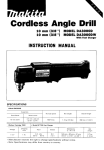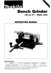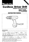
1
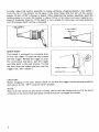
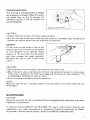
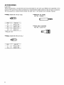
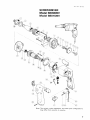
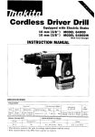
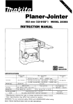
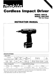
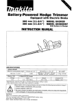
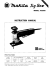
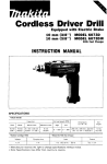
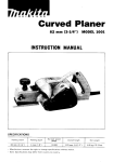
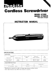
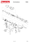
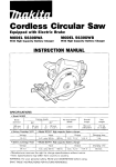
Drywall Screwdriver
MODEL 6800DBV
MODEL 680lDBV
INSTRUCTION MANUAL
DOUBLE
INSULATlON
SPECIFICAT10 NS
MODEL
68OODBV
6801DBV
Capacities
Drywall screws No. 6
Self drilling screw . . . 5 m m (3116“)
Bit shank
size
No load speed
(RPM)
114” Hex
0 - 2,500
114” Hex
0 - 4,000
Overall
length
Net
weight
’?fl!?y (i:zi:)
m
,::y’
* Manufacturer reserves t h e right t o change specifications w i t h o u t notice.
* Note: Specifications may differ from country t o country.
WARNING: For your personal safety, READ and UNDERSTAND before using.
SAVE THESE INSTRUCTIONS FOR FUTURE REFERENCE.
(i;z&
IMPORTANT
SAFETY INSTRUCTIONS
(For All Tools)
WARNING: WHEN USING ELECTRIC TOOLS, BASIC SAFETY
PRECAUTIONS SHOULD ALWAYS BE FOLLOWED TO REDUCE
THE RISK OF FIRE, ELECTRIC SHOCK, AND PERSONAL
INJURY, INCLUDING THE FOLLOWING:
READ ALL INSTRUCTIONS.
1. KEEP WORK AREA CLEAN. Cluttered areas and benches invite injuries.
2. CONSIDER WORK AREA ENVIRONMENT. Don't use power tools in damp
or wet locations. Keep work area well lit. Don't expose power tools t o rain.
Don't use tool in presence of flammable liquids or gases.
3. KEEP CHILDREN AWAY. All visitors should be kept away from work area.
Don't let visitors contact tool or extension cord.
4. STORE IDLE TOOLS. When not in use, tools should be stored in dry, and high
or locked-up place - out of reach of children.
5. DON'T FORCE TOOL. It will do the job better and safer at the rate for which
it was intended.
6. USE RIGHT TOOL. Don't force small tool or attachment t o do the job of a
heavy-duty tool. Don't use tool for purpose not intended; for example, don't
use circular saw for cutting tree limbs or logs.
7.DRESS PROPERLY. Don't wear loose clothing or jewelry. They can be caught
in moving parts. Rubber gloves and non-skid footwear are recommended
when working outdoors. Wear protective hair covering t o contain long hair.
8. USE SAFETY GLASSES. Also use face or dust mask if cutting operation is
dusty.
9. DON'T ABUSE CORD. Never carry tool by cord or yank it t o disconnect from
receptacle. Keep cord from heat, oil, and sharp edges.
IO. SECURE WORK.
Use clamps or a vise t o hold work. It's safer than using
your hand and it frees both hands t o operate tool.
11. DON'T OVERREACH. Keep proper footing and balance at all times.
12. MAINTAIN TOOLS WITH CARE. Keep tools sharp and clean for better and
safer performance. Follow instructions for lubricating and changing accessories. Inspect tool cords periodically and if damaged, have repaired by authorized service facility. Inspect extension cords periodically and replace if
damaged. Keep handles dry, clean, and free from oil and grease.
13. DISCONNECT TOOLS. When not in use, before servicing, and when changing accessories, such as blades, bits, cutters.
2
14. REMOVE ADJUSTING KEYS AND WRENCHES. Form habit of checking t o
see that keys and adjusting wrenches are removed from tool before turning
it on.
15. AVOID UNINTENTIONAL STARTING. Don't carry tool w i t h finger on switch.
Be sure switch is OFF when plugging in.
16. EXTENSION CORDS. Make sure your extension cord is in good condition.
When using an extension cord, be sure t o use one heavy enough t o carry
the current your product will draw. A n undersized cord will cause a drop
in line voltage resulting in loss of power and overheating. Table 1 shows the
correct size t o use depending on cord length and nameplate ampere rating.
If in doubt, use the next heavier gage. The smaller the gage number, the
heavier the cord.
TABLE 1
MINIMUM GAGE FOR CORD SETS
Total Length of Cord in Feet
0-25
I
26
- 50
Ampere Rating
More
Not More
Than
Than
0
6
10
12
-
6
10
12
16
I
51 - 100
I
101 - 150
1
14
AWG
18
18
16
14
16
16
16
12
;:
12
14
12
Not Recommended
3
VOLTAGE WARNING: Before connecting the tool t o a power source (receptacle,
outlet, etc.) be sure the voltage supplied is the same as that specified on the
nameplate of the tool. A power source w i t h voltage greater than that specified
for the tool can result in SERIOUS INJURY t o the user - as well as damage t o
the tool. If in doubt, DO NOT PLUG IN THE TOOL. Using a power source w i t h
voltage less than the nameplate rating is harmful t o the motor.
SAVE THESE INSTRUCTIONS.
ADDITIONAL SAFETY RULES
1. Always be sure you have a firm footing.
Be sure no one is below when using the tool in high locations.
2. Hold the tool firmly.
3. Keep hands away from rotating parts.
4. When driving into walls, floors or wherever ”live” electrical wires may be
encountered, DO NOT TOUCH ANY METAL PARTS OF THE TOOL!
Hold the tool only by the insulated grasping surfaces t o prevent electric shock
if you drive into a “live” wire.
5. Do not touch the bit or the workpiece immediately after operation: they may
be extremely hot and could burn your skin.
SAVE THESE INSTRUCTIONS.
4
Removing or installing locator assembly
To remove the locator assembly, pull the
locking sleeve forward and then turn it
counterclockwise.
To install the locator assembly, screw it
clockwise and then push the locking sleeve
back in lightly toward the motor. Turn the
locking sleeve slightly to match the locking
positions and then push in firmly to lock
the locator in place.
Locking position
Locking s l e e v e - y \
Locator A
Removing or installing bit
CAUTION :
Always be sure that the tool i s switched off and unplugged before removing or installing
bit.
After removing the locator assembly, pull
firmly to remove the magnetic bit holder.
Hold the magnetic bit holder in your hand
and grasp the bit with a pair of pliers. Pull
the bit out of the magnetic bit holder.
Sometimes, it helps to wiggle the bit with
the pliers as you pull.
Locator
Bit
Magnetic b i t holder
2
To install the bit, follow the removal procedures in reverse.
Depth adjustment
Pull the locking sleeve forward and then
turn it to adjust the depth.
Locator
Locking
Locking position
1
Gear housing
'
/ -
5
Initially, adjust the locator assembly to create a distance of approximately 1 mm (3/64")
from the tip of the locator t o the base of the screw head. One full turn of the locator
equals 1.5 mm (1/16") change in depth. After adjusting the locator assembly, push the
locking sleeve in to lock the locator in place. Drive a trial screw into your material or a
piece of duplicate material. If the depth i s not suitable for the screw, continue adjusting
until the proper depth setting is obtained.
1 mm
(3/64")
I
I
Switch action
Tool speed i s increased by increasing pressure on the trigger. To start the tool, simply
pull the trigger. Release the trigger to stop.
For continuous operation, pull the trigger
and then push in the lock button. To stop
the tool from the locked position, pull the
trigger fully, then release it.
I
I
Trigger switch
Lock button
I
CAUTION :
Before plugging in the tool, always check to see that the trigger switch actuates properly
and returns to the "OFF" position when released.
NOTE :
Even with the switch on and motor running, the bit will not rotate until you fit the point
of the bit in the screw head and apply forward pressure to engage the clutch.
6
Reversing switch action
This tool has a reversing switch to change
the direction of rotation. Move the reversing switch lever to the b position for
clockwise rotation or the 'g\ position for
counterclockwise.
Reversing switch lever
1
CAUTION :
Always check the direction of rotation before drilling.
.Use the reversing switch only when the tool comes to a complete stop. Changing the
direction of rotation before the tool stops may ruin the tool.
0
Operation
Fit the screw on the point of the bit and
place the point of the screw on the surface
of the workpiece to be fastened. Apply
pressure to the tool, S t a r t the tool slowly
and then increase the speed gradually.
Withdraw the tool as soon as the clutch
cuts in.
CAUTION :
Use the proper bit for the head of the screw that you wish to use.
0 When fitting the screw onto the point of the bit, be careful not to push in on the screw.
If the screw i s pushed in, the clutch will engage and the screw will rotate suddenly. This
could damage a workpiece or cause an injury.
0 Do not continue unnecessary clutching operation.
0
NOTE :
Make sure that the bit i s inserted straight in the screw head, or the screw and/or bit may
be damaged.
MAINTENANCE
CAUTION :
Always be sure that the tool is switched off and unplugged before attempting to perform
inspection or maintenance.
To maintain product SAFETY and RELIABILITY, reparis, carbon brush inspection and
replacement, any other maintenance or adjustment should be performed by Makita
Authorized or Factory Service Centers, always using Makita replacement parts.
7
ACCESSORIES
CAUTION:
These accessories or attachments are recommended for use w i t h your Makita tool specified in this
manual. The use of any other accessories or attachments might present a risk of injury t o persons.
The accessories or attachments should be used only in the proper and intended manner.
Phillips insert bit (10 per pkg.)
Part No.
Size
#2
*#2
I
I
#3
784211-2A
784211-6
78421 3-A
Phillips insert bit ( 5 0 per pkg.)
Size
#1
#2
8
Magnetic bit holder
Part No. 7 8 4 8 0 1 - 1
I
I
Part
NO.
784212-OB
78421 1-28
Nose piece assembly
Part No. 1 2 2 2 1 1 - 8
Jun -07-’93
US
SCREWDRIVER
Model 6800DBV
Model 680 1DBV
Note: The switch, noise suppressor and other part configuratlons
may differ from country to country.
9
Jun - 0 7 - ' 9 3
MODEL 6800DBV. 6 8 0 1 0 B V
IF,',"
1
2
3
4
5
6
7
8
9
10
11
12
13
14
15
16
17
18
19
20
22
23
24
z&
DESCRIPTION
1
1
1
1
2
1
1
1
1
1
1
1
1
1
1
1
1
2
1
1
1
2
1
Fell Cover
Felt Ring 3 0
"0"
&tD
DESCRIPTION
25
26
1
1
27
1
28
1
Localor
Locking Sleeve
Pan Head Screw M 4 x 5 5 i W i t h Washerl
0 Ring 27
ea, tiouslng
Leaf spmy
Steel Ball 3 5
Spindle
Compresslo" Sprlny 9
Thin Washer 8
Helical Gear
56 For Model 6800DBV
37 For Model 6801DBV
Woodruff K e y 3
Gear S h a l t
Thrust Needle Bearing 1 0 2 3
Name Plate
Rivet 0 5
Pan Head Screw M 4 x 4 5 i W i l h Washerl
Hook
Rubber Pin 4
Pan Head Screw M 4 x 5 0 IWith Washerl
Gear Housinq Cover
29
30
31
32
33
34
36
37
38
39
41
43
44
45
46
47
48
49
1
1
I
2
2
2
1
1
1
3
1
2
1
1
1
1
1
1
- -
Note The s w i t c h and other part specifications may d i f f e r from country 10 c o u n t r y
10
Rubber Pin 4
Ball Bearlrlq
627LB For Model 68OODBV
608LB For Model 6801DBV
Fan 58
ARMATURE ASSEMBLY
i W i t h Item 2 6
291
Ball Bearing 627LB
Baffle Plate
FIELD ASSEMBLY
Brush Holder
Carbon Brush
Pan Head Screw M 4 x 1 4 i W i t h Washer1
Switch
Switch Cover
Handle Cover
Pari Head S c w w M 4 x 2 8 IWifh Washer1
Swilch
Pan Head Screw M 4 x 1 8 IWith Washcrl
Strairi Relief
Cord
Cord G u a r d
Motor Housing
Sponge Wasl?er 11
l n s ~ l a f i ~Washer
n
US
MAKITA LIMITED ONE YEAR WARRANTY
Warranty Policy
Every Makita tool is thoroughly inspected and tested before leaving the factory. It is warranted to
be free of defects from workmanship and materials for the period of ONE YEAR from the date of
original purchase. Should any trouble develop during this one-year period, return the COMPLETE
tool, freight prepaid, t o one of Makita’s Factory or Authorized Service Centers. If inspection shows
the trouble is caused by defective workmanship or material, Makita will repair (or at our option,
replace) without charge.
This Warranty does not apply where:
repairs have been made or attempted by others:
repairs are required because of normal wear and tear:
e The tool has been abused, misused or improperly maintained;
e alterations have been made t o the tool.
IN NO EVENT SHALL MAKITA BE LIABLE FOR ANY INDIRECT, INCIDENTAL OR CONSEQUENTIAL DAMAGES FROM THE SALE OR USE O F THE PRODUCT. THIS DISCLAIMER
APPLIES BOTH DURING AND AFTER THE TERM O F THIS WARRANTY.
MAKITA DISCLAIMS LIABILITY FOR ANY IMPLIED WARRANTIES, INCLUDING IMPLIED
WARRANTIES O F “MERCHANTABILITY” AND “FITNESS FOR A SPECIFIC PURPOSE,
AFTER THE ONE-YEAR TERM O F THIS WARRANTY.
This Warranty gives you specific legal rights, and you may also have other rights which vary from
state t o state. Some states do not allow the exclusion or Limitation of incidental or consequential
damages, so the above limitation or exclusion may not apply t o you. Some states do not allow
limitation on how long an implied warranty lasts, so the above limitation may not apply t o YOU.
Makita Corporation
3-11-8, Sumiyoshi-cho,
Anjo, Aichi 446 Japan
883050C060
PRINTED IN JAPAN
1995 - 4 - N