1
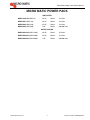
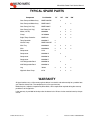
MICRO MATIC POWER PACK
Service Manual
Release Date: February 6, 2004
Publication Number: 620920804SER
Revision Date: NA
Revision: A
Micro Matic Power Pack Service Manual
TABLE OF CONTENTS
Micro Matic Power Pack . . . . . . . . . . . . . . . . . . . . . . . . . . . . . . . . . . . . . . . . . . . . . . . . 1
Equipment Specifications . . . . . . . . . . . . . . . . . . . . . . . . . . . . . . . . . . . . . . . . . . . . . . . 2
Cooling distance: . . . . . . . . . . . . . . . . . . . . . . . . . . . . . . . . . . . . . . . . . . . . . . . . . . . . 2
Installation and Operation. . . . . . . . . . . . . . . . . . . . . . . . . . . . . . . . . . . . . . . . . . . . . . .
75’ Unit. . . . . . . . . . . . . . . . . . . . . . . . . . . . . . . . . . . . . . . . . . . . . . . . . . . . . . . . . . . .
125’, 250’, and 500’ Units . . . . . . . . . . . . . . . . . . . . . . . . . . . . . . . . . . . . . . . . . . . . .
Electronic Temperature Control with Display . . . . . . . . . . . . . . . . . . . . . . . . . . . . . . .
3
3
3
4
Maintenance . . . . . . . . . . . . . . . . . . . . . . . . . . . . . . . . . . . . . . . . . . . . . . . . . . . . . . . . . . 4
Troubleshooting. . . . . . . . . . . . . . . . . . . . . . . . . . . . . . . . . . . . . . . . . . . . . . . . . . . . . . . 5
Typical Spare Parts . . . . . . . . . . . . . . . . . . . . . . . . . . . . . . . . . . . . . . . . . . . . . . . . . . . . 7
Warranty . . . . . . . . . . . . . . . . . . . . . . . . . . . . . . . . . . . . . . . . . . . . . . . . . . . . . . . . . . . . . 7
© 2004, IMI Cornelius Inc.
Publication Number: 620920804SER
Micro Matic Power Pack Service Manual
MICRO MATIC POWER PACK
AIR COOLED
MMPP-4301-EP (GBC-75)
1/3 HP
R134a
115 Volts
MMPP4301 (GBC-125)
1/3 HP
R134a
115 Volts
MMPP4302 (GBC-250)
1/2 HP
R134a
115 Volts
MMPP4305 (GBC-500)
1 HP
R134a
208/230 Volts
WATER COOLED
MMPP4301-WC (GBC-125W)
1/3 HP
R134a
115 Volts
MMPP4302-WC (GBC-250W)
1/2 HP
R134a
115 Volts
MMPP4305-WC (GBC-500W)
1 HP
R134a
208/230 Volts
© 2004, IMI Cornelius Inc.
-1-
Publication Number: 620920804SER
Micro Matic Power Pack Service Manual
EQUIPMENT SPECIFICATIONS
COOLING DISTANCE:
MMPP4301-EP
UP TO 75’ of trunk line
MMPP4301 and MMPP4301-WC
UP TO 125’ of trunk line
MMPP4302 and MMPP4302-WC
UP TO 250’ of trunk line
MMPP4305 and MMPP4305-WC
UP TO 500’ of trunk line
Model
Part Number
75’
MMPP4301-EP
125’
250’
500’
MMPP4301/
MMPP4301WC
MMPP4302/
MMPP4302WC
MMPP4305/
MMPP4305WC
Voltage
115
115
115
208/230
Start up
9.5A
12.8A
13.6A
7.5A
Running
7.2A
10.1A
10.9A
5.3A
Refrigerant
R134a
R134a
R134a
R134a
Charge
10.5 oz.
10.5 oz.
12 oz.
20 oz.
Pressure
100 (low)
100 (low)
100 (low)
100 (low)
360 (high)
360 (high)
360 (high)
360 (high)
H: 22
H: 32
H: 32
H: 37
W: 20
W: 18
W: 18
W:18
D: 24
D: 26
D: 26
D: 26
90 lbs.
110 lbs.
130 lbs.
155 lbs.
Dimensions (inches)*
Weight
* Dimensions include pump and motor
Tank capacity
5 gal.
11.5 gal.
11.3 gal.
11.5 gal.
2-part Injection Foam Insulation
1”
1”
1”
1”
75’ Unit:
Submerged vertical pump with capacity of 60 GPH. No priming
required.
125’, 250’, and 500’ Units:
Gear pump with capacity of 80 GPH gravity fed to insure longer pump
life.
Publication Number: 620920804SER
-2-
© 2004, IMI Cornelius Inc.
Micro Matic Power Pack Service Manual
INSTALLATION AND OPERATION
1. Remove packaging from the unit in the vicinity of the area where it will be installed.
2. Carefully lift the unit into the desired position.
NOTE: DO NOT PUSH UNIT - damage will be caused to the legs if the unit is pushed into position.
75’ UNIT
1.
2.
3.
4.
5.
6.
7.
8.
9.
Connect one of the glycol tubes to the pump outlet. Insulate any exposed tubing.
Connect the second glycol line to the pump outlet. Insulate any exposed tubing.
Carefully push the glycol bath lid to one side, allowing sufficient space to fill the bath with liquid.
Inspect the bath for debris.
Fill the glycol bath with Micro Matic Polar Flo glycol solution (mixed 2 ½ parts water to 1 part glycol). Fill the bath to the fill level on the glycol level indicator.
Connect unit to the electrical outlets capable of handling the required voltage loads. This should be
carried out by suitably trained personnel and comply with all state and national electrical codes.
Glycol level will fall as glycol is pumped through the glycol lines. Continue to fill the bath to the fill
level on the glycol level indicator.
Replace top cover.
Inspect for any leaks.
125’, 250’, AND 500’ UNITS
1. Remove the refrigeration deck from the unit.
2. Inspect the glycol tank for any debris.
3. Connect one of the glycol lines from the beer python to the pump outlet. Insulate any exposed tubing.
NOTE: In units with more than one pump, connect a glycol line to each pump outlet.
4.
5.
6.
7.
8.
9.
Connect the second glycol line from each circuit to the glycol bath inlet.
Fill the glycol bath with Micro Matic Polar Flo glycol solution (mixed 2 ½ parts water to 1 part glycol). Fill bath to the level of the fill line on the glycol level indicator.
Replace the refrigeration deck.
Connect the unit to the electrical outlets capable of handling the required voltage loads. This should
be carried out by suitably trained personnel and must comply with all state and national codes.
Glycol level will fall as glycol is pumped through the glycol lines. Continue to fill the bath to the fill
level on the glycol level indicator.
Inspect for any leaks.
10. Temperature of the glycol outlet will drop slowly to 30oF.
NOTE: To adjust the glycol temperature please see Adjusting the Electronic Thermostat.
© 2004, IMI Cornelius Inc.
-3-
Publication Number: 620920804SER
Micro Matic Power Pack Service Manual
ELECTRONIC TEMPERATURE CONTROL WITH DISPLAY
NOTE: When the unit leaves the factory the electronic thermostat is pre-set to the following
parameters:
Temperature Scale:
Setpoint:
Differential:
F (Farenheit)
30oF
3oF
Operating Mode:
C1 (Cooling)
NOTE: To ensure the correct operation of your unit these parameters must be adhered to.
NOTE: The Keypad Lockout switch must be in the “UNLOCK” position (factory setting) before
adjusting the control. If the keypad is locked, pressing buttons has no effect on the control. The
Keypad Lockout switch is located on the back inside of the front cover. If necessary, remove the
cover by loosening the four captive cover screws.
Changing Temperature Units
1.
2.
3.
Press Set button once to display temperature unit.
Press the Up or Down button to toggle between °F and °C.
Continue pressing and releasing Set button until tank temperature is displayed in normal operating
mode (“S1” not flashing).
Setting the Setpoint
Before setting the setpoint, be sure the control is set to the temperature units you want to use, Celsius or
Fahrenheit.
To view and adjust the setpoint, use the following method:
1.
2.
3.
Press the Set button twice to display Setpoint (“S1” flashing).
Press the Up or Down button to adjust Setpoint.
Continue pressing and releasing Set button until tank temperature is displayed in normal operating
mode (“S1” not flashing).
NOTE: If no entries are made for thirty (30) seconds, the control reverts back to the tank temperature display.
MAINTENANCE
1.
2.
3.
4.
5.
6.
7.
8.
Inspect the unit monthly to ensure that the glycol level is maintained to the fill level.
If the level is low replace with a Micro Matic Polar Flo glycol solution, (mixed 2 ½ parts water to 1
part glycol).
If there is evidence of ice build up in the unit, allow the ice to melt and replace all the water/glycol
solution with a fresh solution.
The glycol/water solution should be changed every 2 years. In regions of high humidity considerations should be given to replacing the solution on an annual basis.
Check and clean the condenser fins every 6 months.
Check that there is adequate air flow through the unit ensuring enough space all around and that
there are no obstructions in front of the air flow vents.
Check the condition and effectiveness of the trunk line insulation.
At regular intervals, to be determined by the owner, the unit should be checked for electrical safety.
Publication Number: 620920804SER
-4-
© 2004, IMI Cornelius Inc.
Micro Matic Power Pack Service Manual
TROUBLESHOOTING
Trouble
1.
2.
3.
4.
Cause
Solution
A.
Warm walk-in cooler
A.
Adjust cooler temperature to
34° to 36°F (use quality thermometer)
B.
Check applied pressure to
barrel
B.
Adjust setting on regulator for
proper pressure
C.
Check equipment
C.
Check the physical equipment from keg to faucet
D.
Warm product lines
D.
Refer to 5
A.
Compressor relay or capacitor malfunction
A.
Replace compressor relay,
relay or capacitor.
B.
Inadequate voltage
B.
Measure voltage across
common and run terminal on
compressor. Voltage must
not drop below 90% of rated
voltage.
C.
Compressor failure
C.
Replace compressor.
Compressor
starts and continues to run until
freeze up and
will not cut off.
A.
Thermostat control failure
A.
Replace thermostat
B.
Freon leak
B.
Repair leak and recharge
Compressor
does not run but
hums.
A.
Inadequate voltage
A.
Measure voltage across
common and run terminal on
compressor. Voltage must
not drop below 90% of rated
voltage
B.
Starting relay malfunction
B.
Replace starting relay
Be sure to use correct relay.
Failure to use correct relay
will cause compressor failure.
C.
Compressor malfunction
C.
Replace compressor
Excessive foam
Compressor
does not start
(no hum), but the
fan motor runs.
© 2004, IMI Cornelius Inc.
-5-
Publication Number: 620920804SER
Micro Matic Power Pack Service Manual
5.
Warm beer
A.
Defective Pump (check
motor also)
A.
Check return line in reservoir
for liquid flow. Replace pump
B.
Defective motor (check pump
also)
B.
Replace motor
C.
Refrigeration unit not running
C.
Refer to 2
D.
Conduit lines located in overheated area
D.
Remove from any hot water
pipes or kitchen area with
stove or glass washer.
E.
Conduit lines flooded in PVC
E.
Remove lines from PVC,
thoroughly dry PVC and
repair or replace conduit as
needed.
chase.
Publication Number: 620920804SER
F.
Uninsulated or poorly insulated lines
F.
All lines should be fully insulated from cooler into dispenser. Includes glycol lines
from power pack into cooler.
G.
Thermostat
G.
Adjust temperature to colder
setting.
H.
Condenser fan motor not
working
H.
Replace condenser fan
motor.
I.
Freon leak
I.
Repair leak and recharge.
J.
Dirty condenser
J.
Clean the condenser
K.
Condensation inside conduit
insulation (may be caused
from cleaning lines)
K.
Check trunk housing in areas
for drooping or low spots,
split insulation approximately 5” and separate.
Allow any water to drain,
then air dry, the seal closed.
L.
Warm walk in cooler
L.
Check temperature of walk-in
cooler-liquid temperature, set
cooler at 36° to 38°.
-6-
© 2004, IMI Cornelius Inc.
Micro Matic Power Pack Service Manual
TYPICAL SPARE PARTS
Component
Part Number
75’
125’
250’
500’
x
x
x
x
Gear Pump and Motor Assy
MMPP4301PM
x
Gear Pump and Motor Assy
MMPP4301-P
Gear Pump (Incl. Key)
MMPP4302-P
Gear Pump (Incl. Key)
MPP4301-M
Motor (1/3 HP)
63030058
x
x
x
Clamp
187483000
x
x
x
Digital Temp Controller
MMPP012
x
x
x
Temp Controller
620202617
x
Vertical Pump
MMPP4201-MP
x
Wick Tray
620202634
x
x
x
x
Wick
620202633
x
x
x
x
Compressor
2129
x
Compressor
620202815
Compressor
620202816
Compressor
620202817
125’ Refrigeration Deck
620202818
250’ Refrigeration Deck
620202819
Leg
70439
Nipple for Gear Pump
6170
x
x
x
x
x
x
x
x
x
x
x
x
x
WARRANTY
All glycol coolers carry a full warranty against defects in materials and workmanship for a period of one
year from the date of sale. The compressor has a five year warranty.
Defective parts, subject to inspection by Micro Matic, will be replaced or repaired during the warranty
period on a no charge basis.
Labor warranty is provided for 90 days after the date of sale. All loss of sales must be borne by the purchaser.
© 2004, IMI Cornelius Inc.
-7-
Publication Number: 620920804SER
Micro Matic Power Pack Service Manual
Publication Number: 620920804SER
-8-
© 2004, IMI Cornelius Inc.
19791 Bahama Street
Northridge, CA 91324
Northeast
4601 Saucon Creek Road
Center Valley, PA 18034
(610) 625-4464
(610) 625-4466 (Fax)
Southeast
16121 Flight Path Drive
Brooksville, FL 34604
(352) 799-6331
(352) 796-2629 (Fax)
Central
10726 North Second Street
Machesney, IL 61115
(815) 968-7557
(815) 968-0363 (Fax)
West
19779 Bahama Street
Northridge, CA 91324
(818) 701-9765
(818) 701-9844 (Fax)