1
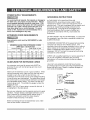
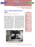
Operator's Manual
I ,,o,:,:ss ""'i
4,4 liP (Max. Developed)
10" Inch Blade
4000 R.P.M.
JOB SITE TABLE SAW
Model No.
137.218300
CAUTION:
Before using this Table Saw,
read this manual and follow
all its Safety Rules and
Operating Instructions
•
•
•
•
•
Customer
Help
1-800-843-1682
Safety Instructions
Installation
Operation
Maintenance
Parts List
Line
Sears, Roebuck and Co., Hoffman Estates, IL 60179 USA
Visit our Craftsman website: www.sears.com/craftsman
Part No. 13721830001
SECTION
PAGE
Warranty ........................................
Product Specifications .......................
Power Tool Safety ............................
Table Saw Safety ..............................
Electrical Requirements and Safety ......
Accessories and Attachments ..............
Tools Needed For Assembly ................
Carton Contents ..............................
Know Your Table Saw .......................
2
2
3
4
5
6
6
6
8
SECTION
PAGE
Glossary of Terms ...........................
Assembly and Adjustments .................
Operation .......................................
Maintenance ...................................
Troubleshooting Guide .......................
Push Stick Pattern .............................
Parts List .........................................
9
10
17
21
22
23
24
FULL ONE YEAR WARRANTY
If this Table Saw fails due to a defect in material or workmanship
Sears will at its option repair or replace it free of charge.
within one year of date of purchase,
Return this Table Saw to a Sears Service Center for repair, or to place of purchase
for replacement.
This warranty gives you specific legal rights, and you may also have other rights which may vary from
state to state.
Sears, Roebuck and Co., Dept. 817 WA, Hoffman Estates, IL 60179
IAWARNING
I
Some dust created by power sanding, sawing, grinding, drilling and other construction activities contains
chemicals known to the state of California to cause cancer, birth defects or other reproductive harm. Some
examples of these chemicals are:
• Lead from lead-based paints
• Crystalline silica from bricks, cement and other masonry products
° Arsenic and chromium from chemically treated lumber
Your risk from these exposures varies, depending on how often you do this type of work. To reduce your
exposure to these chemicals work in a well-ventilated area and work with approved safety equipmentsuch as
dust masks that are spec a y des gned to f ter out m croscop c part c es.
MOTOR
HP (Maximum developed) .....
Type ..................................
Amps .................................
Voltage ..............................
Hz ......................................
RPM (no load) ......................
Overload Protection .............
4.4
Universal
15
120
60
4000
YES
SAW
Table Size ........................
Table Extensions ...............
Extension Fence Capacity...
Blade Size ........................
Rip Scale .........................
Rip Fence ........................
Miter Gauge ......................
Maximum Cut Depth @ 90°..
Maximum Cut Depth @ 45°..
Maximum Dado Cut Width...
Net Weight ......................
24" x 21"
Right & Rear
24-1/2" Right
10"
YES
YES
YES
3-1/8"
2-1/4"
13/16"
98 LBS
IA WARNINGI
To avoid electrical hazards, fire hazards or damage to the table saw, use proper circuit protection.
This table saw is wired at the factory for 110-120 Volt operation. It must be connected to a 110-120 Volt / 15
Ampere time delay fuse or circuit breaker. To avoid shock or fire, replace power cord immediately if it is worn,
cut or damaged in any way.
Before using your table saw, it is critical that you read and understand these safety rules. Failure to follow
these rules could result in serious injury to you or damage to the table saw.
Before using your table saw, it is critical that you read and understand these safety rules.
Failure to follow these rules could result in serious injury or damage to the table saw.
Good safety practices are a combination of common
sense, staying alert and understanding how to use your
power tool. To avoid mistakes that could cause serious
injury, do not plug in your power tool until you have read
and understood the following safety rules:
1.
READ and become familiar with this entire
Operator's Manual. LEARN the tool's applications,
limitations and possible hazards.
,
.
,
,
15 REMOVE ADJUSTING KEYS AND WRENCHES.
Form the habit of checking to see that keys and
adjusting wrenches are removed from the tool
before turning ON.
16 NEVER LEAVE TOOL RUNNING UNATTENDED.
TURN THE POWER "OFF". Do not leave the tool
before it comes to a complete stop.
17 NEVER STAND ON TOOL. Serious injury could
occur if the tool is tipped or if the cutting tool is
unintentionally contacted.
Look for this symbol that identifies important
safety precautions. It means CAUTION!
BECOME ALERT! YOUR SAFETY IS INVOLVED!
18 DO NOT OVERREACH. Keep proper footing and
balance at all times.
NEVER OPERATE THIS MACHINE WITHOUT THE
SAFETY GUARD IN PLACE FOR ALL THROUGH
SAWING OPERATIONS.
19. MAINTAIN TOOLS WITH CARE. Keep tools sharp
and clean for most efficient and safest performance.
Follow instructions for lubricating and changing
accessories.
DO NOT USE IN A DANGEROUS ENVIRONMENT
such as damp or wet locations or exposure to rain.
Keep work area well lighted.
DO NOT use power tools in the presence of
flammable liquids or gases.
6.
KEEP WORK AREA CLEAN. Cluttered areas and
benches invite accidents.
7.
KEEP CHILDREN AWAY. All visitors should be
kept at a safe distance from the work area.
8.
DO NOT FORCE THE TOOL. It will do the job
better and safer at the rate for which it was designed.
9.
USE THE RIGHT TOOL. Don't force the tool or
attachment to do a job for which it is not designed.
20. CHECK FOR DAMAGED OR LOOSE PARTS.
Before further use of the tool, a guard or other part
that is damaged should be carefully checked to
ensure it will operate properly and perform its
intended function. Check for alignment of moving
parts, loose binding of moving parts, mounting and
any other conditions that may affect its safe
operation. A guard or other part that is loose or
damaged should be properly adjusted repaired or
replaced.
21. MAKE WORKSHOP CHILD PROOF with padlocks,
master switches or by removing starter keys.
22. DO NOT operate the tool if you are under the
influence of any drugs, alcohol or medication that
could impair your ability to use the tool safely.
10. WEAR PROPER APPAREL DO NOT wear loose
clothing, gloves, neckties, rings, bracelets or other
jewelry that may get caught in moving parts. Nonslip footwear is recommended. Wear protective hair
covering to contain long hair.
23. USE DUST COLLECTION SYSTEM wherever
possible. Dust generated from certain materials can
be hazardous to your health and in some cases, a
fire hazard. Always operate the power tool in a wellventilated area with adequate dust removal.
11. WEAR A FACE MASK OR DUST MASK. Sawing,
cutting and sanding operations produce dust.
24. ALWAYS WEAR EYE PROTECTION. Any power
tool can throw foreign objects into your eyes that
could cause permanent eye damage. ALWAYS wear
safety goggles (not glasses) that comply with ANSI
safety standard Z87. t. Everyday glasses have only
impact resistant lenses. They ARE NOT safety
glasses.
NOTE: Glasses or goggles not in compliance with
ANSI Z87.1 could cause serious injury when they
break.
12. DISCONNECT TOOLS before servicing and when
changing accessories such as blades, cutters, etc.
13. REDUCE THE RISK OF UNINTENTIONAL
STARTING. Make sure the switch is in the OFF
position before plugging into the power supply.
14. USE ONLY RECOMMENDED ACCESSORIES.
Consult the Operator's Manual for recommended
accessories. The use of improper accessories may
cause injury to you or damage to the tool.
25. DIRECTION OF FEED. Feed work into a blade or
cutter against the direction of rotation of the blade or
cutter only.
,
2.
,
,
5.
12. PROVIDE ADEQUATE SUPPORT to the rear and
the sides of the saw table for long or wide workpieces.
ALWAYS USE SAW BLADE GUARD, splitter and
anti-kickback pawls for every operation for which they
can be used, including through sawing. Through
sawing operations are those in which the blade cuts
completely through the workpiece when ripping or
crosscutting.
13. AVOID KICKBACKS (work thrown back towards you)
by keeping the blade sharp, the rip fence parallel to
the saw blade and by keeping the splitter, antikickback pawls and guards in place, aligned and
functioning. Do not release work before it has
passed all the way past the saw blade. Do not rip
work that is twisted, warped or does not have a
straight edge to guide it along the fence.
ALWAYS HOLD WORK FIRMLY against the miter
gauge or rip fence,
USE A PUSH STICK when required. Always use a
push stick especially when ripping narrow stock.
Refer to ripping instructions in this Operator's Manual
where the push stick is covered in detail. A pattern for
making your own push stick is included on page 23.
14, AVOID AWKWARD OPERATIONS and hand
positions where a sudden slip could cause your hand
to move into the saw blade.
NEVER PERFORM ANY OPERATION "FREE
HAND", which means using only your hands to
support or guide the workpiece. Always use
either the fence or the miter gauge to position
and guide the work.
15, NEVER USE SOLVENTS to clean plastic parts.
Solvents could possibly dissolve or otherwise
damage the material. Only a soft damp cloth should
be used to clean plastic parts.
WARNING: FREEHAND CUTTING IS THE MAJOR
CAUSE OF KICK-BACK & FINGER/HAND
AMPUTATIONS.
16, MOUNT your table saw on a bench or stand before
performing any cutting operations. Refer to
ASSEMBLY AND ADJUSTMENTS on page 10.
17, NEVER CUT METALS or materials which may make
hazardous dust.
NEVER STAND or have any part of your body in line
with the path of the saw blade. Keep your hands out
of the saw blade path.
6.
NEVER REACH behind or over the cutting tool for
any reason,
7.
REMOVE the rip fence when crosscutting.
8.
DO NOT USE a molding head with this saw.
9.
FEED WORK INTO THE BLADE against the
direction of rotation only.
18, ALWAYS USE IN WELL-VENTILATED AREA.
Remove sawdust frequently. Clean out sawdust from
the interior of the saw to prevent a potential fire
hazard. Attach a vacuum to the dust port for
additional sawdust removal.
19, NEVER LEAVE THE SAW running unattended. Do
not leave the saw until it comes to a complete stop.
20, For proper operation follow the instructions in this
Operator's Manual entitled ASSEMBLY AND
ADJUSTMENTS (Page 10). Failure to provide
sawdust fall-through and removal hole will allow
sawdust to build up in the motor area resulting in a
fire hazard and potential motor damage.
10. NEVER use the rip fence as a cut-off gauge when
crosscutting.
11, NEVER ATTEMPT TO FREE A STALLED SAW
BLADE without first turning the saw OFF. Turn
power switch OFF immediately to prevent motor
damage.
4
POWER SUPPLY
REQUIREMENTS
GROUNDING
To avoid electrical hazards, fire hazards or damage to
the table saw, use proper circuit protection. Always
use a separate electrical circuit for your tools. This
power tool is wired at the factory for 120V operation.
Connect it to a 120V, 15 Amp circuit and use a 15
Amp time delay fuse or circuit breaker. To avoid
shock or fire, replace the cord immediately if it is
worn, cut or damaged in any way.
EXTENSION
IN THE EVENT OF A MALFUNCTION OR
BREAKDOWN, grounding provides a path of least
resistance for electric current and reduces the risk of
electric shock. This saw is equipped with an electric cord
that has an equipment grounding conductor and a
grounding plug. The plug MUST be plugged into a
matching receptacle that is properly installed and
grounded in accordance with ALL local codes and
ordinances.
CORD REQUIREMENTS
Any extension cord must be GROUNDED for safe
operation.
MINIMUM GAUGE FOR EXTENSION CORDS
(AWG type / 120 Volt only)
Ampere Rating
Total length in _et
Not
More Than
More Than
25'
50'
100'
150'
0
6
18
16
16
14
6
10
18
16
14
12
10
12
16
16
14
12
GUIDELINES
INSTRUCTIONS
FOR EXTENSION
CORDS
Any extension cord used for power tools MUST be
grounded (3-wire with two flat prongs and one round
ground prong).
DO NOT MODIFY THE PLUG PROVIDED. If it will not fit
the receptacle, have the proper receptacle installed by a
qualified electrician.
IMPROPER CONNECTION of the equipment grounding
conductor can result in risk of electric shock. The
conductor (wire) with the green insulation (with or without
yellow stripes) is the equipment grounding conductor. If
repair or replacement of the electric cord or plug is
necessary, DO NOT connect the equipment grounding
conductor to a live terminal.
CHECK with a qualified electrician or service personnel if
you do not completely understand the grounding
instructions, or if you are not sure the saw is properly
grounded.
Use only 3-wire extension cords that have 3-prong
grounding plugs and 3-pole grounding receptacles that
accept the saw's plug. Repair or replace damaged or
worn cords immediately.
Make sure the extension cord is in good condition. When
using an extension cord, make sure you use one heavy
enough to carry the current the tool will draw. An
undersized cord will cause a drop in line voltage resulting
in loss of power and overheating. The table above shows
the correct size to use according to extension cord length
and nameplate ampere rating. If in doubt, use the next
heavier gauge cord. The smaller the gauge number the
heavier the cord.
NOTE: The 12 to 16 amp rating is correct for this tool. It
is highlighted in the table above.
3-Prong Plug
Grounding Lug
Be sure your extension cord is properly wired and in good
condition. Always replace a damaged extension cord or
have it repaired by a qualified person before using it.
Protect your extension cords from sharp objects,
excessive heat and damp or wet areas.
Before connecting the saw to the extension cord, make
sure the saw switch is turned OFF.
_l==q t
_(_.,,..-_-- Make Sure This
l_r_
_f'f'f'f'f'f'f'f'f'_
_
_,lt _
--
1I is Connected to a
I _j
_-,-_A%ter_ _
- Known Ground
I[_ 2*Prong
Receptacle
RECOMMENDED
ACCESSORIES
Visit your Sears Hardware Department or see the
Craftsman Power and Hand Tools Catalog to purchase
recommended accessories for this power tool.
To avoid the risk of personal injury:
• Do not use a dado with a diameter larger than 8".
• Maximum dado width is 13/16". DO NOT USE WIDER
COMBINATIONS.
• Do not use molding head set with this saw.
• Do not modify this power tool or use accessories not
recommended by Sears.
TOOLS
Medium
#2 Phillips
NEEDED
screwdriver
wrench
Combination
square
screwdriver
Straight
4mm
Adjustable
edge
Hex wrench
5mm Hex wrench
UNPACKING
AND CHECKING
CONTENTS
Separate all parts from packing materials. Check each part
with the illustration on the next page and the "Table of
Loose Parts" to make certain all items are accounted for,
before discarding any packing material.
If any part is missing or damaged, do not attempt to
assemble the table saw, plug in the power cord, or turn the
switch ON until the missing or damaged part is obtained
and is installed correctly.
TABLE OF LOOSE PARTS
ITEM
A.
B.
C.
D.
E.
F.
G.
H.
I.
J.
K.
L.
M.
N.
O.
P.
Q.
R,
DESCRIPTION
Table saw assembly
Rear table extension
Rear table extension tube
Location seat
Blade guard and splitter
Rubber Pad & screw
Rip fence
Dado table insert
Miter gauge
Push stick
Blade wrench
Push stick storage
Blade
Knob & flat washer
Handwheel handle
Hex. wrenches
Washers
QUANTITY
1
1
2
4
1
1 each
1
1
1
1
1
1
1
1 each
1
2
4
STAND
Stand assembly
Hex head bolts & flat washers
1
4
17mm Hex wrench
NOTE: To make assembly easier, keep contents of box together.
Apply a coat of automobile
wax to the table. Wipe all parts
thoroughly with a clean dry cloth. This will reduce friction when
pushing the workpiece.
UNPACKING
YOUR JOB SITE TABLE SAW
C
A
E
%
k
G
'----"
N
0
Q
__..J
_._,_
_-__"-_
Blade Guard
Hand hold
Miter Gauge
Rip Fence
Hand hold
Blade elevation
handwheel
Blade
tilt pointer
Blade
Blade
Overload
switch
Stand
bevel
lock knob
tilt scale
reset
Stand wheel
handle
Stand
ON/OFF
switch
latch
Stand buckle
with key
Leg stand
Stand latch
\
Table
Insert
Table
SideTable
Extension
Rear scale pointer
Rear extension
table
Rip fence and miter
gauge storage
Mounting
8
holes
CRAFTSMAN PROFESSIONAL
TABLE SAW TERMS
CROSSCUT - A cut made across the width of the
workpiece.
MITER GAUGE - A guide used for crosscutting
operations that slides in the tabletop channels located
on either side of the blade. It helps make accurate
straight or angle cuts.
FREEHAND - Performing a cut without using a fence
(guide), hold down or other proper device to prevent
the workpiece from twisting during the cutting
operation.
RIP FENCE - A guide used for rip cutting that clamps
to the tabletop. It allows the workpiece to be straight.
GUM - A sticky sap from wood products.
HEEL - Misalignment of the blade.
TABLE INSERT - Provides access to the blade arbor
for changing blades.
OVERLOAD RESET SWITCH - Resets the
thermocouple and provides a way to restart the saw
motor if it overheats or overloads.
BLADE BEVEL SCALE - Measures the angle the
blade is tilted when set for a bevel cut.
TABLE SCALE - Measures the distance the rip fence
is set from the blade, allowing quick setups.
ANTI-KICKBACK PAWLS - Prevents the workpiece
from being kicked upward or back toward the front of
the table saw by the spinning blade.
SPLITTER - Keeps the workpiece spread apart after
being cut, to prevent binding on the blade and
workpiece.
BLADE ELEVATION HANDWHEEL - Raises and
lowers the blade.
KERF - The amount of material removed by a blade
cut.
MITER CUT - An angle cut made across the width of
the workpiece.
RESIN - A sticky sap that has hardened.
REVOLUTIONS PER MINUTE (RPM) - The number
of turns completed by a spinning object in one minute.
SAW BLADE PATH - The area of the workpiece or
table top directly in line with the travel of the blade or
the part of the workpiece that will be cut.
SET - The distance between two saw blade tips, bent
outward in opposite directions to each other. The
further apart the tips are, the greater the set.
WORKPIECE - The item being cut. The surfaces of a
workpiece are commonly referred to as faces, ends
and edges.
BLADE TILTING HANDWHEEL - Tilts the blade to
any angle between 0 ° to 45 ° for bevel cuts.
WOODWORKING
TERMS
ARBOR - The shaft on which a blade is mounted.
Leadin
Kerf
Edge
Sawblade Path
Surface
BEVEL CUT - An angle cut made through the face of
the workpiece.
COMPOUND CUT - A simultaneous bevel and miter
cut.
Trailing Edge
ASSEMBLE THE TABLE SAW TO THE STAND
(FIG. B)
1. Release the stand buckle (t) as shown.
2. Unfold the leg sets and push the two latches (2)
downward to lock them in place.
3. Place the stand on a level surface and adjust
the front-right adjustable foot, so all legs are
contacting the floor and are at similar angles on
the floor.
4. Match the holes of the stand to the holes on the
bottom flange of the saw base. (Fig. B)
5. Fasten the saw to the stand using the four hex.
head bolts (3) and the four flat washers (4)
provided, then tighten securely with a 17mm
wrench.
6. Position the saw on a clean, level surface.
ASSEMBLE THE HANDWHEEL HANDLE (FIG. C)
Thread the handwheel handle (1) into the handwheel
hole (2), and then tighten the nut against the
handwheel with a 10mm wrench. Note: If the handle
bolt becomes loose, remove the plastic end cap and
this will allow you to tighten securely.
Fig. C
Fig. B
INSTALLING THE REAR TABLE EXTENSION
(FIG. D)
1. Slide the two rear table extension tubes (2) into the
rear table extension (1).
2. Snap the two location seats (5) over the two rear
table extension tubes (2). Make sure the locating
pin in the location seat fits into the matching hole in
the extension tube.
3. Insert the rear table extension tubes (2) into the two
extension tube brackets under the table.
Position rear table support so the hole for the
rubber pad (7) is between the extension and the
table (see Fig. D).
4. Insert the bolt into the rear table extension (1).
The place the rubber pad (7) onto the bolt (8) and
tighten.
Fig. D
5
\
6
pBLADEGUARD
ASSEMBLY (FIG, E, F)
To avoid injury from an accidental start, make sure the
switch is in the OFF position and the plug is
disconnected from the power source outlet.
•
•
When installing the blade guard, cover the blade
teeth with a piece of folded cardboard to protect
yourself from possible injury.
Never operate this machine without the safety
guard in place for all through sawing operations.
Installing the blade guard assembly (Fig. E)
1. Remove the table insert.
2. With the blade elevation handwheel (1), raise the
blade to the maximum height.
3. Loosen the blade lock handle (2)and move the
handwheel (1) to 45 ° on the bevel scale.
4. Tighten the bevel lock handle.
5. Locate the splitter assembly mounting bracket (3)
at the rear of the blade.
6. Cover the blade teeth with a folded cardboard or
position the plastic blade guard over the blade to
protect your hands.
7. Place the two kickback pawls (4) toward the rear of
the table, and align the splitter mounting holes to
the holes in the bracket.
8. Place the flat washer onto the blade guard lock
knob and thread the knob (5) into the mounting
hole, then tighten securely.
9. Return the blade to 90 and replace the table
insert.
Note: Make sure the "anti-kick back pawls do not get
caught between the insert and the guard, but rest on
top of the insert.
3
5
Fig. E
1
Removing the blade guard assembly (Fig. H)
To avoid injury from an accidental start, make sure the
switch is in the OFF position and the plug is
disconnectedfrom the power source outlet.
1. Remove the table insert.
2. With the blade elevation handwheel (1), raise the
blade to the maximum height.
3. Loosen blade lock handle (2) and move the
handwheel (1) to 45 ° on the bevel scale.
4. Tighten the bevel lock handle.
5. Cover the blade teeth with a piece of folded
cardboard or position the plastic blade guard over
the blade to protect your hands.
6.
7.
Loosen the knob (5) and remove the blade guard
assembly, then retighten the knob.
Return the blade to 90 and replace the table insert.
Note: Make sure the "anti-kick back pawls do not get
caught between the insert and the guard, but rest on
top of the insert.
ALIGNING THE BLADE GUARD SPLITTER (FIG. F)
To avoid injury from an accidental start, make sure
the switch is in the OFF position and the plug is
disconnected from the power source outlet.
•
When installing the blade guard, cover the blade
teeth with a piece of folded cardboard to protect
yourself from possible injury.
•
Never operate this machine without the safety
guard in place for all through sawing operations.
IMPORTANT: The splitter must always be correctly
aligned with the blade so the cut workpiece will pass on
either side without binding or twisting.
1. Remove the table insert and raise the blade to the
maximum height by turning the blade elevation
handwheel clockwise.
2. Lift the blade guard and position it toward the rear
of the table.
3. Adjust the blade to the 90 ° vertical position by
unlocking the blade tilting lock knob and turning the
bevel tilting handwheel counterclockwise, and then
lock into position.
4. To see if the blade (1) and splitter (2) are correctly
aligned, lay a combination square along the side of
the blade and against the splitter (making sure the
square is between the teeth of the blade).
5. Tilt the blade to the 45 position and check the
alignment again.
6. If the blade and splitter are not correctly aligned:
a. Remove the blade guard by removing the
wing bolt that locks the guard in place.
b. Loosen and remove the two bolts (3) from
the mounting bracket (7).
7. Place two adhesive washers (5) on the guard
mounting bracket (attached to the saw). Position
them over the corresponding mounting bolt holes
(refer to step 6-b) after removing the adhesive
backing affixed to the washers.
8. Replace the two guard mounting bolts (3) and
tighten securely. Also reattach the blade guard
assembly, affixing it to the machine by its'
corresponding wing bolt.
9. Check the splitter and blade alignment again at
both 90 ° and 45 °.
10. Add or remove the adhesive washers until the
alignment is correct.
11. Replace the table insert.
7
5
2
2
Fig. F
REMOVING THE BLADE (FIG. G)
To avoid injury from an accidental start, make sure
the switch is in the OFF position and the plug is
disconnected from the power source outlet.
1.
2.
3.
4.
5.
6.
7.
Remove the table insert and raise the blade to the
maximum height by turning the blade elevation
handwheel clockwise.
Lift the blade guard and position it toward the rear
of the table.
Adjust the blade to the 90 ° vertical position by
unlocking the blade tilting lock knob and turning the
bevel tilting handwheel counterclockwise, and then
lock into position.
Pull the motor locking lever (1) toward the front of
the machine while spinning the blade until the latch
locks into place and the blade will no longer turn.
Place the blade wrench (3) on the arbor nut (4).
Loosen and remove the arbor nut and the flange by
pulling the wrench toward the front of the machine
(5).
Then remove the blade (6). Clean but do not
remove the inner blade flange (5) before
reassembling the blade.
Fig. G
4
3
INSTALLING A BLADE (Fig. G)
To avoid injury from an accidental start, make sure
the switch is in the OFF position and the plug is
disconnected from the power source outlet.
1.
2.
3.
4.
5.
6.
7.
Place the blade onto the arbor with the blade teeth
pointing forward to the front of the saw.
Make sure the blade fits flush against the inner
flange.
Clean the outer blade flange and install it onto the
arbor and against the blade.
Thread the arbor nut onto the arbor, making sure
the flat side of the nut is against the blade, then
hand-tighten.
Pull the motor locking lever (t) toward the front of
the machine while spinning the blade until the latch
locks into place and the blade will no longer turn.
Place the wrench on the arbor nut and turn
clockwise (toward the rear of the saw table).
Replace the table insert and blade guard assembly.
Verify that the blade and blade guard splitter are
aligned. If they are not, refer to page 12, Aligning
The Blade Guard Splitter.
IMPORTANT: Do not operate this saw until the
blade and blade guard splitter are aligned and in
working order.
ADJUSTING THE 90 ° AND 45 ° POSITIVE STOPS
(FIG. H, I)
Your saw has positive stops that will quickly position
the saw blade at 90 ° and 45 ° to the table. Make
adjustments only if necessary.
90 ° Stop
1. Disconnect the saw from the power source.
2. Raise the blade to the maximum elevation.
3. Loosen the blade bevel lock handle and move the
blade to the maximum vertical position and tighten
the bevel lock handle.
4. Place a combination square on the table and
against the blade (1) to determine if the blade is 90 °
to the table. (Fig. H)
5. If the blade is not 90 ° to the table, loosen or tighten
(depending on increasing or decreasing the degree)
the hex screw (3) with a 5mm hex wrench until you
achieve 90°.(Fig. I)
6. The, re-loosen the bevel lock handle and reset the
blade at the maximum vertical position, then tighten
the bevel lock handle.
7. Check again to see if the blade is 90 ° to the table.
If not, repeat step 5.
8. Lastly, check the bevel angle scale. If the pointer
does not read 90 °, loosen the screw holding the
pointer and move the pointer so it is accurate at 0 °
and retighten the pointer screw.
BLADE PARALLEL TO THE MITER GAUGE
GROOVE (FIG. J)
Fig. H
90
o
45
°
To avoid injury from an accidental start, make sure
the switch is in the OFF position and the plug is
disconnected from the power source outlet.
This adjustment was made at the factory, but it should
be rechecked and adjusted if necessary.
This adjustment must be correct or kickback could
result in a serious injury and accurate cuts cannot be
made.
45 °
1.
2.
3.
Stop
Disconnect the saw from the power source.
Raise the blade to the maximum elevation.
Loosen the blade bevel lock handle and move the
blade to the maximum bevel position (45°)and
tighten the bevel lock handle.
4. Place a combination square on the table and
against the blade (t)to determine if the blade is
45 ° to the table. (Fig. H)
5. If the blade is not 45 ° to the table, loosen or
tighten (depending on increasing or decreasing
the degree) the hex screw (4) with a 5mm hex
wrench until you achieve 45 °. (Fig. I)
6. The, re-loosen the bevel lock handle and reset the
blade at the maximum bevel position (45°), then
tighten the bevel lock handle.
7. Check again to see if the blade is 45° to the table.
If not, repeat step 5.
Fig. I
®
1. Remove the yellow switch key and unplug the saw.
2. Raise the blade guard away from the blade.
3. Raise the blade to the maximum height and set the
belel angle at 0 °
4. Select and mark with a felt tip marker, one blade
tooth with a "right set" angle and position this tooth
at the front of the saw approximately ½" above the
table.
5. Place the combination square base (1) into the right
side miter gauge groove (2) flush against the inside
of the miter gauge groove. (Fig. J)
6. Adjust the ruler so it touches the front marked tooth
and lock ruler so it holds its position in the square
assembly.
7. Rotate the blade to the rear of the saw bringing the
marked tooth approximately ½" above the blade.
8. Carefully slide the combination square to the rear
until the ruler touches the marked tooth.
9. If the ruler touches the marked tooth at the front and
rear position, no adjustment is needed at this time. If
not, perform adjustment procedure described in next
section.
Fig. J
®
®
®
>
1
j4
BLADE TILTING INDICATOR
1. When the blade is positioned at 90 ° , adjust the
blade tilt pointer to read 0 ° on the scale.
2. Loosen the holding screw, position the pointer over
0 ° and re-tighten the mounting screw.
NOTE: Make a trial cut on scrap wood before making
critical cuts. Measure for accuracy.
e'$
®
®
--2
Additional blade adjustments (Fig. K)
1. If the front and rear measurements are not the
same, remove the combination square and loosen
the four adjusting screws (1) on the top of the table
about a half turn.
2. With a folded piece of cardboard covering the
blade to protect your hands, move the blade and
motor mounting rod carefully to the left or right as
much as needed to align the blade correctly.
3. Tighten the four screws (1) and re-measure, as
described in steps 4 to 9 in the prior section.
4. If sufficient adjustment cannot be made by the four
adjusting screws (1), then also loosen the two
adjusting screws (2) and repeat all previous steps.
Loosen these screws only if necessary at they are
set for accurate 90 ° and 45 ° settings.
5. Recheck blade clearance making sure that the
blade does not hit the table insert or other parts
when at the 90 ° and 45 ° settings..
6. Re-tighten all four adjusting screws (1) and reset
the 90 ° and 45 ° setting as stated on page 13.
INSTALLING THE PUSH-STICK STORAGE (FIG. L)
Attach the push-stick storage (1) into the right side of
the body shell.
Fig. L
4
1
STORAGE (FIG. L, M)
Rip fence and miter gauge (Fig, L)
Storage brackets for the rip fence (3) and miter gauge
(4) are located on the right side of the saw housing.
Blade (Fig. M)
1. Loosen and remove the knob (1) on the left side
of the saw housing.
2. Place extra blades onto the arbor. Replace the
knob and tighten.
Fig. K
Fig. M
\
INSTALLING THE TABLE INSERT (FIG. M-l)
The table insert has been previously installed on your
unit. However, you must verify that the table insert is
flush with the table top surface on all four corners of
the insert.
If the table insert is not flush with the table, adjust the
four bolts (1) with a 4mm hex. wrench until it is
parallel with the table. Note: To raise the insert, turn
the hex screws counterclockwise, to lower the insert,
turn the hex screws clockwise.
Fig. M-1
]4
1
RIP FENCE ADJUSTMENT (FIG. N)
1. For adjustments, position the fence to the right of
the blade, parallel with the miter gauge groove.
2. Place the rear clamp (1) of the fence on the back
rail of the table, and lower the front end over the
front rail (2). Push the handle (3) down to lock.
3. To change the position of the fence, lift up on the
handle to unlock, and slide the fence to the
desired position, then push the handle down to
lock.
4. To check the rip fence adjustment, place the fence
along one edge of the miter gauge groove, and
lock the handle. It should be parallel to the miter
groove to provide accurate cuts.
RIP FENCE INDICATOR (FIG. O)
NOTE: The rip fence indicator points to the scale on
the front of the table saw. Measurement shown by the
indicator will provide the user with accuracy up to 1/16
of an inch. Measurement shown is the distance from
the blade to the side of the fence closest to the blade.
If adjustment is needed to make it parallel:
1. Loosen the two hex wrench bolts (4) on the top of
the rip fence, and lift up on the handle (3).
2. Adjust the fence (5) so it is parallel to the miter
gauge groove and lock the handle (3) into position.
3. Make sure the fence (5) is parallel to the groove
and tighten the two hex wrench bolts (4) securely.
4. Unlock the fence handle (3) and slide the fence
left and right, then reposition it against the miter
gauge groove again lock into position to double
check its' alignment.
Fig. O
If the fence is loose when the handle is in the
locked position:
1. Move the handle upward to the unlocked position.
Turn the adjusting screw (6) clockwise until the
rear clamp is snug.
2. DO NOT turn the adjusting screw more than 1/4
turn at a time.
3. Over-tightening the screw will cause the rip fence
to come out of alignment.
To check the accuracy, measure the actual
distance (1) to the side of the rip fence. If there is
a difference between the measurement and the
indicator, adjust the indicator as shown next.
Loosen the indicator screw (2). Slide the indicator
to the correct measurement aosition on the scale,
then retighten the screw (2).
\
\
\
\
1
\
2
TABLE EXTENSION SCALE POINTER (FIG. P)
The table extension scale pointer (t) should be at 13
inches on the scale when the extension is in the
closed position. If not, loosen the holding screw (2),
position the pointer over 13 inches and re-tighten the
screw.
Fig. P
Failure to properly align the fence can cause
"kickback" and serious injury could occur.
5
Fig. N
1
\
2
2
3
AUTOMATIC POWER CORD RECOIL SYSTEM
(FIG. Q)
1. To extend the power cord, release by lifting up on
the locking lever, then pull the power cord to the
desired length and then lock lever in position.
2. To return the cord to storage, release the locking
lever, softly pull the power cord out to retract the
cord fully, then lock the lever.
Folding the table
1. Release the latches on the narrower (shorter) leg
set (1). Hold the table and lift the saw up just
above the ground and fold up the narrower
(shorter) leg set. Note: The narrow leg set is held
with a "spring-clip'.
2. Then reposition the saw onto the ground. Release
the latches (2) on the wider leg set then fold the
other leg set up into position.
3. Then fasten the legs with stand buckle (3).
Setting up the table
1. Release the stand buckle (3).
2. Unfold the wider leg set and lock the latches (2) in
place.
3. With the wider leg set touching the ground, lift the
saw up and unfold the narrower leg set.
4. Push the latches downward and lock into place.
Make sure the saw is stable and locked in position
before operation.
ADJUSTING THE REAR TABLE EXTENSION
1. The rear table extension should be positioned as
close as possible to the rear of the table when
ripping short work pieces.
2. The rear table extension should be pulled out fully
when ripping long work pieces that require extra
support.
Fig. Q-2
ADJUSTING CAM LOCKING LEVER (FIG. Q-l)
If the extension table moves when it is open and
locked, then the cam locking lever (1) may be loose
and need adjustment, therefore, adjustment to the cam
locking lever is necessary. To adjust the locking lever
tension, turn the bar (2) with a 10mm wrench until it is
tightened, but do not over tighten.
1
Fig. Q -1
3
2
__
1
/
J
JJi
SETTING UPAND FOLDINGTABLE (FIG. Q-2)
Max. load 300 Ibs.
1. Do not stand on, sit, or use for a ladder.
2. Make sure all four legs are locked firmly in place
before using the saw.
3. Injury may occur if the user does not follow
the proper procedures and warnings.
FOLDING
SET-UP
Injury may occur if the user does not follow
proper procedures.
BASIC
SAW OPERATIONS
RAISE THE BLADE (FIG. R)
To raise or lower the blade, turn the blade elevation
handwheel (1) to the desired blade height, and then
tighten the bevel lock handle (2) to maintain the desired
blade angle.
1
Fig. R
2
OVERLOAD PROTECTION (FIG. S)
This saw has an overload relay button (3) that resets the
motor after it shuts off due to overloading or low voltage.
If the motor stops during operation, turn the ON / OFF
switch to the OFF position. Wait about five minutes for
the motor to cool, the push in on the reset button (3) and
turn the switch to the ON position.
USING THE DUST CHUTE (FIG. T)
To prevent fire hazard, clean and remove sawdust from
under the saw frequently.
To prevent sawdust buildup inside the saw housing,
attach a vacuum hose (1) to the dust chute (2) at the
rear of the table saw. DO NOT operate the saw with the
hose in place unless the vacuum is turned on.
Fig. T
TILTING THE BLADE
Two methods are available for tilting the saw blade.
Rapid blade tilting:
Loosen bevel lock handle (2), move the hand wheel (1)
to the desired angle then tighten the bevel lock handle.
Fine adjustment blade tilting:
Loosen the bevel lock handle (2), push in thehand wheel
(1) and at the same time turn the hand wheel (1) to tilt
the saw blade. When the saw blade is at the desired
angle, tighten the bevel lock handle (2).
ON/OFF SWITCH (FIG. S)
The ON / OFF switch has a removal key. With the key
removed from the switch, unauthorized and hazardous
use by children and others is minimized.
1. To turn the saw ON, insert the safety switch key (t)
into the slot in the switch (2). Move the switch upward
to the ON position.
2. To turn the saw OFF, move the switch downward.
3. To lock the switch in the OFF position, grasp the end
(or yellow part) of the safety switch (1), and pull it out.
4. With the switch key removed, the switch will not
operate.
5. If the switch key is removed while the saw is running,
it can be turned OFF but cannot be restarted without
inserting the switch key (t).
3
Fig. S
lO-in
TA_L*_ Se,W
2
USING THE TABLE EXTENSION (FIG. U)
NOTE: Use the scale on front rail for rip cuts up to 13".
For rip cuts greater than 13", set and lock the fence on
the 13" mark, unlock the extension table, and slide the
table with the fence to the desired dimension using the
scale on rear rail.
1. Release cam locking lever.
2. Slide the table extension to the desired
measurement and then tighten the cam locking lever.
Fig. U
CUTTING OPERATIONS
There are two basic types of cuts: ripping and
crosscutting. Ripping is cutting along the length and the
grain of the workpiece. Crosscutting is cutting either
across the width or across the grain of the workpiece.
Neither ripping nor crosscutting may be done safely
freehand. Ripping requires the use of the rip fence, and
crosscutting requires the miter gauge.
Fig. V
Before using the saw each and every time, check
the following:
1. The blade is tightened to the arbor.
2. The bevel angle lock knob is tight.
3. If ripping, the fence is locked into position & is
parallel to the miter gauge groove.
4. The blade guard is in place and working properly.
5. Safety glasses are being worn.
NOTE: Always use a push stick. When width of the rip is
narrower than 2" the push stick cannot be used because
the guard will interfere...therefore, use the auxiliary fence
so the push stick can be used as shown on page 20.
The failure to adhere to these common safety rules,
and those printed in the front of this manual, can
greatly increase the likelihood of injury.
RIPPING (FIG. V, W)
To prevent serious injury:
• Never use a miter gauge when ripping.
• Do not allow familiarity or frequent use of your table
saw to cause careless mistakes. Remember that
even a careless fraction of a second is enough to
cause a severe injury.
• Keep both hands away from the blade and clear from
the path of the blade.
• The workpiece must have a straight edge against the
fence and must not be warped, twisted, or bowed
when ripping.
1. Remove the miter gauge and store it in the "storage"
compartment in the base of the saw.
2. Secure the rip fence to the table.
3. Raise the blade so it is about 1/8" higher than the top
of the workpiece.
4. Place the workpiece flat on the table and against the
fence. Keep the workpiece away from the blade.
5. Turn the saw ON and wait for the blade to come to
full speed.
6. Slowly feed the workpiece into the blade by pushing
forward only on the workpiece section (1) that will
pass between the blade and the fence. (Fig. V)
AVOID KICKBACK by pushing forward on the section
of the workpiece that passes between the blade and the
fence. Never perform any freehand operations.
IS
7. Keep your thumbs off the table top. When both of your
thumbs touch the front edge of the table (2), finish the
cut with a push stick. To make an additional push stick,
use the pattern on page 23.
8. The push stick (3) should always be used. (Fig. W)
9. Continue pushing the workpiece with the push stick (3)
until it passes through the blade guard and clears the
rear of the table.
10. Never pull the piece back when the blade is turning.
Turn the switch OFF. When the blade completely
stops, you can then remove the workpiece.
Fig. W
2
1
BEVEL RIPPING
This cut is the same as ripping except the blade bevel
angle is set to an angle other than "0°''.
RIPPING SMALL PIECES
To avoid injury from the blade contact, never make cuts
narrower than 1/2" wide.
two holes through it and attach it to the miter gauge with
screws. Make sure the facing does not interfere with the
proper operation of the sawblade guard. When cutting
long workpieces, you can make a simple outfeed support
by clamping a piece of plywood to a sawhorse.
Fig. X-1
1. It is unsafe to rip small pieces. Instead, rip a larger
piece to obtain the size of the desired piece.
2. When a small width is to be ripped and your hand
cannot safely pass between the blade and the rip
fence, use one or more push sticks to move the
workpiece. Always use a push stick during ripping
operations.
CROSSCUTTING (FIG. X)
To prevent serious injury:
• Do not allow familiarity or frequent use of your table
saw to cause careless mistakes. Remember that
even a careless fraction of a second is enough to
cause a severe injury.
• Keep both hands away from the blade and the path
of the blade.
BEVEL CROSSCUTTING (FIG. Y)
This cutting operation is the same as crosscutting
except the blade is at bevel angle other than 0 °.
1. Adjust the blade (1) to the desired angle, and
tighten the blade bevel lock knob.
2. Always work to the left side of the blade. The miter
gsuge (3) must be in the right side groove unless
the miter angle is very sharp, as it will interfere
with the blade guard.
Fig. Y
1. Remove the rip fence and place it in the "storage"
compartment of the table saw base.
2. Place the miter gauge either groove in the table top.
3. Adjust the blade height so it is 1!8" higher than the
top of the workpiece.
4. Hold the workpiece firmly against the miter gauge
with the blade path in line with the desired cut
location.
5. Start the saw and wait for the blade (t) to come up to full
speed.
6. Keep the workpiece (2) against the face of the miter
gauge (3) and flat against the table. Then slowly push the
workpiece through the blade.
7. Do not try to pull the workpiece back with the blade
turning. Turn the switch OFF, wait for the blade to come
to a complete stop, then carefully slide the workpiece.
Fig. X
COMPOUND MITER CROSSCUTTING (FIG. Z)
This sawing operation is combining a miter angle with
a bevel angle.
1. Set the miter gauge (3) to the desired angle.
Use only the left side groove for this specific
operation(2).
2. Set the blade (t) bevel to the desired angle.
3. Carefully push the miter gauge to begin the cutting
operation.
Fig. Z
USING WOOD FACING ON THE MITER GAUGE
(Fig. X-l)
Slots are provided in the miter gauge for attaching an
auxiliary facing (1) to make it easier to cut very long or
short pieces. Select a suitable piece of smooth wood, drill
MITERING (FIG, AA)
This sawing operation is the same as crosscutting
except the miter gauge is locked at an angle other
than 90 °
1. Hold the workpiece (2) firmly against the miter
gauge (3).
2. Feed the workpiece slowly into the blade (1) to
prevent the workpiece from moving.
Fig. BB-1
30"
_
f-I
3/8" Thick piywood
2
Fig. AA
3
base
"_,
Lr_
27"
]
/
3/4'
Thick-pT_ood
sid'_ l
1
d_
Attach auxiliary fence to rip fence with two "C" clamps.
(Fig. BB-2)
Fig. BB-2
USING WOOD FACING ON THE RIP FENCE
(FIG.
BB)
When performing some special cutting operations, add
a wood facing (1) to the side of the rip fence between
the fence and the blade where you will be cutting (2).
1. Use a smooth & straight 3/4" thick wood board (1)
measure as long as the rip fence is.
2. Attach the wood facing to the fence with wood screws
(3) through the holes in the fence. A wood fence
should be used when ripping material such as thin
paneling to prevent the material from catching
between the bottom of the fence and the table.
DADO CUTS (FIG. CC)
1. The dado blade insert is included
the
the
2.
with this saw. Remove
saw blade,
original table inset
dado and dado
blade insert.
Instruction
for operating
separately
purchased
3. The
arbor
the
dado
(1) on this
saw
and
dado
blade
guard.
is packed
with
Install
the
set.
restricts
the
maximum
width
of
dado cuts, it is not necessary
to
the cut to 13/16".
Fig. BB
4. When making
install
nut
(3).
least
5. Do
Make
one
guard
2
AUXILIARY FENCE (FIG. BB-1)
Making the base:
• Start with a piece of 3/8" plywood at least 5-1/2" wide
or wider and 30" long or longer.
• Cut the piece to shape and size shown:
Making the side:
• Start with a piece of 3/4" plywood at least 2-3/8" wide
or wider and 27" long or longer
• Cut the piece to shape and size shown:
Putting it together:
• Put the pieces together, as shown:
6. Use
sure
and
the
when
It will
when
operating
correct
Blade
insert,
nut
sticks
using
(3) is tight,
and
keep
that
at
nut.
the width
the
blade.
arbor
blade
Always
use
blade.
of round
outside
blades
and
in the dado set's instruction
must
not
exceed
13/16".
that the dado will not strike the
or motor
when
in operation.
For your own safety, always replace the blade, blade
guard assembly, and blade insert when you are finished
with the dado operation.
Fig. CC
j2
/
1"
Make sure the screw heads do not stick out from the
bottom of the base, they must be flush or recessed. The
bottom must be flat and smooth enough to rest on the
saw table without rocking.
and
the
to remove
a dado
number
on the
out past
dadoes
a dado
or chipper
7. Check saw to ensure
housing,
arbor
screwing
be necessary
chippers as shown
manual.
before
of the arbor
splitter
only the
inside
that
(2)
8" diameter
or less.
caution
flange
thread
not exceed
13/16"
1
full 13/16"
the outside
--1
MAINTAINING
YOUR
TABLE
SAW
GENERAL MAINTENANCE
Fig. DD
For your own safety, turn the switch OFF and remove the
switch key. Remove the plug from the power source outlet
before maintaining or lubricating your saw.
1. Clean out all sawdust that has accumulated inside the
saw cabinet and the motor.
2. Polish the saw table with an automotive wax to keep it
clean and to make it easier to slide the workpiece.
3. Clean cutting blades with pitch and gum remover.
4. A worn, cut, or damaged power cord should be replaced
immediately.
\
All electrical or mechanical repairs should be attempted
only by a trained repair technician. Contact the nearest
Sears Service Center for service. Use only identical
replacement parts. Any other parts may create a hazard.
5. Use liquid dish washing detergent and water to clean all
plastic parts.
NOTE: Certain cleaning chemicals can damage plastic
parts.
6. Avoid use of cleaning chemicals or solvents, ammonia
and household detergents containing ammonia.
BLADE RAISING AND TILTING MECHANISM
(FIG. DD)
After each five hours of operation, the blade raising
mechanism and tilting mechanism should be checked for
looseness, binding, or other abnormalities.
1. With the saw disconnected from the power source,
turn the saw upside down and alternately pull upward
and downward on the motor unit.
2. Observe any movement of the motor mounting
mechanism. Looseness or play in the blade raising
screw rod (1) should be limited to 1/8" or less.
3. If excessive looseness is observed in any other part of
the blade raising mechanism or tilting mechanism,
contact your local Sears Service Center immediately.
2]
Place a small amount of dry lubricant on the bevel gear (2).
The screw rod (1) must be kept clean and free of sawdust,
gum, pitch, and other contaminants for smooth operations.
If excessive looseness is observed in any parts of the blade
raising mechanism or tilting mechanism, contact your local
Sears Service Center immediately.
LUBRICATION
All motor bearings are permanently lubricated at the factory
and require no additional lubrication.
On all mechanical parts of your table saw where a pivot or
threaded rod are present, lubricate using graphite or silicone.
These dry lubricants will not hold sawdust as would oil or
grease.
To avoid injury from an accidental start, turn the switch OFF and always remove the plug from the power source before
making any adjustments•
• Consult your local Sears Service Center if for any reason the motor will not run.
SYMPTOM
POSSIBLE CAUSES
CORRECTIVE ACTION
Saw will not start
1. Saw not plugged in
2. Fuse blown or circuit breaker tripped
3. Cord damaged
1. Plug in saw
2. Replace fuse or reset circuit breaker
3. Have cord replaced by a Sears
Service Center
1. Check blade with square and adjust
positive stop
2. Check blade with square and adjust
to zero
1. Check and adjust rip fence
2. Select another piece of wood
Does not make accurate
45 ° and 90 ° rip cuts
1. Positive stop not adjusted correctly
2. Tilt angle pointer not set accurately
Material pinched blade
when ripping
1. Rip fence not aligned with blade
2. Warped wood, edge against fence is
not straight
Material binds on splitter
1. Splitter not aligned correctly with blade
1. Check and align splitter with blade
Saw makes unsatisfactory
cuts
1. Dull blade
2. Blade mounted backwards
3.Gum or pitch on blade
Blade does not raise or tilt
freely
4. Incorrect blade for work being done
5.Gum or pitch on blade causing erratic
feed
1. Rip fence out of adjustment
2. Splitter not aligned with blade
3. Feeding stock without rip fence
4. Splitter not in place
5. Dull blade
6. The operator letting go of material
before it is past saw blade
7. Miter/bevel angle lock knob is not tight
1. Sawdust and dirt in raising and tilting
mechanisms
1. Replace blade
2. Turn the blade around
3. Remove blade and clean with
turpentine and coarse steel wool
4. Change the blade
5. Clean table with turpentine and
steel wool
1• Align rip fence with miter gauge slot
2. Align splitter with blade
3. Install and use rip fence
4. Install and use splitter (with guard)
5. Replace blade
6. Push material all the way past saw
blade before releasing work
7. Tighten knob
1. Brush or blow out loose dust and
dirt
Blade does not come up
to speed
1. Extension cord too light or too long
2. Low house voltage
1. Replace with adequate size cord
2. Contact your electric company
Machine vibrates
excessively
Saw not mounted securely to
workbench
2. Bench on uneven floor
1. Tighten all mounting hardware
2.
3. Damaged saw blade
3.
1. Miter gauge out of adjustment
1. Adjust miter gauge
Material kicked back from
blade
Does not make accurate
45 ° and 90 ° cross cuts
.
Reposition on flat level surface
Fasten to floor if necessary
Replace blade
PUSH STICK
Make from 1/2" or 3/4"
wood or thickness
less than width of
material to be cut,
CAUTION!
!
--
4--_Cut_off
-.-
-
Use only good
strong wood
or plywood,
Use a jigsaw or
bandsaw to
cut out,
I
here to
pushl/2"wood.-
Notch to help
prevent hand
from slipping,
1/2" Squares.
\
Optional
hanging hole,
I
I
10" JOB SITE TABLE SAW PARTS LIST
MODEL NO. 137.218300
When servicing use only CRAFTSMAN replacement parts.
Use of any other parts may create a HAZARD or cause product
damage.
Any attempt to repair or replace electrical parts on this Table Saw may create a HAZARD unless repair is done by a qualified
service technician. Repair service is available at your nearest Sears Service Center.
Always order by PART Number, not by key number.
Schematic
A
SPRING
Qty
4
1
STICK LABEL
1
10JT HANDLE
1
10JU ANCHOR
#06
4
1
10JV
10JW
#06
2
2
10JX INSERT
10JY SPACER
I.D.
Description
08ZK
FLAT WASHER
09XJ
COMPRESSION
0B8A
WARNING
0B9M
STRAP
0BC2
LOCATION
0BCK
SLIDING
0BCW
UPERTUBE
Size
SEAT
#06
BASE
BLOCK
I.D.
10JR LOCATING
10JS ROLL PIN
Description
PLATE
LOCATING
BAR
LOCATING
BAR
0FLT
ANCHOR
0J4D
FLAT WASHER
c, 5"10-1
2
10JZ SIDE COVER
0J4D
FLAT WASHER
c;,_5'10-1
4
]0K0
OJ4E
FLAT WASHER
c;,6'13-1
1
10K1 INSERT
0J78
FLAT WASHER
1/4_'1/2-3/32
0J95
SPRING
c;._6
1
1
10K2 BUSH
10K4 PARALLEL
PIN
0JED
C-RING
A-16
2
10K5
HD. CAP
0JYN
HEX. SOC.
M6'1.0-25
OK2B
HEX.SOCKET
4
4
10K6 HEX. SOC. HD. CAP BOLT
10K8 RIP FENCE ASS'Y
1
1
10L8 BLADE GUARD
10L9 SPLITTER
WASHER
COUNTERSUNK
HD.CAP
HD. SCREW
SCREWS
HD. SCREW & WASHER
M6_'1.0-16
0K3F
CR.RE. PAN
OK6U
CR.-RE. TRUSSHD.
SCREW
M5_'0.8-20
M4X0.7-8
Size
BAR
#06
RAIL
#06
HEX. SOC.
BOLT
M5'0.8-8
M6_'1.0-30
ASS'Y
0K71
CR.-RE. TRUSS HD. SCREW
M5_'0.8-8
1
IOLB
OKCX
CR-RE PAN HD PLAIN WASHER TAPPING SCREW
M5"0.8-10
OKCX
CR-RE PAN HD PLAIN WASHER TAPPING SCREW
M5'0.8-10
6
2
10LE CR. RE, TRUSS HD. ROUND NECK SCREW
20GJ BRACKET STOP
OKCY
CR-RE PAN HD PLAIN WASHER TAPPING SCREW
M5'0.8-12
4
20Y0 SLIDING
OKCY
CR-RE PAN HD PLAIN WASHER TAPPING SCREW
M5"0.8-12
4
20YR CAUTION
OKCZ
CR-RE PAN HD PLAIN WASHER TAPPING SCREW
M5'0.8-16
0KDJ
CR. RE. PAN
HD. SCREW
M5_'0.8-12
2
1
20YS CAUTION
LABEL
20YX SLIDING BASE ASS'Y
OKDL
CR. RE. PAN
HD. SCREW
M5'0.8-18
OKDM
CR. RE. PAN
HD. SCREW
M5_'0.8-20
1
2
213B SPACER
21CX FOLLOWER
OKMS
BOLT CLAMP
#06
M5"0.8-16
#06
BASE ASS'Y
LABEL
40_'5
PLATE
HEX. NUT
M6_'1.0
T=5
1
22JY
RAIL
OKQW
NUT CHUCK
M5_'0.8
T=5
T=5
239T
239T
CR,RE. PAN HEAD TAPPING & WASHER SCREW M5"0.8-16
OKQW
1
2
1
28BN COVER
1
1
28C3 RACK
28EX NEEDLE POINTER
3
28FL
1
28LE SCALE
]
29R2
WARNING
LABEL
1
2
29R5
29R8
WARNING
LABEL
1
29R9
CUSHION
NUT CHUCK
M5'0.8
0TO1
RUBBER PAD
#06
1097
SPLITTER BRACKET
10JF
EXTENTION
IOJH
HANDLE
10JJ
TABLE
IOJK
SiDE COVER
10JL
RACK
IOJN
SET PLATE
IOJP
SIDE COVER
10JQ
TABLE
WING
#23
#06
#06
1
CR,RE. PAN HEAD TAPPING & WASHER SCREW M5'0.8-16
SCALE
#06
ASS'Y
LABEL
#06
Qty
I
30
1 I
I
i
29R8
i
I
I
I
I
_'t_ m
I
I
i
m
W
r
m
°\
20_
i
I
L
IOKO_
I
I
OK6
i
29R5
I
i
,f'#
O
<
m
r
z
O
10" JOB SITE TABLE SAW PARTS LIST
Schematic
I.O,
2149
KNOB
08Wl
08W2
MODEL NO. 137.218300
B
Description
Size
Qty
1
I.D.
0KB9
CR.RE. PANHD.
BRACKET
1
OKC6
CR. RE. TRUSSHD.
TAPPING
SCREW
M4'16-12
6
SPACER
1
0KCA
CR. RE. TRUSSHD.
TAPPING
SCREW
M5'12-12
4
1
0KCX
CR-RE PAN HD PLAIN WASHER TAPPING SCREW M5'0.8-10
2
1
OKDJ
CR. RE. PANHD.
SCREW
M5'0.8-12
1
3
OKDJ
CR. RE. PANHD.
SCREW
M5'0.8-12
2
1
0KDN
CR. RE. PANHD.
SCREW
M5'0.8-25
1
2
0KJO
CAPHD.
SQ.NECKBOLT
M6'1.0-16
2
1
0K J7
CAPHD.
SQ.NECKBOLT
M8'1.25-16
1
OKMY
HEX. NUT
M8'1.25
0KNE
HEX. NUT
M6*1.0T=5
2
1
#23
08WG
ANGLE
08WN
FRONT
ROD BRACKET
08WS
STRAP
08YB
PUSH -BLOCK
08ZK
FLAT WASHER
08ZW
LOCATION
0901
BUSH
0908
FLAT WASHER
1
COVER
#19
SEAT
#06
Description
TAPPING SCREW
Size
M5X16-10
Qty
1
1
, T=6.5
1
0909
FLAT WASHER
1
0KP8
HEX. NUT
9/16*18UNFT=8
090Q
PLUNGER
HOUSING
1
0KQX
Nut
M6'1.0
09JK
WRENCH
HEX.
1
OKQY
NUT CHUCK
MS*1.25T=8
2
0B48
WARNING
1
OKQY
NUT CHUCK
MS*1.25T=8
1
0B98
BEVEL GEAR
1
OKQY
NUT CHUCK
M8"1.25
1
0B9E
BUSH
3
OKRJ
U-TYPE NUT
M4"0.7
OB9N
STRAP
4
OKRQ
SERRATED TOOTHED HEXAGON
FLANGE NUT
M6'1.0
T=6
4
0BA1
COMPRESSION
1
OKRQ
SERRATED TOOTHED HEXAGON
FLANGE NUT
M6'1.0
T=6
2
0BA3
ANCHOR
1
OKRQ
SERRATED TOOTHED HEXAGON
FLANGE NUT
M6'1.0
T=6
2
0BA4
SPACER
1
0KTA
STRAIN RELIEF
0BA5
ARBOR
1
OLMG
OBAC
SET NUT
1
0LSL
CIRCUIT
BREAKER SWITCH
1
OBAE
ARBOR
1
OLWG
ROCKER
SWITCH
1
0G7V
#06
LABEL
SPRING
BLOCK
COLLAR
COLLAR
LOCKING
T=6
T=8
1
6
2
CABLE
TIE
1
SPONGE
2
10HV
SWITCH
BOX COVER
#06
1
OGCM
BEVEL GEAR
1
IOHW
SWITCH
BOX
#06
1
OJ3P
WRENCHHEX.
1
10HX
BODY SHELL
#AW
1
0J3Q
WRENCHHEX.
1
10HY
FRONT
PANEL
1
0J4F
FLAT WASHER
c/, 8X16-2.5
1
10HZ
SEGMENT
GEAR
0J4F
FLAT WASHER
_;_8X16-2.5
3
lOJ0
POINTER
BRACKET
0J4Q
FLAT WASHER
_;_12'21-2
1
10J1
NEEDLE POINTER
0J6G
FLAT WASHER
c/_8.2"18-2.0
2
10J2
WHEEL
OJ6K
FLAT WASHER
c/_6'30-4
1
10J4
ANGLE
0J6T
FLAT WASHER
3/16'3/4-1/16
4
10J5
DUST COLLECTOR
0J6U
FLAT WASHER
3/16'1/2-3/64
4
10J6
SCREW BAR
0J78
0J88
FLAT WASHER
FLAT WASHER
1/4"1/2-3/32
#10
1
1
10J9
CAPHD.
IOJA
MITER GAUGE
OJ8D
FLAT WASHER
3/8'3/4-5/64
1
IOJD
TILTING SCALE
1
OJ8D
FLAT WASHER
3/8'3/4-5/64
1
IOKQ
BRACKET
1
0JAF
EXTERNAL
TOOTH
LOCK
WASHER
c/,5
2
10KW
REEL PLATE ASS'Y
1
0JAF
EXTERNAL
TOOTH
LOCK
WASHER
c/,5
1
IOLG
MOTOR
1
OJPM
HEX. HD. BOLT
M6X1.0-70
1
IOLJ
LABEL
1
OJX7
HEX. SOC.
SET SCREW
M6'1.0-6
2
10LN
TILTING SCALE
1
OJX7
HEX. SOC.
SET SCREW
M6'1.0-6
2
20SJ
LEAD WIRE ASS'Y
1
OJX7
HEX. SOC.
SET SCREW
M6"1.0-6
2
20SM
BODY
1
0K4R
CR.-RE.
TRUSS HD. SCREW
M5'0.8-12
3
20W7
BLADE
1
OK7F
CR. RE. ROUND
WASHER
HD. SCREW
M5'0.8-8
2
20WH
LOCKING
OK7F
CR. RE. ROUND
WASHER
HD. SCREW
M5'0.8-8
1
20XZ
HEIGHT
REGULATING
0K7K
CR. RE. ROUND
WASHER
HD. SCREW
M6'1.0-12
6
20YB
HANDLE
BAR ASSW
OK9S
HEX. HD. TAPPING
M5'0.8-25
4
26E8
FLAT WASHER
0KA4
CR.REPANHD.
TAPPING
SCREW
M4'16-16
1
29R3
TRADE-MARK
0KA5
CR.RE.
PANHD.
TAPPING
SCREW
M4'16-20
2
29R4
LABEL
0KA5
CR.RE.
PAN HD. TAPPING
SCREW
M4'16-20
1
29R7
CAUTION
OKB9
CR.RE.
PANHD.
SCREW
M5X16-10
4
29R6
STICKER
SCREW
TAPPING
#06
1
1
1
#AW
ROD
1
1
JOINT
#06
1
1
SQ.NECKBOLT
M6'1.0-40
ASS'Y
TRAY ASSAY
HANDLE
ASS'Y
1
BOLT ASS'Y
1
1
_;_5'9.5-1.2
LABEL
1
1
1
1
1
LABEL
1
1
O
_'
O3
t_
m
--I
m
W
rm
or)
OJ4F
i
,/
I
IOJA_ " ,
I
IOKW
I
I
I
I
I
I
i
OKASs
O
I"I1
rZ
OJ4F
O
29R4
t_
-,4
.dL
oo
t_
10" JOB SITE TABLE
SAW
MODEL NO. 137.218300
Part list for STAND
I.D,
No.
Description
Size
Qty
0lAD
WtNG
01AE
LEVELING
0J4g
FLAT WASHER
_;_10X20-2
4
HEX. HD. BOLT
M10'1.5-55
4
HEX. SOC.
M4X0,7-6
1
M6"1,0-10
2
M5_'0.8-10
1
0JQ2
0JZB
0K7D
0KCX
NUT
1
PAD
1
SET SCREW
CR. RE. ROUND
WASHER
CROSS-RECESSED
TAPPING
HD. SCREW
PAN HD PLAIN
WASHER
SCREW
0KQY
NUT CHUCK
M8'1.25
T=8
6
20FM
HANDLE
20FX
BRACKET
ASS'Y(LEFT)
1
20G4
BRACKET
ASS'Y(RIGHT)
1
20GE
FOOT
3
20GH
FOOT
4
20Y7
FOAM
1
213T
ROLLING
214H
PLATE CLAMP
21AD
FOLLOWER
21B7
HANDLE
4
21 B9
PRESSING
4
21BL
HEX. SOC.
1
WHEEL
2
ASS'Y
1
PLATE
HD. CAP
1
BOLT
M4"0.7-4
4
1/8"-7/32"
2
21EG
BLIND RIVET
220Q
CUSHION
1
222K
SUPPORT ASS'Y
1
22FZ
CAP
28BX
CR,RE. PAN HD. TAPPING
HD, SQ.NECK
BOLT
SCREW
M8'1,25-45
6
M5"0,8-10
4
10" JOB SITE TABLE SAW
MODEL NO. 137.218300
STAND
222K_
/
<
01
"
10" JOB SITE TABLE
SAW
MODEL NO. 137.218300
Part list for MOTOR
I.D.
Description
0J92
SPRING
OJB8
WAVE
OgX3
Size
WASHER
Qty
g_5
3
HEX. SOC. SET SCREW
M5"0.8-8
2
OK3A
CR.RE. PAN HD. SCREW & WASHER
M5"0.8-30
4
OKDJ
CR. RE. PAN HD. SCREW
M5_0.8-12
2
OKDL
CR. RE. PAN HD. SCREW
M5_0.8-18
1
OKTH
STRAIN RELIEF
]
0QET
BRACKET
1
WASHER
]
0QEU
HELIX GEAR
0QM2
BRUSH HOLDERASS'Y
1
0QQT
BRUSHASS'Y
1
0QR0
BRUSH COVER
2
0R20
BAFFLE
1
10ZC
MOTOR
10ZD
FIELD ASSIY
@27*26.5
HOUSING
2
1
1
10ZK
ARMATURE
10ZQ
NEEDLE BEARING
ASS'Y
1
10ZY
ARBOR
SHAFT ASS'Y
1
20U2
CR.RE.
PAN HEAD TAPPING
20VH
CR. RE. COUNT
HD. SCREW
1
& WASHER SCREW M5"12-80
2
M4"0.7-10
2
O
o
--4
¢..
0
0
W
O_
.-I
m
W
rm
0_
//
10ZK
0
0
m
r-
Z
0
i,o
oo
Your Home
For repair-in your home-of all major brand appliances,
lawn and garden equipment, or heating and cooling systems,
no matter who made it, no matter who sold it!
For the replacement parts, accessories and
Operator's Manuals that you need to do-it-yourself.
For Sears professional installation of home appliances
and items like garage door openers and water heaters.
1-800-4-MY-HOME ® (1-800-469-4663)
Call anytime, day or night (U.S.A. and Canada)
www.sears.com
www.sears.ca
Our Home
For repair of carry-in items like vacuums, lawn equipment,
and electronics, call or go on-line for the location of your nearest
Sears Parts & Repair Center.
1-800-488-1222
Call anytime,
day or night (U.S.A. only)
www.sears.com
To purchase a protection agreement on a product serviced by Sears:
1-800-827-6655
(U.S.A.)
Para pedir servicio de reparaci6n
a domicilio, y para ordenar piezas:
1-888-SU-HOGAR
1-800-361-6665
(Canada)
Au Canada pour service en fran£_ais:
1-800-LE-FOYER
SM
Mc
(1-800-533-6937)
www.sears.ca
(1-888-784-6427)
6EARS
SM
® Registered Trademark / T_,,T
Trademark / ' Service Mark of Sears, Roebuck and Co.
® Marca Registrada / ' Marca de Fabrica / s_ Marca de Servicio de Sears, Roebuck and Co.
MC
'
Marque
de commerce
MD
/ '
Marque
d6posee
de Sears,
Roebuck
and Co.
© Sears, Roebuck
and Co.
2004/08