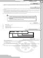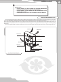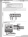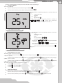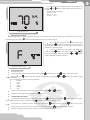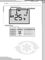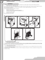
1
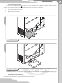
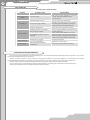
USER’S MANUAL
Micra 150 E
Air handling unit with heat recovery
Micra 150 E
2
CONTENT
Introduction
Use
Delivery set
Structural designation key
Technical data
Safety requirements
Structure and operating logic
Mounting and set-up
Connection to power mains
Unit control
Maintenance
Fault handling
Storage and transportation rules
Manufacturer’s warranty
Acceptance certificate
Seller information
Mounting certificate
Warranty card
3
3
3
3
3
4
5
6
8
8
14
16
16
17
18
18
18
19
3
INTRODUCTION
The present user manual consisting of technical details, operating instructions and technical specification covers the installation of
the MICRA 150 E air handling unit with heat recovery, VENTS series (hereinafter referred as the unit).
USE
The unit is designed to save thermal energy by means of heat recovery and is one of the energy saving components used in buildings
and premises.
The unit is designed to provide permanent controllable air exchange by mechanical ventilation in houses, offices, hotels, cafés,
meeting halls and other mechanically ventilated premises as well as utilization of extract air heat energy to warm up supply purified air.
The air handling unit is a component unit and is not designed for independent operation.
Transported medium must not contain any flammable or explosive mixtures, evaporation of chemicals, coarse dust, soot and oil
particles, sticky substances, fibrous materials, pathogens or any other harmful substances.
THE UNIT IS NOT DESIGNED TO BE USED BY CHILDREN, PHYSICALLY OR MENTALLY DISABLED
PERSONS, PERSONS WITH SENSORY DISORDER OR WITH NO APPROPRIATE EXPERIENCE OR EXPERTISE.
THE UNIT MUST BE HANDLED ONLY BY PROPERLY QUALIFIED PERSONNEL AFTER THE APPROPRIATE
SAFETY BRIEFING.
INSTALL THE UNIT TO BE OUT OF REACH OF CHILDREN.
DELIVERY SET
Unit - 1 item;
Remote controller - 1 item;
User manual - 1 item;
Master plate - 1 item;
Fasteners (dowel 8x80 and countersunk-headed screw) - 4 items;
Shipping box - 1 item.
STRUCTURAL DESIGNATION KEY
MICRA
150
E
posistor electric heater
Air capacity [m3/h]
Unit name
TECHNICAL DATA
The unit is designed for operation in an enclosed area at ambient temperatures from +1 °C to + 40 °C at relative humidity of up to 80%.
The unit must be grounded!
Hazardous parts access and water ingress protection standard:
Unit motors - IP 44;
Unit assembly connected to air ducts - IP 22.
The unit series designations, the main overall and connecting dimensions, outer view and technical data are given in fig. 1 and in
table 1.
The unit design is regularly being improved, so some models can slightly differ from those ones described in this manual.
Micra 150 E
4
87
255
125
580
122,5
500
122,5
200
260
Fig. 1. Unit overall and connecting dimensions
Table. 1. Technical parameters of the unit
Type
Micra 150 E
Unit voltage 50 Hz [V]
1 ~ 230
Max. fan power [W]
9
Electric heater power [W]
16
40
350
Electric heater current [A]
1,6
Total unit power [W]
390
Total unit current [A]
1,68
Max. air capacity [m /h]
60
105
150
Rotation speed [min-1]
450
780
2000
Sound pressure level, 3 m [dB(A)]
30
35
38
3
Transported air temperature [°C]
from -25 °C up to +50 °C
Casing material
polymer coated steel
Insulation
10 mm foam rubber
Heat recovery efficiency [%]
60 - 80
Heat exchanger type
Counterflow
Heat exchanger material
Polysterene
Supply
Filter
Extract
Connected duct diameter [mm]
Weight [kg]
G4
G4
Ø 125
20
SAFETY REQUIREMENTS
While operating and mounting the unit consider the requirements of the present operation manual as well as general requirements of
all applicable local and national building and electrical codes and standards.
The unit must be grounded!
Before connecting the unit to power mains make sure that the unit is free of any visible damages or any other foreign objects inside the
casing that can damage the impeller blades.
WARNING!
DISCONNECT THE UNIT FROM POWER SUPPLY PRIOR TO ANY MOUNTING,
SERVICING, CONNECTION OR REPAIR OPERATIONS WITH THE UNIT.
5
RESTRICTIONS!
• DO NOT OPERATE THE UNIT BEYOND THE SPECIFIED TEMPERATURE
RANGE OR IN AN AGGRESSIVE AND EXPLOSIVE MEDIUM!
• DO NOT CONNECT CLOTHES DRYERS OR SIMILAR EQUIPMENT TO THE
VENTILATION SYSTEM!
• DO NOT OPERATE THE UNIT IN THE AIR AND DUST MIXTURE MEDIUM!
STRUCTURE AND OPERATING LOGIC
The unit operating principle is as follows (fig. 2). Warm stale air from the premises extracted by the unit is purified in the extract filter,
then it passes through the heat exchanger and then is exhausted outside through the ducts by the exhaust fan.
Clean cold intake air supplied to the unit is purified in the supply filter. The air passes through the heat exchanger and then fed into
the premises by the supply fan. Thermal energy of warm extract air is transferred to clean intake fresh air from outside and warms it up.
The air flows are fully separated. Heat recovery minimizes thermal energy losses, energy demand and operating costs for heating during
winter time.
The unit is equipped with a posistor 350 W electric heater to enable supply air warming up. The heater has overheating protection.
Intake air
Exhaust air
SUPPLY FILTER
EXTRACT FAN
HEAT EXCHANGER
Extract air
DRAIN PAN
Supply air
POSISTOR ELECTRIC HEATER
SUPPLY FAN
EXTRACT FILTER
Fig. 2. Design and operating logic
Micra 150 E
6
MOUNTING AND SET-UP
Mount the unit to provide enough access for maintenance or repair operations.
The wall for mounting must have even surface. Any surface irregularities will lead to unit casing skew and may prevent the unit from
operating properly. The minimum distances from the unit to the mounting surfaces are shown in fig. 3.
min 300 mm
min 300 mm
Fig. 3. Minimum distance from the unit to the surfaces
The unit is designed for installation directly in the premise to be ventilated. Prior to starting mounting operations mark and bore holes
in the wall with the master plate, fig. 4.
Mounting sequence with the master plate, fig. 5:
1. Fix the master plate on the wall with a self-adhesive tape at required level.
2. Indicate two marks for two holes Ø130 mm for air ducts and four holes Ø 8 mm for the unit fasteners.
3. Take off the master plate and drill through holes for the air ducts and holes, 90 mm deep for the unit fasteners. Insert the dowels,
remove the perforated fillers for the air ducts from the master plate and re-install the master plate back using a self-adhesive tape.
4. Insert the air ducts into the respective openings in the master plate.
5. Fill the spaces between the air ducts and the wall with a mounting foam through the specially designed holes in the master plate.
Wait till a mounting foam hardens (solidification time depends on the foam mark), take off the master plate and remove the foam excess.
Cut off the protruding air duct parts to be flush with the wall surface.
6. Insert the unit spigots to the air ducts.
7. Open the access door in the unit and remove the heat exchanger.
8. Mount the unit to the wall with the countersunk head screws and 8x80 dowels (included into delivery set) into two Ø 8 mm holes.
9. Install the heat exchanger and close the access door.
10. Fix the outer ventilation box (not included into delivery set) or Ø 125 mm ventilation grille on the outer wall of the building.
85
497
420
255
Point for cable rounding
inside the unit
2 holes for Ø 125 mm air duct.
Fill the gaps between the wall and the air
ducts with a mounting foam.
Point for cable rounding
inside the unit
38,5
Drill 4 holes with Ø 8 tool for 90 mm deep
as per master plate.
Fig. 4 Master plate
Drill 4 holes with Ø 8 tool for 90 mm
deep as per master plate.
145
190
180
545
575
2 holes for Ø 125 mm air duct.
Fill the gaps between the wall and the air
ducts with a mounting foam.
7
1.
2.
3.
4.
5.
6.
7.
8.
9.
Fig. 5. Unit mounting with the master plate
TWO Ø 125 MM AIR DUCTS
FOUR DOWELS WITH A SCREW
UNIT
Fig. 6. Unit mounting
FOUR DOWELS WITH A SCREW
(INCLUDED INTO OUTER BOX DELIVERY SET)
OUTER BOX
Micra 150 E
8
CONNECTION TO POWER MAINS
DISCONNECT THE UNIT FROM THE POWER MAINS PRIOR TO ANY OPERATIONS.
THE UNIT MUST BE PLUGGED INTO A PROPERLY INSTALLED POWER SOCKET
WITH AN EARTHED TERMINAL.
THE RATED ELECTRICAL PARAMETERS OF THE UNIT ARE SHOWN ON THE
RATING PLATE.
ANY TAMPERING WITH THE INTERNAL CONNECTIONS IS PROHIBITED AND
WILL VOID THE WARRANTY.
The unit is designed for connection to 230 V / 50 Hz single-phase AC mains.
The unit is supplied with a power cable and a plug. The unit must be connected to power mains through a grounded power socket
compliant with IEC 60884-1. The power cable is pre-wired to the terminal block X1 by the manufacturer, fig. 7.
Connect the unit to power mains through the external automatic circuit breaker integrated into the fixed wiring system. Install the
circuit breaker to have a free quick access in case of need to turn the unit off promptly.
The circuit breaker trip current must be in compliance with the current consumption. The recommended circuit breaker rated current
is 2.5 A. While selecting the automatic circuit breaker consider the maximum wire temperature that depends on the wire type, insulation,
length and layout way (open wire mounting, channel type or wall-mounted).
UNIT
X1
XP3
L
N
1
2
L
PE
LA
4
5
3
N
6
PE
~ 230 V / 50 Hz
Fig. 7. Power cable connection to terminal block
UNIT CONTROL
Control panel
Remote control panel
Unit On/Off
Fan speed up
Heater off
Heater on
Fan speed down
Speed 2
Speed 1
Speed 3
On/Off timer
Scheduled operation On
Remote Controller
Fan speed control buttons
Unit operation mode buttons (see details below)
Unit on/off
Fig. 8. Control panel and remote controller
9
The unit is controlled from the control panel as well as from the remote controller, fig. 8.
1. Turning unit ON/OFF
To turn the unit ON/OFF:
from the control panel: press the button Turning unit ON/OFF
;
from the remote controller: press the button Turning unit ON/OFF
.
The display shows the following indications as the unit is turned off,
fig. 9:
Indoor temperature;
Weekday;
Time;
OFF indication
;
When air supply to the heating elements is activated, the
and
indicator glows. Synchronously,
countdown of the air supply to the heater time starts (min : s)
Fig. 9. Display of the turned off unit
The control panel shows the following indications as the unit is
turned on, fig. 10:
Indoor temperature;
Weekday;
Time;
Fan speed indicator
Timer status information;
•
The indicator
is turned on.
•
The indicator
timer is turned off.
;
is displayed as the timer
is displayed as the
Heater status. If the heater is turned on, the indicator
displayed.
is
Fig. 10. Display in turned ON
2. Unit ventilation mode control.
The unit fan speed can be set in several ways:
From the control panel: Press the
1 - speed 2 - speed 3);
button to increase the speed or press the
From the remote controller: Press the
speed 1 - speed 2 - speed 3);
button to increase the speed or press the
From the remote controller: Press the
button to select speed 1, press the
select speed 3 correspondingly.
The control panel display shows the current fan speed status:
Indicator
— «Speed 1» mode;
Indicator
— «Speed 2» mode;
Indicator
— «Speed 3» mode.
button to reduce the speed cyclically (i.e. speed
button to reduce the speed cyclically (i.e.
to select speed 2 or press the
3. Supply air warming up
The electric posistor heater warms up supply air during cold season. To turn the heater ON/OFF:
from the control panel: press and hold the button
from the remote controller: press the button
and then press the button
.
to turn the heater on, press the button
to turn the heater off.
button to
Micra 150 E
10
WARNING!
IF THE HEATER IS ON, THE UNIT CAN BE TURNED OFF ONLY AFTER 20
SECONDS AFTER TURN-OFF COMMAND TO ENSURE THE HEATER COOLING. IN
THIS CASE THE INDICATOR
IS DISPLAYED.
4. Timer.
The timer enables automatic switching of the fans to the maximum speed with automatic reset after a set period of time in the range from
20 to 60 minutes.
The timer can be activated / deactivated:
From the control panel: to activate the timer press and hold the
button and then press the button. A single press of the button
sets the timer to 20 minutes while each subsequent press increases the timer setting in 10 minute increments. The maximum timer value is
60 minutes. To deactivate the timer press and hold the
button for 3 seconds;
From the remote controller: to activate the timer for 20 minutes press the
by means of the button
or
button. To deactivate the timer switch the unit off
.
5. Heat Exchanger Freezing Protection.
If the exhaust air temperature downstream of the heat exchanger falls below +3 °C the supply fan shuts down. When the air temperature
rises above the +3 °С threshold, the unit reverts to rated operation.
6. Unit setup modes
RE-ADJUSTMENT OF THE UNIT SETTINGS RESULTS IN LOSS OF THE FACTORY
SETTINGS!
FAN SPEED AND TEMPERATURE SENSOR SETUP IS POSSIBLE ONLY FROM THE
CONTROL PANEL!
Fan Speed Setup Mode.
At the setup stage each of the speed settings (Speed 1, Speed 2 and Speed 3) can be attributed a specific supply and exhaust fan
performance. To enter the fan speed setup mode switch off the unit, then press and hold the
button for 3 seconds.
button on the control panel and hold
Upon entering the setup mode the panel display screen will show
the
and
indicators (Fig. 11).
Set the fan speed as necessary using the
and
buttons.
While the speed is being set the display screen will show the
currently selected speed
,
or
.
Fig. 11. Fan speed setup
To change the supply fan power press and hold the
button, then press the
button to increase the speed or press the
button to decrease it. Each press of the
and
buttons increases or reduces the supply fan power in 1 % increments. While the
button is pressed the display screen will indicate the current supply fan power (Fig. 12).
To change the exhaust fan power press the
button to decrease the power. Each press of the
the
button and while holding it use the
and
button to increase the power or the
buttons increases or reduces the exhaust fan power in 1 % increments. With
button pressed the display screen will indicate the current exhaust fan power.
To exit the fan speed setup mode and save the changes press and hold the
the fan speed.
button. The remote controller cannot be used to adjust
11
To revert to the factory settings enter the fan speed setup mode,
press the
and
buttons simultaneously and hold them for 3
seconds.
Factory Fan Speed Settings:
Speed 1 — 40 %
Speed 2 — 70 %
Speed 3 — 100 %
Fig. 12. Fan speed setup
7. Filter replacement signal
When the filters have reached the end of their service life (3,000 hours) the operating mode temperature normally shown on the control
panel display is replaced by the
indicator prompting filter replacement or cleaning (Fig. 13).
In case of filter replacement alert
switch off the unit
by pressing the
button and disconnect it from the power
mains. Replace the filters (see the sequence given in the "Technical
Maintenance" section, page 14).
Connect the unit to the power mains and switch it on
by means of the
button on the control panel or the
button on the remote control. Then press the
simultaneously to reset the motor meter.
and
buttons
Fig. 13. Filter replacement signal
8. Date and Time Setup.
Switch the unit off.
To enter the date and time setup mode press and hold the
, button, then press the
While holding the
button select the parameter for adjustment by using the
adjusted is blinking.
The date and time parameters are ordered as follows:
1. Minutes;
2. Hours;
3. Day;
4. Date;
5. Month;
6. Year.
Set the necessary parameter value on the control panel using the
To exit the date and time setup mode press the
9. and
buttons. The parameter being
buttons.
button.
Scheduled Operation Mode.
To activate the scheduled operation mode press and hold the
The scheduled operation mode is confirmed by the
panel.
and
button on the control panel.
button, and then press the
button on the control panel.
indicator glowing on the display screen.
To deactivate the scheduled operation mode press and hold the
button, and then press the
button on the control
The scheduled operation mode can be activated or deactivated using the
button on the remote controller.
The timer settings will always prevail over the scheduled operation parameters.
Micra 150 E
12
10. Scheduled Operation Setup.
Each weekday has four entries that determine the fan switching to the set fan speed, turning the heater on or off.
To access the scheduled operation settings switch off the unit using the
on the remote controller.
Press and hold the
button on the control panel, then press the
button on the control panel or the
button
button.
Weekday
Entry
number
Heater
status
Time
Heater OFF
Heater ON
Fan speed
Fig. 14. time-scheduled operation indicators
To select the scheduled operation setup mode parameters hold the
selection as necessary.
button and use the
and
buttons to make the
Use the
and
buttons to set the parameter values.
Scheduled operation setup mode parameters (Fig. 14):
•
Entry number — there are four entries for each day.
•
Weekday — day setting.
•
•
•
Heater status - setup of the heater status for the current entry.
Fan speed — fan speed setting for the current entry.
Time — time setting for the current entry.
- heater ON,
To copy the entries to the following day press and hold the
Sunday onto Monday is not possible.
- heater off.
button, then press
. Please note that copying entries from
To exit the scheduled operation setup mode press the
button on the control panel or the
button on the remote
control.
A programming example for setup of the time-scheduled operation is stated in the table 2. The time-scheduled operation mode is
adjusted for warm season by default. While adjusting the time-scheduled operation mode set the heater status
.
Table 2. Programming example
Entry number
Weekday
1
Start
time
Mo.
07:00
Tu.
2
Mode
Heater
status
Start
time
medium speed
Off
08:00
07:00
medium speed
Off
We.
07:00
medium speed
Th.
07:00
Fr.
3
Mode
Heater
status
Start
time
low speed
Off
17:00
08:00
low speed
Off
Off
08:00
low speed
medium speed
Off
08:00
07:00
medium speed
Off
Sa.
10:00
medium speed
Su.
10:00
medium speed
4
Mode
Heater
status
Start
time
Mode
Heater status
medium speed
Off
22:00
low speed
Off
17:00
medium speed
Off
22:00
low speed
Off
Off
17:00
medium speed
Off
22:00
low speed
Off
low speed
Off
17:00
medium speed
Off
22:00
low speed
Off
08:00
low speed
Off
17:00
medium speed
Off
22:00
low speed
Off
Off
12:00
medium speed
Off
17:00
medium speed
Off
23:00
low speed
Off
Off
12:00
2 скор.
Off
17:00
medium speed
Off
23:00
low speed
Off
13
11. Alarms.
In case of alarm the unit is turned off and the control panel display the alarm indicators, fig. 15. The possible alarms are listed in the table 3.
Temperature sensor alarm
Condensate drain pan is full
Freeze protection sensor
breakout
Fig. 15. Alarm indication
Table 3. Unit alarms
ALARM
Temperature sensor
alarm
INDICATION
FAULT HANDLING
Contact your Seller for servicing.
Duct temperature sensor
breakout
Contact your Seller to remove the freeze
protection temperature sensor.
Freeze protection sensor
breakout
Follow the drain pan servicing sequence,
"Maintenance section", page 14.
Micra 150 E
14
MAINTENANCE
The unit requires maintenance works 3-4 times per year. Maintenance includes regular cleaning and the following operations:
1. Filter maintenance (3-4 timed per year).
Dirty filters increase air resistance in the system and reduce supply air volume. The filters require cleaning as they get clogged, but at least
once in 3-4 months. Vacuum cleaning is allowed. Replace the filters as they get clogged following the second cleaning.
Contact your seller for new filters.
To remove the filters, follow the procedure in the fig. 16:
1. Open the unit access door.
2. Remove the supply air filter above the heat exchanger;
3. Remove the heat exchanger from the unit by pulling its band;
4. Press the clamp and remove it;
5. Remove the extract air filter.
Install the filter in the reverse order.
1.
2.
4.
3.
5.
Fig. 16. Filter maintenance
2. Heat exchanger inspection (once per year).
Some dust can get accumulated on the heat exchanger block even in case of regular maintenance of the filters. To maintain the high
heat exchange efficiency, regular cleaning is required. To clean the heat exchanger pull it out of the unit and flush it with warm soap or mild
detergent water solution. Re-install the dry heat exchanger to the unit.
3. Fan inspection (once per year).
Even in case of regular filter and heat exchanger maintenance, some dust and grease can get accumulated inside the fans and reduce
the fan performance and supply air flow.
Clean the fans with a soft cloth or brush. No water and abrasive detergent, sharp objects or solvents are allowed for cleaning to prevent
the impeller damage.
15
4. Condensate removal (as required).
The drain pipes may get filled with condensate during cold season. As the drain pan gets filled with condensate, the unit is turned on
and the control panel displays the indicator to remind about the need to remove the condensate.
To remove condensate:
1. Disconnect the unit from power mains.
2. Open the unit door.
3.
Lift the condensate level switch.
4. Keep the condensate level switch, pull and remove the condensate drain pan carefully (Fig. 17).
Fig. 17. Drain pan removing
5. Empty the drain pan, lift the condensate level switch and re-install it back (Fig. 18).
Fig. 18. Drain pan installation
5. Supply air flow control (twice per year).
Leaves and other pollutions can clog the supply air grille and reduce the unit performance and supply air volume. Check the supply grille
twice per year and clean it as required.
6. Ductworks inspection (once in 5 years).
Even if you follow all the listed maintenance guidelines, some dust can get accumulated inside the air ducts and reduce the unit
performance. Duct maintenance means their regular cleaning or replacements.
Micra 150 E
16
FAULT HANDLING
Possible faults and fault handling
Problem
The fans do not get
started
Cold supply air.
Low set air flow.
Noise, vibration
Water leakage.
Possible reasons
Fault handling
No power supply.
Make sure the power supply line is connected
correctly, otherwise troubleshoot the
connection error.
The extract filter is soiled.
Clean or replace the extract filter.
The heat exchanger is frozen.
Check the heat exchanger for icing. Shut the
unit off if required and turn it on after the
freezing danger is no longer imminent.
The heater malfunction.
Please contact your Seller for servicing.
The filters, the fans are soiled, the
heat exchanger is soiled.
Clean or replace the filters; clean the fans and
the heat exchanger.
Check opening of the diffusers and louvre
shutters, check the extract hood and supply
grille and clean it of required; make sure the
air ducts are not soiled and not damaged.
Clean the fan impeller.
Tighten the screws to stop.
The ventilation system is soiled or
damaged.
The impeller is clogged.
Loose screw tightening.
The condensate level switch
malfunction.
Please contact your Seller for servicing.
STORAGE AND TRANSPORTATION RULES
Store the unit in the manufacturer’s original packing box in a closed ventilated premise with temperature range from +10°C to +40°C
and relative humidity less than 80% (at +20°C).
Vapours or particles which can cause corrosion or damage the insulation or connection tightness are not allowed in the storage
environment.Use hoist machinery for handling and transportation to prevent possible mechanical damages of the unit.
Fulfil the requirements for transportation of the specified cargo type during cargo-handling operations.
Use any vehicle types for the unit transportation provided that it is protected against mechanical or weather damage.
Avoid any mechanical shocks and strokes during handling operations.
17
MANUFACTURER’S WARRANTY
The manufacturer hereby warrants normal operation of the unit over the period of 24 months from the retail sale date provided the
user's observance of the transportation, storage, installation and operation regulations.
Should any malfunctions occur during the unit operation through the manufacturer's fault during the warranty period the user is
entitled to elimination of faults by means of warranty repair performed by the manufacturer.
The warranty repair includes work specific to elimination of faults in the unit operation to ensure its intended use by the user within the
warranty period. The faults are eliminated by means of replacement or repair of the complete unit or the faulty part thereof.
The warranty repair does not include:
•
Routine maintenance;
•
Unit installation / dismantling;
•
Unit setup.
To benefit from warranty repair the user must provide the unit, the user's manual with stamped sale date and the payment document
certifying the purchase.
The unit model must comply with the one stated in the user's manual.
Contact your Seller for warranty service.
The manufacturer's warranty does not apply to the following cases:
•
User's failure to provide the unit with the entire delivery package as stated in the user's manual or with missing component parts
previously dismounted by the user;
•
Mismatch of the unit model and make with the respective details stated on the unit packing and in the user's manual;
•
User's failure to ensure timely technical maintenance of the unit;
•
External damage to the casing (excluding external modifications of the unit as required for its installation) and the internal
components of the unit;
•
Alteration of the unit design or engineering changes of the unit;
•
Replacement and use of the unit assemblies, parts and components not approved by the manufacturer;
•
Unit misuse;
•
User's violation of the unit installation regulations;
•
User's violation of the unit management regulations;
•
Unit connection to the power pains with a voltage different from the one stated in the user's manual;
•
Unit breakdown due to voltage surges in the power mains;
•
User's discretionary repair of the unit;
•
Unit repair performed by any persons without the manufacturer's authorization;
•
Expiry of the unit warranty period;
•
User's violation of the established regulations specific to the unit transportation;
•
User's violation of the unit storage regulations;
•
Wrongful acts against the unit committed by third persons;
•
Unit breakdown due to circumstances of insuperable force (fire, flood, earthquake, war, hostilities of any kind, or blockade);
•
Missing seals if provided by the user's manual;
•
Failure to provide the user's manual with the sale date stamp;
•
Missing payment document certifying the unit purchase.
FOLLOWING THE REGULATIONS STIPULATED HEREIN WILL ENSURE A LONG AND TROUBLEFREE OPERATION OF THE UNIT.
USERS' CLAIMS SHALL BE SUBJECT TO REVIEW ONLY UPON PRESENTATION OF THE
UNIT, THE PAYMENT DOCUMENT AND THE USER'S MANUAL WITH THE SALE DATE
STAMP.
Micra 150 E
18
ACCEPTANCE CERTIFICATE
Product Type
Air handling unit with heat recovery
Model
VENTS Micra 150 E
Serial Number
Manufacturing Date
is compliant with the technical specifications and is hereby declared ready for service.
Quality Inspector’s
Stamp
SELLER’S INFORMATION
Shop name
Address
Phone number
E-mail
Sales date
This is to certify delivery of the complete unit with the user’s manual. The warranty terms are
acknowledged and accepted..
Seller's seal
Customer’s signature
MOUNTING CERTIFICATE
Air handling unit with heat recovery VENTS Micra 150 E has been connected to power mains pursuant
to the requirements stated in the present user’s manual.
Company name
Address
Phone number
Installation technician's
full name
Installation date:
Signature:
This is to certify that the work specific to the unit installation has been performed in accordance with
all the applicable provisions of local and national construction, electrical and technical codes and
standards. The unit operates normally as intended by the manufacturer.
Signature:
Installation technician's
company seal
19
WARRANTY CARD
Product type
Model
Air handling unit with heat recovery
VENTS Micra 150 E
Serial number
Manufacturing date
Sales date
Warranty period
Sales company
Seller's seal
______________________________________________________________________________________________________
______________________________________________________________________________________________________
______________________________________________________________________________________________________
______________________________________________________________________________________________________
______________________________________________________________________________________________________
______________________________________________________________________________________________________
______________________________________________________________________________________________________
_________________________________________________________________________________________________
2013
V73-1EN-05