1
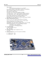
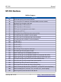
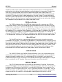
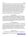
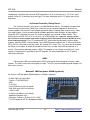
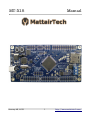
MTX1S Manual January 29, 2015 1 http://www.mattairtech.com/ MTX1S Manual Table of Contents Overview........................................................................................................................4 Introduction....................................................................................................................................... 4 MTX1S Features.............................................................................................................................. 4 ATxmega128a1 Features.................................................................................................................. 5 MTX1S Hardware.........................................................................................................7 Solder Jumpers................................................................................................................................. 7 Headers / Pin Descriptions................................................................................................................8 Buttons / Jumper............................................................................................................................. 10 Power / Status LEDs....................................................................................................................... 10 Power Supply.................................................................................................................................. 10 Clock Sources / RTC....................................................................................................................... 11 USB Serial Bridge........................................................................................................................... 12 MicroSD Card.................................................................................................................................. 12 32KB SPI SRAM............................................................................................................................. 12 RS232 / RS485............................................................................................................................. 12 Audio Amplifier................................................................................................................................ 13 1.25V Precision Reference.............................................................................................................. 13 Temperature Sensor....................................................................................................................... 13 8channel Lowside / Relay Driver....................................................................................................14 Windows Installation..................................................................................................15 Atmel Studio (AVR Studio) / AVRISP mkII driver.............................................................................15 WinAVR / AVRDUDE...................................................................................................................... 16 MTX1S Driver / Serial Configuration..............................................................................................17 Terminal Emulator........................................................................................................................... 17 Linux Installation........................................................................................................18 AVRISP mkII Compatible PDI Programmer..............................................................19 Using Atmel Studio (AVR Studio)....................................................................................................19 Using AVRDUDE............................................................................................................................ 23 Serial Bridge................................................................................................................24 Configuration..............................................................................................................26 XMEGA Demo Program..............................................................................................27 Firmware Updates.......................................................................................................28 Troubleshooting / FAQ...............................................................................................31 Support Information...................................................................................................31 Schematic....................................................................................................................32 Legal Notices...............................................................................................................33 Appendix A: Precautions...........................................................................................35 Appendix B: Other MattairTech Products................................................................36 January 29, 2015 2 http://www.mattairtech.com/ MTX1S January 29, 2015 Manual 3 http://www.mattairtech.com/ MTX1S Manual Overview Introduction The MTX1S is a flexible USB development board for the Atmel ATxmega128a1 microcontroller. Included is a MicroSD card slot, 32KB SPI SRAM, audio amplifier, lowside / relay driver, temperature sensor, RS232 or RS485, 4 LEDs, and an onboard 1.25V precision reference for the ADC. This reference is setup to work with the XMEGA errata. The XMEGA can be programmed over USB using the onboard AVRISP mkII compatible PDI programmer. The XMEGA can communicate with a computer using the onboard USB to serial bridge. Speeds up to 2Mbps are supported in synchronous mode (1Mbps in asynchronous mode). The Atmel AT90USB162 USB AVR, which provides these features, will automatically sleep when USB is disconnected. The board can be powered via USB or an external header. Voltage is regulated by a 3.3V, 1A LDO regulator. There are several clock options available onboard, including a 32.768KHz crystal, an external clock, an external HC49 crystal landing, and several internal clock options. Most XMEGA pins are routed to headers. The included peripheral devices are connected to the XMEGA via solder jumpers, which allows use of the pins if the device is not used. A demo program is preinstalled on the XMEGA demonstrating use of each peripheral device, as well as demonstrating sleep mode. Additionally, an Atmel Studio 6 ASF template is provided. All software used on both the XMEGA and USB AVR is opensource. MTX1S Features ● ● ● ● ● ● ● ● ● ● ● ● Atmel XMEGA 128A1U or 128A1(chip rev. H), 128KB flash, 8KB RAM Onboard USB PDI programmer (no external programmer needed) ● AVRISP mkII compatible ● Program flash, EEPROM, fuses, lock bits, and more ● Works with AVR Studio 4 and 5, Atmel Studio 6, AVRDUDE, Codevision, and BASCOM USB Serial Bridge ● Up to 2MHz baud rate (1MHz async) ● Synchronous or asynchronous operation ● Optional USB ready signal 3.3V, 1A LDO regulator Powered via USB or external header 32.768KHz crystal connected to TOSC (RTC) pins HC49 crystal landing connected to XTAL pins Most pins routed to headers (Port A through Port K) Solder jumpers can be used to disconnect devices when not used (frees up header pin) MicroSD card slot with pushpush spring action 32KB SPI SRAM chip 8 channel lowside / relay driver with kickback protection ● Up to 70mA per channel ● 5V or 3.3V devices (relays, LCD backlights, etc.) ● Can be used as general purpose lowside driver January 29, 2015 4 http://www.mattairtech.com/ MTX1S ● ● ● ● ● ● ● ● ● ● ● ● ● ● ● ● Manual Audio amplifier connected to XMEGA DAC Temperature sensor with lowpower operation 1.25V precision voltage reference ● Works with XMEGA ADC errata ● Use for signed differential conversions from 0V to ~2.5V at the pin ● Routed to both reference inputs via solder jumpers Choice of RS232 or RS485 serial interface, with powerdown and 3pin screw terminal 4 LEDs Available 1MB low power external SRAM (see http://www.mattairtech.com/) JTAG (XMEGA), PDI (XMEGA)*, and ISP (USB AVR) headers 4 boot modes selectable via jumper and button ● Serial bridge (default) ● AVRISP mkII compatible PDI programmer ● Configuration (uses terminal emulator) ● DFU bootloader (to update firmware on USB AVR via USB) Boot button can be used to toggle between the PDI programmer and the serial bridge Entire board can consume down to 75uA or less in sleep mode Atmel Studio 6 ASF (Atmel Software Framework) template to get started quickly Preloaded demo program demonstrates onboard peripheral devices as well as sleep mode PCB measures 10cm x 5cm Compatible with Windows XP/Vista/7/8 and Linux All firmware is opensource (MIT license) Uses LUFA USB library and AVRISP mkII clone by Dean Camera (http://www.fourwalledcubicle.com/) ATxmega128a1 Features Highperformance, Lowpower 8/16bit AVR® XMEGA Microcontroller NonVolatile Program and Data Memories 128K Bytes of InSystem SelfProgrammable Flash 8K Bytes Boot Section with Independent Lock Bits 2 KB EEPROM 8 KB Internal SRAM External Bus Interface for up to 16M bytes SRAM External Bus Interface for up to 128M bit SDRAM ● Peripheral Features Fourchannel DMA Controller with support for external requests Eightchannel Event System Eight 16bit Timer/Counters 4 Timer/Counters with 4 Output Compare or Input Capture 4 Timer/Counters with 2 Output Compare or Input Capture HighResolution Extension on all Timer/Counters Advanced Waveform Extension on two Timer/Counters ● ● January 29, 2015 5 http://www.mattairtech.com/ MTX1S ● ● ● ● Manual Eight USARTs IrDA modulation/demodulation for one USART Four 2Wire Interfaces w/ dual address match (I2C and SMBus) Four SPI (Serial Peripheral Interface) peripherals AES and DES Crypto Engine 16bit Real Time Counter with separate Oscillator Two Eightchannel, 12bit, 2 Msps Analog to Digital Converters Two Twochannel, 12bit, 1 Msps Digital to Analog Converters Four Analog Comparators with Window compare function External Interrupts on all General Purpose I/O pins Watchdog Timer with Separate Onchip Ultra Low Power Oscillator Special Microcontroller Features Poweron Reset and Programmable Brownout Detection Internal and External Clock Options with PLL and Prescaler Programmable Multilevel Interrupt Controller Sleep Modes: Idle, Powerdown, Standby, Powersave, Ext. Stby. Advanced Programming, Test and Debugging Interfaces JTAG (IEEE 1149.1 Compliant) PDI (Program and Debug Interface) I/O and Packages 78 Programmable I/O Lines 100 lead TQFP Operating Voltage (MTX1S operates at 3.3V) 1.6 3.6V Speed performance (MTX1S can operate at 032MHz) 0 12 MHz @ 1.6 3.6V 0 32 MHz @ 2.7 – 3.6V January 29, 2015 6 http://www.mattairtech.com/ MTX1S Manual MTX1S Hardware Solder Jumpers Jumper Description J1 USB Shield to gnd (not connected by default) J2 ~5V to relay driver (5V header pin and kickback diodes common cathode) J3 DACA0 (pin A2) to amplifier audio input J4 AREF B (pin B0) to 1.25V reference J5 AREF A (pin A0) to 1.25V reference J6 ADCA1 (pin A1) to temperature sensor output J7 Not present on MTX1S J8 SPI D SS (pin D4) to SRAM chip select (external pullup) J9 SPI D MOSI (pin D5) to SRAM SI (external pullup) J10 SPI D SCK (pin D7) to SRAM clock input (external pullup) J11 SPI D MISO (pin D6) to SRAM SO (external pulldown) J12 Pin D0 to LED_1 J13 Pin D1 to LED_2 J14 Pin D2 to LED_3 J15 Pin D3 to LED_4 J16 SPI F SCK (pin F7) to relay driver clock input J17 SPI F MOSI (pin F5) to relay driver SI input J18 USART F0 RXD (pin F2) to AT90USB162 USART TX J19 USART F0 TXD (pin F3) to AT90USB162 USART RX (shared with PDI_DATA) J20 USART F0 XCK (pin F1) to AT90USB162 USART XCK (also USB ready signal) J21 SPI E MISO (pin E6) to SD card SO (must enable XMEGA pullup) J22 SPI E SCK (pin E7) to SD card clock input (external pullup) J23 SPI E MOSI (pin E5) to SD card SI (external pullup) J24 SPI E SS (pin E4) to SD card chip select (external pullup) J25 Serial TX enable (pin E0) to RS232 _FORCEOFF_ or RS485 DE (external pulldown) J26 Serial RX enable (pin E1) to RS232 _EN_ or RS485 _RE_ (external pullup) J27 Serial RX (pin E2) to RS232 ROUT or RS485 RO January 29, 2015 7 http://www.mattairtech.com/ MTX1S Manual J28 Serial TX (pin E3) to RS232 DIN or RS485 DI (external pullup) J29 Serial Noninverting screwterminal to 680 ohm bias resistor to 3.3V (RS485 ONLY) J30 Serial Nonnverting screwterminal to 120 ohm termination resistor to Inverting screw terminal (RS485 ONLY) J31 Serial Inverting screwterminal to 680 ohm bias resistor to GND (RS485 ONLY) J32 3.3V to 33KOhm minimum current resistor to GND (MTX1S ONLY) Disconnect for lowest power consumption, but observe 3.3V regulator minimum load specification Headers / Pin Descriptions Pin Description External Power Header Under the default configuration, 5V should be supplied to this pin. Lower voltages may be used down to around 4V (or lower if using less current). Voltages greater than 5.5V require J2 to be disconnected. Disconnecting J2 will disable the 5V output pin and inductive kickback protection of the relay driver. But it will allow voltages up to ~7.5V. This header is reverse polarity protected using a schottky diode. 3.3V output headers (x4) There are four 2pin power output headers next to each port header group. The header next to the analog ports (ports A and B) comes from the analog 3.3V rail. Note that if these headers are installed, there will not be enough room to plug in IDC connectors next to each other. Relay Header 3.3V This can be used for the positive 3.3V side of a relay or other device. Relay Header 5V This can be used for the positive 5V side of a relay or other device. This is also the common cathode of the kickback diodes in the relay driver. Both of these are disabled when J2 is diconnected. Relay Header 18 These are the 8 relay driver outputs. They are opendrain active low. When enabled, the output is connected to ground. When disabled, the pin is in a high impedance state. When driving inductive loads, like relays, freewheeling diodes provide kickback protection (when J2 connected). Noninductive loads can also be connected (ie: LCD backlight). Each output is capable of sinking 70mA. Outputs can be combined. Audio Header This is the singe channel output from the audio amplifier. It can drive 8 ohm loads. 4 ohm loads may also be connected, but under some conditions, distortion or automatic thermal shutdown may occur. JTAG Header JTAG header for the XMEGA which can be used for programming, debugging, and JTAG boundary scans. Disable JTAG to gain access to the four underlying analog/GPIO pins. January 29, 2015 8 http://www.mattairtech.com/ MTX1S Manual PDI Header PDI header for the XMEGA which can be used for programming or debugging. Note that an onboard programmer is already provided. When using this header, J19 MUST be disconnected. This is due to the fact that RX and PDI_DATA are shared. This means that the XMEGA serial TX won't be connected to the USB AVR RX. This doesn't affect programming, but may present a problem in certain situations when debugging. If serial TX is required when debugging, the JTAG header can be used. Alternatively, an external USBserial bridge can be connected. ISP Header ISP header for the USB AVR which can be used for programming or debugging. The USB AVR can be programmed over USB using the DFU bootloader. Port A All pins are routed to headers. The 1.25V precision reference can be connected to pin A0 (Vref input) through a solder jumper. The temperature sensor output and audio amplifier input are also connected to this port. Port B All pins are routed to headers. The 1.25V precision reference can be connected to pin B0 (Vref input) through a solder jumper. Note that JTAG is connected to pins B4 – B7. JTAG must be disabled to use these pins for other purposes like the ADC. Port C All pins are routed to headers. No peripheral devices are connected to this port. Port D All pins are routed to headers. This port also connects to the LEDs and 32KB SPI SRAM memory through solder jumpers. Port E All pins are routed to headers. This port also connects to the buttons and the MicroSD card slot through solder jumpers. Port F All pins are routed to headers. This port also connects to the USART of the USB AVR (RX, TX, and optionally, XCK) as well as the SPI inputs of the relay driver (MOSI and SCK) through solder jumpers. To minimize power consumption. TX should be tristated before entering sleep. Ports H, J, and K All pins are routed to headers. No peripheral devices are connected to these ports. They can be used for GPIO or for use with external memory. Pins Q0 and Q1 The 32.768KHz crystal is connected to these pins, which serve as the TOSC input pins of the RTC. Pins Q2 and Q3 Pin Q2 is routed to the chip select pin of the relay driver. Pin Q3 is routed to the audio amplifier powerdown pin. Neither pin is routed to a header. Pins R0 and R1 Both of these pins are routed to an HC49 crystal footprint. A 22pF capacitor is also connected to each line. If an external clock is used, connect it to R1. Serial Screw Terminal Pin 1, which is closest to the port F header, is ground. This should always be connected, with both RS232 and RS485. Pin 2 is RX (RS232) or inverting (, RS485). Pin 3 is TX (RS232) or noninverting (+, RS485). January 29, 2015 9 http://www.mattairtech.com/ MTX1S Manual Buttons / Jumper There are four modes of operation which are selected using the PROG button and JMP jumper. The button and jumper are sampled when powering up or pressing reset. Additionally, the MT X1S can be switched between the AVRISP mkII programmer and the serial bridge during runtime by pressing the PROG button. This is useful, for example, to program the XMEGA, then switch to the serial bridge for printf() debugging. The reset button resets the USB AVR, which will in turn reset the XMEGA when it boots. The following table lists the mode selection during powerup and reset. Mode Selection During Powerup and Reset PROG Button JMP Jumper Mode Pressed Installed DFU Bootloader Not Pressed Installed Configuration Mode Pressed Not Installed AVRISP mkII PDI Programmer Not Pressed Not Installed USB Serial Bridge Power / Status LEDs There are two green LEDs that are used to indicate USB status, the mode of operation, communication activity, programmer status, and more. The following table lists LED functionality in each mode. Both LEDs are turned off in sleep mode. LED Functionality Mode STS LED PWR LED AVRISP mkII Programmer Programmer Activity PWM pulsing Configuration Mode On On USB Serial Bridge RX Activity TX Activity DFU Bootloader On Off Power Supply The MTX1S can be powered via USB or via an external header. Both sources are connected to the input of a 1A, 3.3V LDO linear regulator through Schottky diodes rated at 2A each (2A was chosen also to keep the dropout voltage low throughout the range of current). The diodes provide reversepolarity protection as well as ensuring that current will not flow from one source to the other. For example, if the external header has a greater voltage than the USB VBUS voltage, the diode January 29, 2015 10 http://www.mattairtech.com/ MTX1S Manual prevents VBUS from rising to the level of the external voltage. Note that there is a minimum load of 100uA for this regulator. The MTX1S can consume less than 75uA in the deepest sleep modes. An onboard load resistor between 3.3V and Gnd is provided to ensure that this requirement is met. A MicroSD card inserted may consume enough to meet the specification without the resistor, thus it can be disconnected by using solder jumper J32. The 3.3V regulator has thermal protection and foldback current limiting. There is a 10uF capacitor on both the input and output. Note that 10uF is the maximum allowed by the USB specification. When using the external header, additional capacitance may be needed with higher impedance voltage sources (ie: batteries, long cable runs). The regulator input can also be routed through J2 to the header pin labeled 5V (near the relay driver). Voltages greater than 5.5V on the external power input header require J2 to be disconnected, which will disable the relay driver kickback protection. Clock Sources / RTC By default, a 32.768KHz crystal is installed and connected to the TOSC pins of the XMEGA (R0 and R1). An HC49 crystal landing is available as well, with 22pF load capacitors preinstalled. An external clock can also be connected to pin R1. There are several internal clock options as well. The demo program makes use of the 32MHz internal RC oscillator. This oscillator is configured to be auto calibrated by a DFLL, which uses the 32.768KHz crystal as input. The crystal is also the source for the RTC. A 2MHz RC oscillator and two different 32KHz oscillators are also available. A PLL and prescalers can be used to obtain the various clocks. Be aware that the ATxmega128a1 requires both the 2MHz and 32MHz oscillators to be running and both DFLLs to be enabled for either DFLL to operate due to errata. Atmel ASF (Atmel Software Framework) does not support this arrangement, but the example code shows how to set this up. Also note that the DFLL calibrated oscillators will still not be as accurate as an external high speed crystal. If using an external crystal, it must be 0.4MHz to 16MHz. The PLL can be used to obtain higher clock speeds. Programming Headers The PDI header has the standard 6pin layout. Because an onboard programmer is provided, an external programmer is not necessary. However, debugging requires use of an external debugger connected to the PDI header or the JTAG header. Because the XMEGA TX pin (USB AVR RX/D pin) is connected to the XMEGA PDI_DATA pin, the debugger cannot be used when using TX as this would cause contention. However, solder jumper J19 can be disconnected to avoid contention, but TX will then be disconnected from the USB module. TX will still available on the header pin, so you can connect to an external serial bridge if debugging requires it. Alternatively, the JTAG header can be used for debugging. When using an external debugger or programmer on the PDI header, the USB AVR should be in any mode other than the PDI programmer. An ISP header is available for programming the USB AVR. It can also be programmed over USB (see Firmware Updates). Solder Jumpers / USB Shield There are many solder jumpers on the PCB connecting XMEGA pins to the onboard peripheral devices. This allows unused devices to be disconnected, freeing up the XMEGA pin, which is also January 29, 2015 11 http://www.mattairtech.com/ MTX1S Manual routed to a header, to be used for other purposes. External pull resistors are installed to keep the peripheral pins at a defined state during boot or when the peripheral is disconnected. They pull chip select lines to the deselected state to minimize power consumption. Most solder jumpers are connected by default. To disconnect for the first time, a small trace connecting the two jumper pads must be cut. To reconnect, create a solder bridge across the pads. Jumper J1 can be soldered to connect the USB shield to ground. The USB specification calls for the USB shield to be connected to ground on the host side only. However, it may be desired to ground this on the device side. An 0603 SMT component may be soldered on the solder jumper pads as well. USB Serial Bridge The USB Serial bridge allows the XMEGA to communicate with a computer over USB by simply using a USART. There is no need to learn the USB protocol or utilize a USB library. All USB functionality is handled by the USB AVR (AT90USB162). It simply relays bytes between the XMEGA and the host. The MTX1S uses two pins on USART F (RX and TX) in asynchronous mode and three pins (adding XCK) in synchronous mode. Optionally, a USB ready signal is available on the XCK pin. To minimize power consumption. TX should be tristated before entering sleep. This is due to the sharing of PDI_DATA and TX. PDI_DATA has a pulldown active, which will consume current when TX is set to output high. All three pins can be disconnected from the USB AVR using the solder jumpers. MicroSD Card The MicroSD card slot has a springloaded mechanism that locks the card in place when inserted (pushin, pushout). The contacts are goldplated. It is connected to SPI E using four pins. All pins have external 47Kohm pullups installed. All four pins can be disconnected from the MicroSD card slot using the solder jumpers. Note that when in the deepest sleep modes and a card is installed, it will likely consume the most current. Since the minimum load required by the regulator is 100uA, and the rest of the onboard components may consume less than 75uA, having a card installed may allow disconnection of the minimum load resistor (solder jumper), which itself consumes 100uA. 32KB SPI SRAM The 32KB SPI SRAM is the 23K256I/SN from Microchip. It has a very simple protocol, and can be quite fast operating at 16MHz with sequential access (ie: data capture). It is less suitable for storage that requires random access. It is connected to SPI D using four pins, all of which have 47Kohm external pull resistors. All four pins can be disconnected using the solder jumpers. A simple driver is provided in the ASF template. More more information, consult the datasheet. RS232 / RS485 The MTX1S comes with either an RS232 or RS485 interface IC installed. There are two different PCB footprints, but the screw terminals and I/O lines are shared. Therefore, only one can be installed on the PCB at a time. The RS232 IC is the MAX3221IPWR from Texas Instruments. The RS485 IC is the ISL3175EIUZ from Intersil. The IC is connected to USART E via four pins. They are RX, TX, RX enable, and TX enable. There are three 47Kohm pull resistors installed, a pullup on TX, and pull resistors on the enable lines that keep both disabled by default. All four pins can be January 29, 2015 12 http://www.mattairtech.com/ MTX1S Manual disconnected using the solder jumpers. The IC is connected to a 3pin screw terminal with 3.5mm pin spacing. The pin closest to header F is ground. The center pin is RX with RS232 installed, or Inverting () with RS485. The pin next to the MicroSD slot is TX with RS232 or NonInverting (+) with RS485. Note that the A/Y, B/Z naming is not used due to differing definitions among different manufacturers. When RS485 is installed, there is a 120ohm termination resistor installed between the inverting and noninverting pins, which can be disconnected using the solder jumper. Additionally, two 680 ohm resistors are installed that can be used to bias the inverting and noninverting pins to negative and positive voltages respectively. The IC does not require this biasing so the bias resistors are disconnected by default. When connecting wires to the screw terminal, take care not to short a wire to an LED as they are close in proximity. The location of the LEDs was chosen to minimize differences between the MTX1 and the MTX1S. When using RS232, be aware that the auto powerdown feature is enabled. This causes the TX driver to power down when the RX line is disconnected (no valid RS232 level present). One consequence of this is that a loopback test requires a pull resistor on RX to enable the TX driver, which will then keep RX at a valid level thereafter. For more information on either IC, consult the appropriate datasheet. Audio Amplifier The audio amplifier is the LM4889MM/NOPB from National Semiconductor. It is a single channel, class AB, 400mW @ 3.3V amplifier with depop and thermal protection. It is connected to the XMEGA DAC A0 on pin A2, which can be disconnected using a solder jumper. The shutdown pin is routed to pin Q3 and has a 47 Kohm pull resistor to keep the IC in shutdown when Q3 is not driven. The differential gain is set to 2, so the internal 1V reference or the external 1.25V reference can be used. An 8ohm or 16ohm speaker can be connected to the output which is routed to a two pin header. A 4ohm load can also be connected, but the amplifier may enter thermal shutdown if using a higher voltage reference and the signal magnitude remains large for a long enough period of time. For more information on this IC, please consult the datasheet. 1.25V Precision Reference The 1.25V precision reference is the ISL60002DIH312ZTK from Intersil. It is a lowpower FGA reference with a low 20ppm/C temperature coefficient. The initial accuracy is +/5mV. Because each MTX1S board is intended to be calibrated individually, the initial accuracy was deemed less important than the temperature coefficient. The reference is connected to both reference inputs, pins A0 and B0. It can be disconnected using the solder jumpers. The reference voltage of 1.25V was chosen as a workaround to the ADC errata of the ATxmega128a1. It is intended to be used with the ADC in differential mode and with signed conversions. The voltage to be measured is connected to the positive input, and the reference to the negative. This results in conversions in the ~0 to 2.5V range. See the source code for example setup and usage. For more information on this IC, please consult the datasheet. Temperature Sensor The temperature sensor is the MCP9701ATE/TT from Microchip. It is connected to pin A1, and can be disconnected by using a solder jumper. It can sense from 10C to 125C, though the high January 29, 2015 13 http://www.mattairtech.com/ MTX1S Manual temperature is limited to the maximum PCB temperature. It has an accuracy of +/ 2C (max.) and it outputs 19.5mV/C. It consumes only 6uA (typ.). For more information on this IC, please consult the datasheet. 8channel Lowside / Relay Driver The 8channel lowside / relay driver is the MAX4820 from Maxim. The outputs are opendrain. Each channel can drive low at 70mA each. Channels can be connected together to increase the current capability. All channels have kickback protection diodes, allowing them to driver relays. Note that solder jumper J2 must be connected for kickback protection to be available. All eight outputs, along with 3.3V (regulated Vcc) and ~5V (external voltage), are routed to a 10pin header. Thus, devices that use either 3.3V or 5V (ie: 5V relay, 5V LCD backlight) are supported. Voltages greater than 5.5V on the external power input header require J2 to be disconnected, which will disable the relay driver kickback protection. The IC is connected to SPI F and can be disconnected using the solder jumpers. Note that MISO is not connected, so the XMEGA cannot read from the IC. Also note that the SPI F SS line is not used as the chip select, but instead, Q2 is used. Thus, it is necessary to configure the SS pin as an output, or enable the pullup and leave it as an input so that SPI will operate as a master. The maximum operating speed is 2MHz. The protocol is very simple; essentially just a shift register. A simple driver is provided in the ASF template. For more information on this IC, please consult the datasheet. LEDs There are four LEDs connected to pins D0D3, and can be disconnected by using the solder jumpers. The LEDs are on when the outputs are high. The LEDs are connected to ground through 249 ohm series resistors. External 1MB lowpower SRAM (optional) An external 1 MB lowpower SRAM module is available separately. * 8Mbit (1024 x 8) static RAM * Cypress CY62158EV30 IC * 45ns * 2.2V3.6V * 18mA (25mA max) @ max speed * 2uA (8uA max) when not selected * 40C to +85C * 2 latches for address lines (20bit) * dedicated 8bit data lines * Measures 34.6mm x 25.0mm (1.36" x 0.98") * Fits EBI header on MTX1 development board January 29, 2015 14 http://www.mattairtech.com/ MTX1S Manual Windows Installation Before plugging in the MTX1S for the first time, the latest software and drivers must be downloaded. The MTX1S is supported under Windows XP, Vista (32 and 64 bit), and Windows 7 (32 and 64 bit). There is limited support for Windows 2000. The MTX1S appears as three different devices to the PC depending on which mode is selected by the button and jumper. These devices are the AVRISP mkII compatible programmer, the DFU bootloader for firmware updates of the USB AVR, and the USB CDC device (Virtual COM port) which is used for configuration mode and the USB Serial bridge. Therefore, three drivers are required. The AVRISP mkII and DFU drivers are included with software available on the Atmel website. The CDC driver is included with Windows, but requires an .inf file available on the MattairTech website. The following table lists the minimum versions of the required software. If the software provides a driver, is is listed as well. See the Firmware Updates section for installation of the DFU bootloader driver. Required Downloads Software AVR Studio / Atmel Studio Version Driver URL 4.19, 5.x, http://www.atmel.com/tools/AVRSTUDIO4.aspx OR AVRISP mkII http://www.atmel.com/tools/ATMELAVRSTUDIO.aspx or 6.x MTX1S Driver latest CDC driver https://www.mattairtech.com/software/MattairTech_CDC_D river_Signed.zip Atmel Studio (AVR Studio) / AVRISP mkII driver Atmel Studio (formerly AVR Studio) is a free IDE provided by Atmel that runs on Windows operating systems. It includes an assembler, debugger, simulator, and an AVR chip programming utility. As of June 2012, there are three main versions supported, the 4.x, 5.x, and 6.x series. The 4.x series is mature and stable, and can run on older hardware, however, it requires the use of the WinAVR gcc toolchain, which is out of date. It also lacks proper support for newer devices, like the XMEGA microcontrollers, but is a good option for older devices. AVR Studio 4.x is also smaller and less demanding on PC resources. If you choose to use the 4.x series, download version 4.19. You will also need to download and install WinAVR 20100110 prior to installation of AVR Studio. Both AVR Studio 5.x and Atmel Studio 6.x are supported by the MTX1S. They includes the compiler toolchain, as well as the AVR Software Framework (ASF). Use of the 5.x or 6.x series is recommended for the best support of the ATxmega128a1. Whichever version you choose, be sure to install the Jungo drivers when asked, which include the AVRISP mkII driver needed by the MTX1S AVR programmer. January 29, 2015 15 http://www.mattairtech.com/ MTX1S Manual Once Atmel Studio is installed, remove jumper JMP and plug in or reset the MTX1S while holding down the PROG button. This will run the AVRISP mkII compatible PDI programmer. LED_STS should be lit and LED_PWR should be PWM flashing on and off. You will then be prompted for the AVRISP mkII driver. By default, this is located in the Program Files/Atmel/AVR Jungo USB directory. Point the installer to the appropriate subdirectory for your PC architecture (usb32 or usb64) and install the driver. Do not use the driver in the AVR Tools/usb directory. Once the driver is loaded, the device will appear as the AVRISP mkII device under Jungo in the device manager. WinAVR / AVRDUDE WinAVR contains the GNU GCC compiler for C and C++, compiler tools, and libraries (including AVR Libc). It also includes AVRDUDE for Windows, which is a command line tool for transferring firmware to AVR microcontrollers. A graphical tool is included with AVR Studio. Download WinAVR from http://sourceforge.net/projects/winavr/files/WinAVR/20100110/ and install it first. To use AVRDUDE, you will need to download and install an update to libusbwin32 available at http://sourceforge.net/projects/libusbwin32/files/libusbwin32releases/. Choose the libusbwin32 develfilterx.x.x.x.exe file. Do this only after installing AVR Studio. You will also need to change the MTX1S AVRISP mkII Programmer host configuration to AVRDUDE. Note that WinAVR is outdated. It is not recommended for newer devices like the XMEGA series. AVRDUDE can also be installed separately. January 29, 2015 16 http://www.mattairtech.com/ MTX1S Manual MTX1S Driver / Serial Configuration Next, the MTX1S CDC driver can be installed, which is used by the serial bridge and configuration mode. This driver allows the board to appear as a COM port. The driver itself is included with Windows, but an .inf file is needed to configure it. Download the .inf file from https://www.mattairtech.com/software/MattairTech_CDC_Driver_Signed.zip. Note that Windows Vista 64bit, Windows 7 64bit and Windows 8 require the signed driver. Now, plug in or reset the MTX1S with jumper JMP removed. This will run the USBserial bridge. Both LEDs should be lit. Windows will then prompt you for the MTX1S CDC driver. Point the installer to the directory where you downloaded the driver and install. Note that you may need to rename the driver in order for it to show up in the installer. Windows may add the .txt extension to the file after downloading. Rename it so that it ends with .inf. Ignore any warnings given by the installer (ie: unsigned driver). Once the driver is loaded, the device will appear as the MTX1S CDC device using a COM port in the device manager. There is no need to configure serial port parameters. The buad rate, for example, is ignored. The MTX1S will always communicate with the computer at full speed (up to 2Mbps). If you experience any buffering problems, for example, a delayed response to user input, then change both buffer sizes to 1. Terminal Emulator Finally, the terminal emulator can be configured. Windows XP includes HyperTerminal, which has been tested with the MTX1S and will be documented here. There are several other terminal emulators available freely on the Internet. If you wish to use any of them, it should be no trouble to adapt the instructions presented here. Next, start HyperTerminal. Create a new connection. You will refer to this connection again, so give it an appropriate name (after it is configured, you can copy it to your desktop). Select the MTX1S COM port (ie: COM4) and continue. It is not necessary to configure the baud rate or any other serial parameters. Now, click on the connect icon. After connecting, you may see garbage on the terminal screen. If this is the case, click on the configuration icon and change the emulation to ANSI (or ANSIW). The configuration mode requires an ANSI terminal to allow drawing of the menu system. Normally, when first entering a mode that uses the CDC driver, a message that reads “Press any Key” is printed periodically. If you do not see this message, just press any key to continue. Note that it may not be possible to switch between modes using the button until a key is pressed. It is important to always click the disconnect icon before switching to the PDI programmer. Then click the connect icon a couple seconds after returning. This is required because changing to the AVRISP mkII driver unloads the CDC driver, then loads the AVRISP mkII driver. In order for the terminal to use the same COM port as before, it must be disconnected when returning to the CDC driver so that it does not assign a new COM port. January 29, 2015 17 http://www.mattairtech.com/ MTX1S Manual Linux Installation Linux is supported as well. You must download and build the toolchain from the latest script available at AVR Freaks on the AVR GCC Forum (Script for building AVR GCC sticky at http://www.avrfreaks.net/index.php?name=PNphpBB2&file=viewtopic&t=42631). All firmware written for the MTX1S is developed under Linux using this toolchain. Drivers TODO (drivers should already be installed) GCC Toolchain TODO (see opening paragraph) AVRDUDE TODO (ie: avrdude p x128a1 c avrisp2 P usb U flash:w:"myfirmware.hex") dfuprogrammer TODO (must use version 0.5.2 or higher) Terminal Emulator TODO (can use minicom, config port (ie: /dev/tty/ACM0), save config, run with minicom o) January 29, 2015 18 http://www.mattairtech.com/ MTX1S Manual AVRISP mkII Compatible PDI Programmer The MTX1S onboard PDI Programmer is based on the AVRISP mkII compatible programmer written by Dean Camera (http://www.fourwalledcubicle.com/). AVR Studio 4.19, 5.x, Atmel Studio 6.x, and AVRDUDE are supported. Using Atmel Studio (AVR Studio) Start Atmel Studio and open or create a new project. An example project, which can be used as a template, is available for the MTX1S at http://www.mattairtech.com/software/MTX1S/MT X1S_Simple_Demo.zip. To install, click File>Import>Project Template. Once installed, open the template by clicking File>New>Project and selecting the MTX1S_Simple_Demo. Once loaded, you can read the main source file. Also have a look at the src/config and src/asf/xmega/boards/mtx1 directories using the solution explorer pane. You may also wish to view the toolchain options with Project>Properties. January 29, 2015 19 http://www.mattairtech.com/ MTX1S Manual Next, build the project. Then, click on the Device Programming button. In the Device Programming window, select the AVRISP mkII as the tool. If no tool appears, be sure that the MTX1S is plugged in and in programming mode (STS LED will be pulsing). Select the ATxmega128A1 as the device and PDI as the interface and click Apply. You should now be connected to the AVRISP mkII compatible programmer with serial number 000200012345. Now click Read next to Device signature. It should match the device if all is well. It is recommended to always perform this step first to verify the connection. The target voltage will always read 3.3V. January 29, 2015 20 http://www.mattairtech.com/ MTX1S Manual Next, select the Memories page. In the Flash section, a hex file can programmed into the targets flash memory. Load your hex file, then click Program. The hex file for the MT X1S_Simple_Demo is located in the Debug folder. You will need to erase the target first if you do not have “Erase Flash before programming” checked. You should also verify the flash as well. January 29, 2015 21 http://www.mattairtech.com/ MTX1S Manual Next, select the Fuses page. It is best to leave the fuse settings alone until you understand what they do. In particular, do not set the BOD (Brownout detection) voltage too close to 3.3V, as this could cause the target to be held perpetually in reset. Due to errata, the BOD should not be enabled in sampled mode when active or idle (BODACT). Sampled mode is OK for other sleep modes (BODPD). Now you may wish to look at the other pages. Note that any firmware upgrade feature should not be used. The MTX1S PDI Programmer is not an actual AVRISP mkII, it just emulates one, so you should not attempt to update the MTX1S firmware using Atmel Studio. Any firmware updates will be posted to the website and loaded using FLIP or dfuprogrammer. January 29, 2015 22 http://www.mattairtech.com/ MTX1S Manual Using AVRDUDE TODO (ie: avrdude p x128a1 c avrisp2 P usb U flash:w:"myfirmware.hex") January 29, 2015 23 http://www.mattairtech.com/ MTX1S Manual Serial Bridge The serial bridge can connect the XMEGA to a host application (ie: terminal emulator) over USB. The XMEGA simply uses one USART as it would with, for example, RS232. There is no need to learn the USB protocol or use a USB library. On the host side, the MTX1S will appear as a virtual COM port. Speeds of up to 2Mbps are supported. Configuration Before using the serial bridge, it must be configured to be compatible with the target. This configuration is stored in EEPROM. There is no need to duplicate the settings on the host side, as communication between the host and MT X1S will always be the maximum supported USB speed, and the other parameters are ignored by the host. Only the connection between the USB AVR and the XMEGA use these settings. Note that when configuring the speed to be manual, it is possible to set the speed higher than 2MHz, but the maximum speed supported by the USB link is 2MHz. The serial bridge is configured in configuration mode (jumper on, button not pressed). Serial Bridge Configuration Options Configuration Option Possible Values Speed 2M, 1M, 500K, 250K, 125K, 76.8K, 57.6K, 38.4K, 19.2K, 9600, 2400, manual Baud Rate Register 0x0000 0x0FFF (if manual selected as speed) Clock 2X 1X, 2X Clock Mode async, sync Data Bits 5, 6, 7, 8, 9 When in synchronous mode, the USB AVR is the master, so the XCK pin is enabled as an output. The XMEGA must enable its clock pin as an input and be configured as a slave. When using 9bit data frames, two bytes are sent or received for every frame. The first byte simply contains the 9th bit, thus the first byte will always be 0 or 1. The second byte contains the rest of the 8 bits. January 29, 2015 24 http://www.mattairtech.com/ MTX1S Manual Baud Rate Register Value (Manual Speed) Async 1X f osc −1 16∗BAUD UBRR= f osc 16∗UBRR1 BAUD= UBRR= BAUD= Async 2X Synchronous f osc −1 8∗BAUD UBRR= f osc 8∗UBRR1 BAUD= f osc −1 2∗BAUD f osc 2∗UBRR1 where f osc =8000000 January 29, 2015 25 http://www.mattairtech.com/ MTX1S Manual Configuration The MTX1S PDI programmer, serial bridge, and other features can be configured by entering configuration mode. This configuration is stored in nonvolatile EEPROM memory. Configuration mode requires an ANSI terminal emulator. Configuration options are highlighted by using the up and down arrow keys, and selected using the enter key. Some dialogs are for entering numbers in hexadecimal. Here, the left and right arrow keys and backspace are used. The menu system is structured as follows: ● ● ● Serial Speed ● List of selectable speeds: 2400, 9600, 19.2K, 38.4K, 50.0K, 76.8K, 125K, 250K, 500K, 1M, 2M ● Manual (when selected, configure using Manual Settings below) Manual Settings ● Baud Rate Register ● Clock 2X ● (USB ready signal is opendrain active low on XCK pin from USB AVR) Disabled or Enabled AVRISPmkII ● (Which sleep mode is used when USB is disconnected or suspended) Power Down or Standby Ready Signal ● ● (async mode only) Asynchronous or synchronous Sleep Mode ● ● (enter value in hex) Serial Mode ● ● (Serial bridge speed selection) (select which software will be interfacing with the MTX1S PDI programmer) AVR Studio or AVRDUDE Credits (displays list of firmware authors) The USB AVR automatically enters sleep mode when the USB cable is disconnected or the USB bus is suspended. Sleep mode is by default set to Power Down, which provides for the lowest current consumption. The USB ready signal is useful when the XMEGA needs to know when the USB cable is disconnected or the USB bus suspended. The signal is opendrain activelow from the USB AVR XCK line, which may also be used for synchronous serial operation. The XMEGA must enable the pullup on this line before reading it. If it reads low, USB is enumerated and ready. Otherwise, it will read high. If synchronous operation in used, the XCK clock signal will override this. However, when USB is disconnected or suspended, the clock will stop and the the line driven low. When changing serial speeds, be sure to also change the speed in the XMEGA. January 29, 2015 26 http://www.mattairtech.com/ MTX1S Manual XMEGA Demo Program Note: This page describes the preinstalled demo program. This program is primarily meant for testing. While the source code is available, it is not intended to be reused. The code is a collection of many code fragments. It is disorganized and complicated. It is recommended to use the Atmel Studio 6 ASF (Atmel Software Framework) template to get started (see Using Atmel Studio (AVR Studio)). The following relates to the preinstalled demo. XMEGA uses serial bridge to display menu system on ANSI compatible terminal emulator screen. Remove the jumper and boot the board without pressing the button (remember that the terminal must be disconnected while resetting). Press any key, and the main demo menu will appear. Now, all interaction is with the XMEGA via the USB serial bridge. MicroSD Card Demo: The SD card demo makes use of the FatFS module from ChaN. FAT12, FAT16, and FAT32 are supported. Press 'h' for a help menu. Audio Demo: You can load wav files from the SD card and play them over an ~8 ohm speaker connected to the audio amplifier. You will need to use an audio program (like sox), to encode music or sound to 8bit or 16bit (recommended), 44.1KHz or less, mono uncompressed PCM. Then, in the audio demo, select the file chooser and pick a file. You can use the slider to adjust volume. When using the sleep demo, current measurements can be made using the external power header. Disconnect J2 to allow voltages above 5.5V. Supply 6.0V – 7.5V to this header so that current is drawn from this connector rather than from USB. Running the demo will put the XMEGA to sleep with the RTC running and waking the cpu every second to update the time. Most current consumption will then be from the USB AVR. Now unplug USB. The current consumption will drop further. Currently, ~75uA is consumed by the board in this state (without MicroSD card installed). Not all low power features are used, so this number can be lowered further. But note that a minimum load of 100uA should be present on the regulator output. The measured current at the external connector includes the regulator ground current, which will add to the 100uA minimum load. January 29, 2015 27 http://www.mattairtech.com/ MTX1S Manual Firmware Updates The MTX1S firmware will be updated periodically to add new features and fix bugs. These updates will be available on the MattairTech website. The updates may include just a hex file (for programming flash), or both a hex file and eep file (for programming both flash and EEPROM). FLIP is a graphical utility for Windows used to load firmware updates onto the MTX1S. FLIP includes the DFU bootloader driver. Download FLIP 3.4.2 or higher from http://www.atmel.com/tools/FLIP.aspx and install. If required to install a signed driver, then consult the table below for the download link. Downloads required for Firmware Updates Software Version Driver MTX1S Firmware latest (At90USB162) N/A FLIP 3.4.2 + Signed DFU Driver latest URL http://www.mattairtech.com/software/MTX1S/MT_X1S.hex DFU driver http://www.atmel.com/tools/FLIP.aspx http://www.avrfreaks.net/index.php?module=Freaks DFU driver %20Academy&func=viewItem&item_type=project&item_id=219 6 Once FLIP is installed, the DFU bootloader driver can be loaded. Plug in the MTX1S with jumper JMP installed and while holding down the PROG button. This will enter the DFU bootloader. LED_STS should be on and LED_PWR should be off. Windows will then prompt you for the AT90USB162 driver. By default, this is located in the Program Files/Atmel/Flip 3.4.2/usb directory. Once the driver is loaded, the device will appear as the AT90USB162 device under Atmel USB Devices in the device manager (note that ATmega32U2 is shown in screenshots). January 29, 2015 28 http://www.mattairtech.com/ MTX1S Manual FLIP Plug in the MTX1S with jumper JMP installed and while holding down the PROG button. This will enter the DFU bootloader. LED_STS should be on and LED_PWR should be off. Now launch the FLIP utility. When it has loaded, click on the chip icon and select the AT90USB162. Next, click on the USB icon, select USB, then connect. The screen should now show information about the AT90USB162. Click on the File menu, and open the appropriate hex file. More information will appear about the program. Be sure that erase is checked. The MTX1S firmware cannot be loaded unless the flash is erased first. Program must be checked. Verify should also be checked. Now click on the Run button in the lowerleft of the screen, and the firmware will be quickly loaded onto the MTX1S. If you encounter problems, you will need to unplug the MTX1S, disconnect FLIP, and start over making certain that the above settings are observed. January 29, 2015 29 http://www.mattairtech.com/ MTX1S Manual You may also need to program the EEPROM. If so, click on Select EEPROM at the bottom. Then, click on the File menu and open the appropriate eep file. You will have to change the file filter to allow you to see the eep file. Note that eep files are just hex files but with the eep extension instead of hex. More information will appear about the file when selected. Both Program and Verify should be checked. Click run to program the EEPROM. dfuprogrammer TODO Must erase chip first. Cannot read flash. dfuprogrammer at90usb162 erase dfuprogrammer at90usb162 flasheeprom MT_X1S.eep (if applicable) dfuprogrammer at90usb162 flash MT_X1S.hex January 29, 2015 30 http://www.mattairtech.com/ MTX1S Manual Troubleshooting / FAQ Nothing yet Support Information Please check the MattairTech website (http://www.MattairTech.com/) for firmware and software updates. Email me if you have any feature requests, suggestions, or if you have found a bug. If you need support, please contact me (email is best). You can also find support information at the MattairTech website. A support forum is planned. Support for AVRs in general can be found at AVRfreaks (http://www.avrfreaks.net/). There, I monitor the forums section as the user physicist. Justin Mattair MattairTech LLC PO Box 1079 Heppner, OR 97836 USA 541-626-1531 [email protected] http://www.mattairtech.com/ Acknowledgments Thanks to Dean Camera (http://www.fourwalledcubicle.com/) for his excellent LUFA library, AVRISP mkII clone, and DFU bootloader, all of which are used in the MTX1S firmware. Thanks to the members of AVRfreaks (http://www.avrfreaks.net/) for their support. Finally, thanks to Atmel for creating a great product, the AVR microcontroller. January 29, 2015 31 http://www.mattairtech.com/ MTX1S Manual Schematic January 29, 2015 32 http://www.mattairtech.com/ MTX1S Manual Legal Notices Copyright Notices Copyright Copyright Copyright Copyright Copyright © © © © © 2009-2012, Justin Mattair (http://www.mattairtech.com/) 2009-2012, Dean Camera (http://www.lufa-lib.org) 2003-2012, Atmel Corporation (http://www.atmel.com/) 2009, CHaN (http://elm-chan.org/fsw/ff/00index_e.html) 2010, Peter Kwan (serial demo) Software Disclaimer The author(s) disclaim all warranties with regard to this software, including all implied warranties of merchantability and fitness. In no event shall the author(s) be liable for any special, indirect or consequential damages or any damages whatsoever resulting from loss of use, data or profits, whether in an action of contract, negligence or other tortious action, arising out of or in connection with the use or performance of this software. Hardware Disclaimer This development tool is intended for use for FURTHER ENGINEERING OR DEVELOPMENT PURPOSES ONLY. It does not comply with some or any technical or legal requirements that are applicable to finished products, including, without limitation, directives regarding electromagnetic compatibility, recycling (WEEE), FCC, CE, or UL (except as may be otherwise noted). MattairTech LLC supplied this development product AS IS, without any warranties, with all faults, at the buyer's and further users' sole risk. The user assumes all responsibility and liability for proper and safe handling of the goods. Further, the user indemnifies MattairTech LLC from all claims arising from the handling or use of the goods. Due to the open construction of the product, it is the user's responsibility to take any and all appropriate precautions with regard to electrostatic discharge and any other technical or legal concerns. The product described in this document is subject to continuous development and improvements. All particulars of the product and its use contained in this document are given by MattairTech LLC in good faith. However all warranties implied or expressed including but not limited to implied warranties of merchantability or fitness for particular purpose are excluded. This document is intended only to assist the reader in the use of the product. MattairTech LLC shall not be liable for any loss or damage arising from the use of any information in this document or any error or omission in such information or any incorrect use of the product. Trademarks AVR® is a registered trademark of Atmel Corporation. All other trademarks are the property of their respective owners. January 29, 2015 33 http://www.mattairtech.com/ MTX1S Manual Licenses LUFA USB Library Copyright 2012 Dean Camera (dean [at] fourwalledcubicle [dot] com) Permission to use, copy, modify, distribute, and sell this software and its documentation for any purpose is hereby granted without fee, provided that the above copyright notice appear in all copies and that both that the copyright notice and this permission notice and warranty disclaimer appear in supporting documentation, and that the name of the author not be used in advertising or publicity pertaining to distribution of the software without specific, written prior permission. The author disclaim all warranties with regard to this software, including all implied warranties of merchantability and fitness. In no event shall the author be liable for any special, indirect or consequential damages or any damages whatsoever resulting from loss of use, data or profits, whether in an action of contract, negligence or other tortious action, arising out of or in connection with the use or performance of this software. January 29, 2015 34 http://www.mattairtech.com/ MTX1S Manual Appendix A: Precautions CAUTION The MT-X1S contains static sensitive components. Use the usual ESD procedures when handling. CAUTION Improper fuse settings may result in an unusable AVR. Be certain that you know the effects of changing the fuses, that you understand the convention used for describing the state of the fuses (programmed = 0), and that you are using an appropriate programming speed before attempting to change fuse settings. January 29, 2015 35 http://www.mattairtech.com/ MTX1S Manual Appendix B: Other MattairTech Products ZeptoProg II AVRISP mkII Programmer ● ● ● ● ● ● ● ● ● AVRISPmkII compatible AVR Programmer Supports all AVRs with ISP, PDI, or TPI Optional 5V output via headers to target board, with standard jumper and PTC fuse 4channel Logic Analyzer Serial bridge / pattern generator / SPI interface GPIO / PWM / frequency input & output Atmel Studio / AVRDUDE support Target board voltage of 2V to 5.5V via levelshifted pins on two main headers MTDBU6 USB AVR development board ● ● ● ● ● ● ● ● AT90USB646 / AT90USB1286 USB AVR 64KB/128KB FLASH, 4KB/8KB SRAM 5V, 500mA LDO regulator (3V30V input) Auto power source selection IC (USB/External) 16MHz and 32.768KHz crystals Arduino compatible CDC or DFU bootloader MTDBX4 USB AVR XMEGA board ● ● ● ● ● ● ● ● ATxmega128A4U USB XMEGA AVR 128KB FLASH, 8KB SRAM, 2KB EEPROM 3.3V LDO regulator (low quiescent current) 16MHz and 32.768KHz crystals LED, boot jumper, PDI header Reset button, mounting holes USB DFU bootloader preinstalled MTD21E USB ARM Cortex M0+ board ● ● ● ● ● ● ● ● January 29, 2015 ATSAMD21E17A or ATSAMD21E18A (32pin) 128KB/256KB FLASH, 16KB/32KB SRAM Onboard 3.3V, 250mA LDO regulator (2uA quiescent) 16MHz and 32.768KHz crystals USB connector (power by USB or external up to 15V) Blue LED, 10pin Cortex header, 2 buttons, I2C pullups USB Mass Storage Bootloader (no programmer required) 36 http://www.mattairtech.com/