1
IMPORTANT
,,
MANUAL
Do Not Throw Away
,,,
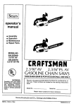
SEARS
Operator's
Manual
Model No.
358.351191
Always Wear Eye Protection
®
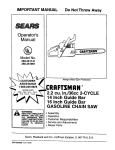
2.8 cu. in./46cc 2-CYCLE
1 inch Guide Bar
Turbo Air C :aner System
GASOLINE CH
SAW
d_b
READ THE OPERATOR'S
WARNING:
MANUAL AND FOLLOW
ALL WARNINGS
AND
SAFETY INS'I'RUCTIONS.
FA|LURETO DO SO CAN
RESULT IN SERIOUS
INJURY.
• Assembly
° Operation
° Customer Responsibilities
° Service and Adjustments
• Repair Parts
Sears, Roebuck and Co., Hoffman Estates, IL 60179 U.S.A.
530-083986-09/28/95
SAFETY
RULES
WARNING:
ALWAYS DISCONNECT SPARK PLUG WIRE AND PLACE WIRE WHERE IT CANNOT CONTACT
SPARK PLUG TO PREVENT ACCIDENTAL STARTING WHEN SETTING UP,TRANSPORTING,
ADJUSTING OR MAKING REPAIRS EXCEPT CARBURETOR ADJUSTMENTS.
BECAUSE A CHAIN SAW IS A HIGH-SPEED WOOD-CUTTING TOOL, SPECIAL SAFETY PRECAUTIONS MUST BE OBSERVED TO REDUCETHE RISK OF ACCIDENTS. CARELESS OR IMPROPER
USE OF THIS TOOL CAN CAUSE SERIOUS INJURY.
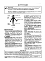
Hearing
,__
Safety Hat
Eye Protection
Snug
Fitting
Clothing
Heavy Duty Gloves
, Chaps
Safety
Shoes _,_
Figure t
KNOW YOUR SAW
- Read your operator's manual carefully until you
completely understand and can follow all safety rules,
precautions,
and operating instructions before
attempting to operate the uniL
• Restrict the use of your saw to adult users who
understand and can follow safety rules, precautions,
and operating instructionsfound in this manual.
- Do not handle or operate a chain saw when you
are fatigued, ill, or upset, or if you have taken alcohoi, drugs, or medication. You must be in good
physical condition and mentally alert. Chain saw work
is strenuous.. If you have any condition that might be
aggravated by strenuous work, check with your doctor
before operating a chain saw.
, Do not attempt to use your chain saw during bad
weather conditions such as strong wind, rain, snow,
ice, etc., or at night.
° Carefully plan your sawing operation in advance.
Do not start cutting until you have a clear work area,
secure footing, and, if you are felling trees, a planned
retreat path.
° Do not operate a chain saw that is damaged,
improperly adjusted,
or not completely
and
securely assembled. Always replace the handguard immediately if it becomes damaged, bro*
ken, or is otherwise removed.
, Keep the handles dry, clean, and free of oil or fuel
mixture.
o With the engine stopped, hand carry the chain
saw with the muffler away from your body, and the
guide bar and chain to the rear, preferably covered
with a scabbar&
FUEL HANDLING
° Eliminate all sources of sparks or flames in the
areas where fuel is mixed, poured, or stored. There
should be no smoking, open flames, or work that
could cause sparks. Allow engine to cool before refueling.
* Mix and pour fuel in an outdoor area on bare
ground; store fuel in a coot, dry, welt ventilated place;
and use an approved, marked container for all fuel
purposes.
, Wipe up all fuel spills before starting saw.
, Move at least 10 feet (3 meters) from the fueling
site before starting the engine.
• Do not smoke while handling fuel or while operating the saw.
, Turn the engine off and let your saw cool in a noncombustible area, not on dry leaves, straw, paper,
etc_ Slowly remove fuel cap and refuel unit.
° Store the unit and fuel in an area where fuel vapors
can not reach sparks or open flames from water
heaters, electric motors or switches, furnaces, etc
PLAN AHEAD
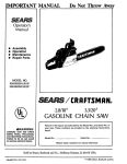
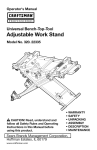
• Wear protective gear. Figure 1oAlways use steeltoed safety footwear with non-slip soles; snug4itting
clothing; heavy duty, non-slip gloves; eye protection
such as non-fogging, vented goggles or face screen;
an approved safety hard hat; and sound barriers - ear
plugs or mufflers to protect your hearing. Regular
users should have hearing checked regularly as chain
saw noise can damage hearing
= Keep all parts of your body away from the chain
when the engine is running.
, Keep children, bystanders, and animals a minimum
of 30 feet (10 Meters) sway from the work area. Do not
allow other people or animals to be near the chain saw
when starting or operating the chain saw
SAFETY NOTICE
1
Exposure to v brations through prolonged use of gasoline powered hand tools could cause blood vessel or nerve damage in the|
fingers, hand and joints of people prone to circulation disorders or abnormal swellings Prolonged use in cold weather has been|
linked to bood vesse damage in otherwise healthy people, if symptoms occur such as numbness, pain, loss of strength, change|
in skin color or texture or loss of fee ng n the | ngers, hands or joints, discontinue the use of this tool and seek medical atten-|
tion An anti-vibration system does not guarantee the avoidance of these problems. Users who operate power tools on a contin-|
ual and regular basis must monitor closely their physical condition and the condition of this unit
1
[_
IT
MEANS
AT'rENTION!!!
YOUR SAFETY
INVOLVED.
LOOK
FOR - THIS
SYMBOLTO BECOME
POINT ALERT!!!
OUT IMPORTANT
SAFETY IS PRECAUTIONS.
-2-
SAFETY
RULES
MAINTAIN YOUR SAW IN GOOD WORKING
ORDER
OPERATE YOUR SAW SAFELY
- Do not operate a chain saw with one hand, Serious
injuryto the operator, heipers, bystanders or any combination of these persons may result from one-handed operation. A chain saw is intended for two-handed
° Have all chain saw service performed by your Sears
Service Center with the exception of lhe items listed in
the maintenance section of thwsmanual_For example, if
improper tools are used to remove or hold the ltywheel
when servicing the dutch, structural damage to the flywheel can occur and cause the flywhee! to burst
° Make certain the chain stops moving when the throttle trigger is released. For correction, refer to
"Carburetor Adjustments,"
• Stop the saw if the chain strikes a foreign object.
Inspect unit and repair or replace parts as necessary,
• Disconnect the spark plug before performing any
maintenance except for carburetor adjustments.
° Never modify your saw in any way. Use only attachments supplied or specifically recommended by the manufacturer
• Use only quality SEARS accessories and replacement
parts as recommended for this unit
use,
• Operate the chain saw only in well-ventilated outdoor areas.
• Do not operate saw from a ladder or in a tree,
unless specifically trained to do so,
• Position all parts of your body to the left of cut and
away from the chain when the engine is running.
• Cut wood only. Do not use your saw to pry or shove
away limbs, roots, or other objects.
° Make sure the chain will not make contact with
any object while starting the engine. Never try to
start the saw when the guide bar is in a cut or kerr.
• Use extreme caution when cutting small size
brush and saplings. Slender material can catch the
chain and be whipped toward you or pull you off balance,
• Be alert for springback when cutting a limb that is
under tension so you will not be struck by the limb or
saw when the tension in the wood fibers is released.
° Do not put pressure on the saw at the end of a cut°
Applying pressure can cause you to lose control when
the cut is completed.
- Stop the engine before setting the saw down,,
- Keep fuel and oil caps, screws, and fasteners securely
tightened,
TRANSPORTING AND STORAGE
• Stop the unit before transporting
• Allow engine to cool, cover the guide bar and chain, and
secure theunit before storing or transporting in a vehicle
o Empty fuel tank before storing or transporting the unit
Use up any fuel left in the carburetor by starting the
engine and letting the engine run until it stops
° Store unit and fuel in an area where fuel vapors cannot
reach sparks or open flames from water heaters, electric
motors or switches, furnaces, etc
• Store unit so the chain cannot accidentally cause injury
• Store the unit out of the reach of children.
, i ,,
i , ii i,iiii1,,11111,,,11
,11
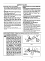
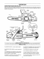
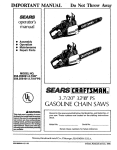
GUARD AGAINST KICKBACK - Kickback is a dangerous reaction that can lead to serious injury.
KICKBACK WARNING
Kickback
Path
KICKBACK
CAN OCCUR
THEATTHE
MOVING CHAIN CONTACTS
ANWHEN
OBJECT
UPPER PORTION OF THE TIP OF THE
GUIDE BAR OR WHEN THE WOOD CLOSES
IN AND PINCHES THE CHAIN IN THE CUT.
CONTACT AT THE UPPER PORTION OF
THE TIP OF THE GUIDE BAR CAN CAUSE
THE CHAIN TO DIG INTO THE OBJECT,
WHICH
STOPS THE CHAIN FOR AN
INSTANT. THE RESULT IS A LIGHTNING
FAST, REVERSE REACTION WHICH KICKS
THE GUIDE BAR UP AND BACK TOWARD
THE
OPERATOR.
IF THE
CHAIN IS
PINCHED ALONG THE TOP OF THE GUIDE
BAR, THE GUIDE BAR CAN BE DRIVEN
RAPIDLY BACK TOWARD THE OPERATOR.
EITHER
OF THESE
REACTIONS
CAN
CAUSE LOSS OF SAW CONTROL WHICH
CAN RESULT IN SERIOUS INJURY. DO NOT
RELY ONLY ON THE SAFETY DEVICES
PROVIDED WITH YOUR SAW. AS A CHAIN
SAW USER, YOU USER, YOU MUST TAKE
SPECIAL SAFETY PRECAUTIONSTO HELP
KEEP YOUR CUTTING JOBS FREE FROM
ACCIDENT OR INJURY.
Figure 2
Avoid
Obstructions
Clear The
Working Area
Figure 3
-3-
SAFETY RULES
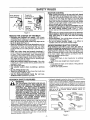
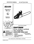
Never Reverse
Hand Positions
MAINTAIN CONTROL
• Keep a good, firm grip on the saw with both hands
when the engine is running and don't let go. Figure4
A firm grip can neutralize kickback and help you maintain
control of the saw Keep the fingers of your left hand
encirclingand your left thumb under the front handlebar
Keep your right hand completely around the rear handle
whether you are right handed or left handed Keep your
left arm straight with the elbow locked.
, Position your left hand on the front handlebar so it is
in a straight line with your right hand on the rear handle when making bucking cuts. Figure 4. Never
reverse right and left hand positionsfor any type of cutling
• Stand with your weight evenly balanced on both feet,
° Stand slightly to the left side of the saw to keep your
body from being in a direct line with the cutting
chain, Figure 4
• Do not overreach. You could be drawn or thrown off balance and lose controlof the saw
• Do not cut above shoulder height, It is difficult to
maintain controlof saw above shoulder height.
Thumb On
Under Side Of_
Handlebar
Elbow
I
Stand To
The Left
Of The Saw
t
!
Figure 4
REDUCE THE CHANCE
OF KICKBACK
understanding of kickback, you can reduce the etement
of surprise which contributesto accidents.
let the
movingchain
contact
any object
the
i Never
Recognize
that
kickback can
happen.
With a at
basic
tip of the guide bar.Figure 2
Keep the workingarea free from obstructions sucn as
other trees branches rocks fences, stumps, etc Figure
3 Eliminate or avoid any obstruction that your chain
could hit while you are cutting through a particular log or
branch
• Keep your chain sharp and properly tensioned. A
loose or dull chain can increase lhe chance of kickback
to occur Follow manufacturer's chain sharpening and
maintenance instructions Check tension at regular intervals with the engine stopped, never with the engine running. Make sure the bar clamp nuts are securety tightened after tensioning the chain.
• Begin and continue cutting at full throttle, If the chain
is moving at a slower speed, there is greater chance for
kickback to occur
o Cut one log at a time.
• Use extreme caution when re-entering a previous
cut,
UNDERSTANDING
REACTIVE FORCES
Pinch-Kickback and Putt-ln occur when the chain is
suddenly stopped by being pinched, caught, or by contacting a fore=gn object in the wood. This stopping of the
chain results in a reversal of the chain force usedto cut
wood and causesthe saw to move in the oppositedirection
of the chain rotation Either reaction can result in toss of
control and possibleserious injury.
• Pinch-Kickback
- occurs when chain on top of guide bar is suddenly
stopped
- rapidly drives saw straight back toward operator_
° Pull-In
- occurs when the chain on the bottom of the guide bar
is suddenly stopped
- pulls the saw rapidly forward
Watch for shifting logs or other forces that coutd close
I a ocut
not
and
attempt
pinch or
plunge
fall _ntochain_
cuts.
Use the Reduced-Kickback
Guide Bar and LowKickback Chain specified for your saw
i
i
KICKBACK
_
I I Ill"ll'l
SAFETY
I'm I'llllll'l
,;;;,,
FEATURES
THE FOLLOWING FEATURES ARE INCLUD*
WARNING
ED ON YOUR SAW TO HELP REDUCE THE
HAZARD OF KICKBACK; HOWEVER, SUCH
FEATURES WILL NOT TOTALLY ELIMINATE
THIS DANGEROUS REACTION. AS A CHAIN
SAW USER, DO NOT RELY ONLY ON SAFETY
DEVICES.YOU MUST FOLLOW ALL SAFETY
PRECAUTIONS, INSTRUCTIONS, AND MAINTENANCE IN THIS MANUAL TO HELP AVOID
KICKBACK AND OTHER FORCES WHICH
CAN RESULT IN SERIOUS INJURY.
Reduced-Kickback Guide Bar, designed with a smelt radius tip which
reduces the size of the kickback danger zone on the guide bar tip.
Figure 5 A Reduced-Kickback
Guide Bar is one which has been
demonstrated to significantly reduce the number and seriousness of
kickbacks when tested in accordance with ANSI B1751-1991
• Low-Kickback Chain, designed with a contoured depth gauge and guard
link which detlect kickback force and allow wood to gradually ride into
the cutter Figure 5 Low-Kickback Chain is chatn which has met
kickback performance requirements of ANSi B175 1-1991 when tested
on a representative sample of chain saws below 38 cubic inch displacement specilied in ANS_ B175 1-199I
-4-
• Handguard, designed to reduce the chance of your left hand contacting
the chain if you_"hand slips off the front handlebe_t
• Position of lront and rear handlebars, designed with distance between
handles and "in-line" with each other The spread and "in-line" position of
the hands provided by this design work together to give balance and
resistance in controlling the pivot of the saw back toward the operator if
kickback occurs.
* ANSi B175 1..1991 - Safety requirements for gasoline powered chain
saws as set by the American National Standards Institute, lnc,
Standard B175 1-1991
Contoured
Depth G_uge
_P""*""-_
Guard Ltnk
KickbaCk Force
e_uced
Kicld_¢k
Symm_tdc._l Guide ettt
Small
Rsdius Tip
Ch_iLow"P'lc_
gt_<
_
To Grac_ualfy Rid_
_ntoCu_e_
I_"_-_
Symmet_cal
Guide Br_r
L_ge
Radius 33p
"_"-.,.F"r
Ch_n W_thHig_
K_cld_8ckP_ent_el
Figure 5
Figure 5
Can Oi:_ltucl
_teriat
CONGRATULATIONS
on your purchaseof a Sears
Craftsman
GasolineChainSaw.It hasbeendesigned,
PRODUCT
engineered and manufactured to give you the best possible dependability and performance.
Should you experience any probiems you cannot easily
remedy, please contact your nearest Sears Service
Center/Department. Sears has competent, well trained
technicians and the proper tools to service or repair this
uniL
GUIDE BAR: .....................
CHAIN: ...............................
18" (46cm)
Low Proffie 325" Pitch
Chrome Cutters
DISPLACEMENT;
28 Cubic Inches (46cc)
..............
ENGINE: ...........................
2-cycle Air Cooled
FUEL MIX: ...................
40:t (32oz oil per galIon gas)
OILER: .......................................Automatic, 9,8 oz Tank
IGNITION: ......................
Solid State
Please read and retain this manual. The instructions witl
enable you to assemble and maintain your unit properly.
Nways observe the "SAFETY RULES."
MODEL NUMBER:
SPECIFICATIONS
(Air gap 010"-,0t4")
IGNITION TIMING: ................. Non-Adiustable, Fixed
SPARK PLUG TYPE: ............ Champion CJ-7Y
SPARK PLUG GAP: .............. 025" (65mm)
35&351191
MUFFLER: ........................
ENGINE RPM: ...................
DATE CODEtSERIAL NO,
Spark Arresting Screen
13,200 RPM Maximum
DATE OF PURCHASE:
THE MODEL AND SERIAL NUMBER WILL BE FOUND
ON THE PRODUCT
SPECIAL NOTICE
YoursaWis equipped with a temperature limiting muffler
and spark arresting screen which meets the requirements of California Codes 4442 and 4443. Al! U,S.forest
land and the states of California, Idaho, Maine, Minnesota,
New Jersey,Washington, and Oregon require many internal
combustion engines to be equipped with a spark arrestor
screen by law
YOU SHOULD RECORD BOTH SERIAL NUMBER AND
DATE OF PURCHASE AND KEEP IN A SAFE PLACE
FOR FUTURE REFERENCE.
MAINTENANCE AGREEMENT
If you operate a chain saw in a state or locale where such
regulations exist, you are legally responsible for maintaining the operating condition of these parts, Failure to
do so is a violation of the law, Refer to the Spark Arrestor
section under "Customer Responsibilities" for maintenance,
A Sears Maintenance Agreement is available on this product Contact your nearest Sears Stere for details
CUSTOMER RESPONSIBILITIES
= Read and observe the safety rules..
• Foltow a regular schedule in maintaining, caring for, and
using your unit.
• Fol!ow
the
instructions
under
"Customer
Responsibilities"
and "Storage" sections of this
Operator's Manual
MANUFACTURED
UNDER ONE OR MORE OF THE FOLLOWING
4 940.028 OTHER U S AND FOREIGN PATENTS PENDSNG
SPECIAL
U_
pATENTS:
NOTICE
If this saw is to be used for commercial logging, you must order and install a Chain Brake, to comply with
Federal OSHA Regulations for Commercial Logging. See Repair Parts List or call 1-800-235-5878,
FULL ONE YEAR WARRANTY
ON GAS CHAIN SAW
For one year from the date of purchase, when this Craftsman Gas-Powered Chain Saw is maintained, lubricated, and
tuned-up according to the owner's manual, Sears will repair, free of charge, any defect in material or workmanship.
This warranty excludes bar, chain, spark plug, and air filter, which are expendable parts and become worn during normal
Use
If this Gas Chain Saw is used for commercial or rental purposes, this warranty applies for only 30 days from the date of
purchase
WARRANTY SERV{CE IS AVAILABLE BY RETURNING THIS CHAIN SAW TO THE NEAREST SEARS SERVICE
CENTER IN THE UNITED STATES
This warranty gives you specific legal rights, and you may also have other rights which vary from state to state.
SEARS, ROEBUCK AND CO,, D/817WA, HOFFMAN ESTATES, IL 60179
-5-
=
=
i
=
,
i
n ,= i =,=,=r=,l,,,,,n,,r,,n,=
=
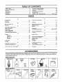
TABLE OF CONTENTS
'Ruies
i.,,_,,ii_ii_iiii
_ir, i,iiii*ii,iiiii_iiii,i
[/i_.,[.,iiii,,,,_ii_2
Customer ResponsiSiiitiesi,.,,,i,,ii_i_iioi,ii,.iill
.......................
lg
Product Specification ..................................................................................
5
Service and Adjustments
24
Warranty .....................................................................................
5
Storage ..................................................................................................
29
Accessories ................................................................................
6
Trouble Shooting Points
30
Assembly .........................................................................................
8
Repair Parts ....................................................................................
31
...................................................... 10
Repair Parts Ordering/Service ....................... Back Cover
safe_
..............................................................
.......................................
....................
,,11,1,1111i1,111,
i1,1
i, i
i
iiiii
i
i1,1
INDEX
i1,1
,,i,
i
i
,
,,i
,11,1,11111,,
r
i
,111,1,,,i,,,,,11,,i I
i
K
A
Accessories .............................................................................
6
Know Your Chain Saw .............................................................
10
L
Air Filter .................................................................................
22
Assembly
Lira bing ...............................................................................................
18
B
M
Bar and Chain Oif
12
Maintenance Schedule .........................................................
19
Model Number .............................................................................
5
Bucking
17
C
Muffler ...........................................................................................
22
O
Carburetor Adjustments ................................................................
27
Carton Contents ...............................................................................
7
Ope ration ............................................................................t0
Chain Oiler .................................................................................
11
Ordering Repair Parts ..............................................
Back Cover
P
Chain Sharpening ............................................................ 20
Product Specifications ......................................................... 5
Chain Adjustment ...................................................................
24
Customer Responsibilities ..................................................19
Pruning ...................................................................................
18
E
R
Engine
Repair Parts ....................................................................................
31
S
Fuel/Oil
12
Spark Plug
22
Service and Adjustments .............................................................
24
Starting
13
Spark Arrestor Screen ...................................................................
22
Storage ......................................................................................
29
Starter Rope ....................................................................................
25
F
Starting ........................................................................................
13
Fuel Filter
23
Storage
29
T
Fueling
12
G
Throttle Control Group ..........................................................
11
Guide Bar and Chain Oil .....................................................
12
Tree Felling ....................................................................................
15
Guide Bar Maintenance ........................................................
21
Trouble Shooting Points ................................................... 30
W
H
How To Use Your Chain Saw .....................................................
11
Warranty
..................................
..............................................
8
.................................................................
.....................................................................................
...............................................................................
....
....................................................................
.................................................................................
......................................
...............................................
......
..............................................
.....................................................................................
...........................................
.....................................................................................
,=1==
5
.....................
ACCESSORIES
These accessories and attachments were available when the unit was o';iglnatly purchas'ed They are also available at
most Sears retail outlets and service center& Most Sears stores can order these items for you when you provide the
model number of your unit.,
PERFORMANCE
Spark Plug
Air Filter
2-cycle
Gas Can
Bar Oil
Oil
_
Engine
3.2oz.
8 ozo
16ozo
1 qt,
1 gaL
MAINTAINENCE
Carrying
_
Gloves
Guide Bar
Safety
Goggles
-6-
Chain
Hearing
Protection
Chain
Sharpener
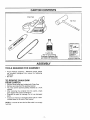
CARTON CONTENTS
ii
iii iiiiiiiiiiiii
Chain Saw
Fuel/Oil Mix
(Bar Oil not included)
Purchase Craftsman Bar
and Chain Oil Separately
Chain
Operator's Manual
ASSEMBLY
,
ilulllll,lll,
i,i
TOOLS REQUIRED
.................
i ii
,i,
FOR ASSEMBLY
• Torque Wrench (optional) - Reference torque values
are provided throughout this manual for tightening
hardware.
• Bar Toot
TO REMOVE CHAIN
FROM CARTON
SAW
• Remove loose parts bag included with Chain Saw
• Remove your saw from the packing material.
• You may use the opened packing material as a work
surface
= After removing the contents from the carton, check
parts against the Carton Contents list.
• Examine the parts for damage.. Do not use damaged
parts.
° If parts are missing or damaged please call the 1-800
number listed on the front of this manual
NOTE: it is normal to hear the fuel filter rattle in an empty
fuel tank
-7-
ii ,,11111
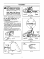
ASSEMBLY
_
ANGER:
DO NOT START THE ENGINE WITHOUT
THE GUIDE BAR AND CHAIN COMPLETELY ASSEMBLED.
OTHERWISE,
THE CLUTCH CAN COME OFF AND
SERIOUS INJURY CAN RESULT.
ALWAYS WEAR GLOVES WHEN HANDLING THE CHAIN.THE CHAIN CAN BE
SHARP ENOUGH TO CUT YOU EVEN
THOUGH IT ISTOO DULLTO CUTWOOD.
Clutch Drum
HOW TO ASSEMBLE YOUR CHAIN SAW
Guide Bar
Mounting Bolts
Guide Bar
Figure 8
BAR AND CHAIN ASSEMBLY (Fig.6-12)
•
•
=
•
•
•
•
,
•
Loosen and remove the 2 bar clamp nuts,
Remove bar clamp
Remove and throw away blue shipping spacer,
Turn adjusting screw by hand counterclockwise until
adjusting pin just touches the stop.
Mount guide bar with slotted end over both guide bar
mounting bolts, Slide guide bar behind clutch drum until
guide bar steps against the clutch drum sprocket, Install
the bar with "Craftsman" logo in up position(see Fig 8)
Carefully remove chain from bag Position chain with the
drive links as shown Fig_9,
Place chain over and behind the clutch drum Fig,10
Fit bottom of drive links between teeth in sprocket nose
Fit chain drive links into top of guide bar Fig, 9,
Gauge
Drive
Sprocket
Nose
CRRFTSMRN
Clutch Drum
Figure 6
Guide Bar
Mounting Bolts
Figure 9
Chain
Behind the
Clutch Drum
Adjusting
Screw
Adjusting
Pin
Figure 10
Stop
Figure 7
-8-
Guide Bar
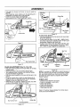
ASSEMBLY
o Pull guide bar forward until chain is snug in guide bar
qrooves
Adjusting
Screw
positioned in the lower hole in the guide bar
i Install
low, install
sure tight.
the adjusting pin is
two (2)bar
barclamp
clampmaking
nuts finger
Now proceed to the "Chain Adjustment" section
Guide Bar
1/4 Turn
Guide Bar
Bar Clamp
CRRFT_MRN.Bar Toot _
Bar Clamp
Nuts
jt
/
//
Lower Hole
Figure t4
To check chain tension:
• Use the screwdriver end of the bar tool to move chain
around the guide bar.
- If chain does not rotate, it is too tight - slightly loosen
bar clamp nuts and turn adjusting screw 1/4 turn counterclockwise. Retighten bar clamp nuts.
, tf chain is too loose, loosen bar clamp nuts; then, turn
adjusting screw 1/4 turn clockwise Lift up tip of guide
bar to check for sag Retighten bar clamp nuts..
Figure 11
Bar Tool
CRRFTSMRN°
Bar Clamp Nuts
Figure 12
CHAIN ADJUSTMENT
Bar Clamp
Nuts
Screw
Guide Bar
(Fig. 13, 14 & 15)
Roll chain around guide bar to ensure kinks do not exist,
(rotates freely)
Assure bar clamp nuts are loosened (finger tight).
Turn adjusting screw clockwise until chain just barely
touches the bottom of guide bar
• Roll chain around guide bar to ensure all links are in bar
groove,
• Lift up tip of guide bar to check for sag..Release tip of
guide bar, then turn adjusting screw 1/4 turn clockwise.
Repeat this step until sag does not exist.
• While lifting tip of guide bar, tighten bar clamp nuts with
the bar tool (provided)Torque 10-15 ft-lbs
Figure 15
NOTE: It is normal for a new chain to stretch. Because of
this initiat stretch during the first 15-30 minutes of operation, you should recheck your chain tension frequently
and adjust the chain tension as required (See "Chain
Tension" section).
CHECK LIST
• Check for loose fasteners and parts
Check for damaged or worn parts.
Check chain tension
• Check chain sharpness
• Guide Bar maintenance
° Check guide bar lube
Refer to "Customer Responsibilities" for further adjustments and recommendations
:RR
Bar Clamp Nuts
_'_G
uide Bar
Adjusting Screw
Figure 13
-9-
OPERATION
KNOW YOUR
CHAIN
SAW (Fig, 16)
READ THIS OPERATOR'S MANUAL AND SAFETY RULES BEFORE OPERATING YOUR CHAIN SAW. Compare the
illustrations with your unit to familiarize yourself with the location of the various controls and adjustments° Save this
manual for future reference,.
_HAND
GUARD
/
_.,_/HANDLE
/
CHAIN
ROPE HANDLE
_
A'
F1LLCAP
STARTER
L"_
r
" "-,\
FRONT
J
F
_
U|JlIIIIItlt
t
7._
_-
SWITCH
|
-
/
o
AND AIR FILTER
COVER
REAR
HANDLE
,
FUEL MIX
FILL CAP
STARTER
HOUSING
CYLINDER
/,_,_.,,,=
1
MUFFLER
THROTTLE
LOCKOUT
ADJUSTING
SCREW
CHAIN TRAVEL
DIRECTION
{:RRFTSMRN
o
CHOKE!
FAST,IDLE
CONTROL
THROTTLE
TRIGGER
BAR CLAMP
NUTS
GUIDE BAR
BAR CLAMP
I\1
in accordance
Figure 16
Listed by Underwriters Laboratories, Inc.
with American National Standards for Gasoline-Powered Chain Saws Safety Requirements
(ANSI B175.14991).
The ON/STOP SWITCH
The THROTTLE TRIGGER controls engine speed and
disengages the CHOKE/FAST IDLE control if set.
is used to stop the engine,
The STARTER ROPE HANDLE is used for starting the
engine.
The GUIDE BAR is designed to carry the chain.
The CUTTERS are designed to cut the wood.
The CHOKE/FAST IDLE CONTROL provides additional fuel to the engine when stating a cold engine, and
sets the throttle to "Fast Idle" position
The BAR CLAMP NUTS are designed to hofd the
guide bar after adjustments have been completed.
The THROTTLE LOCKOUT prevents the THROTTLE
TRIGGER from being squeezed accidentally
The ADJUSTING SCREW is designed to tension the
chain around the guide bar.
-10-
OPERATION
HOW TO USE YOUR CHAIN
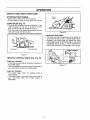
STOPPING
SAW
YOUR ENGINE
/A
Thrott{e
L_o_I
- Move on/stop switch to the "STOP" position,
- If engine does not stop, pull blue choke knob out fully
_
_=_
!/
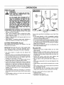
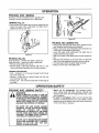
CHAIN OILER (Fig. 17)
• The chain oiler provides continuous lubrication to the
chain and guide bar Be sure to fill the bar oil tank
when you fill the fuel tank (Capacity=98 fL oz,)
• Your chain saw will consume approximately one tank
of bar oil for each tank of fuel used.
Your chain oiler is automatic and requires no adjustment
Trigger
Figure 18
CHOKE/FAST IDLE SPEED
• The choke and fast idle speed are set by pulling the
choke lever out fully for cold or refueled engine starts,
• Squeezing the throttle trigger will release the choke
and fast idle settings., If the throttle trigger is squeezed
accidentally during starting, it will be necessary to
reset throttle advance by pulling choke lever out fully°
Bat
capX
Front Handle
Fuel Mix Fiil Cap
__
Choke Pos_lons
I
Figure 17
THROTTLE
I
CONTROL GROUP (Fig. 18 & 19)
THROTTLE LOCKOUT
• The throttle lockout prevents unintentional actuation of
the throttle trigger.
• You must depress the throttle lockout with the palm of
your hand before actuating the throttle trigger.
Figure 19
THROTTLE TRIGGER
" The throttle trigger allows for variable control of
engine speed°
• The throttle trigger is actuated by the index finger on
your right hand (After the throttle lockout is
depressed),
-1!
U
'-'
Off
Full
o sto,
OPERATION
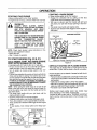
BEFORE
STARTING
ENGINE:
FUEL STABILIZER
Fuel stabilizer is an acceptable alternative in minimizing
the formation of fuel gum deposits during storage.. Add
stabilizer to gasoline in fuel tank or storage container
Always follow the fue! mix ratio found on the stabilizer
container. Run engine at least 5 minutes after adding
stabilizer to allow the stabilizer to reach the carburetor.
You do net have to drain the fuel tank for storage if you
are using fuel stabilizer_.
WARNING:
BE SURE TO READ THE FUEL HANDLING
INFORMATION IN THE SAFETY RULES
SECTION ON PAGE 2 OF THIS MANUAL
BEFORE YOU BEGIN.
IF YOU DO NOT UNDERSTAND THE FUEL
HANDLING SECTION DO NOT ATTEMPT
TO FUEL YOUR UNIT; SEEK HELP FROM
SOMEONE THAT DOES UNDERSTAND
THE FUEL HANDLING SECTION OR CALL
THE CUSTOMER ASSISTANCE HOTLINE
AT 1-800-235-5878.
CRAFTSMAN 40:1 2-cycle engine oil (AIR-COOLED) is
specially blended with fuel stabilizers° If you do not use
this Sears oil, you can add a fuel stabilizer to your fuel
tank.
40:1 2-CYCLE
GUIDE
AIR-COOLED
ENGINE OIL
CRAFTSMAN 40:1 2-cycle engine oil (AIR-COOLED) is
strongly recommended.This oil is specially blended with
fuel stabilizers for increased fuel stability (extends fuel
life up to 5 times longer) and reduced smoke
BAR AND CHAIN OIL
For maximum guide bar and chain life, we recommend
you use Craftsman chain saw bar oil If Craftsman bar oil
is not available, you may use a good grade SAE30 oil
until you are able to obtain Craftsman brand.The oil outpul is automatically metered during operation.. Your saw
will use approximately one tank of bar oil for every tank
of fuel mix.. Always fill the bar oil tank when you fill
the fuel tank.
If CRAFTSMAN 40:1 2*cycle engine oil (AIR-COOLED)
is not available, use a good quality 2-cycle engine oil
(AIR-COOLED) that has a recommended fuel mix ratio
of 40:1.
IMPORTANT! Do not use:
- AUTOMOTIVE OIL
• BOAT OILS (NMMA, BIA, etc.)
GASOLINE
The two-cycle engine on this product requires a fuel
mixture of regular unleaded gasoline and a high quality
40:1 2-cycle engine oii (AIR-COOLED) for lubrication of
the bearings and other moving parts. The correct fuelioii
mixture is 40:1 (see Fuel Mixture Chart). Too little oil or
the incorrect oil type will cause poor performance and
may cause the engine to overheat and seize.
These oils do not have proper additives for 2-cycle (AIRCOOLED) engines and can cause engine damage
GASOLINE
AND OIL MIXTURE
Mix gasoline and oil as follows:
- Consult chart for correct quantities.
• Do not mix gasotine and oil directly in the unit's fuel
tank
Gasoline and oil must be premixed in a clean approved
fuel container Always use fresh regular unleaded gaso*
line.
FOR ONE GALLON:
= Pour 3.2 ounces of high quality, 40:1 2-cycle engine
oil (AIR-COOLED) into an empty, approved one gatton
gasoline container.
• Add one gallon of regular unleaded gasoline to the
gallon container, then securely replace the cap.
, Shake the container momentarily.
° The mixture is now ready for use. Fuel stabilizer can
be added at this time if desired; follow mixing instructions on the label.
This engine is certified to operate on unleaded gasoline.
IMPORTANT:Experience indicates that alcohol blended
fuels called gasohol (or using ethanol or methanol) can
attract moisture, which leads to oii/gas separation and
formation of acids during storage., Acidic gas can damage the fuel system of an engine while in storage To
avoid engine problems, the fuel system should be emptied before storage for 30 days or longer Drain the gas
tank, then run the fuel out of the carburetor and fuel
lines by starting the engine and letting it run until it
stops. Use fresh fuel next season.. See STORAGE
instructions for additional information Never use engine
or carburetor cleaner products in the fuel tank or permanent damage may occur
FUEL MIXTURE
CHART
40:1 Fuel:O!! Mix Ratio
Gasoline
1 galton
2..°5gallons
3-2
8.0
NOTE: Fuel containers may hold more than the specified amount.. If too much gasoline is in the container,
the resulting gas-to-oil fuel mixture will not be correct
for proper engine operation.
-12-
OPERATION
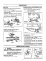
STARTING A WARM ENGINE
STOPPING
YOUR ENGINE
o Move on/stop switch to the "Stop" position
. If engine does not stop, pull blue choke knob out fully
ALWAYS WEAR
WARNING
GLOVES,
SAFETY
FOOTWEAR, SNUG-FITTING CLOTHING,
AND EYE, HEARING,
AND
HEAD
PROTECTION DEVICES WHEN OPERAT_
tNG A CHAIN SAW.
THE CHAIN MUST NOT MOVE WHEN THE
ENGINE RUNS AT IDLE SPEED. REFER
TO THE "CARBURETOR
ADJUSTMENTS" SECTION FOR CORRECTION.
• Move on/stop switch to the "On" position
• Engage the choke/fast Idle by pulling out the blue
choke knob fully and pushing it back in fully
• With saw on ground, grip front handle with left hand
and place your right foot through opening in rear handle° Pull starter rope handle until engine starts_
• Squeeze and release throttle trigger to return engine to
idle speed,,
STAR'rING POSITION
Right Hand
on
Starter Rope Handle
Left Hand
on
Front Handle
AVOID ANY CONTACT WITH THE MUFFLER. A HOT MUFFLER CAN CAUSE
SERIOUS BURNS.
NOTE: Check chain tension using instructions in the
"Service and Adjustment' section,
• Before first use.
= After 1 minute of operation,
TO START ENGINE
(Fig. 20 & 21)
Right Foot Through Opening In Rear Handle
COLD ENGINE START AND WARM ENGINE
START AFTER RUNNING OUT OF FUEL
° Fuel engine with 40:1 fuel mix (3.2 oz.to 1 gaL gas).
o Fill bar oil tank with bar oil, Your saw will use approximately one tank of bar oil for each tank of lueI mix
,, Turn on ignitionby moving on/stop switch to the "On"
position,
• Pull the blue choke/fast idlecontrol out fully to set both the
choke and fast idle for starting,Then set the saw on the
ground, Grip the front handle with your left hand and place
your right foot through the opening in the rear handle.
• IFTHROTTLETRIGGER IS SQUEEZED ACCIDENTALLY
DURING STARTINGITWILL BE NECESSARYTO RESET
I_HE CHOKE/FASTIDLE CONTROL.
NOTE - When pulling the starter rope, do not use the fu]f
extent of the rope as lhis can cause the rope to break. Do
not let the starter snap back, hold the handle and let the
rope rewind slowiy
• Pull starter rope handle with your right hand until the
engine attempts to start.
• Push the choke knob in to the "Off" position,
,, Continue to pull starter rope handle until engine starts.
• Then, allow engine to run for approximately 5 seconds.
° Then, squeeze and release throttle trigger to allow engine
to idle.
• To stop engine, move on/stop switch to the "Stop" position,
iS-.
tl
_,_
Figure 21
DIFFICULT STARTING OR FLOODED ENGINE
The engine may be flooded with too much fuel if it has not
started after 10 pulls,with the choke in the full out position
Flooded engines can be cleared of excess fuel withthe following procedure:
• Pull out the blue choke/fast idlecontrol fully and then push
it back intothe off position to set the fast idle control to the
start position.
= Verify that the on/stop switch is in the "On" position.
. With saw on ground, grip front handle with left hand and
place your right foot throughopening in rear handte_
• Pull starter rope handle until engine starts_
Starting could require pulling starter rope handle many
times depending on how badly unit is flooded.
If engine still fails to start, refer to "TROUBLE SHOOTING"
chart or call the 1-800 number listed on the front page of this
manual,
....\;
"_._
t
I
Figure 20
On/Stop
Choke Positions
- 13 -
OPERATION
GENERAL OPERATION TIPS
. Cut wood only, Do not cut metal; plastics; masonry; nonwood building materials; etc.
• Stop the saw ff the chain strikes a foreignobject, Inspect
the saw and repair or replace parts as necessary
. Keep the chain out of dirt and sand Even a small amount
of dirt will quickly dull a chain and thus increase the possibility of kickback.
To get the "feet" of using your saw before you begin a major
sawing operation, practice cutting a few small logs using the
following technique:
o Accelerate engine to full throttleby squeezing the throttle
trigger before entering cut.
o Never cut with engine at partial speeds.
• Begin cutting with the saw chassis against the log,,
• Keep engine at full throWeduring cutting procedure,
- Allow the chain to cut for you; exert only light downward
pressure,tf you force the cut, damage to the bar, chain, or
engine can result.
• Release the throttle triggeras soon as the cut is completed, allowing the engine to idle If you run the unit at full
throttle without cutting, unnecessary wear can occur to
the chain, bar, and engine
• To avoid losingcontrol when completing the cut, do not
put pressure on the saw during the end of Ihe cut.
. Stop engine before setting unit down after operation,
O PERATION SAFETY
WARNING
AVOID REACTIVE PINCH FORCES
tF SAW BECOMES PINCHED OR HUNG
tN A LOG, DO NOT TRY TO FORCE IT
OUT, YOU CAN LOSE CONTROL OFTHE
SAW RESULTING IN INJURY AND/OR
DAMAGE TO THE SAW° STOP THE SAW,
DRIVE A WEDGE OF PLASTIC OR
WOOD INTO THE CUT UNTIL THE SAW
CAN BE REMOVED EASILY. RESTART
THE SAW AND CAREFULLY REENTER
THE CUT. '1"O AVOID KICKBACK AND
CHAIN DAMAGE, DO NOT USE A METAL.
WEDGE,
DO
NOT
ATTEMPT
TO
RESTART YOUR SAW WHEN IT IS
PINCHED OR HUNG IN A LOG.
Pinch-Kickback and Pull-in occur when the chain is suddenly stopped by being pinched, caught, or by contacting a foreign object in the wood This sudden stopping of the chain
results in a reversal of the chain force used to cut wood and
causes the saw to move in the opposite direction of the
chain rotation. Pinch-Kickback drives the saw straight back
toward the operator,PuIl-ln pulls the saw away from the
operator Either reaction can result in loss of control and
possiblyserious injury
TO AVOID PINCH-KICKBACK:
° Be extremely aware of situations or obstructions that can
cause material to pinch the top of or otherwise stop the
chain
• Do not cut more than one log at a time
° Do not twist the saw as the bar is withdrawn from an
under-cut when bucking
KICKBACK CAN OCCUR WHEN THE
MOVING CHAIN CONTACTS AN OBJECT
ATTHE UPPER PORTION OFTHETIP OF
THE GUIDE BAR OR WHEN THE WOOD
CLOSES IN AND PINCHES THE SAW
CHAIN IN THE CUT_ CONTACT AT THE
UPPER PORTION OF THE TIP OF THE
GUIDE BAR CAN CAUSE THE CHAIN TO
DIG INTO THE OBJECT AND STOP THE
CHAIN FOR AN INSTANT° THE RESULT
IS A LIGHTNING FAST, REVERSE REACTION WHICH KICKS THE GUIDE BAR UP
AND BACK TOWARD THE OPERATOR. IF
THE SAW CHAIN IS PINCHED ALONG
THE TOP OF THE GUIDE BAR, THE
GUIDE BAR CAN BE DRIVEN RAPIDLY
BACK
TOWARD
THE
OPERATOR°
EITHER OF THESE REACTIONS CAN
CAUSE
LOSS OF SAW CONTROL
WHICH
CAN RESULT IN SERIOUS
INJURY,
TO AVOID PULL-IN
• Always begin cutting withthe engine at full throttleand the
saw housing against wood,
• Use wedges made of plastic or wood, (never of metal) to
hold the cut open_
-14-
OPERATION
TREE
FELLING
_
IF THE
TRUNK OR LIMBS ARE ROTTING,
ARNING
THEY CAN FALL UNEXPECTEDLY AND
CAUSE SERIOUS INJURY.,
AS YOU MAKE YOUR FELLING CUT, IF
THE SAW APPEARSTO BE BINDING,THE
TREE IS STARTING TO FAI_L IN THE
WRONG DIRECTION. IMMEDIATELY STOP
THE SAW AND USE A FELLING WEDGE
AND MAUL (HAMMER) TO FORCE THE
FELLING CUT OPEN. THE WEDGE WILL
HOLD THE FELLING CUT OPEN ALLOWING YOU TO REMOVE THE SAW. KEEP
EVERYONE AWAY FROM THE TREE IN
ALL DIRECTIONS.
DETERMINE
THE NATURAL
Bottom
Notch
Cut
PROCEDURE
After determining the Natural
should be cut as follows:
Buttress
Root
FALL DIRECTION
• Wind - A tree evenly balanced wilt fall in the same
direction the wind is blowing,
• Lean - Use a carpenter's level or plumb bob to determine if tree has a natural lean, A leaning tree wilt tend
to fall in direction of lean.
- Shape - A tree will tend to fall towards side that is more
heavily branched
- Other Factors - Contacting nearby trees, buildings, or
wires can influence the direction the tree will fall
CUTTING
I
I
I
Figure 22
tf your chain saw binds in the felling cut, you have three
options:
• If the wrong direction of fall is acceptable, carefully
remove the felling wedge, Cut deeper in the notch side
of the tree until tree starts to fall,
• If the wrong direction of fall is not acceptable, attempt
to use one or more felling wedges to force the tree in
the original direction of fall Do so by driving the wedges
deeper into the felling cut.
. Keep everyone away from the tree in all directions and
then seek professional help!
(Fig. 22)
Fall Direction, the free
IMPORTANT: BEFORE FELLING A TREE, MAKE SURE
YOU HAVE AT LEAST 3 FELLING WEDGES AND A
MAUL (HAMMER) AVAILABLE FOR USE IF NEEDED
FELLING TIPS
• Clear the work area of debris where you can have
secure footing,
o Make sure there is enough room for the tree to fall.
Maintain a distance of 2 1/2 tree lengths from the nearest person or other objects. Engine noise can drown out
a warning call
- Remove dirt, stones, loose bark, nails, staples, and
wire from the tree where cuts are to be made,,
° Plan to stand on the up-hill side when cutting on a
slope.
- Plan a clear retreat path to the rear and diagonal to the
line of fail
- Large buttress roots should be removed prior to notch
cut. Use a wedge if there is any chance that the tree will not
fail in the desired direction.
• We recommend you cut branches below shoulder
height before felling tree., (See Limbing and Pruning),
• Use some means to visually mark the Natural Fall
Direction.
o Mark your notch cut on the Natural Fall Direction side of
the tree approximately 18-24 inches above the ground
• Cut top of the notch first at a 45 degree angle, Saw
through 1/3 of the width of the tree,
• Cut bottom of the notch at a 45 degree angle until you
meet the top notch cut Remove notch of wood
• On the side of the tree opposite the notch cut, make the
telling cut, The felling cut should be 2 inches above the
center point of the notch cuL Before the felling cut is
complete, use wedges to open the cut when necessary
to control the direction of the fall, Use wood or plastic
wedges, but never steel or iron, to avoid kickback and
chain damage
. Cracking sounds, widening of the felling cut, movement
in the upper branches are all signs that the tree is ready
to fall
• As tree begins to fall, turn off saw, and move quickly
away from direction of fall,
Be alert to signs that the tree is ready to fall:
• Cracking sounds,
• Widening of the felling cut
° Movement in the upper branches.
-15-
OPERATION SAFETY
FELLING
SAFETY
DON'T PUT YOURSELF IN THESE POSITIONS
t_
Check the wind-Don't cut down wind
_
Check the lean-Don't cut on lean side
DO NOT CUT:
ARNING
-NEAR
ELECTRICAL WIRES OR BUILDINGS.
-IFYOU DO NOT KNOWTHE DIRECTION
OFTREE FALL.
- AT NIGHT.
- DURING BAD WEATHER - RAIN, SNOW,
STRONG WIND, ETC.
o Look for decay and rot. If the trunk is rotted, it can
snap and fall toward the operator,
• Check for broken or dead branches which can fall on
you while cutting
• Be extremely cautious with partially fallen trees that
may be poorly supported, When a tree doesn't fal_completely, set the saw aside and pull down the tree with a
cable winch, block and tackle, or tractor To avoid injury,
do not cut down a partially fallen tree with your saw
-16-
Check the balance-Don't cut on weighted side
OPERATION
BUCKING
BUCKING
Bucking is cutting a fallen tree to the desired tog size.L
Another log
as supports
• Area A • Area B -
TYPES OF CUTTING
(Fig. 23)
• Overcutting - begin on the tep side of the tog with the
bottom of the saw chassis against the tog; exert light
pressure downward
• Undercutting - begin on the underside of the tog with
the top of the saw chassis against the log; exert light
pressure upward. During undercutting, the saw will tend
to push back al you Be prepared for this reaction and
hold the saw firmly to maintain control,
USING A SUPPORT
(Fig. 25 & 26)
or a stand, such as a sawhorse, may be used
when bucking
Undercut 1/3 of the way through the log.
Finish with an overcuL
Overcut 1/3 of the way through the Iog_
Finish with an undercut..
F A_,I_-_
2nd Cut
B
1st Cut
I stCut
Sawhorse
Figure 25
Undercut
1st Cut
Saw Chassis
Cut
Figure 23
BUCKING
ON THE GROUND
(Fig. 24)
• Overcut with a t/3 diameter cut.
• Roll tog over and finish with an overcut.
Another Log
• • -_ ....
Figure 26
BUCKING
TIPS
o Cut only one log at a time.
o Cut shattered wood very carefully. Sharp pieces of
wood could be flung toward the operator.
• Use a sawhorse to cut small logso Never alfow another
person to hold the log while cutting and never hold the
log with your leg or foot.
• Do not cut in an area where logs, limbs, and roots are
tangled such as in a blown down area. Drag the logs
into a clear area before cutting by pulling out exposed
and cleared logs first_
• Give special attention to logs under strain to prevent the
saw from pinching Make the first cut on the pressure
side to relieve the stress on the log.
Figure 24
OPERATION SAFETY
_
F_
DO NOT STAND ON THE LOG BEING CUT.
ARNING
ANY PORTION CAN ROLL CAUSING
LOSS OF FOOTING AND CONTROL°
NEVER TURNTHE SAW UPSIDE DOWNTO
UNDERCUT.THE SAW CANNOT BE CONTROLLED IN THIS POSITION.
BUCKING
SAFETY
° Stay on uphilt side of tree when cutting
Use Common Sense
-17-
Maintain Secure Footing
OPERATION
PRUNING
AND
LIMBING
Pruning is removing branches from a standing tree,
Limbing is removing branches from a felled tree.
LIMBING
i_
Cut 2
Cut
(Fig. 27)
)
', Start at base of the felled tree and work toward the top°
° Leave the larger limbs underneath the felled tree to
support the tree as you work.
Cut 1
I
t
Figure 28
PRUNING
• Work slowly, keeping both hands firmly gripped on the
saw. Maintain secure footing and balance.
• Keep a clear work area., Frequently clear branches out
of the way to avoid tripping over them.
• Leave the larger limbs underneath the felled tree to
support the tree as you work,,
• Start at the base of the felled tree and work toward the
top,,
° Keep the tree between you and the chain. Cut from the
side of the tree opposite the branch you are cutting
= Limit pruning to limbs shoulder height or below.
• Keep out of the way of the falling limb
Figure 27
PRUNING
AND LIMBING TIPS
(Fig. 28)
Small branches - smaIler than width of guide bar,,
Large branches - larger than width of guide bar,
° Remove small limbs with one cut.
= Remove larger, supporting branches with the 1/3 - 2/3
cutting techniques described in the bucking section
PRUNING PROCEDURE
• First - Undercut t/3 of the way through the limb near
the trunk of the tree.,
• Second - Finish with an overcut farther out from the
trunk until the limb fails
• Pruning Cut - Cut the limb stump flush at the edge of
the collar.
OPERATION SAFETY
PRUNING AND LIMBING SAFETY
_
°
NEVER CLIMB INTO A TREE TO LIMB OR
ARNING
PRUNE UNLESS SPECIFICALLY TRAINED
TO DO SO. DO NOT STAND ON LADDERS,
PLATFORMS, A LOG, OR IN ANY POSITION
WHICH CAN CAUSE YOU TO LOSE YOUR
BALANCE OR CONTROL OF THE SAW.
BE ALERT FOR AND GUARD AGAINST
KICKBACK. DO NOT ALLOW THE MOVING
CHAIN
TO CONTACT
ANY
OTHER
BRANCHES OR OBJECTS AT THE NOSE
OF THE GUIDE BAR WHEN LIMBING OR
PRUNING. ALLOWING SUCH CONTACT
CAN RESULT IN SERIOUS INJURY.
DO NOT CUT IF BRANCHES ARE HIGHER
THAN YOUR SHOULDER. GET A PROFESSIONAL TO DO THE JOB. THIS MAY
RESULT IN SERIOUS INJURY.
-18-
Watch out for springpoles, Use extreme caution
when cutting small size limbs° Slender material may
catch the saw chain and be whipped toward you or pull
you off balance
Be alert for springback. Watch out for branches that
are bent or under pressure as you are cutting to avoid
being struck by the branch or the saw when the tension
in the wood fibers is released
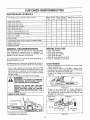
CUSTOMER
MAINTENANCE
RESPONSIBILITIES
SCHEDULE
,,_,,,,........
Befo re
Use
Fill in dates as you complete regutar service
Every Every I YeariY Service Dates
5 Hr& 25 Hrs.
After
Use
i
Check chain tension
,z
Check chain sharpness
./
, i
, ,, .,,,
....
,/,
Check guide bar condition
, ,,,,,,,,, .........
,./
Check guide bar lube
i
,, ,,,,,
Check for loose fasteners & parts
,, ,,,,
,/
Check for damaged or worn parts
i .....
,/
Clean unit & labels
....
|,,
€"
Clean air filter
Cleanlinspect spark arrestor screen & inspect muffler
',/"""'I
Replace spark plug
,/'
i
Reptace fuel filter
GENERAL
i
BEFORE EACH USE
RECOMMENDATIONS
•
•
o
°
,
The warranty on this unit does not cover items that have
been subjected to operator abuse or negligence. To
receive full value from the warranty, the operator must
maintain unit as instructed in this manual.
Some adjustments witf need to be made periodically to
properly maintain your unit
All adjustments in the "Service and Adjustments" section of
this manual should be checked at least once each season
Check
Check
Check
Check
Check
Check
chain tension
chain sharpness
guide bar condition
guide bar lube
for Ioose fasteners & parts
for damaged or worn parts
CHAIN TENSION
= Use the screwdriver end of the bar tool to move chain
around the guide bar.
o If chain does not rotate, it is too tight - slightly loosen
bar clamp nuts and turn adjusting screw 1/4 turn counterclockwise Retighten bar clamp nuts.
o If chain is too loose, it will sag below the guide bar
Figure 29.
• Once a year, replace the spark plug, replace air filter
element and check guide bar and chain for wear A new
spark plug and a clean/new air filter element assures
proper air-fuel mixture and helps your engine run better
and last longer
• Follow the maintenance schedule in this manual
WARNING
DlSCONNECTTHE SPARK PLUG BEFORE
PERFORMING MAINTENANCE EXCEPT
FOR CARBURETOR ADJUSTMENTS.
i
INSPECT THE ENTIRE UNIT. REPLACE
DAMAGED PARTS. CHECK FOR FUEL
LEAKS AND MAKE SURE ALL FASTEN.ERS ARE IN PLACE AND SECURELY FASTENED.
LUBRICATION
Sag
Figure 29
° If chain is too loose, refer to "Chain Adjustment."
Loosen bar clamp nuts; then, turn adjusting screw 1/4
turn clockwise. Lift up tip of guide bar to check for sag.
Retighten bar clamp nuts..
CHART
Adjusting
©BarOilFillCap
L_
Screw
114 Turn
I
1
Guide Bar
Clamp
Nuts
(9 Craftsman
® Craftsman
chain saw bar oil
bar sprocket lube
Figure 30
-19-
CUSTOMER
RESPONSiBILITiES
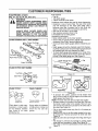
SHARPENING
CHAIN
(Fig. 31, 32, 33, 34, 35, 36 & 37)
_
IMPROPER CHAIN SHARPENING TECHARNING
NIQUES AND!OR DEPTH GAUGE MAINTENANCE WILL INCREASE THE CHANCE
OF KICKBACK WHICH CAN RESULT IN
SERIOUS INJURY,
ALWAYS WEAR GLOVES WHEN HANDLING THE CHAIN,, THE CHAIN CAN BE
SHARP ENOUGH TO CUT YOU EVEN
THOUGH IT IS TOO DLILL TO CUT WOOD°
CHAIN TERMINOLOGY & PART NAMES
Preset TheStrap
Left Hand Cutter
__='_'_Drive
Link
Right Hanc_Cut_er'-_
Tools required:
• Flat file
• .025 depth gauge
o 4.Smm round file & file holder
Conditions which indicate the need for chain sharpening:
, Reduction in size of wood chips The size of the wood
chip will decrease as the chain gets duller until it
becomes more like a powder than a chip, Note that
dead or rotted wood will no! produce a good chip.,
• Saw cuts to one side or at an angle.
° Saw requires excessive force to cut.
• Noticeable loss of cutting speed.
Sharpening instructions:
• Move on/stop switch to the "stop" position.
• Check chain for proper tension. Adjust chain tension if
necessary. (See Chain Tension/Adjustment).
• Check and Iower depth gauges before sharpening cutters.
• Depth gauges should be checked every third sharpening.When cutting frozen wood the depth gauges should
be checked each time you sharpen the chain.
• To check depth gauge, place gauge tool on cutter. If the
depth gauge projects above the tool, then file it level to
the top of the depth gauge tool. See Figure 31.
_"
Guard Tie Strap
CHAIN CUTTER PART NAMES
Top Plate -T....._=_Guitet
Side Plate _j-_,_,_Depu_n
Heet.-_.
,025"
_},_
Toe _,,, ,#
CHAIN "PITCH"
Figure 31
e
_io_et
CHAIN "GAUGE"
Right Way
This distance
divided by two
Pitch refers to chain measurement A chain's pitch
is the distance between
any three of its riveis
divided by two.
Squared
Off Corner
Thickness o! boIIorn _
section of drive tink
Gauge refers to thickness
of that portion of drive link
which fits into saw bar
groove
Wrong Way
Figure 32
• To sharpen the cutters, position the file holder level
(90°) so that it rests on the top edges of the cutter and
depth gauge. See Figure 33.
NOTE: The chain has both left and right hand cutters
• Sharpen cutters on one side of the chain first. File from
the inside of each cutter to the outside. Then turn your
saw around and repeat the process for the other side of
the chain See Figure 34
= File on the forward stroke only Use 2 or 3 strokes per
cutting edge.
o Keep the 25° line on the file holder parallel to the center of the chain Reverse procedure for other side See
Figure 35.
o
Keep all cutters the same length when filing. See Figure
36
o
File enough to remove any damage to cutting edges
(side plate and top plate) of cutter. See Figure 36
o
File chain to meet the specifications shown below. See
Figure 37.
- 20 -
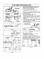
CUSTOMER
RESPONSIBILITIES
I FULL VIEW ]
FRONT VIEW ]
SIDE VIEW ]
File Holder
Cutter
Guide Bar
& Chain
Depth Gauge
Figure 33
GUIDE BAR MAINTENANCE
(Fig. 38 & 39)
Conditions which require guide bar maintenance:
• saw cuts to one side or at an angle,,
• saw has to be forced through the cut
• inadequate supply of oil to the bar and chain,,
Check the condition of the guide bar each time the chain
is sharpened, A worn guide bar wilt damage the chain
and make cutting difficult.
° Move on/stop switch to the "stop" position_
• Remove bar and chain from saw
• Clean all saw dust and any other debris from the guide
bar groove and guide bar lubrication hole, Figure 38,
• Lubricate guide bar sprocket hole after each use
Figure 38.
• Burring of bar rails is a normal process of guide bar rail
wear, Remove these burrs by filing guide bar rail side
edges square with a flat file. Figure 39,
• Restore square edges to an uneven rail top by filing
with a flat file, Figure 39,
Remove Sawdust
From Guide Bar Groove
Outside
_
""_
'--'-Inside
Sprocket Hole
CRRFTSMRB.
Figure 34
°
Figure 38
Replace the guide bar when:
- the inside groove of the guide bar rails is worn.,
. the guide bar is bent or cracked,
• excess heating or burring of the rails is noted,
Figure 35
Cutters Same
Remove Damage
Side Plate
+
If replacement is necessary, use only the replacement
reduced kickback guide bar specified for your saw in the
repair parts list or as specified on the replacement bar
and chain decal located on the chain saw.
Top Plate
Figure 36
Correct
Groove
Worn Grooves
....
Figure 39
25 °
Figure 37
-21 -
File Edges
Square ......
CUSTOMER RESPONSIBILITIES
CHECK FOR DAMAGED/WORN
PARTS
The following damaged/worn parts should be referred to
your Sears Serv{ce Center,
NOTE: It is normal for a small amount of oil to appear
under the saw after engine stops Do not confuse this with
a leaking oil tank,.
= On/Stop Switch - ensure on/stop switch functions properly by moving the switch to the "stop" position and
assure that engine stops, then restart your engine and
continue.,
= Fuei Tank - discontinue use of chain saw if fuel tank
show signs of damage or leaks,
. Oil Tank - discontinue use o! chain saw if oil tank shows
signs of damage or leaks.
= Chain Catcher - replace chain catcher if bent, cut, or
damaged in any way.
CLEAN
REPLACE
SPARK PLUG (Fig. 41)
The spark plug should be replaced each year to ensure
the engine starts easier and runs better, Spark plug gap
should be .025".
• Loosen 3 screws on cylinder cover.
• Remove cylinder cover
o Twist, then pull off the spark plug boot..
• Remove spark plug from cytinder and discard.
• Replace with correct spark plug and tighten with a 3/4"
socket wrench (10-12 Ib-ft),,
• Reinstall spark plug boot,
• Reinstall cylinder cover and 3 screws (15-20 in-lb).
Screws
Cylinder
_over
UNIT AND LABELS
. Clean the unit using a damp cloth with a mild detergent
• Wipe off the unit with a clean dry cloth,
CLEAN
AIR FILTER (Fig. 40)
CRnFT_;MRN.
A dirty air filter decreases the life and performance of the
engine and increases fuel consumption and harmful
emissions
Figure 41
Always clean your air filter after 15 tanks of fuel or 5 hours
of operation, whichever is less. Clean more frequently in
dusty conditions. A used air filter can never be completely
cleaned,, it is advisable to replace your air filter with a new
one alter every 50 hours of operation, or annually,
whichever is less.
INSPECT MUFFLER AND SPARK ARRESTOR
SCREEN (IF INSTALLED) (Fig. 42)
.
°
•
.
Required cleaning is every 25 hours of operation or annually, whichever is less
Loosen 3 screws on cylinder cover.
Remove cylinder cover,
Remove air filter
Clean the air filter using hot soapy water. Rinse with
clean cool water and air dry completely prior to reinstalling.,
• Reinstall air filter,
. Reinstall cylinder cover and 3 screws (15-20 in-tbs).
As the unit is used, carbon deposits build up on the muffler and spark arrestor screen (if installed), and must be
removed to avoid creating a fire hazard or affecting
engine performance
Replace the spark arrestor screen if breaks occur.,
CLEANING THE SPARK ARRESTOR SCREEN
. Loosen and remove the 2 muffler cover screws
• Remove the muffler cover (cover snaps intomuffler body)
= Remove muffler diffuser and spark arrestor screen assembly,Notice the orientation of these parts for reassembly
• Clean the spark arrestor screen with a wire brush or
replace if breaks are found in the screen
• Replace any broken or cracked parts
• Reinstall diffuser and spark arrestor screen assembly
with round holes facing up and towards muffler cover
• Reinstall muffler cover and 2 screws (7-8 ft-lbs),
Screws
Carburetor
Cover
/
Muffler Diffuser/
Spark Arrestor
Screen
.._,
Air Filter
Screws
Muffler
Cover
Muffler
Cover
Screws
Air
Filter
Figure 40
Figure 42
- 22 -
CUSTOMER
RESPONSIBRLITIES
REPLACE FUEL FILTER (Fig. 43_ 44 & 45)
The fuel filter should be replaced after each season
Never operate your saw withoula fuel filter Be careful not
to damage fuel line while removing the fuel filter
Pliers
o Run fuel tank dry of fuel before proceeding with this
step
, Remove fuel cap and allow it to hang to side of motor
• Using a small pair of needle nose pliers, grasp fuel cap
retainer, holding }t in tank opening and pull out.
• Wilh cap out of tank, use a smell section ol bent wire
similar to that shown in the illustration 1o calch fuel fine
and slowly pull from tank.. When fuel filter appears in
opening, grasp with fingers and remove from tank.
,, Once filter is out of tank, hold fuel line close to fuel filter
Remove fuel filter by twisting and pulling at the same
time
,, Replace fuel filter
- Reverse process for installation
.if3_.._
1
---_
Figure 43
Bent Wire.---_ . tt
_....
Figure 44
Fuel Filter
Fuel Line
Fuet Filter
I
Barret
_1
Fiiter Neck/__
Figure 45
- 23 -
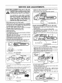
SERVICE
CHAIN
REPLACEMENT
AND ADJUSTMENTS
(Fig. 46, 47, 48 & 49
handling chain. The chain is sharp and
CAUTION:
gloves
when
can cut youWear
even protective
when it is not
moving.
- Install bar clamp nuts and finger tighten onlyo Do not
tighten any further at this point
Now proceed to the "Chain Adjustment" section.,
It is normal for a new chain to stretch.
Because of this initial stretch during the
first 15-30 minutes of operation you
should recheck your chain tension frequently and adjust the chain tension as
required. See chain tension section.
. Move orVstop switch to the "Stop" posilion.
• Replace the old chain when it becomes worn or damaged.,
. Use only the Low-Kickback replacement chain specified in
the repair parts list or as specified on the replacement bar
and chain decal located on the chain saw
• See your Sears Service Center to replace and sharpen
individualcutters for matching your chain.
• Loosen and remove the 2 bar clamp nuts,,
o Remove bar clamp
• Remove the old chain,
= Turn adjusting screw by hand counterclockwise until adjusb
ingpin just touches the stop
• Slide guide bar behind clutch drum until guide bar stops
against the clutch drum sprocket.
,, Carefully remove new chain from package. Hold chain with
the drive links as shown in Figure 47
', Place chain over and behind the clutch.
• Fit bottom of drive links between teeth in sprocket nose.
= Fit chain drive links intotop of guide bar, Figure 47
Bar Clamp Nuts
Figure 49
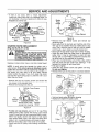
CHAIN ADJUSTMENT
€:"e",._----
Bar Clamp Nuts
& 53)
: Assure bar clamp nuts are loosened (finger tight).
Turn adjusting screw clockwise until chain just barely
touches the botlom of guide bar.,
• Roll chain around guide bar to ensure all links are in bar
groove,
FTSMRN.
Bar Clamp Nuts
Bar Clamp
(Fig, 50, 51,52
• Roll chain around guide bar to ensure kinks do not exist
(rotates freely).
\
Adjusting Screw
Guide Bar
Figure 50
• Lift up tip of guide bar to check for sag, release tip of
guide bar, then turn adjusting screw 1/4 turn clockwise.
Repeat this step until a sag does not exist
° While lifting tip of guide bar, tighten bar clamp nuts with
the bar tool (provided)., Torque 10-15 fHbs
Adjusling
Screw
Guide Bar
Figure 46
Cutters
Depth Gauge
114 Turn
Bar Tool----Clamp
Nuts
Figure 47
• Pull guide bar forward until chain is snug in guide bar
grooves
• Now, install bar clamp making sure the adjusting pin is
positioned in the lower hole in the guide bar
Bar
,
Guide
Adjusting /Pin /
/
Figure 51
To check chain tension:
• Use the screwdriver end of the bar too!
around the guide bar (Fig 53)
° If chain does not rotate, it is too tight bar clamp nuts and turn adjusting screw
terclockwise. Retighten bar clamp nuts
o If chain is too loose, it will sag below
(Figure 52),
Lower Hole
Figure 48
Figure 52
to move chain
slightly loosen
!/4 turn counthe guide bar
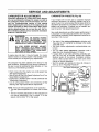
SERVICE
AND ADJUSTMENTS
• If chain is too loose, refer to "Chain Adjustment?
Loosen bar clamp nuts; then, turn adjusting screw 1/4
turn clockwise Lift up tip of guide bar to check for sag
Retighten bar clamp nuts,
Notch
Pulley
Starter
Rope
Handle
Guide Bar
Pulley
Bar Clamp
Nuts
Adjusting
Screw
Bar
Tool
Figure 53
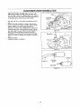
STARTER
(Fig.
ROPE
REPLACEMENT
54, 55, 56, 57 & 58)
ALWAYS WEAR EYE PROTECTION WHEN
WARNING:
SERVICING THE STARTER ROPE. THE
RECOIL SPRING BENEATH THE PULLEY
IS UNDER TENSION. IFTHE SPRING POPS
OUT, SERIOUS INJURY CAN RESULT.
Replace a broken starter rope or one that is badly frayed.
NOTE: A recoil spring lies beneath the pulley and is
under tension tf the recoil spring is disturbed, considerable time and effort will be required to reinstall. For
this reason you may want to let your Sears Service
Center handle this repair If you try to repair the starter
rope and the recoil spring pops out, take the unit to your
Sears Service Center.
Pulley Ratchet
Figure 55
• Remove the rope retainer screw and remove any
remaining rope
o Move away from the fuel tank and melt the end of the
new rope to be installed. Allow the melted end to drop
once Then, while the rope is still hot, pull the melted
end through a rag to obtain a smooth pointed end
, Feed rope through starter rope hole in starter housing.
, Guide the rope inside the pulley, then up through the
pulley, hole. It may be necessary to push the rope
through with a small Phillips screwdriver inserted into
the small hole on the underside of the pulley
- Wrap rope counterclockwise around the pulley ratchet
and tuck loose end back under rope, leaving a 1" tail
between the retainer rib and screw post.,
• Pull rope to tighten.
° Install the rope retainer screw and tighten until snug.
Do not over4ighten.
• Rewind all the rope onto the pulley in a clockwise direction.
Starter.
_-__
Housing "__
o Remove the four fan housing screws and loosen the
two screws on the cylinder cover.
o Remove fan housing from the unit
tl
Cylinder Cover Screws
,
.
Spring",x
_.e/
Figure 56
,, Twist and push pulley into starter housing.
- RepIace and tighten the pulley screw.
Screw
"
_'_--_',.
_'="
Starter Rope Pufley HOUsing
(Inside Fan Housing) Screw
Rope
._
Retainer
Screw
Figure 54
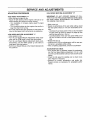
,, To take out rope tension, pull out 10" of rope While
holding down pulley ratchet with thumb, push several
inches of rope back into ian housing and catch in notch
Either hold pulley ratchet with thumb or hold starter
rope handle Retain rope in the notch and slowly allow
pulley to turn counterclockwise until tension is gone.
° Remove the pulley screw in the center of the pulley,
. Gently twist and lift pulley while rotating counterclockwise
Po,,ey-"
o
Notch
Figure 57
- 25 -
o
Screw
SERVICE
AND ADJUSTMENTS
• Pull out 10" of rope and catch rope in notch in the
pulley.
. Carefully turn the puiley two complete turns clockwise,
keeping the rope against the notch to wind the spring,,
. While holding the pulley ratchet, pull the excess rope
through the starter rope hole, While holding tension on
the rope, let rope slowly rewind into the housing,
L_
\
____/
Wind Up Spring
11(
Rewind for
Tension
Figure 58
- 26 -
• Reinstall fan housing by aligning the fan housing to the
chassis.Then white holding the fan housing against the
chassis, pull lhe rope handle out until you feel the fan
housing drop into place against the chassis. Slowly, let
the rope rewind into starter housing
• Reinstall the 4 fan housing screws and tighten the 2
cylinder cover screws Figure 54.
SERVICE AND ADJUSTMENTS
CARBURETOR
ADJUSTMENTS
Carburetor adjustment is critical and if done improperly can permanently damage the engine as welt as
the carburetor, Please read all instructions and consult the Troubleshooting
section of this manual
before beginning this process, If the engine does not
operate according to these instructions after repeating the adjusting steps, do not use the unit. For further assistance, please call our customer assistance
hottine at 1-800-235-5878,
WARNING:
THE CHAIN WILL BE MOVING DURING
MOST OF THIS PROCEDURE. WEAR
YOUR PROTECTIVE EQUIPMENT AND
OBSERVE ALL SAFETY PRECAUTIONS,
IN "LOW SPEED MIXTURE ADJUSTMENT;' RECHECK IDLE SPEED AFTER
EACH ADJUSTMENT. THE CHAIN MUST
NOT MOVE AT IDLE SPEED.
If engine does not start, it may be flooded If in doubt,
read the section on flooded engine in the starting section
of this manual prior to beginning any adjustments.
The carburetor has been adjusted at the lactory for sea
level conditions. Adjustments may become necessary if
the saw is used at significantly higher altitudes or if you
notice any of the following conditions:
CARBURETOR
PRESETS
(Fig. 59)
If your engine will not start due to suspected improper
carburetor adjustment, the following presets may be required If used, it is recommended that all steps within the
adjustment procedure be completed in order to assure a
properly set carburetor, if presets are not needed, proceed to section "Idle Speed Adjustment"
Very small adjustments can affect engine performance. It
is important to make slight adjustments and test performance before proceeding. Each adjustment should be no
more than 1/16 of a turn.
• Turn both of the mixture adjustments clockwise until
they stop Do not overtighten as damage to the needle
seats will occur
• Turn both mixture adjustments counterclockwise one
full turn,
° Turn the idle speed adjustment
clockwise until it
stops. Now turn counterclockwise 4-1/2 turns
- if engine fails to start after performing carburetor presets, the unit may be floode& Review the "Difficult
Starting" section of the manual, if problems continue
call the 1_800 number listed on the front cover of this
manual for further assistance
• Start the engine and operate for three (3) minutes to
warm up Go to "Adjusting Procedure,
idle Speed Adjustment
. Chain moves when the engine runs at idle speed. See
"Idle Speed Adjustment!'
o Saw will not idle. See "Idle Speed Adjustment" and "Low
Speed Mixture Adjustment_'
• Engine dies or hesitates when it should accelerateSee
"Acceleration Adjustment."
° Loss of cutting power which is not corrected by air filter
cleaning.. See "High Speed Mixture Adjustment.,'
\\
/
/\
Mixture
\__i_Adjustment
_/ i
NOTE: There are three adjustments on the carburetor.
• The Idle Speed Adjustment is marked with the letter
• The two remaining adjustments on the carburetor are
the mixture adjustments. One is marked "L:' for low
speed, and the other"H" for high speed
_'_H,_
"_l_..,._
_i
_l_
__
-'-_._..__
_' _-"_
HighSpeed
.Mixture
_
_
(._
Adjustment
Figure 59
- 27 -
l
}
SERVICE
ADJUSTING
AND ADJUSTMENTS
PROCEDURE
IDLE SPEED ADJUSTMENT "T"
"Aliow the warm engine to idle
• Adjust the Idle Speed until the engine continues to run
without stalling and without the chain moving.
- Turn clockwise to increase engine speed if engine
stalls or dies.
- Turn counterclockwise to slow engine down and/or to
keep the chain from turning
• No further adjustments are necessary if chain does not
move at idle speed and if performance is satisfactory
LOW SPEED MIXTURE ADJUSTMENT "U'
• Allow engine to idle
, Turn the Low Speed Mixture Adjustment slowly clockwise until the RPM starts to drop. Note the position.
, Turn the Low Speed Mixture Adjustment slowly coum
terclockwise until the RPM speeds up and starts to
drop again. Note the position,
. Set the Low Speed Mixture at the midpoint between the
two positions.
HIGH SPEED MIXTURE ADJUSTMENT "H"
IMPORTANT: DO NOT OPERATE ENGINE AT FULL
THROTTLE FOR PROLONGED PERIODS WHILE MAKING HIGH SPEED ADJUSTMENTS AS DAMAGE TO
THE ENGtNE CAN OCCUR.
• Make a test cuL
• Based on performance of the saw while cutting, adjust
the high speed mixture in 1/16 turn increments as follows:
- Clockwise if saw loses power in the cut. Do not adjust
for best power by sound or speed, but judge by how
well the saw performs in the cut.
- Counterclockwise ff the saw has speed while out of
the cut, but dies in the cut or lacks power while cutting_
o Repeat the lest cut.
° Continue with 1/16 turn adjustmenls until the saw performance is acceptable while cutting
• After completing adjustments, check for acceleration°
ACCELERATION CHECK
• If the engine dies or hesitates instead of accelerating,
turn the Low Speed Mixture Adjustment 1/16 of a turn
at a time counterclockwise until you have smooth acceleration.
= Check the idle speed for stability and no chain movement. Adjust as necessary..
o Recheck for smooth acceleration and stable idle
Repeat process as necessary for acceptable performance.
28 -
STORAGE
Immediately prepare your unit for storage at the end of
the season or if it wilt not be used for 30 days or more.
_
ALLOW
THE ENGINE '10 COOL, AND
ARNING:
SECURE THE UNIT BEFORE STORING
OR TRANSPORTING IN A VEHICLE,
STORE UNIT AND FUEL IN AN AREA
WHERE FUEL VAPORS CANNOT REACH
SPARKS OR OPEN FLAMES FROM
WATER HEATERS, ELECTRIC MOTORS
OR SWITCHES, FURNACES, ETC.
Fuel stabilizer is an acceptable alternative in minimizing
the formation of fuel gum deposits during storage. Add
stabilizer to the gasoline in the fuel tank or fuel storage
container Always follow the mix instructions found on stabilizer containers Run engine at least 5 minutes after
adding stabilizer to allow the stabilizer to reach the carburetor
STORE UNIT WITH ALL GUARDS IN
PLACE, POSITION SO THAT ANY SHARP
OBJECT
CANNOT
ACCIDENTALLY
CAUSE INJURYTO PASSERS BY.
STORE THE UNIT OUT OF THE REACH
OF CHILDREN.
CRAFTSMAN 40:1 2-cycle engine oi! (AIR-COOLED) is
specially blended with fuel stabilizer If you do not use this
Sears oil, you can add a fuel stabilizer to your fuel tank.
WEAR
PROTECTIVE
GLOVES WHEN
HANDLING CHAIN.THE CHAIN tS SHARP
AND CAN CUT YOU EVEN WHEN IT IS
NOT MOVING,
GAS CHAIN
INTERNAL
SAW STORAGE INSTRUCTIONS
If your chain is to be stored for a period of time, clean it
thoroughly prior to storage Remove any dirt, sawdust,
ieaves, oil, grease, etc. Store in a clean dry area.
,' Clean the entire unit..
. Clean air filter. Refer to "Customer Responsibilities."
. Inspect the bar clamp area and clean any dirt, sawdust,
grass, or debris that has collected. Inspect the guide
bar and chain; replace a guide bar that is bent, warped,
cracked, broken, or damaged in any other way_Replace
a damaged or worn chain.
,' Lightly oil external metal surfaces to prevent rust from
forming
o Apply a coating of oil to the entire sudace of the guide
bar and chain; wrap it in heavy paper, or cloth.
° Be sure all handles and guards are in place and are
securely fastened. Replace any damaged parts
ENGINE
= Remove spark plug and pour 1 teaspoon of 40:! 2cycle engine oil (AIR-COOLED) through the spark plug
opening. Slowly pull the starter rope 8 to 10 times to
distribute oil to inner engine surfaces.
. Replace spark plug wilh a new one of the recommended type and heat range. Refer to "Product Specifications."
• Clean air filter Refer to "Customer Responsibilities.."
° Re-install all covers and hardware removed for access;
tighten all screws and fasteners.
,, Check entire unit for loose screws, nuts, and bolts.
Replace any damaged, broken, or worn parts.
- Lightly oil external metal surface to prevent rust from
forming.
• Use fresh fuel having the proper gasoline to oil ratio at
the beginning of the next season.
OTHER
- Do not store gasoline from one season to another.
o Replace your gasoline can if your can starts to rusL Rust
and/or dirt in your fuel system wilt cause problems.
* Store your unit in a well ventilated area and covered, if
possible, to prevent dust and dirt accumulation Do not
cover with plastic. Plastic cannot breathe and will
induce condensation and eventual rust or corrosion
FUEL SYSTEM
Never use engine or carburetor cleaner products in the
fuel tank or permanent damage may occur to fuel system
components Follow these instructions:
o Drain the luel from the unit into an approved fuel container,
- Drain the fuel lines and carburetor by starting
engine and letting it run until it stops.
,' Allow the engine to cool before storage.
IMPORTANT: It is important to prevent gum deposits
from forming in essential fuel system parts such as the
carburetor, fuel filter, fue! hose or tank during storage
Also, experience indicates that alcohol blended fuels,
those that use ethanol or methanol (called gasohol or
oxygenaled fuel), can attract moisture and form acidic
gas which will damage your engine .To avoid engine problems, the fuel system should be emptied before storage
of 30 days or longer.
the
IMPORTANT: NEVER COVER UNIT WHILE
AND EXHAUST AREAS ARE STILL WARM
- 29 -
ENGINE
TROUBLE SHOOTING POINTS
TROUBLE
SHOOTING
CHART
SYMPTOM
CAUSE
CORRECTION
Engine will not start
or wilt run only for
a few seconds
after starting.
I Fuel tank empty.
2. Engine flooded.
3. Spark plug not firing.
4, Fue! not reaching carburetor,
5. Carburetor requires adjustment.,
6. Stop switch off
7o None of the above.
Engine will not idle
properly
1. Idle speed set too fast or too slow.
2_ Low speed mixture requires adjuslment
3. Crankshaft seals worn.
4, Compression low
5. None of the above.
1. Fill tank with correct fuel mixture
2 See "Starting Instructions."
3. Install new plug/check ignition switch
4. Replace fuel filter; inspect fuel tine
5, See "Carburetor Adjustments."
6. Move switch to the "START" position.
7, Contact your Sears Service CentedDept
!. See "Carburetor Adjustments"
2, See "Carburetor Adjustments."
3 Contact your Sears Service Center/Dept_
4. Contact your Sears Service Center/Dept.
5, Contact your Sears Service Center/Dept.
Engine will not
accelerate, lacks
power, or dies
under a load.
1. Air filter dirty,
2. Spark plug fouled
3. Carburetor requires adjustment_
4. Exhaust ports or muffler outlets plugged
5 Compression low.
6. None of the above.,
t. Clean or replace air filter.
2_ Clean or replace spark plug and re-gap.
3 See "Carburetor Adjustments._'
4. Contact your Sears Service CentedDepto
5. Contact your Sears Service Center/DepL
6. Contact your Sears Service Center/Dept,
Engine smokes
excessively
1_ Air filter dirty,
2, Fuel mixture incorrect,
3. High speed mixture requires adjustment
4. Choke partially on
1.
2,
3.
4
Engine runs hot°
1, Fuel mixture incorrect.
2., High speed mixture set too low (Lean),
3. Spark plug incorrect.
4 Exhaust ports or muffler outlets plugged r
5. Carbon build-up on muffler outlet screen.
6, Fan housing/cylinder fins dirty.,
7. None of the above.
Oil inadequate for bar
and chain lubrication.,
t. Oil tank empty.
2,, Oil pump or oil filter clogged
3. Guide bar oi! hole blocked,
Chain moves at
idle speed.
Chain does not move
when engine is
accelerated.
1. Idle speed requires adjustment
2. Clutch requires repair
Chain clatters or
cuts roughly
Chain stops within
the cut.
Clean or replace air filler.
Refuel with correct fuel mixture.
See "Carburetor Adjustments."
Push choke knob in.
See "Fueling Your Unit?
See "Carburetor Adjustments?
Replace with correct plug.
Contact your Sears Service Center/Dept.
Clean spark arrestor screen
Clean area.
Contact your Sears Service CentedDept,
I Fill oil tank
2, Contact your Sears Service Center/Dept.
3. Remove bar and clean.
!.
2.
3.
4.
5.
6.
7-
See "Carburetor Adjustments.._'
Contact your Sears Service Center/Dept.
See "Chain Tension;'
See "Carburetor Adjustments."
Repair or replace.
Contact your Sears Service Center/Dept.
See "Chain Tension"
Contact your Sears Service Center/Dept
Resharpen or replace chain
Have chain sharpened
1. Chain tension too tight.
2, Carburetor requires adjustment,
3. Guide bar rails pinched.
4. Clutch slipping
1., Chain tension incorrect.
2. Cutters damaged,
3, Chain worn.
4 Cutters dull, improperly sharpened, or
depth gauges too high,
5. Sprocket worn.
6 Chain installed backwards.
1,
2.
3,
4,
1.'Chain cutter tops not filed flat.r
2 Guide bar burred or bent; rails uneven.
3. Clutch slipping
1 Have chain sharpened
2. Repair or replace guide bar.
3. Contact your Sears Service CenteriDepL
Chain cuts at an
angle,
g,
4_
5. Contact your Sears Service Center/Dept
6 Install chain in right direction.
1. Cutters damaged on one side.
1. Have chain sharpened
2. Chain dull on one side.
2, Have chain sharpened
3. Guide bar bent or worn.
3. Replace guide bar,
If situatiohs occur which are not covered in this manua use care and good judgement
If you need assistance, contact your SEARS Service Center/Department or the
CUSTOMER ASSISTANCE HOTLINE at 1-800-235-5878.
30