1
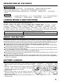
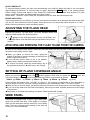
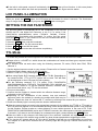
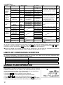
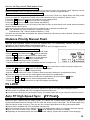
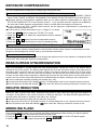
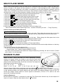
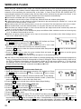
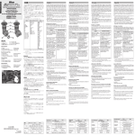
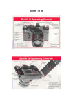
ENGLISH Thank you very much for purchasing the Sigma EF-530 DG SUPER NA-iTTL Electronic Flash. This product is specifically developed for the Nikon SLR series cameras. Depending on the camera model, functions and operation may vary. Please read this instruction booklet carefully. To add to your enjoyment of photography, this flash has a variety of features. To make the most of all these features and to get the maximum performance and enjoyment from your flash, please read this instruction booklet together with your camera’s instruction manual, before using the flash and also keep it handy for your future reference. PRECAUTIONS In order to avoid causing any damage or injury, please read this instruction manual very carefully, paying attention to the cautionary signs below, before using the flash. Please take special note of the two cautionary signs below. Warning !! Using the product disregarding this warning sign might cause serious injury or other dangerous results. Using the product disregarding this caution sign might cause injury or damage. Symbol denotes the important points, where warning and caution are required. Symbol contains information regarding the actions that must be avoided. Caution!! Warning !! This flash contains high voltage circuits. To avoid electric shock or burns, do not attempt to disassemble the flash. If the outside shell of the unit is broken or cracked, do not touch the mechanism inside. Do not fire the flash close to eyes. Otherwise the bright light could damage the eyes. Keep at least 1m/3feet distance between face and the flash unit when taking a picture with flash. Do not touch the synchro terminal of your camera when the flash is attached to a hot shoe. High voltage circuitry could cause an electric shock. Never use your camera in an environment where flammable, burnable, gas, liquids or chemicals, etc, exist. Otherwise it might cause fire or explosion. Caution !! Do not use this flash unit on any camera other than the Nikon NA series cameras, otherwise the flash may damage the circuitry of these cameras. This flash unit is not waterproof. When using the flash and camera in the rain or snow or near water, keep it from getting wet. It is often impractical to repair internal electrical components damaged by water. Never subject the flash and camera to shock, dust, high temperature or humidity. These factors might cause fire or malfunctioning of your equipment. When the flash is subjected to sudden temperature change, as when the flash unit is brought from a cold exterior to warm interior, condensation might form inside. In such a case, place your equipment in a sealed plastic bag before such a change, and do not use the flash unit until it reaches room temperature. Do not store your flash in a drawer or cupboard etc. containing naphthalene, camphor or other insecticides. These chemicals will have a negative effects on the flash unit. Do not use a thinner, Benzene or other cleaning agents to remove dirt or finger prints from the component. Clean with a soft, moistened cloth. For extended storage, choose a cool dry place, preferably with good ventilation. It is recommended that the flash be charged and fired several times a month to maintain proper capacitor functioning. 13 DESCRIPTION OF THE PARTS EXTERNAL PARTS 1.Flash Head 2.Built-in Wide Panel 3.AF Auxiliary Light 4.Bounce Angle; Up and Down 5.Bounce Angle; Right and Left 6.Bounce Lock and Release Button; Up and Down 7.Swivel Lock and Release Button; Right and Left 8.LCD Panel 9.Battery Cover 10.Shoe Ring 11.Shoe CONTROLS 12.MODE Button 13.<SEL> SELECT Button 14.< + > Increment Button 15.< - > Decrement Button 16.ZOOM Button 17.TEST Button 18.LIGHT Button 19.Ready Light 20.Power Switch CAMERA MODELS AND FUNCTIONS This flash can be used with cameras, which are given below. D2 Series, D200, D80, D70s, D70, D50, D40X, D40, D1 Series, D100, F6, F5, F4 Series, F3 Series(*), F100, F90X/N90S Series, F90/N90 Series, F80 Series, F75/N75, F70D/N70, U/F65/N65, F60D/N60, F55/N55, F50D/N50, F-801S/N8008S, F-801/N8008, F601M, F-601/N6006, F501/N2020, F401X, F401S/N4004S, F-401/N4004, F-301, N2000, FA, FE10, FE-2, FG, FM10, New FM2, FM3, Nikonos V(*), Pronea 600i (*) It is necessary to use adapter for connection. This instruction book is used for the following lens types. (Please check your lens.) With Built-in CPU Nikon Lenses D Type Lenses, G Type Lenses, IX Nikor Lenses, Except D type AF lens (does not include F3AF), Ai-P type lens Without Built-in CPU Nikon Lenses Ai-S, Ai, Series E lens ABOUT THE BATTERY This flash unit uses four “AA” type Alkaline dry cell batteries or Ni-Cad, Ni-MH rechargeable batteries. Manganese batteries can also be used but as they have a shorter life than Alkaline batteries, we do not recommend using them. Please replace batteries if it takes more than 30seconds to light the Ready Lamp. ◆ To assure proper electrical contact, clean the battery terminals before installing the batteries. ◆ NiCad batteries do not have standardized contacts. If you use NiCad batteries, please confirm that the battery contacts touch the battery compartment properly. ◆ To prevent battery explosion, leakage or overheating, use four new AA batteries of the same type and brand. Do not mix the type or new and used batteries. ◆ Do not disassemble or short-circuit the batteries, or expose them fire or water; they may explode. Do not recharge the batteries other than Ni-Cd or Ni-MH rechargeable batteries. ◆ When the flash will not be used for an extended period of time, remove the batteries from the flash to avoid the possibility of damage from leakage. ◆ Battery performance decreases at low temperatures. Keep batteries insulated when using the flash in cold weather. ◆ As with any flash, it is recommended you carry spare batteries when on a long trip or when photographing outdoors in cold weather. BATTERY LOADING 1. Be sure to set the Power Switch to the off position then slide the battery cover in the direction of the arrow to open. 2. Insert four AA size batteries into the battery chamber. Be sure the + and – ends of the batteries are aligned according to the diagram in the chamber. 3. Close the cover. 4. Slide the Power Switch to the ON position. After few seconds the Ready Lamp will light, indicating that the flash unit can be fired. 5. Please press the “Test Button” to be sure that the flash is working properly. 14 AUTO POWER OFF To conserve battery power, the flash unit automatically turns itself off when the flash is not used within approximately 80 seconds. To turn the flash on again, depress the TEST button or the camera shutter button halfway. Please note that the “Auto Power Off” mechanism does not work with wireless TTL flash mode, normal slave flash, and designated slave flash modes. Please Note; However, “Auto Power Off” mechanism does not work with slave flash mode. ERROR INDICATION If the battery power is not sufficient, or if there is an electric information error between the camera and flash unit, the “Er” icon will blink on the LCD panel. When this occurs, turn the power switch off and on. If it still blinks, after this procedure, check the battery power. ADJUSTING THE FLASH HEAD Depress the Bounce “Up and Down” Lock and Release Button and adjust the flash head to the desired position. appears on the LCD panel when you turn on the flash, and ◆ If if this mark blinks, then the flash head is adjusted to an incorrect position. ATTACHING AND REMOVING THE FLASH TO AND FROM THE CAMERA Be sure to turn off the Power Switch, then insert the Shoe Base into the hot shoe on the camera and turn the Shoe Locking Ring until it is tight. ◆ When you attach or remove the flash, grasp the bottom of the flash to prevent damage to the shoe foot and the camera’s hot shoe. ◆ If the camera’s built-in flash is set in up position, please close it before you attach the flash unit. ◆ To remove the flash, rotate the shoe-locking ring in the opposite direction of ◄LOCK mark, until it stops. SETTING OF FLASH COVERAGE ANGLE When you press the ZOOM button, the symbol appears. Each time you press the ZOOM button, the LCD panel display will change and indicate the zoom position in sequence as follows. 24mm → 28mm → 35mm → 50mm → 70mm → 85mm → 105mm → (Auto) Please confirm the distance from <<CHART A>> page 17. If the setting is possible with 1 then depending on the focal length of the lens, the flash coverage angle will be set automatically, when TTL mode is chosen. ◆ When you turn on the main switch, the flash will memorize and set the zoom head position to the last setting used. ◆ If you use a lens wider than the flash head setting, there may be under exposed areas around the edges of the picture. ◆ Depending on the flash head setting, the flash’s Guide Number will change. WIDE PANEL This flash is equipped with a built in type wide panel, which can provide ultra wide 17mm angle of coverage. Slide out the wide panel and flip it down to cover flash’s head. Then the coverage angle setting of the flash will be set to 17mm automatically. 15 ◆ If the built-in wide panel comes off accidentally, the ZOOM button will not function. In this case please contact the store where the flash was purchased, or an authorized .Sigma service station. LCD PANEL ILLUMINATION When you press the LIGHT button, the LCD panel will illuminate for about 8 seconds. The illumination stays on longer than 8 seconds if you press the LIGHT button once again. SETTING THE ISO FILM SPEED The ISO film speed is automatically set for the combination of EF-530 DG SUPER NA-iTTL with Digital SLR Cameras, or the F-5, F-4 series, F100, F90X/F90/F80 (N90S/N90/N80) series, F75D/N75, F65/N65, F70/N70, F810S/N8008S, F801/N8008 and Pronea600i. To confirm ISO film speed, press the MODE button. If your camera is not one of the models listed above, please follow the procedure below. 1. Press the MODE button until ISO is selected. 2. Press the SEL button. The ISO value will blink. 3. Press + or – to set ISO film speed. 4. Press the SEL button and make the indicator stop blinking. TTL Mode TTL mode can provide the correct exposure for the subject and will control the amount of flash. ◆ Please refer to <<CHART A>> which shows the combinations of camera and lens types, exposure mode, and flash modes. ◆ TTL function does not work when using the following cameras: F3 series, FM10, New FM2, FE10, Nikonos V. 1. Set the desired exposure mode on your camera. Please refer to Camera’s Instruction manual. 2. Slide the Flash’s power switch to the ON position. 3. Select TTL/BL or TTL by pressing the MODE button. ◆ When using Digital SLR Cameras, please select TTL/BL. Depending on the camera model, i-TTL or D-TTL system will be used. The ”d” mark will be displayed on the LCD panel for both systems. ◆ For the following cameras; F-5, F-4 series, F100, F90X/F90/F80 (N90S/N90/N80) series, F70D/N70, F810S/N8008S, F801/ N8008S and Pronea 600i, TTL/BL or TTL can be selected. However, cameras other than those listed above, only TTL can be selected. 4. Focus on the subject. 5. Confirm that the subject is located within the effective distance range, indicated on the LCD panel. ◆ Depending on the combination of the camera, lens and selected exposure mode, the method for shooting the subject with flash may be different. Please see chart “A” and set the “F”-number by referring to the manual for your camera. 6. Confirm the Ready Light is on and press the shutter release button. ◆ When the camera does not receive the appropriate exposure for the subject, the TTL/BL or TTL mark on the LCD panel will appear for 5 seconds after shooting, which shows that the flash power is not sufficient for this situation. Please re-take at a closer distance or use a wider aperture. In the case of F5, F100, F90X/F90/F80 (N90S/N90/N80) series and F70D/N70 cameras, the underexposure indicator appears for 5 seconds. If you want to see the display for underexposure again, please depress the LIGHT button. ◆ When the flash is fully charged, the ready light in the camera’s viewfinder will appear. If it does not appear, the shutter of the camera may operate at a slow shutter speed without triggering the flash. ◆ If you use the AF camera with an AF lens, the AF Auxiliary Light will turn on automatically as you focus on a subject in a dark area. However the AF Auxiliary Light will not light up if central focus area is not selected. 16 <<CHART A>> Camera Lens Type Exp. Mode Metering F5 D, G Type All Modes F100 F90X/N90ser. AF lens other than All Modes F80/N80ser. D, G type F70D/N70 A/M Without Built in CPU F75/N75 Modes F4 Series F-801S/N8008S F-801/N8008 F65/N65 Pronea 600i F601/N6006 F-601M F60D/N60 F50D/N50 F-401X/4004S F501/N2020 F301/N2000 F401S/N4004S F401/N4004 FA, FE2 FG, F3, FM3 With Built-in CPU All Modes Without Built-in CPU A/M Modes With Built-in CPU All Modes Without Built-in CPU A/M Modes P/S A/M With Built-in CPU Without Built-in CPU Built-in CPU lens ,Ai-S, Ai, Series E, AF F3 Lens Except above lenses With Built-in CPU Without Built-in CPU With Built-in CPU; Without Built-in CPU All Modes All Modes Center-weighted, Spot Metering Matrix Pattern Center-weighted, Spot Metering Center-weighted, Spot Metering Matrix Pattern Center-weighted, Spot Metering Center-weighted, Spot Metering M P TTL System Note 3-D Multi-Sensor BL Can switch to TTL Mode. With F5, F100, F80, series Cameras Multi-Sensor BL spot metering system is always Center Weighted / TTL. Spot Fill-Flash TTL BL Can switch to TTL Mode. TTL BL Center Weighted / can work with only F4 series, AF Spot Fill-Flash F3, Ai-S, Ai, Series E lens. Spot metering system of F4 is always Center TTL. Pronea 600i will be TTL, Weighted/Spot when exposure mode is “M”. Fill-Flash Center Weighted BL cannot work. TTL BL Center Weighted / Spot Metering cannot use with Spot Fill-Flash F-601M Center Weighted / Spot Fill-Flash If exposure mode is “M”, it will be TTL BL Center Weighted/Spot Fill-Flash Center Weighted / Spot Fill-Flash TTL Programmed A/M TTL A/M TTL P/S A/M M TTL Programmed TTL TTL A/M TTL Conf Dist 1 2 1 2 2 2 2 2 2 2 2 Confirm Distance: 1 : Flash’s LCD panel will show the F-number and working distance of flash automatically. 2 : Set the F-number on the flash to be the same as camera, and check the available working distance range on the LCD panel. To set the F-number on the Flash, push the SEL button until the F-number blinks, and use + or – button to set the F-number. Then press the SEL button again. The F-number will stop blinking. ◆ When using Digital SLR cameras, functions will vary depending on the lens type and combinations of exposure modes, same as F5 and F100 group (in chart A), however, they will use D-TTL (i-TTL). LIMITS OF CONTINUOUS SHOOTING To prevent overheating of the flash’s circuitry, do not use your Flash unit for at least 10minutes after continiously using the flash as shown in the table below. Mode TTL, M(1/1,1/2) M(1/4, 1/8) M(1/16-1/32) Multi Number of Flash Exposures 15 Continuous Flash Shots 20 Continuous Flash Shots 40 Continuous Flash Shots 10 Cycle MANUAL FLASH OPERATION Manual flash is provided for shooting subjects when the correct exposure is difficult to obtain in the TTL mode. In the manual flash mode, you can set the flash power level from 1/1 to 1/64 power in 1/3 stop increments. 1. Set the camera’s exposure mode (A, M modes). 2. Press the MODE button on the flash unit to select M. 3. Press the SEL button to make the guide number value blink. 4. Press + or – button to set the desired flash power output. 5. To stop the manual flash output display blinking, Press the SEL button again. 6. When the Ready Light of the flash is illuminated, the unit is ready for use. 17 How to set the correct flash power level Page 17 <<CHART A>> combination of 1 Focus on the subject and note the subject distance on the lens’ focus ring. Adjust the lens’ aperture until the distance indicated on the LCD panel of the flash is equal to the camera to subject distance. When you use with cameras other than the above Focus on the subject and note the subject distance on the lens’ focus ring. Adjust either the flash power level or the flash’s F stop display. Please refer to the following on how to change the flash’s F-stop. 1. Press the SEL button several times and make the F-stop indicator blink. 2. Press the + button or – button to set the F-stop display. 3. Press the SEL button to make F-stop indicator stop blinking. Set the distance indicated on the LCD panel of the flash so that it is about equal to the actual camera-to-subject distance become about equal. Then set the aperture value of the lens via lens’ aperture ring or cameras command dial. ◆You can calculate the correct exposure by using this formula. Guide Number “GN” / Flash to Subject Distance = F-stop This flash unit will calculate and indicate the Subject Distance by following the above formula. (Please refer to table1 on the last page). Distance Priority Manual Flash With this flash operation system, EF-530 DG SUPER NA i-TTL automatically controls the light output according to the selected distance and aperture value. Distance-priority manual flash is not possible with D1X and D1H digital cameras. Page 17 <<CHART A>> combination of 1 1.Set the camera’s exposure mode to either A or M mode. 2.Press MODE on the flash unit so (GN) is displayed. 3.Press the SEL button to make the distance display blink. 4.Press the + button or – button to set the distance. 5.Press the SEL button several times to stop blinking. 6.Set the aperture value on the lens or camera. 7.When the Ready Light of the flash is illuminated, the unit is ready for use. When using with cameras other than the above 1.Please follow the first 2 steps as above and press the SEL button several times to make the aperture display blink. 2.Press the + button or – button to set the F-stop display. 3.Press the SEL button to stop the display blinking. 4.Set the aperture value on the lens or camera, make sure that the flashgun is charged before firing. ◆ Distance-priority manual can be used together with exposure compensation. 1.Press the SEL button several times to make the compensation amount indicator 2.Press the + or - button to set the compensation amount. 3.Press the SEL button several times to make the display stop blinking. blink. FV LOCK “FV” lock mode allows you to choose and lock the exposure for part of the image before taking the picture. ◆ This function is available with CLS compatible camera models only. ◆ You cannot set this function on the flashgun directly. For details please refer to your camera’s instruction manual. Auto FP High-Speed Sync (FP Flash) When you take a picture with an ordinary flash, you cannot use a shutter speed faster than the camera’s synchronized speed because the flash must fire when the shutter curtain is fully open. The FP flash keeps firing while the shutter curtain is running. Thus you can use a shutter speed faster than the synchronized speed. ◆This function is available with CLS compatible cameras only. ◆You cannot set this function on the flashgun directly. For details please refer to your camera’s instruction manual. will be displayed on Flash’s LCD display. ◆When you set this function on the camera, ◆ Depending on the shutter speed, the Guide Number will change. (Please refer to table2 on the last page) 18 EXPOSURE COMPENSATION You can compensate the exposure by changing the flash power level. Exposure compensation of the EF-530 DG SUPER NA-iTTL Super flash’s power level ◆ Dedicated exclusively for Digital SLR Cameras and F5, F4 series, F100, F90/N90, F90X/N90S, F80/F80 series, F70D, F75/N75, U/F65/N65, F801S/N800S, F801/ N8008, F601M, F601/N6006 and Pronea 600i only. ◆ Cameras with EV compensation capability allow you to make exposure compensation on either the EF-530 DG SUPER NA-iTTL or the camera (or both). If you use both controls, exposure is modified by the sum total of both exposure compensation values, and will affect the background exposure. ◆ If your camera is an F601 / N6006 series camera, set the exposure compensation by operating the camera’s synchronization mode. ◆ It can be set at 1/3 stop increments from +1.0 stops to –3.0 stops. 1. Press the MODE button to select the TTL/BL (TTL) mode. 2. Press the SEL button to make the compensation amount indicator blink. 3. Press the + and - button to set the compensation amount. 4. Press the SEL button several times to stop the display blinking. Exposure compensation of the EF-530 DG SUPER NA-iTTL flash’s power level and background ◆This function can be used on all Nikon cameras except F3 series, FM10, New FM2 and FE10. Use your camera’s exposure compensation control button or dial to make exposure compensation to both foreground and background. (Please refer to your camera’s instruction) Exposure compensation on M mode When using the camera on M mode, you can change the aperture value on the camera, or change the flash power level, after setting the exposure compensation. REAR-CURTAIN SYNCHRONIZATION When you photograph a moving subject with slow synchronization, usually the furrow of the subject will be exposed in front of the subject. The ordinary flash light will fire when the first shutter curtain is fully opened, thus the subject will be exposed from the time flash is fired to the time the shutter is closed (This is front curtain synchronization). When you use rear curtain synchronization, the flash will fire just before the rear curtain begins to close, and the subject will be exposed by ambient light from the time the shutter opens until the flash fires. As a result, the furrow of the subject will therefore be recorded behind the subject, creating a more natural effect. ◆ It can be used with cameras providing rear-curtain sync. only. ◆ You cannot set this function on the flashgun directly. For details please refer to your camera’s instruction manual. ◆The LCD panel on the flash will indicate mark, when the “Second-curtain synchronization” function is set. RED-EYE REDUCTION When you take a picture with flash, sometimes the person’s eyes reflect the flash light and appear as “red-eyes”, in the picture. If you use the function of “Red-eye reduction”, the flash will blink approximately 1 second, before the shutter is released, and reduce the “red-eye”. ◆ Available with cameras providing red-eye reduction control only. ◆ You cannot set this function on the flashgun directly. For details please refer to your camera’s instruction manual. ◆ The LCD panel on the flash will indicate mark, when the “Red-eye reduction” function is set. MODELING FLASH If you use the Modeling flash, you can check the lighting and shadow effects, before you take the picture. 1. Press the MODE button and select the mode you want to use. 2. Press the + button or – button several times to make the icon on the LCD panel appear. 3. Confirm that the flash is charged, then press the TEST button to fire. 19 MULTI FLASH MODE When a slow shutter speed is used, the flash will fire repeatedly while the shutter is open. By doing so a series of images of the subject will be exposed in one frame. A dark background with a bright subject shows the result more effectively in this mode. It is possible to set the firing frequency between 1Hz and 100Hz. Up to 100 flashes can be fired continuously. The maximum number of flashes varies, depending on the flash guide number and firing frequency settings. (Please refer to table3 on the last page). 1. Set the camera’s exposure mode to M and set the desired aperture. 2. Press the MODE button until the multi-flash mode appears. 3. Press the SEL button until the flash firing frequency starts to blink. 4. Press the + or – button to set the desired flash frequency value. 5. After pressing the SEL button again, the flash power level will blink. 6. Press the + or – button to set the desired power level. 7. Press the SEL button again, the number of flashes will blink. 8. Press the + or – button to set the desired number of flashes. 9. Press the SEL button until the display stops blinking. 10. When the ready light of the flash is illuminated, the unit is ready to use. Note: Please set the shutter speed longer than; Number of Flashes you want ÷ Firing Frequency How to set the correct flash power level Page 17 <<CHART A>> combination of 1 Read out the subject distance from the focus ring on the lens. Then adjust the aperture ring on the lens until the distance indicated on the LCD panel of the flash and the subject distance become about equal. When using with cameras other than the above Read-out the subject distance from the focus ring on the lens. Either change the flash power level or the flash’s F-stop. Please refer following on how to change the flash’s F-stop. 1. Press the SEL button several times to make the F-stop indicator blink. 2. Press the + or – button and set the F-stop. 3. Press the SEL button and make the indicator of F-stop stop blinking. Please set the distance indicated on the LCD panel of the flash and the actual subject distance so that they are about equal. Then set that F-stop on the lens aperture ring. * You can calculate the correct exposure by using this formula: Guide Number “GN” / Flash to Subject Distance = F-stop This flash unit will calculate and indicate the Subject Distance by following the above formula. (Please refer to table 1 on the last page) BOUNCE FLASH When you take a photo with flash in a room, sometimes a strong shadow will appear behind the subject If you point the flash head upwards or sideways to reflect the light off the ceiling, wall etc, the subject will be illuminated softly. Press the lock button and adjust the flash head to set the bounce angle. UP: 0°, 60°, 75°, 90° DOWN: 0°,7° RIGHT: 0°, 60°, 75°, 90° LEFT: 0°, 60°, 75°,90°, 120°, 150°, 180° When the bounce flash mode is activated, a bounce indicator will appear on the LCD panel. Choose a white surface for bouncing the flash, otherwise the image’s colour may be incorrect. Depending on the reflecting surface, the subject distance and other factors, the effective distance range for the TTL AUTO may change. Please check for correct exposure confirmation (TTL BL or TTL mark on the LCD panel) after releasing the shutter. Close-up Exposures Bounce flash can be tilted 7° downward for close-ups. The Flash will be effective only for the subjects 0.5 will blink. meter to 2 meters. When the flash head is tilted 7° 20 WIRELESS FLASH When using the “Wireless Flash” mode, you can take pictures with a more three-dimensional feeling with shadow, or you can produce natural images with shadow depending on the flash position without any extension cord connecting the camera body to the flash. In case of the EF-530 DG SUPER NA-iTTL, communication between the camera body and the flash will be achieved by the light of the flash. In the “Wireless Flash” mode, the camera will calculate the correct exposure automatically. ◆ This function is available with CLS compatible cameras only. ◆ It is possible to use the built-in flash of D70(D70s), D80 and D200 with wireless photography. ◆ In these instructions, we call a flash unit, which is attached to the camera body the “Master unit ”, and we call a flash unit at a remote position a “Slave unit”. ◆ When setting a slave unit at the desired position, you can use a mini-stand. This mini-stand has a screw hole for a tripod. ◆ Place the slave flash unit at the desired location. Do not place the slave unit within the picture area. ◆ Set the flash unit within the range of 0.5m/1.5ft~5m/16ft from the subject and set the camera body within the range of 1m/3ft~5m/16ft from the subject. ◆ Two or more sets of Slaves can be divided into groups and different flash conditions can be set for each group (1~3). The Master Flash should be set at 0. ◆ Channel and group number settings can be input on the master unit and slave units. Other settings can be input on the master flash unit only. Setting the slave unit 1. Attach the flashgun to the camera body and switch “ON” the flash unit. Press icon. the MODE button to select the TTL / / ◆ Setting cannot be done if camera’s exposure display turns off. In such a case, press the camera’s shutter button half-way to re-activate the setting. 2. Press the SEL button to make the channel indicator blink and press the + or – button to set the channel number (from C1- C4). 3. Press the SEL button to make the group number blink and press the + or – button to set the group number. Press the SEL button to confirm. 4. Detach the slave unit from the camera body and place it in the desired position. ◆ In the case of using D200’s(D80’s) built-in flash for wireless photography Group A cameras correspond to Group 1 flashguns and Group B corresponds to Group 2 flashguns. When using the built-in flash unit of the D70 for wireless photography, set the channel number to C3 and group number to 1. For the rest of the settings, refer to your camera’s instruction manual. Please also note that it cannot be used with D70(D70s) and D200 camera’s command mode AA and M1/128. Setting the Master Unit Setting the channel number on the master flash unit 1. Attach the flashgun to the camera body, and switch “ON” the flash unit. Press the MODE button to select the icon is shown icon. Confirm the in the display. 2. Press the SEL button to make the channel indicator blink on the display. 3. Press the + or – button to set the desired channel number. (Choose the same channel number as set on the slave flash unit.) 4. Press the SEL button several times until the display stops blinking. Setting the flash mode on the master flash unit (Master) 5. Press the + or – button and select icon is blinking. 6. Press the SEL button and confirm (If you do not want to fire master unit, press the + or – button and select icon. Press the SEL button to confirm this setting). 7. Press the SEL button again. 8. Press the MODE button and select TTL, M or MULTI and then press the SEL button to confirm. 9. If TTL is selected, icon will blink and you can set the exposure compensation. If no compensation is required press the SEL button to complete the setup. If compensation is required press the + or – button to set the required amount, then press the SEL button to set compensation. If M mode is selected, press the + or – button to set the flash output amount. If MULTI is selected, exposure will switch to Multi Flash Mode. 21 Setting the Flash Mode on the slave flash unit The following has to be programmed into the master unit. This will set the mode for the slave unit. 10. Press the + or – button and select a slave group number. 11. Press the SEL button so the flash symbol blinks and press the + or – button to select icon. 12. Continue from step 7 above. ◆ If you wish to fire two or more sets of slaves in different flash modes, use desired settings for each group number. ◆ If you set the Master or Slave to MULTI, all groups must be set to MULTI. Combinations with other flash modes are not possible. ◆ If the Master or Slave is changed from MULTI to TTL or M, other groups will be changed to TTL or M. However, if the exposure compensation or flash output level returns to the initial value, it will be necessary to set them up again. 13. Check that all flashguns are fully charged. ◆ Confirm that the Master unit’s “Ready Light” is on and the Slave unit’s “AF Auxiliary Light” is blinking. ◆ Standard TTL will be displayed regardless of the selected flash mode. Modeling flash when Wireless flash is used If master unit is used for modeling flash After wireless flash has been set, modeling flash can be used by pressing the TEST button. If slave unit is used for modeling flash 1. When Wireless Flash setup is complete, press the + or – button on the master to select 2. Press the SEL button several times to display (blinking) on the LCD display. 3. Press the + or – button to select and press the SEL button to confirm. 4. By pressing the TEST button only the selected flashgun will fire in modeling mode. icon. ◆If you wish to select the master unit as the modeling flash, follow the above steps, but in step 3 select and erase from display. Slave Flash Normal Slave Flash Even if the EF-530 DG SUPER is not attached to the camera body, you can fire the flash by using the camera’s built-in flash or another flash unit. 1. Attach the flash unit to the camera’s hot shoe. 2. Set the camera’s exposure mode to the desired mode. If you use A or M mode, also set the desired aperture value. 3. Turn on the flash unit and press the shutter button half way. ◆ Now, the aperture value and film speed are automatically transmitted to the flash unit. 4. Remove the flash unit from the camera. 5. Press the MODE button and select the / (Slave) mode. 6. Press the SEL button several times to make the flash output value indicator blink. 7. Press the + or – button to set the flash output amount. ◆ Determine the appropriate flash output by setting the distance indicator on the LCD panel to coincide as closely as possible with the actual distance from the slave flash to the subject. If the actual distance is out of range, you will need to change the aperture value or film speed. 1. To change the aperture value: When the flash unit is set to the Slave mode, press the SEL button until the aperture value blinks, then press the + or – button to set the desired aperture value. Then press the SEL button to stop the display blinking. 2. To change the film speed: Press MODE to select ISO, then press SEL to make the aperture value blink. Press the + or – button and set the desired film speed, then press the SEL button once again. You will need to press the MODE button several times to return to the slave mode. 8. Press the SEL button several times to make the display stop blinking. 9. Place the slave unit in the desired location. Do not place the slave unit within the picture area. 10. After confirming that all flash units are fully charged, press the shutter button to take the picture. 22 ◆ When the EF-530 DG SUPER NA-iTTL is fully charged, the AF Auxiliary Light will blink. ◆ The flash will not fire if the EF-530 DG SUPER is attached to the camera body whilst in Slave Mode setting. ◆ If you are using a Nikon brand flash unit with (3-D) Multi-Sensor BL function on your camera, and the EF-530 DG SUPER NA-iTTL flash unit as a slave unit, please do not use (3-D) Multi-Sensor BL function, as the monitor pre-flash may cause the slave to fire prematurely. Designated Slave Flash If using two or more EF-530 DG Super flash units, you can designate which flash will fire together by using the channel settings. In this mode, one flash unit will be used as the Slave Controller and the others for firing as Slaves. Setting the Slave Flash unit(s) for firing 1. Attach the slave unit to the camera body. 2. Set the camera’s exposure mode to S or M. 3. Set the shutter speed to 1/30 or slower. (The slave controller unit (Master Flash) will transmit the designated signal before the others fire. Thus if you use a shutter speed faster than 1/30, the firing flash units will not be synchronized.) 4. Switch “ON” the flash unit and press the camera’s shutter button halfway. (The aperture value and film speed are now automatically transmitted to the slave flash unit.) 5. Remove the slave flash unit from the camera. / . (Slave Mode) 6. Press the MODE button and select the 7. Press the SEL button to make the channel display indicator blink. 8. Press the + or – button to set the channel number. (C1 or C2) 9. Press the SEL button to make the output amount display indicator of the flash blink. 10. Press the + or – button to set the flash output amount. ◆ Set the flash power by setting the distance indicator on the LCD panel to coincide as closely as possible with the actual distance from the slave flash to the subject. If the actual distance is out of range, you need to change the aperture value. 11. Press the SEL button several times to make the display stop blinking. 12. Place the slave unit in the desired location. Do not place the slave unit within the picture area. Setting for Slave Controller unit 13. Attach the Slave Controller flash unit to the camera body. 14. Press the MODE button and select the / (Slave Mode). 15. Press the SEL button to make the channel display indicator blink. 16. Press the + or – button to set the same channel number as that set on the firing flash unit. 17. Press the SEL button to make the flash output amount display indicator blink. 18. Press the + button so the mark is displayed and blinking. 19. Press the SEL button twice to make the display stop blinking. 20. After confirming that all flash units are fully charged, press the shutter button to take the picture. ◆ When the firing flash unit of EF-530 DG Super is fully charged, the AF Auxiliary Light will blink. ◆ As the slave control using is in mode, the aperture on the slave control unit can not be changed. ◆ The Slave Controller unit functions only to control the slave unit. SPECIFICATIONS TYPE : Clip-on type serial-controlled TTL auto zoom electric flash GUIDE NUMBER : 53 (ISO 100/m, 105mm head position) POWER SOURCE : Four AA type alkaline batteries or, Four AA type Ni-Cd batteries or, Four AA type Ni-MH Nickel-Metal Hydride RECYCLING TIME : about 6.0 sec. (Alkaline batteries) : about 4.0 sec. (Ni-Cd, Ni-MH Nickel-Metal Hydride) NUMBER OF FLASHES : about 220 flashes (Alkaline batteries) : about 100 flashes (Ni-Cd, Ni-MH Nickel-Metal Hydride) FLASH DURATION : about 1 / 700 sec. (full power firing) FLASH ILLUMINATE ANGLE : 24mm-105mm motor powered control (17mm with Built-in Wide Panel) AUTO POWER OFF : Available WEIGHT : 335 g / 11.8oz. DIMENSIONS : 77mm(W) / 3.0in. x 139mm(H) / 5.5in. x 117mm(L) / 4.6in. 23