1
Introduction
1
Description
2
Industrial Communication
Installation
3
Industrial Ethernet Switches
SCALANCE X-300
Connecting
4
Planning/Configuring
5
Certifications and approvals
6
Accessories
7
Technical specifications
8
Graphics
9
Appendix A
A
Operating Instructions
01
A5E01113043
Safety Guidelines
This manual contains notices you have to observe in order to ensure your personal safety, as well as to prevent
damage to property. The notices referring to your personal safety are highlighted in the manual by a safety alert
symbol, notices referring only to property damage have no safety alert symbol. These notices shown below are
graded according to the degree of danger.
Danger
indicates that death or severe personal injury will result if proper precautions are not taken.
Warning
indicates that death or severe personal injury may result if proper precautions are not taken.
Caution
with a safety alert symbol, indicates that minor personal injury can result if proper precautions are not taken.
Caution
without a safety alert symbol, indicates that property damage can result if proper precautions are not taken.
Notice
indicates that an unintended result or situation can occur if the corresponding information is not taken into
account.
If more than one degree of danger is present, the warning notice representing the highest degree of danger will
be used. A notice warning of injury to persons with a safety alert symbol may also include a warning relating to
property damage.
Qualified Personnel
The device/system may only be set up and used in conjunction with this documentation. Commissioning and
operation of a device/system may only be performed by qualified personnel. Within the context of the safety notes
in this documentation qualified persons are defined as persons who are authorized to commission, ground and
label devices, systems and circuits in accordance with established safety practices and standards.
Prescribed Usage
Note the following:
Warning
This device may only be used for the applications described in the catalog or the technical description and only in
connection with devices or components from other manufacturers which have been approved or recommended by
Siemens. Correct, reliable operation of the product requires proper transport, storage, positioning and assembly
as well as careful operation and maintenance.
Trademarks
All names identified by ® are registered trademarks of the Siemens AG. The remaining trademarks in this
publication may be trademarks whose use by third parties for their own purposes could violate the rights of the
owner.
Disclaimer of Liability
We have reviewed the contents of this publication to ensure consistency with the hardware and software
described. Since variance cannot be precluded entirely, we cannot guarantee full consistency. However, the
information in this publication is reviewed regularly and any necessary corrections are included in subsequent
editions.
Siemens AG
Automation and Drives
Postfach 48 48
90437 NÜRNBERG
GERMANY
Order No.: A5E01113043
Ⓟ 03/2007
Copyright © Siemens AG 2007.
Technical data subject to change
Table of contents
1
Introduction................................................................................................................................................ 5
2
Description................................................................................................................................................. 7
3
4
5
2.1
2.1.1
2.1.2
2.1.3
2.1.4
Basic information on Ethernet switching........................................................................................7
Linear structure ..............................................................................................................................8
Star/tree structure ..........................................................................................................................9
Ring with redundancy manager ...................................................................................................10
Redundant coupling of network segments...................................................................................12
2.2
2.2.1
2.2.2
2.2.3
2.2.4
2.2.4.1
2.2.4.2
2.2.5
2.2.5.1
2.2.5.2
2.2.6
2.2.7
Description of the SCALANCE X-300 product line ......................................................................14
Components of the product..........................................................................................................14
Unpacking and checking..............................................................................................................14
Power supply and signaling contact ............................................................................................14
Ethernet interfaces electrical ports ..............................................................................................15
10Base-T / 100Base-TX ..............................................................................................................15
1000Base-TX ...............................................................................................................................16
Ethernet interfaces optical ports ..................................................................................................17
1000Base-SX ...............................................................................................................................17
1000Base-LX ...............................................................................................................................18
C-PLUG (configuration plug)........................................................................................................19
Compatibility of SCALANCE X-300 .............................................................................................20
2.3
2.3.1
2.3.2
2.3.3
Product variants ...........................................................................................................................22
SCALANCE X310 ........................................................................................................................22
SCALANCE X308-2 .....................................................................................................................23
SCALANCE X308-2 LD ...............................................................................................................24
Installation ............................................................................................................................................... 25
3.1
Installation ....................................................................................................................................25
3.2
Installation on a DIN rail...............................................................................................................26
3.3
Installation on a standard rail .......................................................................................................27
3.4
Wall mounting ..............................................................................................................................28
Connecting .............................................................................................................................................. 29
4.1
Power supply................................................................................................................................29
4.2
Signaling contact..........................................................................................................................31
4.3
Grounding ....................................................................................................................................31
4.4
Fitting the IE FC RJ-45 Plug ........................................................................................................32
Planning/Configuring ............................................................................................................................... 35
5.1
5.1.1
Operator controls .........................................................................................................................35
SELECT / SET button ..................................................................................................................35
5.2
5.2.1
LED display ..................................................................................................................................36
LED display ..................................................................................................................................36
SCALANCE X-300
Operating Instructions, 01, A5E01113043
3
Table of contents
6
5.2.2
5.2.3
5.2.4
5.2.5
5.2.6
Startup behavior of the SCALANCE X-300................................................................................. 36
Selecting the display modes ....................................................................................................... 37
LED display - Fault and Power ................................................................................................... 38
LED display - System.................................................................................................................. 40
LED display of the ports (DMode A through DMode D).............................................................. 41
5.3
Show Location............................................................................................................................. 44
Certifications and approvals..................................................................................................................... 45
6.1
7
Accessories ............................................................................................................................................. 51
7.1
8
Technical specifications .............................................................................................................. 53
Graphics .................................................................................................................................................. 57
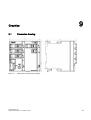
9.1
A
Accessories ................................................................................................................................. 51
Technical specifications ........................................................................................................................... 53
8.1
9
Approvals, Certificates ................................................................................................................ 45
Dimension drawing...................................................................................................................... 57
Appendix A .............................................................................................................................................. 59
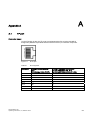
A.1
TP port......................................................................................................................................... 59
Glossary .................................................................................................................................................. 63
Index........................................................................................................................................................ 69
Tables
Table 2-1
Overview of the components supplied ........................................................................................ 14
Table 4-1
Pin assignment for the power supply .......................................................................................... 30
Table 4-2
Pin assignment of the signaling contact...................................................................................... 31
Table 7-1
Order numbers ............................................................................................................................ 51
Table 8-1
Ports ............................................................................................................................................ 53
Table 8-2
Electrical data.............................................................................................................................. 53
Table 8-3
Signaling contact......................................................................................................................... 54
Table 8-4
Permitted cable lengths (copper) ................................................................................................ 54
Table 8-5
Permitted cable lengths (fiber-optic) ........................................................................................... 54
Table 8-6
Aging time ................................................................................................................................... 54
Table 8-7
MTBF........................................................................................................................................... 55
Table 8-8
Permitted ambient conditions...................................................................................................... 55
Table A-1
Pin assignment............................................................................................................................ 59
4
SCALANCE X-300
Operating Instructions, 01, A5E01113043
1
Introduction
Purpose of the Operating Instructions
These Operating Instructions describe the functions of the compact Industrial Ethernet
Switches of the SCALANCE X-300 product line and support you during installation,
commissioning, and troubleshooting on site.
You will find information on configuring in the separate SCALANCE X-300 and
SCALANCE X-400 Configuration Manual.
"Operating Instructions (compact)" are also supplied with the product.
Validity of the Operating Instructions
These operating instructions are valid for the following products:
• Industrial Ethernet Switch SCALANCE X310
order number: 6GK5 310-0FA00-2AA3
• Industrial Ethernet Switch SCALANCE X308-2
order number: 6GK5 308-2FL00-2AA3
• Industrial Ethernet Switch SCALANCE X308-2 LD
order number: 6GK5 308-2FM00-2AA3
Names of the devices in these operating instructions
The descriptions in these operating instructions always apply to the compact Industrial
Ethernet Switches of the SCALANCE X-300 product line listed under "Validity of the
Operating Instructions" in this document unless the description relates to a specific device of
the product line. In the remainder of the description, the devices are called IE Switches X300.
Further documentation
For help on configuration and diagnostics using Web-based management, the CLI command
line, or SNMP, refer to the following documentation:
• SCALANCE X-300 SCALANCE X-400 Configuration Manual
C79000-G89xx-C187-06
(xx = German 00, English 76, French 77, Italian, 72 Spanish 78)
This configuration manual is available on the following media:
– On the supplied CD
– On the Internet at the address
http://support.automation.siemens.com/WW/view/xx/19625108
(xx = German 00, English 76, French 77, Italian 72, Spanish 78)
SCALANCE X-300
Operating Instructions, 01, A5E01113043
5
Introduction
• SIMATIC NET Twisted Pair and Fiber Optic Networks
This manual is available on the following media:
– In paper form under the order number C79000-G89xx-C125
(xx = German 00, English 76, French 77, Italian 72, Spanish 78)
– On the Internet at the address
http://support.automation.siemens.com/WW/view/xx/8763736
(xx = German de, English en, French fr, Italian it, Spanish es)
Standards, certificates and approvals
The devices of the SCALANCE X-300 product line meet the requirements for the CE mark.
For more detailed information, refer to the section "Approvals" in these Operating
Instructions.
6
SCALANCE X-300
Operating Instructions, 01, A5E01113043
Description
2.1
2
Basic information on Ethernet switching
Ethernet switching
Ethernet switches forward data packets directly from the input port to the appropriate output
port during data exchange based on the address information. Ethernet switches operate on a
direct delivery basis.
Essentially, switches have the following functions:
• Connection of collision domains / subnets
Since repeaters and star couplers (hubs) operate at the physical level, their use is
restricted to the span of a collision domain. Switches connect collision domains. Their use
is therefore not restricted to the maximum span of a repeater network. On the contrary,
extremely large networks with very large spans are possible with switches. The distances
achieved depend on the fiber-optic interfaces used in the devices and the FO fibers used
(see technical specifications).
• Containing load
By filtering the data traffic based on the Ethernet (MAC) addresses, local data traffic
remains local. In contrast to repeaters or hubs, which distribute data unfiltered to all ports
/ network nodes, switches operate selectively. Only data intended for nodes in other
subnets is switched from the input port to the appropriate output port of the switch. To
make this possible, a table assigning Ethernet (MAC) addresses to output ports is
created by the switch in a “teach-in" mode.
• Limiting errors to the affected subnet.
By checking the validity of a data packet on the basis of the checksum which each data
packet contains, the switch ensures that bad data packets are not transported further.
Collisions in one network segment are not passed on to other segments.
The need for Industrial Ethernet switches
With over 95% of LANs based on Ethernet, this is the most commonly used technology. The
use of switches is particularly important: They allow extensive networks with large numbers
of nodes to be set up, increase the data throughput, and simplify network expansion.
The IE Switches X-300 from SIMATIC NET are designed for use in high-speed plant
networks that will also meet future requirements. With the HSR redundancy function and
standby coupling of rings, high network availability can be achieved. Support of IT standards
such as VLAN, RSTP, IGMP, and GARP makes seamless integration of automation
networks in existing office networks possible.
The IE Switches X-300 are designed for use in switching cubicles and cabinets.
SCALANCE X-300
Operating Instructions, 01, A5E01113043
7
Description
2.1 Basic information on Ethernet switching
Technical options (network topologies)
The IE Switches X-300 simplify the expansion of a network regardless of the network
topology.
You can use an IE Switch X-300 in the following network topologies:
• Linear structure
• Star/tree structure
• Ring with redundancy manager
The maximum cable length is 10 km for single mode gigabit transmission. A mixed topology
between IE Switch X-300s and OSMs/ESMs is possible on the optical ports. Mixed operation
in the topology between SCALANCE X308-2 and an OSM over the optical ports is not
possible because the SCALANCE X308-2 only supports gigabit.
Using an IE Switch X-300 as the redundancy manager in a ring with redundancy manager
provides greater availability. If there is an interruption on the connection between these
switches, the IE Switch X-300 used as redundancy manager acts like a switch and in a very
short time creates a line from the ring with redundancy manager. As a result, a functional,
end-to-end structure is restored. For information on this topic, refer to the Configuration
Manual "SIMATIC NET; Industrial Ethernet Switches SCALANCE X-300 SCALANCE X-400."
2.1.1
Linear structure
Functional description
Linear structures can be created with the IE Switches X-300. The cascading depth and total
span of a network are limited only by the signal propagation times of the communication
connections.
Properties of the linear structure
Each IE Switch X-300 communicates over a TP or FO cable with a neighboring Ethernet
switch. Communication is possible over the optical or the electrical ports.
8
SCALANCE X-300
Operating Instructions, 01, A5E01113043
Description
2.1 Basic information on Ethernet switching
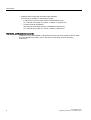
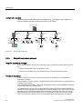
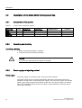
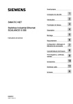
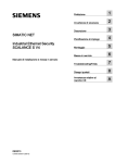
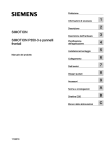
Configuration example
Sample configuration with SCALANCE X308-2, SIMATIC S7-300/400 and operator panel as
end devices.
0ELWV
)LEHU2SWLF
6&$/$1&(
;
6
6
6&$/$1&(
;
6
(76
6
(76
Figure 2-1
Linear structure (optical)
2.1.2
Star/tree structure
6&$/$1&(
;
6
6
(76
6&$/$1&(
;
(76
6
(76
Functional description
Star/tree structures can be created with the IE Switches X-300. The cascading depth and
total span of a network are limited only by the signal propagation times of the communication
connections.
Properties of a star structure
Each IE Switch X-300 communicates over a TP or FO cable with a central switch with which
all other switches are also connected within a star structure. Communication is possible over
the optical or the electrical ports.
SCALANCE X-300
Operating Instructions, 01, A5E01113043
9
Description
2.1 Basic information on Ethernet switching
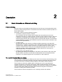
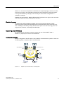
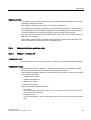
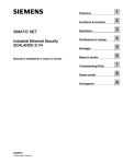
Configuration example
Sample electrical configurations with SCALANCE X310, SCALANCE X-200, SIMATIC S7300/400, SIMATIC ET 200, and operator panels as end devices.
SCALANCE X310
SCALANCE
X310
S7-400
SCALANCE
X208
SCALANCE
X208
S7-400
S7-300
S7-300
SCALANCE
X208
S7-300
ET 200S
ET 200S ET 200S ET 200S
ET 200S
Figure 2-2
Star structure (electrical)
2.1.3
Ring with redundancy manager
ET 200S
Ring with redundancy manager
To increase availability, linear (bus) topologies of up to 50 switches can be closed to form a
ring:
• Optical: SCALANCE X-400, SCALANCE X-300
• Electrical: SCALANCE X-400, SCALANCE X-300, SCALANCE X-200 or ESM
Functional description
The two ends of the bus are closed to form a ring by an IE Switch X-300 operating as a
redundancy manager.
The redundancy manager function is enabled by the SELECT/SET button or implemented by
a setting in the software.
For more detailed information, refer to the configuration manual "Industrial Ethernet Switches
SCALANCE X-300 SCALANCE X-400."
In contrast to the ring ports of the other IE Switches X-300, the ring ports of the redundancy
manager are disconnected when the network is operating problem-free. The IE Switch X-300
operating in the redundancy manager mode monitors the connected bus over its ring ports
and switches the ring ports through if there is an interruption on the connected bus; in other
words, it restores a functioning bus over this substitute path. Reconfiguration is achieved
10
SCALANCE X-300
Operating Instructions, 01, A5E01113043
Description
2.1 Basic information on Ethernet switching
within 0.3 s. As soon as the problem is eliminated, the original topology is restored; in other
words, the ring ports in the redundancy manager are disconnected from each other again.
In a ring with redundancy manager, there can only be one IE switch configured as a
redundancy manager.
(Defaults are ports 9 and 10. Both the RM and the IE switches in the ring must be connected
over these ring ports to allow redundancy to function.)
Electrical ring ports
An electrical ring with redundancy manager can be set up since the device provides
connectors (RJ-45 jacks) that allow attachment of electrical (twisted pair) connections (10,
100, 1000 Mbps). The factory setting defines the two ports no. 9 and 10 as ring ports. The
ring ports can, however, be reconfigured individually.
Optical ring ports (1000 Mbps)
An optical ring with redundancy manager requires the use of SCALANCE X308-2,
X308-2 LD. (Optical ports 9 and 10 are the defaults.
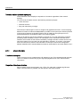
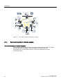
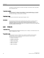
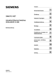
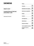
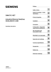
Configuration example
Sample configurations with IE Switch X-300, SIMATIC S7-200/300/400, operator control and
monitoring system, H system, and PC as end devices.
6&$/$1&(;
6&$/$1&(;
50
6
0ELWV
6
0ELWV
6&$/$1&(
;
6
+6\VWHP
Figure 2-3
+6\VWHP
Gigabit ring with redundancy manager (RM)
SCALANCE X-300
Operating Instructions, 01, A5E01113043
11
Description
2.1 Basic information on Ethernet switching
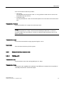
PC
S7-400
S7-400
Switch
SCALANCE
X308-2
PC
S7-300
)LEHU2SWLF
S7-400
Switch
SCALANCE
X308-2
0ELWV
S7-300
PC
PC
S7-300
PC
S7-400
S7-400
S7-400
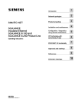
Figure 2-4
2.1.4
Ring with FO cable and redundancy manager
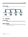
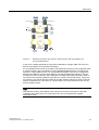
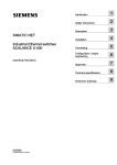
Redundant coupling of network segments
Redundant coupling of network segments
The example of the redundant linking of two network segments shown here, for example
rings with redundancy manager, can be implemented homogeneously with
SCALANCE X310 or SCALANCE X308-2 or mixed with SCALANCE X310 and
SCALANCE X308-2.
12
SCALANCE X-300
Operating Instructions, 01, A5E01113043
Description
2.1 Basic information on Ethernet switching
6&$/$1&(;
6&$/$1&(;
RM
S7-200
0ELWV
S7-300
10/100
Mbit/s
6&$/$1&(;
DVVWDQGE\PDVWHU
FRQILJXUHG
6&$/$1&(;
DVVWDQGE\VODYH
FRQILJXUHG
S7-400
6&$/$1&(
;
0ELWV
6&$/$1&(
;
RM
Figure 2-5
Redundant coupling of two subnets in mixed operation with SCALANCE X310
and SCALANCE X308-2
In this case, network segments are rings with a redundancy manager (RM). The rings can
also be interrupted at one point (linear topology).
For a redundant link as shown in the figure, two IE Switches X-300 must be configured within
a network segment. This configuration is set in Web Based Management, Command Line
Interface or using SNMP access. For more detailed information, refer to the "Configuration
Manual SCALANCE X-300 and SCALANCE X-400 Industrial Ethernet Switches". The two
IE Switches X-300 connected in the configuration exchange data frames with each other to
synchronize their operating statuses (one device is master and the other slave). If there are
no problems, only the link from the master to the other network segment is active. If this link
fails (for example due to a link-down or a device failure), the slave activates its link as long
as the problem persists.
Note
If IE Switches X-300 or SCALANCE X408-2 devices are used exclusively for redundant
coupling of the gigabit rings, the coupling links can also be designed with a gigabit
transmission rate.
SCALANCE X-300
Operating Instructions, 01, A5E01113043
13
Description
2.2 Description of the SCALANCE X-300 product line
2.2
Description of the SCALANCE X-300 product line
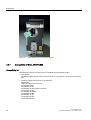
2.2.1
Components of the product
Table 2-1
Overview of the components supplied
Device type
SCALANCE
Device
2-pin plug-in
terminal block
4-pin plug-in
terminal block
Product information
Product CD
X310
+
+
+
+
+
X308-2
+
+
+
+
+
X308-2LD
+
+
+
+
+
2.2.2
Unpacking and checking
Unpacking, checking
1. Make sure that the package is complete.
2. Check all the parts for transport damage.
Warning
Do not use any parts that show evidence of damage!
2.2.3
Power supply and signaling contact
Power supply
The power supply is connected using a 4-pin plug-in terminal block.
The power supply can be connected redundantly. Both inputs are isolated. There is no
distribution of load. When a redundant power supply is used, the power supply unit with the
higher output voltage supplies the IE Switch X-300 alone. The power supply is connected
over a high resistance with the enclosure to allow an ungrounded set up. The two power
inputs are non-floating.
14
SCALANCE X-300
Operating Instructions, 01, A5E01113043
Description
2.2 Description of the SCALANCE X-300 product line
Signaling contact
The signaling contact (relay contact) is a floating switch with which error/fault states can be
signaled by breaking the contact.
The signaling contact is connected to a 2-pin plug-in terminal block.
The signaling by the signaling contact is synchronized with the fault LED, in other words, all
errors displayed by this LED (freely configurable) are also signaled on the signaling contact.
If an internal fault occurs, the fault LED lights up and the signaling contact opens.
The connection or disconnection of a communication node on an unmonitored port does not
lead to an error message.
The signaling contact remains activated until the error/fault is eliminated or until the current
status is entered in the fault mask as the new desired status.
2.2.4
Ethernet interfaces electrical ports
2.2.4.1
10Base-T / 100Base-TX
Transmission rate
The transmission rate of the electrical ports is 10 Mbps or as Fast Ethernet ports 100 Mbps.
Transmission mode
The transmission mode for 10Base-T / 100Base-TX is specified in the IEEE 802.3i / IEEE
802.3u standards of the Institute of Electrical and Electronic Engineers.
Autonegotiation (automatic detection of the best transmission modes) is default. The order in
which they are selected is:
• 100Base-TX full duplex
• 100Base-TX half duplex
• 10Base-T full duplex
• 10Base-T half duplex
Two communication modes are possible:
• Half duplex
Two-way alternate transmission mode - it is only possible to either send or receive over
the interfaces at any one time.
• Full duplex mode
Two-way simultaneous - both communication partners can send and receive at the same
time.
SCALANCE X-300
Operating Instructions, 01, A5E01113043
15
Description
2.2 Description of the SCALANCE X-300 product line
Connections to other switches can use half or full duplex; connections to hubs are possible
only in half duplex mode.
Transmission medium
Data transmission at 10 Mbps and at 100 Mbps is over two wire pairs (pin 1, 2, 3, 6) of the
twisted pair cable. For 10 Mbps, at least a category 3 (Cat 3) and for 100 Mbps, at least a
four-wire (2x2) category 5 (Cat 5) cable is necessary.
Transmission range
The maximum transmission range (segment length) is 100 m.
Connectors
The connectors used are 8-pin RJ-45 jacks with securing collars. The securing collar in
conjunction with the cover ensures a flush fit and the locking mechanism with the
PROFINET-compliant male connectors IE FC RJ-45 Plug 180 and IE FC RJ-45 Plug 145
provides a rugged node attachment suitable for an industrial environment that provides strain
and bending relief for the RJ-45 jack.
2.2.4.2
1000Base-TX
Transmission rate
The transmission rate of the electrical Ethernet ports is 10 Mbps, as Fast Ethernet ports 100
Mbps or as gigabit ports 1 Gbps.
Transmission mode
The transmission mode for 1000Base-TX is specified in the IEEE 802.3ab standard.
Autonegotiation (automatic detection of the best transmission modes) is default.
The order in which they are selected is:
• 1000Base-TX full duplex
• 1000Base-TX half duplex
• 100Base-TX full duplex
• 100Base-TX half duplex
• 10Base-T full duplex
• 10Base-T half duplex
16
SCALANCE X-300
Operating Instructions, 01, A5E01113043
Description
2.2 Description of the SCALANCE X-300 product line
Two communication modes are possible:
• Half duplex
Two-way alternate transmission mode - it is only possible to either send or receive over
the interfaces at any one time.
• Full duplex mode
Two-way simultaneous - both communication partners can send and receive at the same
time.
Transmission medium
Data is transmitted over an eight-wire twisted pair cable.
Notice
For data transmission at 1 Gbps, at least a Cat 5e twisted-pair cable with 4 x 2 wires is
necessary. With a four-wire cable (2 x 2 wires), a maximum data transmission rate of 100
Mbps is possible.
Transmission range
The maximum transmission range (segment length) is 100 m.
Connectors
The connectors used are 8-pin RJ-45 jacks.
2.2.5
Ethernet interfaces optical ports
2.2.5.1
1000Base-SX
Transmission rate
The transmission rate of the optical gigabit ports is 1 Gbps.
Transmission mode
Transmission with 1000Base-SX is defined in the IEEE 802.3z standard and is specified as
1000 Mbps transmission rate and full duplex.
SCALANCE X-300
Operating Instructions, 01, A5E01113043
17
Description
2.2 Description of the SCALANCE X-300 product line
Transmission medium
Data is transmitted over multimode FOC. The wavelength is 850 nm.
The core diameter of the multimode FOC is 50 µm; the light source is an LED. Many modes
(light beams) are used for signal transmission. The propagation times of the light pulses
(dispersion) restrict the maximum range considerably.
Transmission range
The maximum transmission range (segment length) is 750 m when using SIMATIC NET
fiber-optic multimode FOC with SC duplex connectors.
Connectors
SC duplex female connectors are used.
2.2.5.2
1000Base-LX
Transmission rate
The transmission rate of the optical gigabit ports is 1 Gbps.
Transmission mode
Transmission with 1000Base-LX is defined in the IEEE 802.3z standard and is specified as
1000 Mbps transmission rate and full duplex.
Transmission medium
Data is transmitted over single mode FOC. The wavelength is 1310 nm.
The core diameter of the single mode FOC is 9 or 10 µm; the light source is a laser diode. To
transmit a signal, only one mode (light beam) is used greatly reducing dispersion. As a
result, the maximum range of single mode FOC is greater than that of multimode FOC.
Transmission range
The maximum transmission distance (segment length) is 10 km for 1000Base-LX
transmission.
Connectors
SC duplex female connectors are used.
18
SCALANCE X-300
Operating Instructions, 01, A5E01113043
Description
2.2 Description of the SCALANCE X-300 product line
2.2.6
C-PLUG (configuration plug)
Area of application
The C-PLUG is an exchangeable medium for storage of the configuration data of the IE
Switch and ships with the product. This means that the configuration data remains available
if the IE Switch is replaced.
Notice
The C-PLUG must only be removed or inserted when the power supply to the device is
turned off.
How it works
Power is supplied by the IE Switch. The C-PLUG retains all data permanently when the
power is turned off.
If an empty C-PLUG (factory settings or deleted with the Clean function) is inserted, all the
configuration data of the IE Switch is saved to it automatically when the device starts up.
Changes to the configuration during operation without operator intervention are saved on the
C-PLUG if this is in the "ACCEPTED" status.
An IE Switch with an accepted C-PLUG inserted uses the configuration data of the C-PLUG
automatically when it starts up. Acceptance is possible only when the data was written by a
compatible device type.
This allows an IE Switch to be replaced quickly and simply. The C-PLUG is taken from the
failed component and inserted in the replacement. The first time it is started up, the
replacement device has the same configuration as the failed device except for the MAC
address set by the vendor.
Diagnostics
Inserting a C-PLUG that does not contain the configuration of a compatible device type,
accidentally removing the C-PLUG or general malfunctions of the C-PLUG are signaled by
the diagnostics mechanisms of the IE Switch (LEDs, WEB-based management, SNMP, CLI
and PROFINET diagnostics).
Inserting in the C-PLUG slot
The slot for the C-PLUG is located on the back of the device.
To insert the C-PLUG, remove the screw cover. The C-PLUG is inserted in the receptacle.
The screw cover must then be closed correctly.
Removing the C-PLUG
It is only necessary to remove the C-PLUG if the IE Switch develops a fault.
The C-PLUG can be removed from the slot using flat pliers, tweezers, or a small screwdriver.
SCALANCE X-300
Operating Instructions, 01, A5E01113043
19
Description
2.2 Description of the SCALANCE X-300 product line
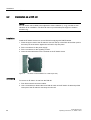
Figure 2-6
2.2.7
Removing the C-PLUG from the receptacle
Compatibility of SCALANCE X-300
Compatibility list
The following products and devices are compatible with IE Switches X-300:
• End devices
All SIMATIC NET products with a TP port can be connected to the ports of IE Switches X300.
• Network components in linear or star structure
ESM/OSM
OMC (TP cable max. 6 m long)
SCALANCE X005
SCALANCE X-100
SCALANCE X-100 medium converter
SCALANCE X-200
SCALANCE X-200IRT
SCALANCE X-300
SCALANCE X-400
SCALANCE S-600
SCALANCE W-700
20
SCALANCE X-300
Operating Instructions, 01, A5E01113043
Description
2.2 Description of the SCALANCE X-300 product line
• Network components in a ring structure with IE Switches X-300 a RM
– Ring structure electrical
(All IE Switches X-300 possible, it may be necessary to reconfigure ring ports):
ESM/OSM
SCALANCE X-200
SCALANCE X-200IRT
SCALANCE X-300
SCALANCE X-400
– Optical ring structure
(possible only with SCALANCE X308-2, X308-2LD):
SCALANCE X-400
SCALANCE X-300
• Redundant coupling of networks.
– In the network segment with the master-slave pair of devices to be configured:
SCALANCE X-400
SCALANCE X-300
on the standby link also to SCALANCE X-200
– In the network segment to be coupled:
ESM/OSM
SCALANCE X-200
SCALANCE X-200IRT
SCALANCE X-300
SCALANCE X-400
Note
All compatibility information assumes the correct use of the TP and FOC cables.
SCALANCE X-300
Operating Instructions, 01, A5E01113043
21
Description
2.3 Product variants
2.3
Product variants
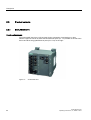
2.3.1
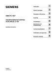
SCALANCE X310
Possible attachments
The SCALANCE X310 has 10 RJ-45 jacks for the connection of end devices or other
network segments. Seven of these are Fast Ethernet ports (P1 - P7) located on the left of the
device and three are gigabit Ethernet ports (P8 - P10) on the right.
Figure 2-7
22
SCALANCE X310
SCALANCE X-300
Operating Instructions, 01, A5E01113043
Description
2.3 Product variants
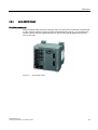
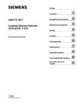
2.3.2
SCALANCE X308-2
Possible attachments
The SCALANCE X308-2 has 8 RJ-45 jacks and 2 FO ports for the connection of end devices
or other network segments. Seven of these are Fast Ethernet ports (P1 - P7) located on the
left of the device and one gigabit Ethernet port (P8) and two optical gigabit ports (P9 and
P10) on the right.
Figure 2-8
SCALANCE X308-2
SCALANCE X-300
Operating Instructions, 01, A5E01113043
23
Description
2.3 Product variants
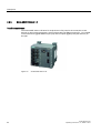
2.3.3
SCALANCE X308-2 LD
Possible attachments
The SCALANCE X308-2 LD has 8 RJ-45 jacks and 2 FO ports for the connection of end
devices or other network segments. Seven of these are Fast Ethernet ports (P1 - P7) located
on the left and one gigabit Ethernet port (P8) and two optical gigabit ports (P9 and P10) on
the right.
Figure 2-9
24
SCALANCE X308-2 LD
SCALANCE X-300
Operating Instructions, 01, A5E01113043
3
Installation
3.1
Installation
Types of installation
IE Switches X-300 can be installed in various ways:
• Installation on a 35 mm DIN rail
• Installation on a SIMATIC S7-300 standard rail
• Wall mounting
Note
When installing and operating the device, keep to the installation instructions and safetyrelated notices as described here and in the manual SIMATIC NET Industrial Ethernet
Twisted Pair and Fiber Optic Networks /1/.
Unless stated otherwise, the mounting options listed below apply to all IE Switch X-300.
Note
Provide suitable shade to protect the IE Switch X-300 against direct sunlight. This avoids
unnecessary warming of the IE Switches X-300 and prevents premature aging of the
IE Switch X-300 and cabling.
Warning
If temperatures in excess of 70 °C occur on cables or at cable feed-in points, or the
temperature at the branching point of the cables exceeds 80 °C, special measures need
to be taken. If the equipment is operated at an ambient temperature of 50 °C - 60 °C, use
cables with a permitted ambient temperature of at least 80 °C.
SCALANCE X-300
Operating Instructions, 01, A5E01113043
25
Installation
3.2 Installation on a DIN rail
3.2
Installation on a DIN rail
Caution
If the IE Switch -300 is liable to be subjected to severe vibration (> 10 g), use the S7-300
standard rail for installation. The DIN rail does not provide adequate support if vibration
exceeds 10 g.
Installation
Install the IE Switch X-300 on a 35 mm DIN rail complying with DIN EN 50022.
1. Place the upper catch of the IE Switch X-300 over the top of the DIN rail and then push in
the lower part of the device against the rail until it clips into place.
2. Fit the connectors for the power supply.
3. Fit the connectors for the signaling contact.
4. Insert the terminal blocks into the sockets on the IE Switch X-300.
Figure 3-1
IE Switch X-300 installation on a DIN rail (35 mm)
Uninstalling
To remove an IE Switch X-300 from the DIN rail:
1. First disconnect all connected cables.
2. Use a screwdriver to release the lower DIN rail catch of the IE Switch X-300 and pull the
lower part of the IE Switch X-300 away from the rail.
26
SCALANCE X-300
Operating Instructions, 01, A5E01113043
Installation
3.3 Installation on a standard rail
Figure 3-2
3.3
IE Switch X-300 removing from a DIN rail (35 mm)
Installation on a standard rail
Installation on a SIMATIC S7-300 standard rail
1. Place the upper guide at the top of the IE Switch X-300 housing in the S7 standard rail.
2. Screw the IE Switch X-300 to the underside of the standard rail.
3. Fit the connectors for the power supply.
4. Fit the connectors for the signaling contact.
5. Insert the terminal blocks into the sockets on the IE Switch X-300.
Figure 3-3
IE Switch X-300 installation on a SIMATIC S7-300 standard rail
Uninstalling
To remove an IE Switch X-300 from the SIMATIC S7-300 standard rail:
1. First disconnect all connected cables.
2. Loosen the screws on the underside of the S7 standard rail and lift the IE Switch X-300
away from the rail.
SCALANCE X-300
Operating Instructions, 01, A5E01113043
27
Installation
3.4 Wall mounting
3.4
Wall mounting
Wall mounting
1. For wall mounting, use suitable mounting fittings for the wall
(for example, for a concrete wall, four plugs 6 mm diameter and 30 mm long, 4 screws
3.5 mm diameter and 40 mm long).
2. Connect the electrical cable connecting cables.
3. Fit the connectors for the signaling contact.
4. Insert the terminal blocks into the sockets on the IE Switch X-300.
For more exact dimensions, please refer to the section "Dimension drawings".
Note
The wall mounting must be capable of supporting at least four times the weight of the
IE Switch X-300.
28
SCALANCE X-300
Operating Instructions, 01, A5E01113043
Connecting
4
Warning
Commissioning devices and replacement devices
If you use redundancy mechanisms (HSR ring redundancy and/or redundant coupling of
rings over standby), open the redundant path before you insert a new or replacement device
in an operating network. A bad configuration or attachment of the Ethernet cables to
incorrectly configured ports causes overload in the network and a breakdown in
communication.
A device may only be inserted in a network and connected when:
• HSR:
The ring ports of the device being inserted in the HSR ring were actually configured as
ring ports and "Ring redundancy enabled" was set. (Refer to the "Configuration manual
SCALANCE X-300 X-400, section X-300 Ring Configuration"). If the device is intended to
operate as the redundancy manager, "Redundancy manager enabled" must also be set.
(Refer to the "Configuration manual SCALANCE X-300 X-400, section X-300 Ring
Configuration").
• Standby coupling:
The standby connection must be "enabled" and the "Standby connection name" must
match the name of the partner device. You must also select the port in "Enable standby
port monitoring". (Refer to the "Configuration manual SCALANCE X-300 X-400, section
X-300 Standby Mask").
4.1
Power supply
Power supply
The power supply is connected using a 4-pin plug-in terminal block.
The power supply can be connected redundantly. Both inputs are isolated. There is no
distribution of load. When a redundant power supply is used, the power supply unit with the
higher output voltage supplies the IE Switch X-300 alone. The power supply is connected
over a high resistance with the enclosure to allow an ungrounded set up. The two power
inputs are non-floating.
SCALANCE X-300
Operating Instructions, 01, A5E01113043
29
Connecting
4.1 Power supply
Table 4-1
Pin assignment for the power supply
Pin number
Assignment
Pin 1
L1+ 24 V DC
Pin 2
M1
Pin 3
M2
Pin 4
L2+ 24 V DC
Warning
The IE Switch X-300 is designed for operation with safety extra-low voltage (SELV). This
means that only safety extra-low voltages (SELV) complying with IEC950/EN60950/
VDE0805 can be connected to the power supply terminals.
The power supply unit for the IE Switch X-300 power supply must meet NEC Class 2, as
described by the National Electrical Code(r) (ANSI/NFPA 70).
The power of all connected power supply units must total the equivalent of a power source
with limited power (LPS limited power source).
If the device is connected to a redundant power supply (two separate power supplies), both
must meet these requirements.
The signaling contact can be subjected to a maximum load of 100 mA (safety extra-low
voltage (SELV), 24 V DC).
Never operate the device with AC voltage or DC voltage higher than 32 V DC.
Caution
If IE Switches X-300 are supplied over long 24 V power supply lines or networks, measures
are necessary to prevent interference by strong electromagnetic pulses on the supply lines.
These can result, for example, due to lightning or switching of large inductive loads.
One of the tests used to attest the immunity of devices of the IE Switches X-300 to
electromagnetic interference was the "surge immunity test" according to EN61000-4-5. This
test requires overvoltage protection for the power supply lines. A suitable device is, for
example, the Dehn Blitzductor VT AD 24 V type no. 918 402 or comparable protective
element.
Manufacturer: DEHN+SÖHNE GmbH+Co.KG, Hans-Dehn-Str.1, Postfach 1640, D-92306
Neumarkt, Germany.
30
SCALANCE X-300
Operating Instructions, 01, A5E01113043
Connecting
4.2 Signaling contact
4.2
Signaling contact
Signaling contact
The signaling contact (relay contact) is a floating switch with which error/fault states can be
signaled by breaking the contact.
The signaling contact is connected to a 2-pin plug-in terminal block.
Table 4-2
Pin assignment of the signaling contact
IE Switch X-300
Pin number
Assignment
Pin 1
F1
Pin 2
F2
The signaling by the signaling contact is synchronized with the fault LED, in other words, all
errors displayed by this LED (freely configurable) are also signaled on the signaling contact.
If an internal fault occurs, the fault LED lights up and the signaling contact opens.
The connection or disconnection of a communication node on an unmonitored port does not
lead to an error message.
The signaling contact remains activated until the error/fault is eliminated or until the current
status is entered in the fault mask as the new desired status.
4.3
Grounding
Installation on a DIN rail
The device is grounded over the DIN rail.
S7 standard rail
The device is grounded over its rear panel and the neck of the screw.
SCALANCE X-300
Operating Instructions, 01, A5E01113043
31
Connecting
4.4 Fitting the IE FC RJ-45 Plug
Wall mounting
The device is grounded by the securing screw in the unpainted hole.
Please note that IE Switches X-300 must be grounded over one securing screw with
minimum resistance.
If an IE Switch X-300 is mounted on a non-conducting base, a grounding cable must be
installed. The grounding cable is not supplied with the device. Connect the paint-free surface
of the IE Switch X-300 to the nearest grounding point using the grounding cable.
4.4
Fitting the IE FC RJ-45 Plug
Assembly of the IE FC RJ-45 Plug on an IE FC Standard Cable
For information on assembling an IE FC RJ-45 Plug on a SIMATIC NET Industrial Ethernet
FastConnect cable, please refer to the instructions supplied with the IE FC RJ-45 Plug.
Inserting the IE FC RJ-45 Plug
1. Insert the IE FC RJ-45 Plug until it locks in place in the twisted pair port of the IE Switch
(on a 1000 Mbps gigabit Ethernet port, the RJ-45 plug can only be used for 100 Mbps).
Figure 4-1
Inserting the IE FC RJ-45 Plug (based on the example of the IE FC RJ-45 Plug 180)
The flush fit and locking mechanism of the PROFINET-compliant IE FC RJ-45 Plug along
with the securing collar on the TP port of the IE Switch guarantee a robust node connection
suitable for industrial conditions providing tensile and bending strain relief for the twisted pair
socket.
32
SCALANCE X-300
Operating Instructions, 01, A5E01113043
Connecting
4.4 Fitting the IE FC RJ-45 Plug
Removing the IE FC RJ-45 Plug
1. Press on the locking mechanism of the IE FC RJ-45 Plug gently to remove the plug.
Figure 4-2
Releasing the RJ-45 plug (based on the example of the IE FC RJ-45 Plug 180)
If there is not enough space to release the lock with your hand, you can also use a 2.5 mm
screwdriver. You can then remove the IE FC RJ-45 Plug from the twisted pair socket.
Figure 4-3
Releasing the RJ-45 plug with a screwdriver (based on the example of the IE FC RJ-45
Plug 180)
SCALANCE X-300
Operating Instructions, 01, A5E01113043
33
Planning/Configuring
5.1
Operator controls
5.1.1
SELECT / SET button
5
SELECT / SET button
The SELECT / SET button is used to switch over the display modes (DMode) and to make
other settings. After turning on the IE Switch X-300, it is in DMode A.
The button has the following functions:
• Changing the display modes
By pressing the button briefly, you change from one display mode to the next. The
selected mode or current status is displayed by the LED (DM).
• Resetting to the factory defaults
It is possible to restore the factory defaults in DMode A. by pressing the button for 12
seconds. You can cancel the reset procedure by releasing the button before the 12
seconds have elapsed. All previously made settings are overwritten by the factory
defaults.
• Defining the fault mask and the LED displays
It is possible to set the fault mask in DMode A and DMode D. This allows you to specify
the mask for signaling faults by defining an individual "good status“ for the connected
ports and the power supplies. In this case, you press the button for 5 seconds in DMode
A or DMode D. After 3 seconds, the LED (DM) begins to flash. You can cancel the
procedure by releasing the button before the 5 seconds have elapsed. If, however, you
press the button for a further 2 seconds, the current states of all ports and the states of
the power supplies L1 and L2 are included in the fault mask. The previous fault mask is
then overwritten.
• Activating/deactivating the redundancy manager
It is only possible to activate/deactivate the RM in DMode B. by pressing the button for 5
seconds. After 3 seconds, the LED (DM) begins to flash. If you release the button before
the 5 seconds have elapsed, the action is aborted. After 5 seconds the redundancy
manager is activated/deactivated. If the redundancy manager as well as ring redundancy
were deactivated, ring redundancy is also activated at the same time. If you deactivate,
only the redundancy manager is deactivated.
SCALANCE X-300
Operating Instructions, 01, A5E01113043
35
Planning/Configuring
5.2 LED display
5.2
LED display
5.2.1
LED display
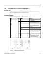
Overview
The following table shows the states indicated by the LEDs in the various display modes.
IE Switch X-300
5.2.2
LED
Display mode A Display mode B Display mode C Display mode D
F
Problem, signaling contact opens
L1
Power supply L1 is applied.
Power supply L1 is
monitored
L2
Power supply L2 is applied.
Power supply L2 is
monitored
RM
Device is operating as RM
SB
Device operates in standby mode.
DM
off
Lit green
Lit orange
Flashes
orange/yellow
P1
P2
P3
P4
P5
P6
P7
P8
P9
P10
Port status
Transmission
rate
Half / full
duplex
Fault mask
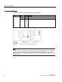
Startup behavior of the SCALANCE X-300
Startup behavior of the IE Switch X-300
While the device is starting up, the red LED "F" signals the current status of the
IE Switch X-300. You will find more detailed information in the following table:
36
LED on
LED off
LED flashing
During device startup
IE Switch X-300 starts
or there is a fault
Device startup
successful
Bad firmware image
During operation
Fault/error detected
Operation not OK
SCALANCE X-300
Operating Instructions, 01, A5E01113043
Planning/Configuring
5.2 LED display
Figure 5-1
5.2.3
Fault LED
Selecting the display modes
Selecting the display modes
Press the SELECT/SET button on the IE Switch X-300 until the DM LED lights up in the
required mode. The selected display mode is then activated.
There is an automatic switchover to Dmode A if the button is not pressed for longer than one
minute.
Figure 5-2
Displaying the four possible display modes
SCALANCE X-300
Operating Instructions, 01, A5E01113043
37
Planning/Configuring
5.2 LED display
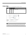
5.2.4
LED display - Fault and Power
Display modes A through C
In display modes A through C, the DM LED is lit as described in the section Selecting the
display modes. In these three states, the status of the signaling contact and the presence of
the supply voltages are displayed by the LEDs of the IE Switch X-300.
Figure 5-3
Example of the LED display of the device in DMode A
The following table lists the significance of the three LEDs on the IE Switch X-300 for display
modes A through C:
Label
Color
F
Red
L1
Green
L2
Green
38
Status
Meaning
off
The IE Switch X-300 has not detected any faults, the
signaling contact is closed.
on
The IE Switch X-300 has detected a fault, the signaling
contact opens.
off
Power supply L1 lower than 17 V.
on
Power supply L1 higher than 17 V.
off
Power supply L2 lower than 17 V.
on
Power supply L2 higher than 17 V.
SCALANCE X-300
Operating Instructions, 01, A5E01113043
Planning/Configuring
5.2 LED display
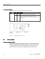
Display in display mode D
In display mode D, the DM LED of the IE Switch X-300 flashes yellow/orange. This mode
indicates whether the power supply is being monitored with the signaling contact.
Figure 5-4
LED Fault / Power and System display in display mode D
The following table shows the meaning of the three LEDs on the IE Switch X-300 in display
mode D:
Label
Color
F
Red
L1
Green
L2
Green
SCALANCE X-300
Operating Instructions, 01, A5E01113043
Status
Meaning
off
No problem has been detected by the IE Switch X-300.
on
The IE Switch X-300 detects a fault. The signaling contact
opens.
off
Power supply L1 is not monitored. If L1 falls below 17 V, the
signaling contact does not respond.
on
Power supply L1 is monitored. If L1 falls below 17 V, the
signaling contact responds.
off
Power supply L2 is not monitored. If L2 falls below 17 V, the
signaling contact does not respond.
on
Power supply L2 is monitored. If L2 falls below 17 V, the
signaling contact responds.
39
Planning/Configuring
5.2 LED display
5.2.5
LED display - System
System
On the IE Switch X-300, the LEDs of the system are on the right-hand LED strip.
Display modes A through D
The set display modes are indicated as follows:
50
50
50
50
6%
6%
6%
6%
'0
'0
'0
'0
'0/('OLWJUHHQ
'0/('OLWRUDQJH
'0/('IODVKHV
\HOORZRUDQJH
'0RGH%
'0RGH&
'0RGH'
'0RGH$
Figure 5-5
Display of the possible display modes (DMode A through DMode D)
The individual functions (RM, SB and DM) are independent of each other. The LED displays
are described below:
Label
Color
RM
Green
Status
Meaning
off
The IE Switch X-300 is not operating in redundancy
manager mode.
on
The IE Switch X-300 is operating in redundancy manager
mode. The ring is working without problems, monitoring is
activated.
flashes The IE Switch X-300 is operating in redundancy manager
mode. An interruption has been detected on the ring; the
IE Switch X-300 has switched through.
SB
Green
off
The standby function is disabled.
on
The standby function is enabled. The standby link is
passive.
flashes The standby function is enabled. The standby link is active.
DM
40
off
Mode A
Green
on
Mode B
Orange
on
Mode C
Yellow/orang
e
flashes Mode D
SCALANCE X-300
Operating Instructions, 01, A5E01113043
Planning/Configuring
5.2 LED display
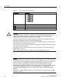
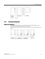
5.2.6
LED display of the ports (DMode A through DMode D)
LEDs of the ports
The LED displays of the 10 ports indicate different port states depending on the set display
mode. The displays have the same meaning for all ports.
Port statuses in DMode A
In display mode A, the current port status is displayed.
Port
Color
P1
P2
P3
P4
P5
P6
P7
P8
P9
P10
Green
Status
Meaning
off
No valid link to the port (for
example station turned off or cable
not connected)
on
Link exists and port in normal
status. In this status, the port can
receive and send data.
flashes once per period
Link exists and port in "blocking"
status. In this status, the port only
receives management data (no
user data).
flashes three times per
period
Link exists and port turned off by
management. In this status, no data
is sent or received over the port.
flashes four times per period Port exists and is in the "monitor
port" status. In this status, the data
traffic of another port is copied to
this port.
Yellow
Flashes / lit
Link exists, port is in normal status
and data is being received at the
port.
The optical gigabit ports of the
IE Switch X-300 signal data
reception and data transmission.
Figure 5-6
Display of the port status of port 1
SCALANCE X-300
Operating Instructions, 01, A5E01113043
41
Planning/Configuring
5.2 LED display
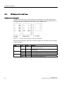
Port statuses in DMode B
In display mode B, the current transmission rate is displayed.
Port
P1
P2
P3
P4
P5
P6
P7
P8
P9
P10
Figure 5-7
Color
Status
Meaning
off
Port operating at 10 Mbps
Green
on
Port operating at 100 Mbps
Orange
on
Port operating at 1000 Mbps
Display of the transmission speed of port 1
Note
If there is a link fault and the type of transmission is fixed (autonegotiation off), in DMode B,
the desired status, in other words the set transmission rate (1000 Mbps, 100 Mbps, 10
Mbps) continues to be displayed. If there is a link fault and autonegotiation is active, the port
LED goes off.
42
SCALANCE X-300
Operating Instructions, 01, A5E01113043
Planning/Configuring
5.2 LED display
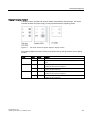
Port statuses in DMode C
In display mode C, the current mode (half duplex, full duplex) is indicated.
Port
Color
P1
P2
P3
P4
P5
P6
P7
P8
P9
P10
Figure 5-8
Green
Status
Meaning
off
Port operating in half duplex
on
Port operating in full duplex
Mode display (full / half duplex) of port 1
Note
If there is a link fault and the type of transmission is fixed (autonegotiation off), in DMode C,
the desired status, in other words the set type of transmission (full or half duplex) continues
to be displayed. If there is a link fault and autonegotiation is active, the port LED goes off.
SCALANCE X-300
Operating Instructions, 01, A5E01113043
43
Planning/Configuring
5.3 Show Location
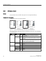
Port statuses in DMode D
In display mode D, you can see whether or not the port is monitored.
Port
Color
P1
P2
P3
P4
P5
P6
P7
P8
P9
P10
Figure 5-9
5.3
Green
Status
Meaning
off
The port is not monitored; in other words, if a link is not established
at the port, this does not trigger the signaling contact.
on
Port is monitored; in other words, if there is no link established at
the port (for example cable not plugged in or connected
IE Switch X-300 turned off), this triggers the signaling contact and
to a fault state.
Example: Monitoring of port 1 is "on“
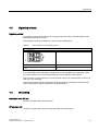
Show Location
Localizing an IE Switches X-300
To identify an IE Switch X-300 locally and with certainty, you can use the "show location"
function on a programming device to select the node over the network and make it flash.
This can be used, for example, when assigning addresses to make sure that the correct
node receives the address. All port LEDs of the addressed node flash green at 2 Hz.
With the PST Tool V3.0 or higher, you can trigger this function with "Module \ Flash".
44
SCALANCE X-300
Operating Instructions, 01, A5E01113043
6
Certifications and approvals
6.1
Approvals, Certificates
Note
The specified approvals apply only when the corresponding mark is printed on the product.
You can check which of the following approvals have been granted for your product by the
markings on the type plate.
Order number
IE Switch SCALANCE X310
6GK5 310-0FA00-2AA3
IE Switch SCALANCE X308-2
6GK5 308-2FL00-2AA3
IE Switch SCALANCE X308-2 LD
6GK5 308-2FM00-2AA3
CE mark
SIMATIC NET SCALANCE X-300 Industrial Ethernet switches meet the requirements and
aims of the following EU directives and comply with the harmonized European standards
(EN) for programmable logic controllers published in the Official Journal of the European
Communities:
• Directive 89/336/EEC "Electromagnetic Compatibility" (EMC Directive)
• Directive 73/23/EEC ”Electrical Equipment Designed for Use within Certain Voltage
Limits” (Low Voltage Equipment Directive)
• Directive 94/9/EEC Equipment and Protective Systems intended for Use in Potentially
Explosive Atmospheres (Explosion Protection Directive).
The EC Declarations of Conformity are available for the responsible authorities according to
the above-mentioned EC Directive at the following address:
Siemens Aktiengesellschaft
Bereich Automatisierungs- und Antriebstechnik
Industrielle Kommunikation SIMATIC NET
Postfach 4848
D-90327 Nürnberg, Germany
SCALANCE X-300
Operating Instructions, 01, A5E01113043
45
Certifications and approvals
6.1 Approvals, Certificates
EMC directive
The products are designed for use in an industrial environment:
Area of application
Requirements
Industrial area
Emission
Immunity
EN 61000-6-4 : 2001
EN 61000-6-2: 2001
Explosion protection directive
Complying with EN 60079-15 (electrical apparatus for potentially explosive atmospheres;
Type of protection “n”)
II 3 G EEx nA II T 4 KEMA 03 ATEX 1226X
Note
When using (installing) SIMATIC NET products in hazardous area zone 2, make absolutely
sure that the associated conditions are adhered to.
You will find these conditions on the SIMATIC NET Manual Collection.
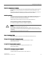
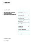
FDA and IEC approvals
The following device meets the FDA and IEC requirements listed below
• SCALANCE X308-2 LD
)'$
,(&
&RPSOLHVZLWK&)5
DQG
&/$66/$6(5352'8&7
Figure 6-1
FDA and IEC approvals
Machinery directive
The product remains a component in compliance with Article 4(2) of the EC Machinery
Directive 89/392/EEC.
According to the machinery directive, we are obliged to point out that the product described
is intended solely for installation in a machine.
Before the final product can be put into operation, it must be tested to ensure that it conforms
with the directive 89/392/EEC.
46
SCALANCE X-300
Operating Instructions, 01, A5E01113043
Certifications and approvals
6.1 Approvals, Certificates
Note for the manufacturers of machines
This product is not a machine in the sense of the EC Machinery Directive. There is therefore
no declaration of conformity relating to the EC Machinery Directive 89/392/EEC for this
product.
If the product is part of the equipment of a machine, it must be included in the procedure for
obtaining the declaration of conformity by the manufacturer of the machine.
Installation guidelines
The products meet the requirements if you adhere to the installation and safety instructions
contained in these Operating Instructions SIMATIC NET Industrial Ethernet Switches
SCALANCE X-300 and in the following documentation:
SIMATIC NET Industrial Twisted Pair and Fiber Optic Networks Manual /2/
This documentation is available on the Internet at the address
http://support.automation.siemens.com/WW/view/xx/8763736
(xx = German 00, English 76, French 77, Italian 72, Spanish 78)
Warning
Personal injury and damage to property may occur.
The installation of expansions that are not approved for SIMATIC NET products or their
target systems may violate the requirements and regulations for safety and electromagnetic
compatibility.
Only use expansions that are approved for the system.
Notice for Australia (C-TICK)
The product meets the requirements of the AS/NZS 2064 standard (Class A).
UL Approval for Information Technology Equipment
Underwriters Laboratories (UL) complying with Standard UL 60950-1
Report Number E115352
UL Approval for Industrial Control Equipment
Underwriters Laboratories (UL) complying with Standard UL 508
Report Number E85972
CSA Approval for Information Technology Equipment
CSA Certification Mark
Canadian Standard Association CSA C22.2 No. 60950-1-03
SCALANCE X-300
Operating Instructions, 01, A5E01113043
47
Certifications and approvals
6.1 Approvals, Certificates
CSA Approval for Industrial Control Equipment
CSA Certification Mark
Canadian Standard Association CSA C22.2 No. 14-M91
cULus Approval for Information Technology Equipment
cULus Listed 60E9 I. T. E.
Underwriters Laboratories Inc. complying with
• UL 60950-1 (Information Technology Equipment)
• CSA C22.2 No. 60950-1-03
cULus Approval for Industrial Control Equipment
cULus Listed 69B1
Underwriters Laboratories Inc. complying with
• UL 508
• CSA C22.2 No. 14-M91
cULus Approval Hazardous Location
cULus Listed 21BP I. T. E. FOR HAZ. LOC.
Underwriters Laboratories Inc. complying with
• UL 60950-1 (Information Technology Equipment)
• CSA C22.2 No. 60950-1-03
• UL 1604 and 2279-15 (Hazardous Location)
Approved for use in
Cl. 1, Div. 2, GP. A, B, C, D, T4
Cl. 1, Zone 2, GP. IIC T4
Cl. 1, Zone 2, Aex nC IIC T4
48
SCALANCE X-300
Operating Instructions, 01, A5E01113043
Certifications and approvals
6.1 Approvals, Certificates
FM Approval
The product meets the requirements of the standards
• Factory Mutual Approval Standard Class Number 3611
• FM Hazardous (Classified) Location Electrical Equipment:
Non Incendive / Class I / Division 2 / Groups A,B,C,D / T4 and
Non Incendive / Class I / Zone 2 / Group IIC / T4
Note
When used in environments corresponding to Class I, Division 2 or Class I, Zone 2 (see
above), the product must be installed in a cabinet, a suitable enclosure, or closed room.
Warning
In hazardous areas, personal injury or damage to property may occur if you make or
break an electrical circuit while an IE Switch X-300 is in operation.
Do not connect or disconnect equipment when a flammable or combustible atmosphere is
present.
ATEX Approval
The product meets the requirements of the standard
• EN60079-15
Warning
When used under hazardous conditions (zone 2), IE Switches X-300 must be installed in
an enclosure.
To comply with ATEX95 (EN 60079-15), this enclosure must meet the requirements of at
least IP54 in compliance with EN 60529.
WARNING - EXPLOSION HAZARD: DO NOT DISCONNECT EQUIPMENT WHEN A
FLAMMABLE OR COMBUSTIBLE ATMOSPHERE IS PRESENT.
If temperatures in excess of 70 °C occur on cables or at cable feed-in points, or the
temperature at the branching point of the cables exceeds 80 °C, special measures need
to be taken. If the equipment is operated at an ambient temperature of 50 °C - 60 °C, use
cables with a permitted ambient temperature of at least 80 °C.
Protective measures must be taken to avoid the rated voltage of the equipment being
exceeded by more than 40% by transient overvoltages. This is the case if the equipment
is supplied exclusively by SELV circuits.
SCALANCE X-300
Operating Instructions, 01, A5E01113043
49
Certifications and approvals
6.1 Approvals, Certificates
Certification
The products and systems listed in this document are manufactured and marketed using a
quality management system complying with DIN ISO 9001 and certified by DQS (certificate
registration no. 2613). The DQS certificate is recognized in all IQNet countries (Reg. no.
2613).
Devices connected to the system must meet the relevant safety regulations.
The EC Declaration of Conformity is available for the responsible authorities according to the
above-mentioned EC Directive at the following address:
Siemens Aktiengesellschaft
Bereich Automatisierungs- und Antriebstechnik
Industrielle Kommunikation SIMATIC NET
Postfach 4848
D-90327 Nürnberg, Germany
This declaration certifies compliance with the directives named above, but does not
guarantee any specific properties.
50
SCALANCE X-300
Operating Instructions, 01, A5E01113043
7
Accessories
7.1
Accessories
Table 7-1
Order numbers
Order number
Available for SCALANCE
6GK1970-1BA10-0AA0
All
IE FC Stripping Tool
6GK1901-1GA00
All
IE FC blade cassettes
6GK1901-1GB00
All
IE FC TP standard cable GP
6XV1840-2AH10
All
IE FC TP trailing cable
6XV1840-3AH10
All
"Industrial Ethernet TP and Fiber Optic Networks"
manual
IE FC TP marine cable
6XV1840-4AH10
All
IE FC TP trailing cable GP
6XV1870-2D
All
IE FC TP flexible cable GP
6XV1870-2B
All
IE TP torsion cable
6XV1870-2F
All
IE FC RJ-45 Plug 180 pack of 1
6GK1901-1BB10-2AA0
All
IE FC RJ-45 Plug 180 pack of 10
6GK1901-1BB10-2AB0
All
IE FC RJ-45 Plug 180 pack of 50
6GK1901-1BB10-2AE0
All
C-PLUG
6GK1900-0AB00
SCALANCE X-200/X-300/X-400/W-700
IE SC RJ PCF Plug
6GK1900-0NB00-0AC0
IE SC RJ POF Plug
6GK1900-0MB00-0AC0
IE termination kit SC RJ PCF Plug
6GK1900-0NL00-0AA0
IE termination kit SC RJ POF Plug
6GK1900-0ML00-0AA0
SCALANCE X-300
Operating Instructions, 01, A5E01113043
51
8
Technical specifications
8.1
Technical specifications
Device type
Dimensions (W x H x D) in mm
Weight in g
Installation options
SCALANCE
- DIN rail
- S7-300 standard rail
- Wall mounting
X310
120 x 125 x 123
1400
+
X308-2
120 x 125 x 123
1400
+
X308-2 LD
120 x 125 x 123
1400
+
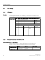
Table 8-1
Ports
Device type
SCALANCE
Attachment of end devices or network components
over twisted pair
X310
7 x RJ-45 sockets with MDI-X pinning 10/100 Mbps
(half/ full duplex)
Connecting end devices or
network components over
fiber-optic
Connector for
power supply
Connector for
signaling contact
1x4-pin plug-in
terminal block
1x2-pin plug-in
terminal block
2 SC duplex sockets
(1000 Mbps, full duplex to
1000BaseSX)
1 x 4-pin plug-in
terminal block
1 x 2-pin plug-in
terminal block
2 SC duplex sockets
(1000 Mbps, full duplex to
1000BaseLX)
1 x 4-pin plug-in
terminal block
1 x 2-pin plug-in
terminal block
-
3 x RJ-45 sockets with MDI-X pinning
10/100/1000 Mbps (half/ full duplex)
X308-2
7 x RJ-45 sockets with MDI-X pinning 10/100 Mbps
(half/ full duplex)
1 x RJ-45 socket with MDI-X pinning
10/100/1000 Mbps (half/ full duplex)
X308-2 LD
7 x RJ-45 sockets with MDI-X pinning 10/100 Mbps
(half/ full duplex)
1 x RJ-45 socket with MDI-X pinning
10/100/1000 Mbps (half/ full duplex)
Table 8-2
Device type
SCALANCE
Electrical data
Power supply
2 x 24 V DC
Power loss at
24 V DC
Current consumption
at rated voltage
(18-32 V DC)
Safety extra-low voltage
(SELV)
Overcurrent protection at
input
Non-replaceable fuse
(F 3 A / 32 V)
X310
+
9.6 W
400 mA
+
X308-2
+
9.6 W
400 mA
+
X308-2 LD
+
9.6 W
400 mA
+
SCALANCE X-300
Operating Instructions, 01, A5E01113043
53
Technical specifications
8.1 Technical specifications
Table 8-3
Signaling contact
Device type
SCALANCE
Voltage at signaling contact
X310
24 V DC
max. 100 mA
X308-2
24 V DC
max. 100 mA
X308-2 LD
24 V DC
max. 100 mA
Table 8-4
Device type
SCALANCE
Current through signaling contact
Permitted cable lengths (copper)
0 - 55 m
IE TP torsion cable with IE
FC RJ-45 Plug 180 or
0 - 85 m
IE FC TP marine/trailing/ flexible cable
with IE FC RJ-45 Plug 180
0 - 100 m
IE FC TP standard cable with IE FC RJ-45
plug 180
0 - 45 m IE TP torsion
cable with IE outlet RJ-45
+ 10 m TP cord
or
or
0 - 75 m IE FC TP marine/ trailing/flexible
cable + 10 m TP cord over IE FC outlet
RJ-45
over IE FC outlet RJ-45 with 0 - 90 m IE FC
TP standard cable + 10 m TP cord
X310
+
+
+
X308-2
+
+
+
X308-2 LD
+
+
+
Table 8-5
Device type
SCALANCE
Permitted cable lengths (fiber-optic)
0 - 750 m
glass FOC
0 - 10000 m
glass FOC
0 - 40000 m
glass FOC
0 - 70000 m
glass FOC
50/125 µm multimode
fiber;
2.5 dB/km at 850 nm
9/125 µm single mode fiber;
0.5 dB/km at 1310 nm;
9/125 µm single mode fiber;
0.4 dB/km at 1310 nm;
9/125 µm single mode fiber;
0.28 dB/km at 1550 nm;
6 dB max. permitted FO
cable attenuation with 3 dB
link power margin
18 dB max. permitted FO
cable attenuation with 2 dB
link power margin
21 dB max. permitted FO
cable attenuation with 2 dB
link power margin
4.5 dB max. permitted FO
cable attenuation with
3 dB link power margin
X310
-
-
-
-
X308-2
+
-
-
-
X308-2 LD
-
+
-
-
Note
Maximum insertion loss of 0.5 dB per SC connector.
Table 8-6
Device type
SCALANCE
Aging time
Aging time
X310
30 seconds
X308-2
30 seconds
X308-2 LD
30 seconds
54
SCALANCE X-300
Operating Instructions, 01, A5E01113043
Technical specifications
8.1 Technical specifications
Table 8-7
MTBF
Device type
SCALANCE
MTBF
X310
46 years
X308-2
48 years
X308-2 LD
48 years
Table 8-8
Permitted ambient conditions
Device type
SCALANCE
Operating temperature
Storage/transport
temperature
Relative humidity in
operation
Operating altitude at max. xx°C
ambient temperature
X310
0 °C through +60 °C
-40 °C through +70 °C
‹ 95 %
(no condensation)
2000 m at max. 56 °C
3000 m at max. 50 °C
X308-2
0 °C through +60 °C
-40 °C through +70 °C
‹ 95 %
(no condensation)
2000 m at max. 56 °C
3000 m at max. 50 °C
X308-2 LD
0 °C through +60 °C
-40 °C through +70 °C
‹ 95 %
(no condensation)
2000 m at max. 56 °C
3000 m at max. 50 °C
Note
The following applies to IE Switches X-300
The number of IE Switches X-300 connected in a line influences the frame propagation time.
When a frame passes through an IE Switch X-300, it is delayed by the Store&Forward
function of the IE Switch X-300
• with a 64 byte frame length by approx. 10 microseconds (at 100 Mbps)
• with a 1500 byte frame length by approx. 130 microseconds (at 100 Mbps)
This means that the more IE Switch X-300 devices the frame passes through, the longer the
frame delay.
SCALANCE X-300
Operating Instructions, 01, A5E01113043
55
Graphics
9.1
Dimension drawing
Figure 9-1
SCALANCE X310 dimension drawings
SCALANCE X-300
Operating Instructions, 01, A5E01113043
9
57
Graphics
9.1 Dimension drawing
Figure 9-2
SCALANCE X308-2 dimension drawings
Figure 9-3
58
Drilling template for the IE Switch X-300
SCALANCE X-300
Operating Instructions, 01, A5E01113043
A
Appendix A
A.1
TP port
Connector pinout
On the IE Switch X-300, the TP ports are implemented as RJ-45 jacks with MDI-X
assignment (Medium Dependent Interface–Autocrossover) of a network component.
Figure A-1
RJ-45 jack
Table A-1
Pin assignment
Pin number
Pinning of the Fast Ethernet
ports
all IE-Switches X-300 (P1-P7)
Pinning of the gigabit Ethernet ports
on SCALANCE X310 (P8 - P10)
on SCALANCE X308-2, X308-2LD (P8)
Pin 8
n. c.
3-
Pin 7
n. c.
3+
Pin 6
TD-
1-
Pin 5
n. c.
2-
Pin 4
n. c.
2+
Pin 3
TD+
1+
Pin 2
RD-
0-
Pin 1
RD+
0+
SCALANCE X-300
Operating Instructions, 01, A5E01113043
59
Appendix A
A.1 TP port
Notice
TP cords or TP-XP cords with a maximum length of 10 m can be connected to the RJ-45 TP
port.
With the IE FC cables and IE FC RJ-45 plug, an overall cable length of up to 100 m is
permitted between two devices depending on the cable type.
Autonegotiation
Autonegotiation means the automatic detection of the functionality of the port at the opposite
end. Using autonegotiation, network components or end devices can detect the functionality
available at the port of a partner device allowing automatic configuration of different types of
device. With autonegotiation, two components connected to a link segment can exchange
parameters and set themselves to match the supported communication functionality.
Note
With devices that do not support autonegotiation, the IE Switch X-300 port must be set
manually to the speed and duplexity settings of the device (in other words, the identical
setting).
Note
The IE Switch X-300 is a plug-and-play device that does not require settings to be made for
commissioning.
60
SCALANCE X-300
Operating Instructions, 01, A5E01113043
Appendix A
A.1 TP port
MDI /MDIX autocrossover function
The advantage of the MDI /MDIX autocrossover function is that straight-through cables can
be used throughout and crossover Ethernet cables are unnecessary. This prevents
malfunctions resulting from mismatching send and receive wires. This makes installation
much easier for the user.
The IE Switches X-300 all support the MDI / MDIX autocrossover function.
Note
Autocrossover works only in autonegotiation is enabled. If the setting is fixed, there is no
autocrossover (see Glossary).
Notice
Please note that a direct connection between two ports on the IE Switch X-300 or an
accidental connection over several IE Switches X-300 can cause illegal formation of loops
unless RSTP or STP is activated. Such a loop can lead to network overload and network
failures.
SCALANCE X-300
Operating Instructions, 01, A5E01113043
61
Glossary
Aging time
The aging time is the time after which a learned MAC address is discarded if an IE Switch X300 has not received frames with this sender address during this time.
Autocrossover
Technique with which a TP port is automatically switched over between MDI and MDIX
assignment to make a connection independent of the port assignment of the device being
attached. This means that crossover cables are not required. The autocrossover function
can only be used when the port is set to autonegotiation mode.
Autonegotiation
Procedure standardized by IEEE 802.3 in which the transmission parameters (for example
10/100 Mbps, full/half duplex) are negotiated automatically between the devices.
BOOTP
A protocol for automatic assignment of IP addresses. The IP addresses are provided by a
BOOTP server.
CLI
Command Line Interpreter. Terminal-based configuration option for the IE Switch X-300.
With TELNET, the CLI can be used over every Ethernet port.
Collision domain
To ensure that the CSMA/CD protocol functions correctly, the propagation time of a data
packet from one node to another is restricted. This propagation time results in a spatially
limited span for the network depending on the data rate known as the collision domain.
Connection monitoring
With regular link test pulses, IE Switch X-300 monitors the connected TP and FO cable
segments for short-circuits or interruptions. The IE Switch X-300 does not send data to a
segment from which it is not receiving link test pulses.
SCALANCE X-300
Operating Instructions, 01, A5E01113043
63
Glossary
C-PLUG
The C-PLUG (configuration plug) is an exchangeable memory medium of storing the
configuration data. If the device is replaced, the configuration can be adopted by swapping
the C-PLUG.
CRC
Cyclic Redundancy Check. A checksum used in transmission protocols to detect errors in
frames.
Cut Through
With this technique, a frame is forwarded as soon as the destination address is recognized.
The delay is therefore not dependent on the frame length.
Default gateway
A network node that forwards all frames not addressed to stations in the same LAN (subnet).
DHCP
DHCP (Dynamic Host Configuration Protocol), like BOOTP, a method for automatic
assignment of IP addresses. With DHCP, however, addresses can be assigned while the
device is operating.
Dispersion
Broadening and distortion of light pulses in fiber-optic cable due to signals arriving at
different times. On multimode FOC, the distortion of the output signal is greater than with
single mode FOC.
Display mode (DMode)
Display mode that indicates various statuses (port status, power monitoring activated etc.).
The modes can be switched over using a button on the IE Switch X-300.
ESM
Electrical Switching Module – SIMATIC NET Ethernet switch with electrical ports.
Event
For Alarms & Events: An event is anything that happens that could be of interest to a client.
Although events can also be generated when a condition is met, they are not necessarily
dependent on conditions. Events that are not linked to conditions include, for example, error
messages of the communication system.
64
SCALANCE X-300
Operating Instructions, 01, A5E01113043
Glossary
Fault mask
Specifies the desired status (good status). Deviations from this occurring during operation
are handled as faults.
FO port
Fiber Optic port
Full duplex
Two-way simultaneous - both communication partners can send and receive at the same
time.
Half duplex
Two-way alternate transmission mode- it is only possible to either send or receive over the
interfaces at any one time.
Latency
Latency specifies the time taken by frames to pass through an IE Switch X-300. This does
not include the time required for buffering frames.
Load containment
With its filtering functions, a switch makes sure that local data traffic remains local. The local
network load of a segment is contained in the originating segment and does not represent
extra load on the remainder of the network.
MDI
Medium Dependent Interface, - straight.
On a MDI port or a MDI cable, the receive (Rx) and
transmit (Tx) cables are not crossed over.
MDI-X
Medium Dependent Interface – crossover.
On an MDI-X port or MDI-X cable, the receive (Rx) and
the send (Tx) lines are crossed over.
MIB
Management Information Base. The MIB is a formal description of network objects in the
form of a tree structure that contains all the relevant information for network management in
SNMP.
SCALANCE X-300
Operating Instructions, 01, A5E01113043
65
Glossary
Mirroring
A port (mirror port) with its specific data traffic can be mirrored to another port (monitor port)
for test purposes. Protocol analysis devices can be connected to the monitor port, in other
words, the monitor port is not available for data exchange. Mirroring has no effect on the
mirror port.
Modes
Modes are discrete waves used to transmit data within a fiber-optic cable. With single mode
fibers, only one wave propagates, whereas in multimode fibers several waves propagate.
Modes are patterns of electromagnetic fields in FOCs.
Multicast
A frame with a multicast address is received by all nodes prepared to receive this address.
Multimode
In multimode transmission, the pulse is transferred using many modes (waves) that travel
along curved paths or are reflected within the core. Attenuation is mainly caused by physical
absorption and dispersion as well as by mechanical bending. The amount of attenuation
depends among other things on the wavelength of the input light. Multimode fiber-optic
cables have an outer diameter of 125 µm and 50 or 62.5 µm core diameter. Due to the larger
core diameter the pulse edges degrade more than in single mode transmission resulting in
shorter transmission distances.
OSM
Optical Switching Module – SIMATIC NET Ethernet switch with optical ports.
Passive listening
Support of Rapid Spanning Tree Topology Change frames. When an RSTP topology change
frame is received, the MAC address table is deleted.
PCF
Polymer Cladded Fiber
Optical fiber that can be assembled in the field and whose core is made of glass and jacket
made of plastic.
POF
Plastic Optical Fiber
Optical fiber that can be assembled in the field and whose core and jacket are made of
plastic.
66
SCALANCE X-300
Operating Instructions, 01, A5E01113043
Glossary
Rapid Spanning Tree
The Rapid Spanning Tree protocol (RSTP) allows redundant transmission paths. This
prevents circulating frames and, if a fault develops, provides an alternative path within
seconds (reconfiguration time).
Reconfiguration time
The time required to restore a functional configuration if a device fails or a network cable is
interrupted.
Redundancy manager (RM)
IE Switch X-300 in a ring topology that does not forward any frames between its ring ports if
there are functioning connections between all other switches. As soon as a connection
between two switches is interrupted, the redundancy manager forwards frames between its
ring ports and so restores an intact connection between all switches.
Ring port
Two ports on an IE Switch X-300 via which it is connected to other switches to form a ring.
One IE Switch X-300 must be configured as the redundancy manager in the ring. This sends
test frames via the ring ports that are forwarded by all the ring ports of the other switches in
the ring. This makes sure that the ring does not have any interruptions.
RMON
Remote Monitoring. RMON-compliant devices allow diagnostic data to be collected on the
device and read out by a network management station. This means that network problems
are detected early and can be eliminated. The particular advantage of RMON is that it is
independent of location. The acquired data can be analyzed at any point in the network with
suitable reporting software.
Segment
In the Ethernet bus system, transceivers connected together over the bus cable along with
the nodes connected over patch cables form a segment. Several such segments can be
connected via repeaters. When using twisted pair and fiber-optic cables, each subsection
forms a segment.
Signaling contact
Floating relay contact via which the detected error states can be signaled.
Single mode
In single mode transmission, (and monomode transmission) the pulse is transmitted by a
straight mode (wave). Attenuation is mainly caused by physical absorption and dispersion as
well as by mechanical bending. The amount of attenuation depends, among other things, on
the wavelength of the input light. The single mode fiber typically has a core diameter of 5 to 9
µm. The outer diameter is, however, once again 125 µm (compare multimode). The smaller
SCALANCE X-300
Operating Instructions, 01, A5E01113043
67
Glossary
core diameter degrades the pulse edges less than multimode transmission and allows
greater transmission distances.
SNMP
Simple Network Management Protocol. Standardized protocol for transporting network
management information.
Spanning Tree
The Spanning Tree protocol (STP) allows redundant transmission paths. This prevents
circulating frames and, if a fault develops, provides an alternative path within 20 - 30
seconds (reconfiguration time).
Store and forward
In this switching technique, the entire frame is read in, before it is forwarded by the
IE Switch X-300. A packet is only passed on if it is error-free.
TELNET
With this protocol, an interactive connection can be established to another device in the LAN
or on the Internet. The user then has the same options as when directly connected to this
device with a terminal.
TFTP
Trivial File Transfer Protocol. A simple, UDP-based protocol for data transfer. Due to its
limited size, it can also be used by network nodes with little ROM.
TP port
Port with a TP connector (RJ-45 jack)
VLAN
Virtual LAN within a physically existing network.
WBM
Web Based Management. With WBM, configuration and diagnostics are handled with an
Internet browser. Entries made by the user are sent to the IE Switch X-300 using the HTTP
protocol and the IE Switch X-300 transfers its replies by HTTP to the user.
68
SCALANCE X-300
Operating Instructions, 01, A5E01113043
Index
A
ATEX95, 49
Autonegotiation, 15, 62
C
Communication modes, 15
Compatibility list, 21
Connector pinout
IE Switch X-300, 61
C-PLUG, 18
E
Ethernet switches, 7
L
LED display
System, 39
LED display - Power, 38
M
MDI /MDIX autocrossover function, 62
N
Network topologies, 8
Linear structure, 8
Redundant coupling of two network segments, 12
SCALANCE X-300
Operating Instructions, 01, A5E01113043
Ring with redundancy manager, 11
Star structure, 9
Node localization, 44
P
Port status
DMode A, 40
DMode B, 41
DMode C, 42
DMode D, 43
Possible attachments
SCALANCE 308-2 LD, 23
SCALANCEX310, 22, 23
R
Redundancy manager, 10
S
SELECT / SET button, 35
Selecting the display modes, 37
Startup behavior, 36
T
Transmission mode, 15
Full duplex, 15
Half duplex, 15
Transmission rate, 15
69