1
Owner's Manual/Manual
Del Propietario
112 HP
315MN= GARAGE DOOR OPENER
ABRIDOR
DE PUERTA DE COCHERA
For Residential
Model/Modelo
Use Only/Solo
DE 315MN=
para uso residencial
• 139.53648D
I11
Z
G3
m
m
Z_
O
Read and follow all safety rules
and operating instructions before
first use of this product.
Leer y seguir todas las reglas de
seguridad y las instrucciones de
operacion antes de usar este
producto por primera vez.
Fasten the manual near the garage
door after installation.
Guardar este manual cerca de la
puerta de la cochera.
Periodic checks of the opener are
required to ensure safe operation.
Se deben realizar revisiones
peribdicas del abridor de puertas
para asegurar su operacion
segura.
Sears, Roebuck
and Co., Hoffman
www.sears.com/craftsman
Estates,
IL 60179
U.S.A
TABLE
OF CONTENTS
Introduction
2.5
Adjustment
27.29
Safety symbol and signal word review ........................ 2
Adjust the travel limits ...............................................
27
Preparing your garage door ........................................
Tools needed ...............................................................
Adjust the force .........................................................
28
Planning ..................................................................
3
3
4-5
Test the safety reversal system ................................. 29
Test the Protector System ®........................................
Carton inventory ..........................................................
6
Operation
Hardware inventory .....................................................
7
Operation safety instructions .....................................
Assembly
8.11
29
30.34
30
Using your garage door opener ................................ 30
Assemble the rail and attach the pulley bracket ......... 8
Using the wall-mounted
Install the trolley ..........................................................
Attach the rail to the motor unit ...................................
To open the door manually ........................................
9
9
door control ........................ 31
31
Care of your garage door opener .............................. 32
Install the chain/cable and the sprocket cover .......... 10
Having a problem? ....................................................
33
Tighten the chain and cable ......................................
Diagnostic chart .........................................................
34
Installation
11
11-26
Programming
35.36
Installation safety instructions .................................... 11
Determine the header bracket location ..................... 12
To add or reprogram a hand-held remote control .....35
To erase all codes .....................................................
35
Install the header bracket ..........................................
3-function remotes .....................................................
13
35
Attach the rail to the header bracket ......................... 14
To add, reprogram or change a Keyless Entry PIN ..36
Position the opener ...................................................
15
Repair
Hang the opener .......................................................
Install the door control ...............................................
16
17
Rail assembly parts ...................................................
37
Installation parts ........................................................
37
Install the light ...........................................................
18
Motor unit assembly parts .........................................
38
Attach the emergency release rope and handle ....... 18
Electrical requirements ..............................................
19
Install the Protector System ®................................ 20-22
Fasten the door bracket ....................................... 23-24
Connect the door arm to the trolley ..................... 25-26
Parts
37.38
Accessories
39
Warranty
39
Repair
Parts
and Service
Back
Cover
INTRODUCTION
Safety
Symbol
and Signal
Word
Review
This garage door opener has been designed and tested to offer safe service provided it is installed, operated,
maintained and tested in strict accordance with the instructions and warnings contained in this manual.
Mechanical
When you see these Safety Symbols and Signal
Words on the following pages, they will alert you to
the possibility of serious injury or death if you do
not comply with the warnings that accompany them.
The hazard may come from something mechanical
or from electric shock. Read the warnings carefully.
Electrical
When you see this Signal Word on the following
pages, it will alert you to the possibility of damage to
your garage door and/or the garage door opener if
you do not comply with the cautionary statements
that accompany it. Read them carefully.
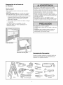
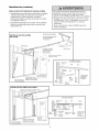
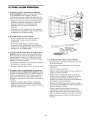
Preparing
your
garage
door
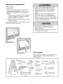
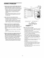
Before you begin:
• Disable locks.
To prevent possible SERIOUSINJURYOR DEATH:
• ALWAYScall a trained door systems technician if
garage door binds, sticks, or is out of balance An
unbalancedgarage door may not reverse when
required
• NEVERtry to loosen, move or adjust garage door,
door springs, cables, pulleys, brackets or their
hardware, all of which are under EXTREMEtension
• Disable ALL locks and remove ALL ropes connected to
garage door BEFOREinstalling and operating garage
door opener to avoid entanglement
• Remove any ropes connected to garage door.
• Complete the following test to make sure your
garage door is balanced and is not sticking or
binding:
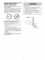
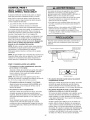
1. Lift the door about halfway as shown. Release
the door. If balanced, it should stay in place,
supported entirely by its springs.
2. Raise and lower the door to see if there is any
binding or sticking.
If your door binds, sticks, or is out of balance, call a
trained door systems technician.
To prevent damageto garage door and opener:
• ALWAYSdisable locks BEFOREinstalling and
operating the opener.
• ONLYoperate garage door opener at 120V, 60 Hz to
avoid malfunction and damage.
Sectional Door
Tools
One-Piece Door
needed
During assembly, installation and adjustment of the
opener, instructions will call for hand tools as
illustrated below.
Pencil
Level(optional)
Hack Saw
Tape Measure
Wire Cutters
Drill
3/16',
5/16"
and 5/32"
Stepladder
Screwdriver
and 1/4"
Adjustable
End Wrench
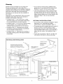
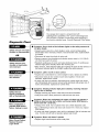
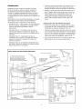
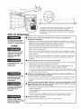
Planning
Identify the type and height of your garage door.
Survey your garage area to see if any of the
conditions below apply to your installation. Additional
materials may be required. You may find it helpful to
refer back to this page and the accompanying
illustrations as you proceed with the installation of
your opener.
Do you have an access door in addition to the
garage door? If not, Model 53702 Outside Quick
Release is required. See Accessories page.
Look at the garage door where it meets the floor.
Any gap between the floor and the bottom of the
door must not exceed 1/4" (6 mm). Otherwise, the
safety reversal system may not work properly. See
Adjustment Step 3. Floor or door should be
repaired.
Depending on your requirements, there are several
installation steps which may call for materials or
hardware not included in the carton.
• Installation Step 1 - Look at the wall or ceiling
above the garage door. The header bracket must
be securely fastened to structural supports.
SECTIONAL
• Installation Step 5 - Do you have a finished ceiling
in your garage? If so, a support bracket and
additional fastening hardware may be required.
• Installation Step 10- Depending upon garage
construction, extension brackets or wood blocks
may be needed to install sensors.
• Installation Step 10 -Alternate floor mounting of
the safety reversing sensor will require hardware
not provided.
DOOR INSTALLATIONS
• Do you have a steel, aluminum, fiberglass or glass
panel door? If so, horizontal and vertical
reinforcement is required (Installation Step 11).
• The opener should be installed above the center of
the door. If there is a torsion spring or center
bearing plate in the way of the header bracket, it
may be installed within 4 feet (1.2 m) to the left or
right of the door center. See Installation Steps 1
and 11.
• If your door is more than 7 feet (2.1 m) high, see
rail extension kits listed on Accessories page.
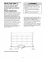
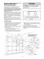
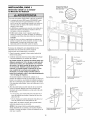
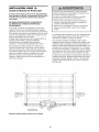
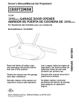
SECTIONAL DOOR INSTALLATION
FINISHED CEILING
Horizontal and vertical reinforcement
is needed for lightweight garage doors
(fiberglass, steel, aluminum, door with
glass panels, etc.). See page 23 for details.
Support bracket &
fastening hardware
is required.
See page 16.
Slack in chain tension
is normal when
garage door is closed.
Header Wall
\
Motor unit
Extension Spring
OR
Torsion Spring
Wallmounted
Door
Control
Vertical
I :........!
Centerline
Header
of Garage
Door
Bracket
CLOSED
Trolley,
//
o
K////J
_,_F_
V///A
POSITION
.......
Garage
/ /
DoorO
//
- .......
Chain
Sprin
_
Reversing Sensor
Gap between floor
and bottom of door
must not exceed 1/4" (6 ram).
Safety Reversing
Sensor
I-"cJ
Spring/i
V///_
S
/_7/
/_._
traight
Door
Emergency
Release
Arrn
Rope&Handle
d_
Header
Wall
_
[_
_]
Garage_
Door
_
I
I
I
'\
Door
Bracket
Curved
Door
Arm
_
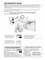
Planning
(Continued)
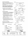
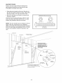
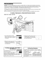
ONE-PIECE
DOOR INSTALLATIONS
• Generally, a one-piece door does not require
reinforcement. If your door is lightweight, refer to
the information relating to sectional doors in
Installation Step 11.
• Depending on your door's construction, you may
need additional mounting hardware for the door
bracket (Step 11).
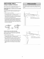
ONE-PIECE
Without a properly working safety reversal system,
persons (particularly small children) could be
SERIOUSLYINJUREDor KILLED by a closing garage
door.
• The gap between the bottom of the garage door and
the floor MUST NOT exceed 1/4" (6 mm). Otherwise,
the safety reversal system may not work properly.
• The floor or the garage door MUST be repaired to
eliminate the gap.
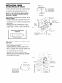
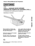
FINISHED CEILING
DOOR WITHOUT TRACK
Support bracket
& fastening
hardware is required.
See page 16.
Motor Unit
Slack in chain tension
is normal when
garage door is closed,
Header
Wall
Door
Control
Access
Door
CLOSED
POSITION
Cable
Pulley Bracket
O
Cable
o
Door
Jl
Safet
Reversing Sensor
Gap between floor and bottom of
Safety
door must not exceed 1/4" (6 ram)
Reversing Sensor
Trolley
i
.
Straight
Door _
__F_
_F_
arage ...........
Door
ONE-PIECE
Em,ergency
Release
BH_
,
o.,
Hope & Manale
Curved
Door
_ _
DOOR WITHOUT TRACK
Slack in chain tension is normal when
garage door is closed.
CLOSED
Cable
Pulley Bracket
Header
vea_ld
er _
Garage
Door
Safety
Reversing Sensor
Gap between floor
and bottom of door
must not
exceed 1/4" (6 turn)
Safety
Reversing
Sensor
Bracket
_//_
POSITION
Cable
Curved
Trolley
I
Siraig
Door
-
Arm
I
_
o,_)DoorArmc, o j /
oor
Bracket
Chain
Rail
I
Emergency Release
Rope & Handle
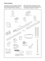
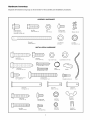
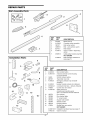
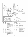
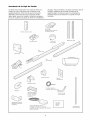
Carton
Inventory
Your garage door opener is packaged in two cartons
which contain the motor unit and all parts illustrated
below. Accessories will depend on the model
purchased. If anything is missing, carefully check the
packing material. Parts may be stuck in the foam.
Hardware for assembly and installation is shown on
the next page. Save the carton and packing material
until installation and adjustment is complete.
SECURITY+"
3-Function Remote Control
with Visor Clip(2)
Door Control Button
Door Bracket Plate
Cable
Door Bracket
Pulley Bracket
vv,_
Rail
J_
_J
Hanging Brackets
Motor Unit with Light Lens
Sprocket Cover
Header Bracket
2-Conductor Bell Wire
White & White/Red
"C" Wrap (2)
Safety Reversing Sensor
Mounting Bracket
With Slot (2)
Safety Reversing Sensor
Mounting Bracket
With Square Holes (2)
Curved Door
Arm Section
Safety Labels
and
Literature
(2) Safety Reversing Sensors
(1 Sending Eye and 1 Receiving Eye)
with 2-Conductor White & White/Black
Bell Wire attached
Straight Door
Arm Section
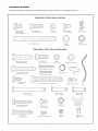
Hardware
Inventory
Separate all hardware and group as shown below for the assembly and installation procedures.
ASSEMBLY HARDWARE
i
Washered Bolt
5/16"-18xl/2"
(2)
(mounted in motor unit)
Hex Bolt
5/16"-18x7/8"
Nut
5/16"-18 (5)
(3)
Carriage Bolts
1/4"-20xl/2" (4)
Threaded
Trolley Shaft(l)
INSTALLATION
Lag Screw
Master Link (2)
©
©
Lock Washer
Lock Nut
5/16" (4)
1/4"-20x7/16"
HARDWARE
Hex Bolt
5/16"-9xl-5/8"
(2)
5/16"-18x7/8"
(4)
Nut 5/16"-18 (6)
Lock Washer
5/16" (6)
0
5/16"-18xl-7/8"
_ading
Ring
Fastener (3)
(2)
Handle
Screw
1/4"-14x5/8"
Carriage Bolt
5/16"-18x2-1/2"
(2)
(2)
Drywall Anchors (2)
Rope
o]
Clevis Pin
5/16"x2-3/4"
Clevis Pin
5/16"x1-1/4"
(1)
(1)
Clevis Pin
5/16"x1" (1)
©
1/4 x1-1/2"
(4)
Carriage Bolts
1/4"-20xl/2"
(4)
Lock Nut
1/4"-20 (4)
Wing Nut
1/4x20 (2)
@
Hex Bolt
1/4-20x1-1/2"
(2)
Screw
#10-32x3/8"
(4)
Lock Nut
#10x32 (4)
Insulated
Staples (30)
(4)
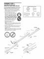
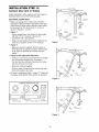
ASSEMBLY
STEP
1
Assemble
the Rail and
Attach
the Cable Pulley
Bracket
HARDWARE
SHOWN ACTUAL
SIZE
©
To avoid installation difficulties, do not run the
garage door opener until instructed to do so.
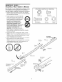
1. Align the three rail sections on a flat surface
exactly as shown. Front and back sections are
interchangeable for ease of assembly.
Lock Nut
1/4" - 20 x 7/16"
2. Insert the carriage bolts so the
square bolt necks seat in the square
holes in the rail sections and pass
through the round holes in the center
section rail. Make sure bolt necks
are seated in the square holes and
rails are aligned before you tighten
lock nuts. Improper assembly can
cause jerky trolley operation, noise
and/or nuisance door reversals.
Carriage Bolts
1/4" - 20 x 1/2"
Hex Screw
5/16"- 18 x 7/8"
Nut
5/16"- 18
Lock Washer
5/16"
3. Assemble lock nuts, ensure
alignment and tighten.
NOTE: If rail is not assembled exactly as shown,
trolley will not travel smoothly along length of rail
or it will hit against nuts.
4. Position the cable pulley bracket on the front end
of the rail as shown. Fasten securely with the
hardware shown.
RAIL RACK
(TO OPENER)
NOTE: When tightening the bolts, be sure to keep
bracket parallel to the rail. Otherwise, the rail may
bow when the opener is operated.
Rail
1/4" Lock Nut
(End
,@
Brace
Rail
(Center Section)
Brace
Hex Bolts
5/16'-18x7/8'
Rail
(End Section)
%
Cable Pulley
Bracket
Cable pufley bracket
attaches to FRONT
END of Rail
Square Carriage
Bolt Holes
RAIL FRONT
(TODOOR)
Section)
,\
\
\
\
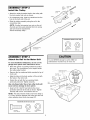
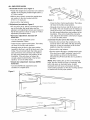
ASSEMBLY
Install
the
STEP
2
Trolley
Inner Nut
Washer
5/16"
5/16"f
i _"'.
Outer Nut
5/16"
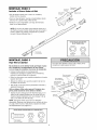
• Attach the trolley threaded shaft to the trolley with
the lock washer and nuts as shown.
• As a temporary stop, insert a screwdriver into the
hole in the front end of the rail.
Lock
Trolley
Threaded
Shaft
Trolley \
• Slide the trolley assembly along the rail to the
screwdriver stop.
NOTE: If trolley hits against any nuts on the rail,
the bolts and nuts were attached from the wrong
side and must be repositioned.
Review Assembly Step 1.
HARDWARE
Temporary
ASSEMBLY
Attach
the
STEP
Rail
Lock Washer
5/16"
Nut
5/16"- 18
3
to the
Motor
Unit
To avoid SERIOUSdamageto opener, ONLYuse
bolts/fasteners mounted in top of motor unit.
• Place the opener on packing material to protect
the cover. For convenience, put a support under
the cable pulley bracket.
Washered Screw
5/16"-18xl/2"
• Remove the two washered bolts mounted in top of
motor unit.
• Align the holes in the back section of the rail with
the holes in the motor unit.
• Fasten the rail with the two washered bolts
previously removed. Tighten securely.
Use only these bolts! Use of any other bolts will
cause serious damage to door opener.
• Insert a 5/16"-18x7/8" hex bolt into the cover
protection bolt hole in the rail as shown. Tighten
securely with a 5/16" lock washer and nut.
NOTE: This bolt prevents trolley over-traveL Keep a
2" (5 mm) minimum between the trolley and this bolt
when adjusting travel limits (see page 27).
SHOWN ACTUAL
SIZE
©©
Hex Bolt
Nut
Lock Washer
5/16"-18x7/8"
5/16"-18
5/16"
SIZE
©
Stop
To avoid installation difficulties, do not run the
garage door opener until instructed to do so.
HARDWARE
SHOWN ACTUAL
Hex Bolt
5/16"-18x7/8'
Cover
Protection
Bolt Hole \
Rail
(Back Section
5/16"
Nut
5/16"-18
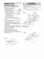
ASSEMBLY
Install
the
and Attach
STEP
4
Chain/Cable
the Sprocket
To avoid possible SERIOUSINJURYto fingers from
moving garage door opener:
• ALWAYSkeep hand clear of sprocket while operating
opener.
• Securely attach sprocket cover BEFOREoperating.
Cover
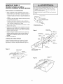
INSTALLING THE CHAIN/CABLE
1. Pull the cable loop from the
carton and fasten it to the
trolley with a master link from
the hardware bag (Figure 1). ""X
Leave Chain &
Cable Inside
Dispensing
Carton to
Prevent Kinking
Master Link
Figure 1
• Push pins of master link bar
j
through cable loop and hole KeepChainandCable
in front end of trolley.
Taut When Dispensing
Clip-On Sp[ing
Master Link
Clip-On Spring
• Push master link cap over
pins and past pin notches.
\
Threaded
Shaft
Rail
Cable
Loop
. Pin Notch
2. With the trolley against the screwdriver, dispense
the cable around the pulley.
Pin
3. Continue along the rail and around the motor unit
sprocket (Figure 2). The sprocket teeth must
engage the chain. Continue forward to the trolley
threaded shaft.
_'- Trolley
_'_
Master
Link Bar
Pulley
4. Use the second master link to connect the chain to
the flat end of the shaft (Figure 1). Check to make
sure the chain is not twisted.
INSTALL CHAIN & CABLE
IN THIS DIRECTION
5. Remove the screwdriver.
ATTACHING THE SPROCKET COVER
Insert the back tab in the slot on the back of the
mounting plate. Squeeze the cover slightly and insert
the front tab (Figure 3).
Figure 3
I
, ,
Master _-._
Link Cap
_h-
• Slide clip-on spring over cap and onto pin
notches until both pins are securely locked in
place.
Flat end
of Trolley
Master_
Link Cap
Figure 2
Sprocket
Cover
Back Tab Slot
Front Tab Slot
Mounting
Plate
10
Motor Unit
Sprocket
ASSEMBLY
Tighten
the
STEP
Chain
5
and
Cable
Outer Nut
Lock
Washer
Inner Nut
//
To Tight
• Spin the inner nut and lock washer down the
threaded shaft, away from the trolley.
• To tighten the chain, turn outer nut in the direction
shown. As you turn the nut, keep the chain
from twisting,
_
J
Q
|_
• When the chain is approximately 1/2" (13 mm)
above the base of the rail at its midpoint, re-tighten
the inner nut to secure the adjustment.
/
Inner Nut
Chain
Sprocket noise can result if chain is either too
loose or too tight.
When installation
chain droop with
the chain returns
door is open, do
1/2" (13 mm)
is complete, you may notice some
the door closed. This is normal. If
to the position shown when the
not re-adjust the chain.
Base of Rail
NOTE: During future maintenance, ALWAYS pull the
emergency release handle to disconnect trolley
before adjusting chain.
You have now finished assembling your garage
door opener. Please read the following warnings
before proceeding to the installation section.
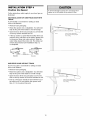
INSTALLATION
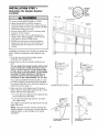
IMPORTANT INSTALLATION INSTRUCTIONS
To reduce the risk of SEVERE INJURY or DEATH:
1. READAND FOLLOWALL INSTALLATIONWARNINGS
AND INSTRUCTIONS.
8. NEVERwear watches, rings or loose clothing while
installing or servicing opener.They could be caught in
garage door or opener mechanisms.
2. Install garage door opener only on properly balanced
and lubricated garage door. An improperly balanced
door may not reverse when required and could result in
SEVEREINJURYor DEATH.
9. Install wall-mounted garage door control:
• within sight of the garage door
• out of reach of children at minimum height of 5 feet
(1.5m)
3. All repairs to cables, spring assemblies and other
hardware MUST be made by a trained door systems
technician BEFOREinstalling opener.
4. Disable all locks and remove all ropes connectedto
garage door BEFOREinstalling opener to avoid
entanglement.
5. Install garage door opener 7 feet (2.1 m) or more
above floor.
• away from all moving parts of the door.
10. Placeentrapment warning label on wall next to garage
door control.
11. Place manual release/safety reverse test label in plain
view on inside of garage door.
12. Upon completion of installation, test safety reversal
system. Door MUST reverse on contact with a
1-1/2" (3.8 cm) high object (or a 2x4 laid flat) on the
floor.
6. Mount emergency releasehandle 6 feet (1.8 m) above
floor.
7. NEVERconnect garage door opener to power source
until instructed to do so.
11
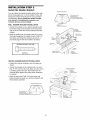
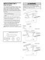
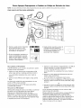
INSTALLATION
Determine
Location
the
STEP
Header
1
OPTIONAL
CEILING
MOUNT
FOR
HEADER
BRACKET
Bracket
Un[iini;h_
2x_
Header Wall
Vertical Centerline
of Garage Door
To prevent possible SERIOUSINJURYor DEATH:
• Header bracket MUST be RIGIDLYfastenedto
structural support on header wall or ceiling, otherwise
garage door might not reverse when required DO NOT
install header bracket over drywall
• Concrete anchors MUST be used if mounting header
bracket or 2x4 into masonry
• NEVERtry to loosen, move or adjust garage door,
springs, cables, pulleys, brackets, or their hardware,
all of which are under EXTREMEtension
2x4
Structural
/
Supports
• ALWAYScall a trained door systems technician if
garage door binds, sticks, or is out of balance. An
unbalancedgarage door might not reverse when
required.
Installation procedures vary according to garage door
types. Follow the instructions which apply to your
door.
F
1, Close the door and mark the inside vertical
centerline of the garage door,
2. Extend the line onto the header wall above the
door,
t_,
You can fasten the header bracket within 4 feet
(1.22 m) of the left or right of the door center
only if a torsion spring or center bearing plate
is in the way; or you can attach it to the ceiling
(see page 13) when clearance is minimal. (It
may be mounted on the wall upside down if
necessary, to gain approximately 1/2" (13 mm).
i
2" (5 cm)Track
Track
,_" Wall
(5 crn)
Header
Header Wall
of Travel
_nt
Door
V
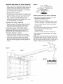
If you need to install the header bracket on a 2x4
(on wall or ceiling), use lag screws (not provided)
to securely fasten the 2x4 to structural supports as
shown here and on page 13,
Sectional
door with curved track
One-piece door with horizontal
track
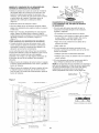
3, Open your door to the highest point of travel as
shown, Draw an intersecting horizontal line on the
header wall above the high point:
• 2" (5 cm) above the high point for sectional door
and one-piece door with track,
Header Wall
• 8" (20 cm) above the high point for one-piece
door without track.
crn)
_Wall
This height will provide travel clearance for the top
edge of the door,
NOTE: If the total number of inches exceeds the
height available in your garage, use the maximum
height possible, or refer to page 13 for ceiling
installation,
Door
_I_
Highest
Point
of Travel
Hightst
/O t
One-piece door without track:
jamb hardware
12
One=piece door without track:
pivot hardware
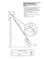
INSTALLATION
Install
the
STEP
Header
2
Bracket
Wall Mounting
You can attach the header bracket either
above the garage door, or to the ceiling.
instructions which will work best for your
requirements. Do not install the header
over drywall. If installing into masonry,
concrete anchors (not provided).
The nail hole is for
positioning only.
You must use lag screws
to mount the header bracke
WALL HEADER BRACKET INSTALLATION
Optional
Wall Mounting
• Center the bracket on the vertical centerline with
the bottom edge of the bracket on the horizontal
line as shown (with the arrow pointing toward the
ceiling).
SHOWN
Holes
Vertical
Centerline
of Garage Door
• Mark the vertical set of bracket holes (do not use
the holes designated for ceiling mount). Drill 3/16"
pilot holes and fasten the bracket securely to a
structural support with the hardware provided.
HARDWARE
Holes
to the wall
Follow the
particular
bracket
use
Header
Wall
-
Lag Screws
5/16"-9xl -5/8"
2x4
Structural
Support
i
Horizontal
Line
--_-- /
ACTUAL SIZE
/
t"
/
I EI I I I I
_" I
--
Highest Point of
Garage Door Travel
Lag Screw
5/16"-9xl
/
Garage
Door --
Vertical
Centerline
of Garage Door
-5/8"
CEILING HEADER BRACKET INSTALLATION
• Extend the vertical centerline onto the ceiling as
shown.
• Center the bracket on the vertical mark, no more
than 6" (15 cm) from the wall. Make sure the arrow
is pointing toward the wall. The bracket can be
mounted flush against the ceiling when clearance
is minimal.
• Mark the side holes. Drill 3/16" pilot holes and
fasten bracket securely to a structural support with
the hardware provided.
6" (15 cm)
Door
Lag Screws
5/16"-9xl -5/8"
Ceiling Mounting
Holes
Header Wall
The nail hole is for
positioning only.
You must use lag screws
to mount the header bracket,
of Garage Door
13
INSTALLATION
Attach
Bracket
Rail
to the
3
Header
• Position the opener on the garage floor below the
header bracket. Use packing material as a
protective base. NOTE: If the door spring is in the
way you'll need help. Have someone hold the
opener securely on a temporary support to allow
the rail to clear the spring.
Header Wall
zj
the
STEP
/ Header
Bracket
• Position the rail bracket against the header
bracket.
-- Cable
Pulley
Bracket
• Align the bracket holes and join with a clevis pin
as shown.
• Insert a ring fastener to secure.
Ring Fastener
Header
Bracket
0
i
\
"_
..I
Clevis Pin
5/16"x2-3/4"
Pulley
Bracket
Rail
Garage
Door
°o
Opener carton or
_
HARDWARE
SHOWN
ACTUAL SIZE
°1
Clevis Pin
5/16"x2-3/4"
Temporary
0
Ring Fastener
14
Support
INSTALLATION
Position
the
STEP
4
Opener
To prevent damageto garage door, rest garage door
opener rail on 2x4 placed on top section of door.
Follow instructions which apply to your door type as
illustrated.
SECTIONAL
TRACK
DOOR OR ONE-PIECE DOOR WITH
A 2x4 laid flat is convenient for setting an ideal
door-to-rail distance.
• Remove foam packaging.
• Raise the opener onto a stepladder. You will need
help at this point if the ladder is not tall enough.
• Open the door all the way and place a 2x4 laid flat
on the top section beneath the rail.
• If the top section or panel hits the trolley when you
raise the door, pull down on the trolley release arm
to disconnect inner and outer sections. Slide the
outer trolley toward the motor unit. The trolley can
remain disconnected until Installation Step 12
is completed.
_
__ Tr°llleYse
Arm-ENGAGED
RELEASED
ONE-PIECE DOOR WITHOUT TRACK
A 2x4 on its side is convenient for setting an ideal
door-to-rail distance.
• Remove foam packaging.
• Raise the opener onto a stepladder. You will need
help at this point if the ladder is not tall enough.
• Open the door all the way and place a 2x4 on its
side on the top section of the door beneath the rail.
2x4 is used to determine
the correct mounting height
from ceiling.
• The top of the door should be level with the top of
the motor unit. Do not position the opener more
than 4" (10 cm) above this point.
15
INSTALLATION
Hang
the
STEP
5
Opener
Three representative installations are shown. Yours
may be different. Hanging brackets should be angled
(Figure 1) to provide rigid support. On finished
ceilings (Figure 2 and Figure 3), attach a sturdy
metal bracket to structural supports before installing
the opener. This bracket and fastening hardware are
not provided.
1. Measure the distance from each side of the motor
unit to the structural support.
To avoid possible SERIOUSINJURYfrom a failing
garage door opener,fasten it SECURELYto structural
supports of the garage. Concrete anchors MUST be used
if installing any brackets into masonry.
Figure 1
Structural
,' Supports
2. Cut both pieces of the hanging bracket to required
lengths.
Lag Screws
5/16"-18xl -7/8"
3. Drill 3/16" pilot holes in the structural supports.
Measure",
Distance
4. Attach one end of each bracket to a support with
5/16"-18xl -7/8" lag screws.
5. Fasten the opener to the hanging brackets with
5/16"-18x7/8" hex bolts, lock washers and nuts.
6. Check to make sure the rail is centered over the
door (or in line with the header bracket if the
bracket is not centered above the door).
i
Bolt 5/16"-18x7/8"
Lock Washer 5/16"
Nut 5/16"-18
7. Remove the 2x4. Operate the door manually. If the
door hits the rail, raise the header bracket.
NOTE: DO NOT connect power to opener at this time.
HARDWARE
SHOWN ACTUAL
SIZE
_
_ _'%_J_
Bolt 5/16"-18x7/8"
Lock Washer 5/16"
Nut 5/16"-18
Lag Screw 5/16"-9xl
Hex Bolt
5/16"-18x7/8"
-5/8"
Nut 5/16"-18
Lock Washer
5/16'
Bolt 5/18"-18x7/8"
Lock Washer 5/16"
Nut 5/16"-18
16
.(Not
_ " _
Lock
Nut
Provided)
Washer
5/16"-18
5/16"
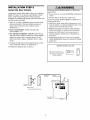
INSTALLATION
Install
the
Door
STEP
6
Control
To prevent possible SERIOUSINJURYor DEATHfrom
electrocution:
Locate door control within sight of door, at a minimum
height of 5 feet (1.5 m) where small children cannot
reach, away from moving parts of door and door
hardware. If installing into drywall, drill 5/32" holes and
use the anchors provided.
• Be sure power is not connected BEFOREinstalling door
control.
• Connect ONLYto 24 VOLTlow voltage wires.
To prevent possible SERIOUSINJURYor DEATHfrom a
closing garage door:
• Install door control within sight of garage door, out of
reach of children at a minimum height of 5 feet (1.5 m),
and away from all moving parts of door.
• NEVERpermit children to operate or play with door
control push buttons or remote control transmitters.
• Activate door ONLYwhen it can be seen clearly, is
properly adjusted, and there are no obstructions to
door travel.
1. Strip 1/4" (6 mm) of insulation from one end of bell
wire and connect to the two terminal screws on
back of door control by color: white to 2 and
white/red to 1.
2. Door Control Button:
screws 6ABx1-1/2".
Fasten securely with
3. (For standard installation only) Run bell wire up
wall and across ceiling to motor unit. Use insulated
staples to secure wire in several places. Do not
pierce wire with a staple, creating a short or open
circuit.
• ALWAYSkeep garage door in sight until completely
closed. NEVERpermit anyone to cross path of closing
garage door.
4. Connect the bell wire to the terminal screws on the
motor unit panel: white to 2; white/red to 1.
5. Position the antenna wire as shown.
HARDWARE
SHOWN
ACTUAL
SIZE
fl
Drywall Anchors
(drywall installation)
2-Conductor
Bell Wire
(BACK VIEW)
DOORCONTROLBUTTON
Back Panel
of Opener
17
Opener
Terminal
Screw. _
Insulated
Staples
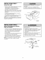
INSTALLATION
Install
the
STEP
7
Light
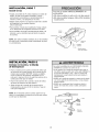
To prevent possible OVERHEATING
of the endpanel or
light socket,
• DO NOT use short neck or specialty light bulbs.
• DO NOT use halogen bulbs. Use ONLYincandescent.
• Install a 75 watt maximum light bulb in the socket.
The light will turn ON and remain lit for
approximately 4-1/2 minutes when power is
connected. Then the light will turn OFR
• Apply slight pressure on the sides of the lens and
slide the tabs into the slots in the end panel (See
illustration).
Lens Guide
• To remove, reverse the procedure. Use care to
avoid snapping off lens tabs.
Light
• If the bulb burns out prematurely due to vibration,
replace with a Garage Door Opener bulb.
NOTE: Use only a standard light bulb. The use of a
short neck or speciality light bulb may overheat the
endpanel or light socket.
"75Watt Max.
Light Bulb
INSTALLATION
STEP
Attach
the Emergency
Rope and Handle
8
Release
To prevent possible SERIOUSINJURY or DEATHfrom a
falling garage door:
• If possible, use emergency releasehandle to
disengage trolley ONLYwhen garage door is CLOSED.
Weak or broken springs or unbalanced door could
result in an open door falling rapidly and/or
unexpectedly.
• Thread one end of the rope through the hole in the
top of the red handle so "NOTICE" reads right side
up as shown. Secure with an overhand knot at
least 1" (25 mm) from the end of the rope to
prevent slipping.
• NEVERuse emergency releasehandle unless garage
doorway is clear of persons and obstructions.
• NEVERuse handle to pull door open or closed. If rope
knot becomes untied, you could fall.
• Thread the other end of the rope through the hole
in the release arm of the outer trolley.
• Adjust rope length so the handle is 6 feet (1.8 m)
above the floor. Secure with an overhand knot.
NOTE: If it is necessary to cut the rope, heat seal
the cut end with a match or lighter to prevent
unraveling.
Tro,,
Release Arm
Rope
£
Overhand
Knot
18
_
v
_
,_
Emergency
Release Handle
INSTALLATION
Electrical
STEP
9
Requirements
To prevent possible SERIOUSINJURYor DEATHfrom
electrocution or fire:
To avoid installation difficulties, do not run the
opener at this time.
• Be sure power is not connected to the opener,and
disconnect power to circuit BEFOREremoving cover to
establish permanent wiring connection.
• Garage door installation and wiring MUST be in
compliance with all local electrical and building codes.
• NEVERuse an extension cord, 2-wire adapter, or
change plug in any way to make it fit outlet. Be sure
the opener is grounded.
To reduce the risk of electric shock, your garage door
opener has a grounding type plug with a third
grounding pin. This plug will only fit into a grounding
type outlet. If the plug doesn't fit into the outlet you
have, contact a qualified electrician to install the
proper outlet.
PERMANENT WiRiNG
CONNECTION
Ground Tab
If permanent wiring is required by your local
code, refer to the following procedure.
Green
Ground Screw
To make a permanent connection through the 7/8"
hole in the top of the motor unit:
• Remove the motor unit cover screws and set the
cover aside.
Ground Wire
• Remove the attached 3-prong cord.
White Wire
• Connect the black (line) wire to the screw on the
brass terminal; the white (neutral) wire to the
screw on the silver terminal; and the ground wire
to the green ground screw. The opener must be
grounded.
• Reinstall the cover.
To avoid installation
opener at this time.
difficulties,
do not run the
19
Wire
INSTALLATION
Install
The
STEP
Protector
10
System
®
Be sure power is not connected to the garage door
opener BEFOREinstalling the safety reversing sensor.
To prevent SERIOUSINJURY or DEATHfrom a closing
garage door:
• Correctly connect and align the safety reversing
sensor. This required safety device MUST NOT be
disabled.
The safety reversing sensor must be
connected and aligned correctly before the
garage door opener will move in the down
direction.
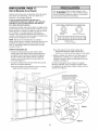
IMPORTANT INFORMATION ABOUT
THE SAFETY REVERSING SENSOR
• Install the safety reversing sensor so beam is NO
HIGHERthan 6" (15 cm) above garage floor.
When properly connected and aligned, the sensor
will detect an obstacle in the path of its electronic
beam. The sending eye (with an green indicator
light) transmits an invisible light beam to the
receiving eye (with a green indicator light). If an
obstruction breaks the light beam while the door is
closing, the door will stop and reverse to full open
position, and the opener lights will flash 10 times.
If it is necessary to mount the units on the wall, the
brackets must be securely fastened to a solid
surface such as the wall framing. Extension brackets
(see accessories) are available if needed. If
installing in masonry construction, add a piece of
wood at each location to avoid drilling extra holes in
masonry if repositioning is necessary.
The units must be installed inside the garage so
that the sending and receiving eyes face each
other across the door, no more than 6" (15 cm)
above the floor. Either can be installed on the left
or right of the door as long as the sun never
shines directly into the receiving eye lens.
The invisible light beam path must be unobstructed.
No part of the garage door (or door tracks, springs,
hinges, rollers or other hardware) may interrupt the
beam while the door is closing.
The mounting brackets are designed to clip onto
the track of sectional garage doors without
additional hardware.
6" (15 cm) max,
above floor
Sensor Beam
6" (15 cm) max,
above floor
Protection Area
Facing the door from inside the garage
2O
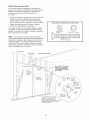
INSTALLING THE BRACKETS
Figure 1
Figure 1, 2 and 3 show recommended assembly of
bracket(s) and "C" wrap based on the wall
installation of the sensors on each side of the garage
door as shown on page 20, or on the garage door
tracks themselves.
Garage WALL or DOOR Track Installation
Mounting Bracket
With Square Holes
"C" Wrap
i /
L
i/'
Figure 4 and 5 are variations which may fit your
installation requirements better. Make sure the
wraps and brackets are aligned so the sensors
will face each other across the garage door.
Screws
# 10-32x3/8"
Lock Nuts
#10-32
Figure 2
Garage WALL Installation
Garage Wall or Door Track Installation
Lag Screws
1/4x1-1/2"
1. Fasten the "C" wraps to the mounting brackets
having square holes, using th hardware shown in
Figure 1.
Carriage Bolts1/4-20x1/2"
(with square shoulder)
Garage Wall Installation
2. Connect each assembly to a slotted bracket, using
the hardware show on Figure 2. Note alignment
of brackets for left and right sides of door.
"C" Wrap
3. Finger tighten the lock nuts.
Mounting Bracket
with Square Holes
4. Use bracket mounting holes as a template to
locate and drill (2) 3/16" diameter pilot holes on
both sides of the garage door, 4"-6" above the
floor but not exceeding 6" (see warning on
page 20).
5. Attach bracket assembly with 1/4"xl-1/2"
screws as shown in Figure 2.
Lock Nuts
1/4"-20
Figure 3
Lock Nuts 1/4"
Garage
Door Track
6. Adjust right and left bracket assemblies to the
same distance out from mounting surface. Make
sure all door hardware obstructions are cleared.
Tighten the nuts securely.
Alternate
Mounting Bracket
with Square Holes
J
Drill 3/8"
Holes
Shaped
Wrap
Garage Door Track Installation
Discard slotted bracket. Drill 3/8" holes in each track
and fasten securely with hardware as shown in
Figure 3.
Figure 4
Garage DOOR Track Installation
lag
Carriage Bolts
1/4-20xl/2"
j
Wall Mount
Alternate
Figure 5
Sensor
Floor Mount
with wire
Indicator
Mounting
I 1[_-LL J
with
I L._'_L_
Slot
Light
Bracket
Mounting
Mounting
Bracket
with
Square
Bracket
uare Holes
Holes
Mounting
with Slot
Bracket
'C" Wrap
Attach
Sensor
concrete
with wire
with
anchors
(not provided)
Floor
dtcator
Ltght
j
HARDWARE
©
Screw
#10-32x3/8"
_
SHOWN
ACTUAL
©
SIZE
I I I I I I I I ILLIgLIc!I!11!I!11_!/_2_
Lock Nut
#10x32
Staples
21
Carriage Bolts
1/4"-20xl/2"
Lock Nut
1/4"-20
MOUNTING AND WIRING THE SAFETY SENSORS
Figure 6
• Slide a 1/4"-20xl/2" carriage bolt head into the slot
on each sensor. Use wing nuts to fasten sensors to
brackets, with lenses pointing toward each other
across the door. Be sure the lens is not obstructed
by a bracket extension (Figure 6).
"C" Wrap
___
-_
Wing
Nut
Lndihtat_
Hex Bolt
• _
1/4-20 x 1-1/2"_
_
_ _-_
\" _
• Finger tighten the wing nuts.
• Run the wires from both sensors to the opener. Use
insulated staples to secure wire to wall and ceiling.
"_"
TROUBLESHOOTING
• Strip 1/4" (6 mm) of insulation from each set of
wires. Separate white and white/black wires
sufficiently to connect to the terminal screws: white
to 2 and white/black to 3 (Figure 7).
THE SAFETY SENSORS
1. If the sending eye indicator light does not glow
steadily after installation, check for:
• Electric power to the opener.
• A short in the white or white/black wires. These
can occur at staples, or at opener connections.
ALIGNING THE SAFETY SENSORS
• Plug in the opener. The indicator lights in both the
sending and receiving eyes will glow steadily if
wiring connections and alignment are correct.
• Incorrect wiring between sensors and opener.
• A broken wire.
2. If the sending eye indicator light glows steadily but
the receiving eye indicator light doesn't:
The sending eye green indicator light will glow
regardless of alignment or obstruction. If the green
indicator light in the receiving eye is off, dim, or
flickering (and the invisible light beam path is not
obstructed), alignment is required.
• Check alignment.
• Check for an open wire to the receiving eye.
3. If the receiving eye indicator light is dim, realign
either sensor.
• Loosen the sending eye wing nut and readjust,
aiming directly at the receiving eye. Lock in place.
NOTE: When the invisible beam path is obstructed
or misaligned while the door is closing, the door will
reverse. If the door is already open, it will not close.
The opener lights will blink 10 times. (If bulbs are not
installed, 10 clicks can be heard.) See page 20.
• Loosen the receiving eye wing nut and adjust
sensor until it receives the sender's beam. When
the green indicator light glows steadily, tighten the
wing nut.
Connect Wire to
Terminal Screws
Figure 7
Finished
Ceiling
Bell Wire
Bell Wire
Door Control
Connections____
(dotted line)
Sensor
Connections
"_--_
OPENER TERMINAL
Sensor
invisible Light Beam
Sensor
Protection
Area
22
SCREWS
INSTALLATION
Fasten
the
Door
STEP
11
Bracket
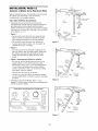
Fiberglass,aluminum or lightweight steel garage doors
WILL REQUIREreinforcement BEFOREinstallation of
door bracket. Contact your door manufacturer for
reinforcement kit.
Follow instructions which apply to your door type
as illustrated below or on the following page.
A horizontal reinforcement
brace should be long
enough to be secured to two vertical supports. A
vertical reinforcement
brace should cover the
height of the top panel.
HARDWARE
©
The illustration shows one piece of angle iron as the
horizontal brace. For the vertical brace, two pieces of
angle iron are used to create a U-shaped support
(Figure 1). The best solution is to check with your
garage door manufacturer for an opener installation
door reinforcement kit.
ACTUAL
Nut 5/16"-18
NOTE: Many vertical brace installations provide for
direct attachment of the clevis pin and door arm. In
this case you will not need the door bracket; proceed
to Installation Step 12.
SECTIONAL
SHOWN
SIZE
©
Lock Washer
5/16"
Carriage Bolt
5/16"-18x2-1/2"
DOORS
• Center the door bracket on the previously marked
vertical centerline used for the header bracket
installation. Note correct UP placement, as
stamped inside the bracket (Figure 2).
• Position the bracket on the face of the door within
the following limits:
• Mark and drill 5/16" left and right fastening holes.
Secure the bracket as shown in Figure 1 if there is
vertical reinforcement.
If your installation doesn't require vertical
reinforcement but does need top and bottom
fastening holes for the door bracket, fasten as shown
in Figure 2.
A) The top edge of the bracket 2"-4" (5-10 cm)
below the top edge of the door.
B) The top edge of the bracket directly below any
structural support across the top of the door.
Header
j
Horizontal and vertical reinforcement
is needed for lightweight garage doors
(fiberglass, aluminum, steel,
doors with glass panel, etc).
Bracket
Vertical
Reinforcement
Vedica{
Centedine
of Garage
/door
Door
Bracket
Location
Carriage Bolt
5/16"-18x2-1/2"
Vertical
Door
Bracket
Lock
5/16"
of Garage
Door
of Door or
Reinforcement
Door
Door Bracket
Plate
23
Nut
5/16"-18
Figure 1
Figure 2
ONE-PIECE
DOORS
Please read and comply with the warnings and
reinforcement instructions on the previous page.
They apply to one-piece doors also.
• Center the door bracket on the top of the door, in
line with the header bracket as shown. Mark either
the left and right, or the top and bottom holes.
• Drill 5/16" pilot holes and fasten the bracket with
hardware supplied.
HARDWARE
SHOWN
ACTUAL
SIZE
If the door has no exposed framing, drill 3/16" pilot
holes and fasten the bracket with 5/16"x1-1/2" lag
screws (not provided) to the top of the door.
Nut 5/16"-18
NOTE: The door bracket may be installed on the top
edge of the door if required for your installation.
(Refer to the dotted line optional placement drawing.)
Drill 3/16" pilot holes and substitute 5/16"x1-1/2" lag
screws (not provided) to fasten the bracket to the
door.
LockWasher
5/16"
Carriage Bolt
5/16"-18x2-1/2"
Header Wall
2x4 Support
--
Finished
Ceiling
/
Header
Bracket
--
Horizontal and vertical
reinforcement is needed for
lightweight garage doors
(fiberglass, aluminum, steel,
door with glass panel, etc.).
(Not Provided)
Door
Bracket
Optional
Placement
of Door
Bracket
Centefline of
Garage Door
Lock Washer
5/16"
Door
Bracket
• Top of Door
(inside
of Door
Optional
Placement
Carriage Bolt
5/16%18x2-1/2"
For a door with no exposed framing,
or for the optional installation, use
5/16 i'x1-1/2" lag screws (Not Provided)
to fasten door bracket.
24
_
6
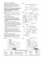
INSTALLATION
Connect
Door
STEP
Arm
12
Inner Trolle
to Trolley
Follow instructions which apply to your door type as
illustrated below and on the following page.
/
i@
/"
in
SECTIONAL DOORS ONLY
Ring
Fastener
• Make sure garage door is fully closed. Pull the
emergency release handle to disconnect the outer
trolley from the inner trolley. Slide the outer trolley
back (away from the door) about 2" (5 cm) as
shown in Figures 1,2 and 3.
/
/
,,
/
/
@
Door
• Figure 1:
Bracket
_ol
//../"
- Fasten straight door arm section to outer trolley
with the 5/16"x1" clevis pin. Secure the
connection with a ring fastener.
- Fasten curved section to the door bracket in the
same way, using the 5/16"x1-1/4" clevis pin.
Straight
Door Arm
Curved
Door Arm
Clevis Pin
5/16"x1-1/4"
Figure 1
• Figure 2:
- Bring arm sections together. Find two pairs of
holes that line up and join sections. Select holes
as far apart as possible to increase door arm
rigidity.
• Figure 3, Hole alignment
alternative:
- If holes in curved arm are above holes in straight
arm, disconnect straight arm. Cut about 6"
(15 cm) from the solid end. Reconnect to trolley
with cut end down as shown.
- Bring arm sections together.
- Find two pairs of holes that line up and join with
bolts, lock washers and nuts.
Emergency
Release
Handle
%
• Proceed to Adjustment Step 1, page 27. Trolley will
re-engage automatically when opener is operated.
Bolts
5/16"-18x7/8"
Door Bracket
Figure 2
HARDWARE
©
1
Nut 5/16"-18
SHOWN
Lock Washer 5/16"
ACTUAL
Ring Fastener
o-1{
Clevis Pin
5/16"xl" (Trolley)
SIZE
Clevis Pin
5/16"x1-1/4"(Door
Washe_/o/
el
Bracket)
.ors
Hex Bolt
5/16"-18x7/8"
Z°7
....
@0
I
o_/
Figure 3
25
_ Cut This End
It
i
ML
ALL ONE-PIECE DOORS
Door
• Fasten the straight and curved door arm sections
together to the longest possible length (with a 2
or 3 hole overlap).
Clevis Pin
5/16"x1-1/4"
- Press the Door Control push button. The trolley
will travel to the fully closed position.
• On one-piece doors, before connecting the door
arm to the trolley, the travel limits must be
adjusted. Limit adjustment screws are located on
the left side panel as shown on page 27. Follow
adjustment procedures below.
decrease
- Manually close the door and lift the door arm to
the trolley. The arm should touch the trolley just
ahead of the door arm connector hole. Refer to
the fully closed trolley/door arm positions in the
illustration. If the arm is behind the connector
hole, adjust the limit further. One full turn equals
2" (5 cm) of trolley travel.
UP
- Turn the UP limit adjustment screw
counter-clockwise 4 turns.
3. Connect the door arm to the trolley:
• Close the door and join the curved arm to the
connector hole in the trolley with the remaining
clevis pin. It may be necessary to lift the door
slightly to make the connection.
- Press the Door Control push button. The trolley
will travel to the fully open position.
- Manually raise the door to the open position
(parallel to the floor), and lift the door arm to the
trolley. The arm should touch the trolley just in
back of the door arm connector hole. Refer to
the fully open trolley/door arm positions in the
illustration. If the arm does not extend far
enough, adjust the limit further. One full turn
equals 2" (5 cm) of trolley travel.
• Closed door adjustment:
travel limit
decrease
3urved
Door Arm
Figure 4
Figure 5:
• Open door adjustment:
travel limit
Straight
Arm
Bolts
5/16"-18x7/8
• Secure with a ring fastener.
procedures,
Nuts
5/16"-18
Lock
Washers
5/16"
• With the door closed, connect the straight door
arm section to the door bracket with the
5/16"xl -1/4" clevis pin.
2. Adjustment
Ring
Fastener
Bracket
1.Assemble the door arm, Figure 4:
• Secure with a ring fastener.
• Run the opener through a complete travel cycle.
If the door has a slight "backward" slant in full
open position as shown in the illustration,
decrease the UP limit until the door is parallel to
the floor.
NOTE: When setting the up limit on the following
page, the door should not have a "backward" slant
when fully open as illustrated below. A slight
backward slant will cause unnecessary bucking
and/or jerking operation as the door is being opened
or closed from the fully open position.
DOWN
- Turn the DOWN limit adjustment screw
clockwise 4 complete turns.
Figure 5
Inner Trolley
Connectomole
j_
i
_
-_'-----------
Emergency
Release Handle
Inner Trolley
o.... .-..]]]]
Open Door
L
Backward Slant (Incorrect)
26
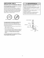
ADJUSTMENT
Adjust
Limits
the
UP and
STEP
DOWN
1
Travel
Without a properly installed safety reversal system,
persons (particularly small children) could be
SERIOUSLYINJUREDor KILLED by a closing garage
door.
Limit adjustment settings regulate the points at which
the door will stop when moving up or down.
• Incorrect adjustment of garage door travel limits will
interfere with proper operation of safety reversal
system.
• If one control (force or travel limits) is adjusted, the
other control may also need adjustment.
• After ANY adjustments are made, the safety reversal
system MUST be tested. Door MUST reverse on
contact with 1-1/2" (3.8 cm) high object (or 2x4 laid
flat) on floor.
To operate the opener, press the Door Control push
bar. Run the opener through a complete travel cycle.
• Does the door open and close completely?
• Does the door stay closed and not reverse
unintentionally when fully closed?
If your door passes both of these tests, no limit
adjustments are necessary unless the reversing test
fails (Adjustment Step 3, page 29).
Adjustment procedures are outlined below. Read the
procedures carefully before proceeding to
Adjustment Step 2. Use a screwdriver to make limit
adjustments. Run the opener through a complete
travel cycle after each adjustment.
To prevent damageto vehicles, be sure fully open door
provides adequate clearance.
NOTE: Repeated operation of the opener during
adjustment procedures may cause the motor to
overheat and shut off. Simply wait 15 minutes and
try again.
Cover
/_
NOTE: If anything interferes with the door's upward
travel it will stop. If anything interferes with the
door's downward travel (including binding or
unbalanced doors), it will reverse.
/
Limit
Adjustment
Screws
Protection
Bolt
HOW AND WHEN TO ADJUST THE LIMITS
Left Side Panel
• If the door does not open completely but opens
at least five feet (1.5 m):
Increase up travel. Turn the UP limit adjustment
screw clockwise. One turn equals 2" (5 cm) of
travel.
NOTE: To prevent the trolley from hitting the cover
protection bolt, keep a minimum distance of 2-4"
(5-10 cm) between the trolley and the boll
Adjustment
Label
• If door does not open at least 5 feet (1.5 m):
Adjust the UP (open) force as explained in
Adjustment Step 2.
If the door reverses when closing and there is
no visible interference to travel cycle:
• If the door does not close completely:
Increase down travel. Turn the down limit
adjustment screw counterclockwise. One turn
equals 2" (5 cm) of travel.
If the opener lights are flashing, the Safety
Reversing Sensors are either not installed,
misaligned, or obstructed. See Troubleshooting,
page 22.
If door still won't close completely and the trolley
bumps into the pulley bracket (page 4), try
lengthening the door arm (page 25) and
decreasing the down limit.
Test the door for binding: Pull the emergency
release handle. Manually open and close the door.
If the door is binding or unbalanced, call for a
trained door systems technician. If the door is
balanced and not binding, adjust the DOWN
(close) force. See Adjustment Step 2.
• If the opener reverses in fully closed position:
Decrease down travel. Turn the down limit
adjustment screw clockwise. One turn equals 2"
(5 cm) of travel.
27
ADJUSTMENT
Adjust
the
STEP
2
Force
Without a properly installed safety reversal system,
persons (particularly small children) could be
SERIOUSLYINJUREDor KILLED by a closing garage
door.
Force adjustment controls are located on the back
panel of the motor unit. Force adjustment settings
regulate the amount of power required to open and
close the door.
• Too much force on garage door will interfere with
proper operation of safety reversal system.
• NEVERincrease force beyond minimum amount
required to close garage door.
• NEVERuse force adjustments to compensate for a
binding or sticking garage door.
• If one control (force or travel limits) is adjusted, the
other control may also need adjustment.
• After ANY adjustments are made, the safety reversal
system MUST be tested. Door MUST reverse on
contact with 1-1/2" (3.8 cm) high object (or 2x4 laid
flat) on floor.
If the forces are set too light, door travel may be
interrupted by nuisance reversals in the down
direction and stops in the up direction. Weather
conditions can affect the door movement, so
occasional adjustment may be needed.
The maximum force adjustment range is about
3/4 of a complete turn. Do not force controls
beyond that point. Turn force adjustment controls
with a screwdriver.
NOTE: If anything interferes with the door's upward
travel, it will stop. If anything interferes with the
door's downward travel (including binding or
unbalanced doors), it will reverse.
HOW AND WHEN TO ADJUST THE FORCES
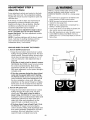
1. Test the DOWN (close) force
Force Adjustment
Controls
• Grasp the door bottom when the door is about
halfway through DOWN (close) travel. The door
should reverse. Reversal halfway through down
travel does not guarantee reversal on a 1-1/2"
(3.8 cm) obstruction. See Adjustment Step 3,
page 29.
If the door is hard to hold or doesn't reverse,
DECREASE the DOWN (close) force by turning
the control counterclockwise. Make small
adjustments until the door reverses normally.
After each adjustment, run the opener through a
complete cycle.
Back panel
'\
• If the door reverses during the down (close)
cycle and the opener lights aren't flashing,
INCREASE DOWN (close) force by turning the
control clockwise. Make small adjustments until
the door completes a close cycle. After each
adjustment, run the opener through a complete
travel cycle. Do not increase the force beyond
the minimum amount required to close the door.
\
\
ADJUSTMENT
LABEL
2. Test the UP (open) force
• Grasp the door bottom when the door is about
halfway through UP (open) travel. The door
should stop. If the door is hard to hold or
doesn't stop, DECREASE UP (open) force by
turning the control counterclockwise. Make small
adjustments until the door stops easily and
opens fully. After each adjustment, run the
opener through a complete travel cycle.
Open Force
• If the door doesn't open at least 5 feet (1.5 m),
INCREASE UP (open) force by turning the
control clockwise. Make small adjustments until
door opens completely. Readjust the UP limit if
necessary. After each adjustment, run the
opener through a complete travel cycle.
28
Close Force
ADJUSTMENT
Test
the
Safety
STEP
3
Reversal
System
Without a properly installed safety reversal system,
persons (particularly small children) could be
SERIOUSLYINJUREDor KILLED by a closing garage
door.
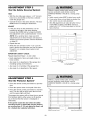
TEST
• With the door fully open, place a 1-1/2" (3.8 cm)
board (or a 2x4 laid flat) on the floor, centered
under the garage door.
• Safety reversal system MUST be tested every month.
• If one control (force or travel limits) is adjusted, the
other control may also need adjustment.
• After ANY adjustments are made, the safety reversal
system MUST be tested. Door MUST reverse on
contact with 1-1/2" (3.8 cm) high object (or 2x4 laid
flat) on the floor.
• Operate the door in the down direction. The door
must reverse on striking the obstruction.
ADJUST
• If the door stops on the obstruction, it is not
traveling far enough in the down direction
Increase the DOWN limit by turning the DOWN
limit adjustment screw counterclockwise 1/4 turn.
NOTE: On a sectional door, make sure limit
adjustments do not force the door arm beyond a
straight up and down position. See the illustration
on page 25.
• Repeat the test.
• When the door reverses on the 1-1/2" (3.8 cm)
board, remove the obstruction and run the opener
through 3 or 4 complete travel cycles to test
adjustment.
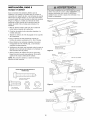
IMPORTANT SAFETY CHECK:
Repeat Adjustment Steps 1,2 and 3 after:
• Each adjustment of door arm length, limits, or
force controls.
• Any repair to or adjustment of the garage door
(including springs and hardware).
(or a 2x4 laid flat)
• Any repair to or buckling of the garage floor.
• Any repair to or adjustment of the opener.
ADJUSTMENT
Test
the
Protector
STEP
4
System
Without a properly installed safety reversing sensor,
persons (particularly small children) could be
SERIOUSLYINJUREDor KILLED by a closing garage
door.
®
• Press the remote control push button to open the
door.
• Place the opener carton in the path of the door.
-%
• Press the remote control push button to close the
door. The door will not move more than an inch,
and the opener lights will flash.
The garage door opener will not close from a remote
if the indicator light in either sensor is off (alerting
you to the fact that the sensor is misaligned or
obstructed).
If the opener closes the door when the safety
reversing sensor is obstructed (and the sensors
are no more than 6" (15 cm) above the floor), call
for a trained door systems technician.
Safet,
29
Reversing
Sensor
OPERATION
IMPORTANT SAFETY INSTRUCTIONS
To reduce the risk of SEVERE INJURY or DEATH:
1. READAND FOLLOWALL WARNINGSAND
INSTRUCTIONS.
9. If one control (force or travel limits) is adjusted, the
other control may also need adjustment.
10. After ANY adjustments are made, the safety reversal
system MUST be tested.
11. Safety reversal system MUST be tested every month.
Garagedoor MUST reverse on contact with 1-1/2"
(3.8 cm) high object (or a 2 x 4 laid flat) on the floor.
12. ALWAYSKEEPGARAGEDOORPROPERLYBALANCED
(see page 3). An improperly balanceddoor may not
reverse when required and could result in SEVERE
INJURYor DEATH.
2. ALWAYSkeep remote controls out of reach of children.
NEVERpermit children to operate or play with garage
door control push buttons or remote controls.
3. ONLYactivate garage door when it can be seen clearly, it
is properly adjusted, and there are no obstructions to
door travel.
4. ALWAYSkeep garage door in sight until completely
closed. NO ONESHOULDCROSSTHE PATHOFTHE
MOVING DOOR.
5. NO ONESHOULDGO UNDERA STOPPED,PARTIALLY
OPENDOOR.
13. All repairs to cables, spring assemblies and other
hardware, all of which are under EXTREMEtension,
MUST be made by a trained door systems technician.
14. ALWAYSdisconnect electric power to garage door
opener BEFOREmaking any repairs or removing
covers.
6. If possible, use emergency releasehandle to disengage
trolley ONLYwhen garage door is CLOSED.Weak or
broken springs or unbalanceddoor could result in an
open door failing rapidly and/or unexpectedly.
7. NEVERuse emergency release handle unless garage
doorway is clear of persons and obstructions.
8. NEVERuse handle to pull garage door open or closed. If
rope knot becomes untied, you could fall.
Using
Your
Garage
Door
SAVETHESEINSTRUCTIONS.
6. If obstructed while opening, the door will stop.
Opener
7. If fully open, the door will not close when the beam
is broken. The sensor has no effect in the opening
cycle.
Your Security÷ ® opener and hand-held remote control
have been factory-set to a matching code which
changes with each use, randomly accessing over
100 billion new codes. Your opener will operate with
up to eight Security÷ ® remote controls and one
Security÷ ® Keyless Entry System. If you purchase a
new remote, or if you wish to deactivate any remote,
follow the instructions in the Programming section.
If the sensor is not installed, or is misaligned, the
door won't close from a hand-held remote. However,
you can close the door with the Door Control, the
Outside Keylock, or Keyless Entry, if you activate
them until down travel is complete. If you release
them too soon, the door will reverse.
Activate your opener with any of the following:
• The hand-held Remote Control: Hold the large
push button down until the door starts to move.
• The wall-mounted Door Control: Hold the push
button or bar down until the door starts to move.
The opener lights will turn on under the following
conditions: when the opener is initially plugged in;
when power is restored after interruption; when the
opener is activated.
They will turn off automatically after 4-1/2 minutes.
Bulb size is 75 watts maximum.
• The Keyless Entry (See Accessories): If provided
with your garage door opener, it must be
programmed before use. See Programming.
When the opener is activated (with the safety
reversing sensor correctly installed and aligned)
1. If open, the door will close. If closed, it will open.
2. If closing, the door will reverse.
3. If opening, the door will stop.
4. If the door has been stopped in a partially open
position, it will close.
5. If obstructed while closing, the door will reverse. If
the obstruction interrupts the sensor beam, the
opener lights will blink for five seconds.
30
Using the Wall-Mounted
Door Control
THE MULTI-FUNCTION
To Open
the
Door
Manually
DOOR CONTROL
Press the push bar to open or close
the door. Press again to reverse the
door during the closing cycle or to
stop the door while it's opening.
Lighted
Push Button
To prevent possible SERIOUSINJURYor DEATHfrom a
falling garage door:
• If possible, use emergency releasehandle to
disengagetrolley ONLYwhen garage door is CLOSED.
Weak or broken springs or unbalanceddoor could
result in an open door falling rapidly and/or
unexpectedly.
• NEVERuse emergency release handle unless garage
doorway is clear of persons and obstructions.
• NEVERuse handle to pull door open or closed. If rope
knot becomes untied, you could fall.
The door should be fully
closed if possible. Pull down
on the emergency release
handle and lift the door
manually. To reconnect the
door to the opener, press the
door control push bar.
MANUAL DISCONNECT
POSITION
The lockout feature prevents
the trolley from reconnecting
automatically. Pull the
emergency release handle
down and back (toward the
opener). The door can then be
raised and lowered manually
as often as necessary. To
disengage the lockout feature,
pull the handle straight down.
LOCKOUT
POSITION
The trolley will reconnect on the next UP or DOWN
operation.
31
CARE
OF YOUR
MAINTENANCE
OPENER
Once a Month
LIMIT AND FORCE ADJUSTMENTS:
Weather conditions may
cause some minor changes
in door operation requiring
some re-adjustments,
particularly during the first
year of operation.
FORCE
CONTROLS
Pages 27 and 28 refer to the
LIMITCONTROLS
Only a screwdriver is
.imit and force adjustments.
required. Follow the
instructions carefully.
• Manually operate door. If it is unbalanced or
binding, call a trained door systems technician.
• Check to be sure door opens & closes fully. Adjust
limits and/or force if necessary. (See pages 27
and 28.)
• Repeat the safety reverse test. Make any
necessary adjustments. (See Adjustment Step 3.)
[_
Q_Q
Twice a Year
• Check chain tension. Disconnect trolley first. Adjust
if necessary (See page 11).
_'1
Once a Year
Repeat the safety reverse test (Adjustment
Step 3, page 29) after any adjustment of limits or
force.
• Oil door rollers, bearings and hinges. The opener
does not require additional lubrication. Do not
grease the door tracks.
THE REMOTE CONTROL BATTERY
To prevent possible SERIOUSINJURYor DEATH:
• NEVERallow small children near batteries
• If battery is swallowed, immediately notify doctor.
The lithium battery should
produce power for up to
5 years. To replace battery,
use the visor clip or
screwdriver blade to pry open
the case as shown. Insert
battery positive side up (+).
SCHEDULE
Open this end
first to aw_id/___
srask.ing _
_-_/_/
j_
hous_
Dispose of old battery properly.
NOTICE: To comply with FCC and or Industry Canada rules (IC), adjustment or
modifications of this receiver and/or transmitter are prohibited, except for changing the
code setting or replacingthe battery.THEREARENO OTHERUSERSERVICEABLE
PARTS.
Testedto Comply with FCCStandards FORHOMEOR OFFICEUSE.Operation is subject to
the following two conditions: (1) this device may not cause harmful interference, and
(2) this device must accept any interference received, including interference that may
cause undesired operation.
32
HAVING
A PROBLEM?
1. My door will not close
on my motor unit: The
must be connected and
garage door opener will
and the light bulbs blink
safety reversing sensor
aligned correctly before the
move in the down direction.
Bell Wire
• Verify the safety sensors are properly installed,
aligned and free of any obstructions. Refer to
Installation Step 10: Install The Protector
Systen_.
• Check diagnostic LED for flashes on the motor
unit then refer to the Diagnostic Charton the
following page.
2. My remotes will not activate the door:
• Reprogram remotes following the programming
instructions. Refer to Programming.
Safety Sensor
• If remote will still not activate your door, check
diagnostic LED for flashes on motor unit then
refer to Diagnostic Chart on the following page.
Sending Eye Safety Sensor
(Green Indicator Light)
3. My door reverses for no apparent reason:
Repeat safety reverse test after adjustments to
force or travel limits. The need for occasional
adjustment for the force and limit settings is normal.
Weather conditions in particular can affect door
travel.
Receiving Eye Safety Sensor
(Green Indicator Light)
\
5. My motor unit hums briefly:
• First verify that the trolley is against the stop bolt.
• Manually check door for balance or any binding
problems.
• Release the door from the opener by pulling the
Emergency Release Rope.
• Refer to Adjustment Step 2, Adjust the Force.
• Manually bring the door to a closed position.
• Loosen the chain by adjusting the outer nut4 to
5 turns. This relieves the tension.
4. My door reverses for no apparent reason after
fully closing and touching the floor: Repeat
safety reverse test after adjustments to force or
travel limits. The need for occasional adjustment for
the force and limit settings is normal. Weather
conditions in particular can affect door travel.
• Run the motor unit from the remote control or
door control. The trolley should travel towards
the door and stop. If the trolley re-engages with
the door, pull the Emergency Release Rope to
disengage.
• Refer to Adjustment Step 1, Adjust the UP and
DOWN Travel Limits. Decrease down travel by
turning down limit adjustment screw clockwise.
• Decrease the UP travel by turning the UP Travel
adjustment screw 2 full turns away from
the arrow.
• Re-tighten the outer nut so the chain is a
1/2" (13 mm) above the base of the rail. (When
the door is reconnected and closed, the chain
will sag. This is normal.)
• If the trolley does not move away from the bolt,
repeat the steps above.
33
Bell Wire
Your garage door opener is programmed with
self-diagnostic capabilities. The "Learn" button/diagnostic
LED will flash a number of times then pause signifying it
has found a potential issue. Consult Diagnostic Chart below.
Safety Sensor
Diagnostic
Chart
"0
Safety sensors wire open
(broken or disconnected).
Symptom: One or both of the Indicator lights on the safety sensors do
not glow steady.
• Inspect sensor wires for a short (staple in wire), correct wiring polarity
(black/white wires reversed), broken or disconnected wires, replace/attach
as needed.
OR
• Disconnect all wires from back of motor unit.
• Remove sensors from brackets and shorten sensor wires to 1-2 ft (30-60
cm) from back each of sensor.
• Reattach sending eye to motor unit using shortened wires. If sending eye
indicator light glows steadily, attach the receiving eye.
Safety sensors wire
shorted or black/white
wire reversed.
• Align sensors, if the indicator lights glow replace the wires for the sensors. If
the sensor indicator lights do not light, replace the safety sensors.
0
Door control or
wire shorted.
Symptom: LED is not lit on door control
• Inspect door control/wires for a short (staple in wire), replace as needed.
• Disconnect wires at door control, touch wires together. If motor unit
activates, replace door control.
• If motor unit does not activate, disconnect door control wires from motor
unit. Momentarily short across red and white terminals with jumper wire. If
motor unit activates, replace door control wires.
0
Safety Sensors
slightly misaligned
(dim or flashing LED).
Symptom: Sending indicator light glows steadily, receiving indicator
light is dim or flashing.
• Realign receiving eye sensor, clean lens and secure brackets.
• Verify door track is firmly secured to wall and does not move.
0
Motor overheated or
possible RPM sensor
failure. Unplug to reset.
Symptom: Motor has overheated; the motor unit does not operate or
trolley is stuck on stop bolt = Motor unit hums briefly; RPM Sensor =
Short travel 6-8" (15-20 cm).
• Unplug unit to reset. Try to operate motor unit, check diagnostic code.
• If it is still flashing 5 times and motor unit moves 6-8" (15-20 cm), replace
RPM sensor.
• If motor unit doesn't operate, motor unit is overheated. Wait 30 minutes and
retry. If motor unit still will not operate replace logic board.
0
Motor Circuit Failure.
Replace Receiver
Logic Board.
Symptom: Motor unit doesn't operate.
• Replace logic board because motor rarely fails.
34
PROGRAMMING
NOTICE: If this Security+® garage door opener is operated with a non-rolling code transmitter, the technical
measure in the receiver of the garage door opener, which provides security against code-theft devices, will be
circumvented. The owner of the copyright in the garage door opener does not authorize the purchaser or
supplier of the non-rolling code transmitter to circumvent that technical measure.
Your garage door opener has already been programmed at the factory to operate with your hand-held remote
control, The door will open and close when you press the large push button,
Below are instructions for programming your opener to operate with additional Security÷ ® remote controls,
To Add
USING THE "LEARN"
or Reprogram
a Hand.held
Remote
Control
BUTTON
1, Press and release the "learn"
button on the motor unit, The learn
indicator light will glow steadily for
30 seconds,
3. Release the button when the motor
unit lights blink, It has learned the
code, If light bulbs are not installed,
two clicks will be heard,
2. Within 30 seconds, press and hold
the button on the hand-held
remote* that you wish to operate
your garage door,
To Erase
All Codes From
Unit Memory
Motor
*3.Function
Remotes
If provided with your garage door opener, the large
button is factory programmed to operate it. Additional
buttons on any
Security÷ ® 3-Function
remote or compact
remote can be
programmed to operate
other Security÷ ®garage
door openers.
To deactivate any unwanted remote,
first erase all codes:
Press and hold the "learn" button on
motor unit until the learn indicator
light goes out (approximately 6 seconds), All previous
codes are now erased, Reprogram each remote or
keyless entry you wish to use,
35
To Add,
Reprogram
or
Change
a Keyless
Entry
PIN
NOTE: Your new Keyless Entry must be programmed to operate your garage door opener.
USING THE "LEARN"
BUTTON
1, Press and release the "learn"
button on motor unit. The learn
indicator light will glow steadily for
30 seconds,
3, Release the button when the
motor unit lights blink. It has
learned the code. If light bulbs are
not installed, two clicks will be
heard,
J
2, Within 30 seconds, enter a four
digit personal identification
number (PIN) of your choice on
the keypad. Then press and hold
the ENTER button,
To change an existing,
known PIN
Press the four buttons for your personal entry PIN
(not the last temporary PIN), then press and hold the
_-"button,
If the existing PIN is known, it may be changed by one
person without using a ladder,
1. Press the four buttons for the present PIN, then
press and hold the # button,
The opener light will blink twice, Release the #
button,
The opener light will blink three times. Release the
button.
2, Press the temporary 4-digit PIN you have chosen,
then press Enter,
The opener light will blink four times,
3. To set the number of hours this temporary PIN will
work, press the number of hours (up to 255), then
press ¢,
OR
2. Press the new 4-digit PIN you have chosen, then
press Enter,
The motor unit lights will blink once when the PIN has
been learned,
Test by pressing the new PIN, then press Enter. The
door should move.
To set a temporary
3. To set the number of times this temporary PIN will
work, press the number of times (up to 255), then
press #.
PiN
You may authorize access by visitors or service people
with a temporary 4-digit PIN. After a programmed
number of hours or number of accesses, this temporary
PIN expires and will no longer open the door. It can be
used to close the door even after it has expired, To set
a temporary PIN:
The opener light will blink once when the temporary PIN
has been learned,
Test by pressing the four buttons for the temporary PIN,
then press Enter. The door should move, If the
temporary PIN was set to a certain number of openings,
remember that the test has used up one opening,To
clear the temporary password, repeat steps 1-3, setting
the number of hours or times to 0 in step 3,
36
REPAIR
Rail
PARTS
Assembly
Parts
...........
KEY
NO.
1
2
3
4
5
6
Installation
Parts
KEY
NO.
PART
NO.
1
2
41A4166
41A6140-1
3
5
10A20
29B137
41A2828
6
7
8
9
41A4353
41B4494-1
178B35
41A4373A
4
15
16
10
11
12
13
14
15
16
12B374
12B380
12B483
12B484
12B485
12B776
178B34
41A3475-16
114A3130
I
37
PART
NO.
DESCRIPTION
4A1008
Master link kit
41A3489
1B3117
Complete trolley assembly
Rail center section
183B110
83All-2
Rail - end sections (each)
Rail Grease
41A3473
Chain & cable in dispensing
carton
41 B2616
Cable pulley bracket assembly
NOT SHOWN
41A2848
Rail assembly hardware kit
(see page 7).
DESCRIPTION
Door control button
3-function remote control housing
(no circuit board)
3V2032 Lithium battery
Transmitter visor clip
Emergency release rope & handle
assembly
Header bracket w/clevis pin & fastener
2-conductor bell wire - white & white/red
Curved door arm section
Safety sensor kit
(receiving and sending eyes)
with 3' 2-conductor bell wire attached
Door bracket
Door bracket plate
"C" wrap bracket
Square hole bracket
Slotted bracket
Hanging bracket
Straight door arm section
NOT SHOWN
Installation hardware bag (see page 7).
Owner's manual
Motor
Unit
Assembly
Parts
8
7
9
18
17
11
16
Brown
(Down)
Contact
Contact
KEY
NO.
1
2
PART
NO.
31 D380
41C4220A
41A2817
" _13
15
LIMIT SWITCH
ASSEMBLY
Contact
14
12
Wire
KEY
NO.
PART
NO.
DESCRIPTION
Sprocket cover
12
41D0328-4
Cover
Gear and sprocket assembly
Complete with: Spring washer,
thrust washer, retaining ring,
bearing plate, roll pins (2), drive
gear and worm gear, helical gear
w/retainer and grease
13
41A2818
Limit switch drive & retainer
14
41D3452
Limit switch assembly
15
41C4398A
RPM sensor assembly
16
41C4246
Wire harness assy. w/plug
17
41A2826
Shaft bearing kit
18
41A2822A
Interrupter cup assy.
19
41A5021-3H-315
Receiver logic board assy.
Complete with: Logic board,
end panel w/all labels
20
41A3691
DESCRIPTION
4
41 B4245
Drive/worm gear kit w/grease,
roll pins (2)
Line cord
5
41A4352
End panel w/all labels
6
4A 1344
7
108D58-2
Light socket
Lens
8
30B532
Capacitor - 1/2 HP
9
12A373
10
41A3150
Capacitor bracket
Terminal block w/screws
11
41 D3058
41A2825
Universal replacement motor &
bracket assembly
Complete with: Motor, worm,
bracket, bearing assembly, RPM
sensor
38
End panel w/all labels
NOT SHOWN
Opener assembly hardware kit
(includes screws not designated
by a number in illustration)
ACCESSORIES
139.53702
J
139.53687
139.53753
Emergency Key Release:
Required for a garage with NO
access door. Enables homeowner
to open garage door manually from
outside by disengaging trolley.
Premium Control Console:
139.53752
8 (2.4 m) Foot Rail Extension
10 (3 m) Foot Rail Extension:
139.53754
Support Brackets:
Multi-Function
Keyless Entry:
Enables homeowner to operate
garage door opener from outside
by entering a 4 digit code on
specially designed keypad.
139.53749
Plug-In Light Control:
Enables homeowner to turn on a
lamp, television or other appliance
from car, bedside, or anywhere in
the home with a remote.
139.53709
Door Clearance Brackets:
To allow a 10 (3 m) foot door to
open fully.
139.53589
Security÷ ®Compact 3-Function
Remote Control:
With loop for attaching key ring.
To allow an 8 (2.4 m) foot door to
open fully.
139.53705
Remote
Includes visor clip.
operation of garage door from
portable remotes. A light feature
Provides the
a lock
feature
to prevent
controls
opener
lights.
Can be
used to program the opener to
accept additional remotes.
139.53704
Security÷®3-Function
Control:
(For Sectional Doors Only)
For finished ceilings or where
additional support is required,
based on garage construction.
Includes brackets and fastening
hardware.
Replaces top brackets and rollers
on door to reduce height of door
travel. For use when installing
opener in garage with low
headroom clearance.
WARRANTY
SEARS WARRANTY
FULL 90-DAY WARRANTY
ON GARAGE
DOOR OPENER
For 90 days from the date of purchase, Sears will repair this Garage Door Opener, free of charge, if defective in material or workmanship.
LIMITED WARRANTY
From the 91st day up to 1 years from the date of purchase, Sears will furnish replacement parts for any defective parts, free of charge.
You pay for labor.
LIMITED WARRANTY ON MOTOR
From the 91st day and through 5 years, if the motor on this Garage Door Opener is defective, Sears will furnish a replacement motor,
free of charge. You pay for labor.
LIMITATION ON LIABILITY
SEARS WILL NOT BE LIABLE FOR LOSS OR DAMAGE TO PROPERTY OR ANY INCIDENTAL OR CONSEQUENTIAL LOSS OR
EXPENSE FROM PROPERTY DAMAGE DUE DIRECTLY OR INDIRECTLY TO THE USE OF THIS PRODUCT. Some states do not
allow the exclusion or limitation of incidental or consequential damages, so the above limitation or exclusion may not apply to you.
This warranty does not cover light bulbs or repair parts necessary because of operator abuse or negligence, including the failure to
install, adjust and operate this garage door opener according to instructions contained in the owner's manual.
WARRANTY SERVICE IS AVAILABLE BY CONTACTING THE NEAREST SEARS SERVICE CENTER IN THE UNITED STATES.
This warranty applies only while this product is in use in the United States.
This warranty gives you specific legal rights, and you may also have other rights which vary from state to state.
Sears, Roebuck and Co., Dept. 817WA, Hoffman Estates, IL 60179
39
CONTENIDO
Introducci6n
Revisi6n
2- 7
de los simbolos
y t_rminos
de seguridad ......... 2
Preparaci6n de la puerta de su cochera .........................
Herramientas necesarias .................................................
Planificaci6n
.................................................................
3
3
4-5
Inventario
de la caja de cart6n ........................................
6
Inventario
de piezas .........................................................
7
Mon
taje
Ensamble
8.11
el riel en y sujetar la m_nsula .........................
Ajustes
27.29
Ajuste el limite del recorrido .......................................... 27
Ajuste la fuerza .............................................................. 28
Pruebe el sistema de retroceso de seguridad ............... 29
Pruebe la Sistema de Protecci6n ®................................. 29
Operaci6n
30-34
Instrucciones de seguridad para la operaci6n ............... 30
C6mo usar su abridor de puerta de cochera ................. 30
8
C6mo usar la unidad de control de pared ..................... 31
Instalar el carro sobre el riel ............................................
9
C6mo abrir la puerta manualmente ............................... 31
Fijar riel al abridor ............................................................
9
Mantenimiento de su abridor de puerta de cochera ......32
Instale la cadena y cable y conecte el cubierta de
rueda dentada ................................................................
10
Apriete la cadena y cable ..............................................
11
Instalaci6n
Instrucciones de seguridad para la instalaci6n .............. 11
Determine d6nde va a instalar
la m_nsula del cabezal ................................................
12
......................................
13
Coloque
el riel en la m_nsula del cabezal .....................
14
Coloque
el abridor
en posici6n ......................................
15
Cuelgue
el abridor
.........................................................
16
Instale la unidad de control de la puerta .......................
Instale la luz ...................................................................
Instale la manija y la cuerda de emergencia
Requisitos
para la instalaci6n
Instale la Sistema
Fije la m_nsula
Conecte
el_ctrica
Tabla de diagn6stico ...................................................... 34
C6mo
11.26
Instale la m_nsula del cabezal
Si tiene algun problema ................................................. 33
17
18
Programar
el Abridor
35.36
C6mo agregar o reprogramar un control
remoto manual ............................................................... 35
C6mo borrar todos los c6digos ...................................... 35
Controles remotos de tres funciones ............................. 35
C6mo agregar, reprogramar o cambiar un C6digo de
entrada sin Ilave ............................................................. 36
Accesorios
37
Garantia
37
Nbmeros
de Servicio
Contratapa
................. 18
.........................
de Protecci6n ®.............................
de la puerta .....................................
el brazo de la puerta al trole ......................
19
20-22
23-24
25-26
INTRODUCClON
Revisi6n
de los Simbolos
de Seguridad
y T_rminos
Este abridor de puerta de cochera ha sido diseSado y probado para un funcionamiento seguro, siempre y cuando se instale,
se pruebe, se opere y se le de mantenimiento como se indica en este manual, cumpliendo al pie de la letra con todas las
advertencias e instrucciones generales aqu[ contenidas.
Mecanica
Electrica
Estas advertencias y/o simbolos de seguridad que
aparecen en este manual le alertaran de que existe el
riesgo de una lesion seria o de muerte si no se siguen
las instrucciones correspondientes. El peligro puede set
electrico (electrocucion) o mecanico. Lea las instrucciones
con mucho cuidado.
Cuando vea esta palabra y/o simbolo de seguridad en este
manual, le alertara de que existe el riesgo de daSar la
puerta de la cochera y/o el abridor si no se siguen las
instrucciones correspondientes. Lea las instrucciones con
mucho cuidado.
Preparaci6n
su Cochera
de la Puerta
de
Antes de comenzar:
• Quite los seguros
• Retire cualquier cuerda o cable que este conectado
a la puerta
• Haga la siguiente prueba con su puerta para verificar
que este balanceada y que no se atore ni se pandee:
1 Levante la puerta hasta la mitad de su recorrido como
se muestra Suelte la puerta Siesta balanceada,
debera mantenerse en esa posici6n con s61o el
soporte de los resortes.
Paraevitar LmaLESIONGRAVE
O INCLUSO
LA MUERTE:
• SIEMPRENamea un t6cnicoprofesionalparaquele d6
servicioa su puertadecocherasi _staseatora,sepandea,o
estAdesbalanceadaUnapuertade cocheraque no est_bien
balanceada
puedeno retrocedercomose requiere
• NUNCAintenteaflojar,moverni ajustarla puertade su
cochera,los resortesde la puerta,los cables,las poleas,las
m_nsulasni la tornillerfa,puestodos estoselementosest_n
bajotensi6nEXTREMA
• QuiteTODOSlossegurosy retireTODASlas cLierdas
conectadasa la puertadecocheraANTESde instalary operar
el abridordela puertade cocheraparaevitarqueseenreden
2. Suba y baje la puerta; observe si se atora con algo o
si se pandea.
Si su puerta se atora o se pandea, o no esta
balanceada Name a un tecnico especializado en
sistemas de puertas.
Paraevitarda_osa la puertay al abridor:
• SIEMPRE
quite los segurosANTESde instalary/o de operar
el abridor.
• SOLAMENTE
opereel abridorde puertade cocheracon
corrientede 120V,60Hzconobjetode evitarsu real
funcionamientoy queel abridorsedave.
Puerta seccional
Puerta de una sola pieza
Herramientas
Necesarias
Durante el montaje, instalaci6n y ajuste del abridor, las
instrucciones le indicaran usar las herramientas que
aparecen en la siguiente ilustraci6n.
Lapiz
oooo
Sierra de mano
Cinta de medir
Cortadorade alambre
Brocas de 3/16, 5/16
y 5/32de pulgada
Escalera
Destornillador
UO
7/16, 9/16 yl/4 de pulgad'a
Llave inglesa
Planificaci6n
_,Hay otra puerta que de acceso a ia cochera? Si no es
asf, sera necesario contar con el sistema de Nave de
emergencia Modeio 53702 Vea la pagina de Accesorios.
Identifique la aitura y el tipo de su puerta de cochera.
Revise el Area de su cochera y observe si alguna de
las siguientes instalaciones corresponden a la suya.
A veces se requieren materiales adicionales, asf que tal
vez sea conveniente tenet esta hoja y las ilustraciones
correspondientes a la mano cuando inicie la instalaci6n de
su abridor.
Observe el punto donde la puerta hace contacto con el
piso. El espacio entre la base de la puerta y el piso no
debe exceder 6 mm (1/4 de pulgada). Si no es asi, se
corre el riesgo de que el sistema de retroceso de
emergencia no funcione correctamente. Vea Ajustes,
Paso 3. Sera necesario reparar ya sea el piso o la
puerta.
Dependiendo de sus necesidades individuales, es posible
queen algunos casos vaya a necesitar materiales o
herramientas que no se incluyen con este producto.
INSTALACION
• Instalaci6n Paso 1 - Mire la pared o el techo encima de
la puerta de garaje. El parentesis de encabezamiento
debe ser abrochado seguramente a apoyos
estructu rales.
• Instalaci6n Paso 5 - Si el plaf6n o cielo raso de su
cochera tiene acabado, es posible que necesite una
mensula de soporte y/o mas pernos y tornillerfa para la
instalaci6n.
• Instalaci6n Paso 10 - Dependiendo del tipo de
construcci6n de su cochera, es posible que necesite
mensulas de extensi6n o bloques de madera para
instalar los sensores.
CON UNA PUERTA SECCIONAL
•
Si tiene una puerta de acero, aluminio, fibra de vidrio, o
con paneles de vidrio, necesitara refuerzos verticaies y
horizontales en la puerta. (Instalaci6n, Paso 11).
•
El abridor se debe instalar arriba del centro de la puerta,
pero si existe algQn resorte de tensi6n o placa de apoyo
en el paso de la mensula del cabezal, se puede instalar
hasta a 1.2 m (4 pies) a la derecha o a ia izquierda del
centro de la puerta. Vea Instalacion, Pasos 1 a111.
•
Si su puerta es de mas de 2.1 m (7 pies) de altura, vea
Extensiones de riel en la secci6n de Accesorios.
• Instalaci6n Paso 10 - El montaje en el piso del sensor
que activa el sistema de retroceso de seguridad podria
requerir piezas que no se incluyen.
INSTALACION
CON UNA PUERTA SECCIONAL
CIELO RASOCON ACABADO
Losrefuerzos verticalesy horizontales son
necesariospara las puertasde cochera de
materialesm_s livianos (fibrade vidrio, acero,
aluminio, o puertascon paneles de vidrio).
Vea la pagina 23, dondeencontraramas detalles.
i \,
Se requiere mensulade
soportey torniNoso
sujetadores.Veala pagina 16.
La holguraen la tension
de la cadenaes normal
cuandola puerta se
encuentracerrada
Pareddelantera
i
Unidaddel motor
Resortede extensi6n
Resortede torsi6n
Unidad de
control de
i
.--
la puerta,
instalada
Puertade
en la pared
acceso
Lfnea central
vertical dela
;=........
i
EN POSICION CERRADA
M_nsula
del cabezal
puerlade garaje
-
_D_'y
Trole
de la
/ /
puertade/ /
Cadena
cochera_J
/_/ Braze
_/recto de
_-_/U/lapuerta
J
\Sensordel sistema
de retrocesode seguridad
El espacio entrela base de
la puertay el piso no debe de
exceder 6 mm (1/4 de pulg.).
Sensor del sistema
de retrocesode seguridad
1_;"t
f
o
/'¢/
'
Iiberaci6n
/
Braze
la puerta
M_nsula
de la
puerta
Cuerday manija
delsietemade
deemergencia
'
Planificaci6n
INSTALACION
(continba)
CON PUERTAS DE UNA SOLA PIEZA
Sin un sistema de retroceso de seguridad que funcione
debidamente, al cerrar la puerta de la cochera se corre el
riesgo de que las personas (yen particular los ni_os
peque_os) sufran LESIONESGRAVESo INCLUSOLA MUERTE.
• El espacio entre la base de la puerta de la cochera y el piso
NO DEBEexceder 6 mm (1/4 de pulgada). De no ser as[, el
sistema de retroceso de seguridad no va a funcionar
debidamente.
• Generalmente una puerta de una sola pieza no requiere
refuerzos adicionales Si usted tiene una puerta de
material liviano y quiere reforzarla, consulte la
informaci6n respecto a puertas seccionales, contenida
en Instalaci6n, Paso 11
• Dependiendo del disefio de su puerta, tal vez necesite
piezas de montaje adicionales para la mensula de la
puerta (Paso 11)
• El piso o la puerta de la cochera SE DEBEreparar para
eliminar este espacio.
CIELO RASO CON ACABADO
PUERTA DE UNA SOLA PIEZA
SIN CARRIL
Se requieremensula d
y tomillos o sujetadores.
Vea la pagina 16.
Pared delantera
/
La holguraen la tension
de la cadenaes normal
cuandola puerta se
encuentracerrada
_/
Unidaddel motor
UnNad de control de la puerta,
instaladaen la pared
/
Puertade
acceso
EN POSIClONCERRADA
Pernode pare
de1trole
/
o
Cable
Trole
Cuerday manija
del sistemade
Sensor del sistemade
Sensor del sistemade
retrocesode seguddad
El espacioentre la base retrocesode seguridad
la puerta y el piso no debe de
exeeder6 mm (1/4 de pulg.)
Brazo
recto de
la puerta
-_.
PUERTA DE UNA PIEZA CON CARRIL
["-'_'rF-"-./n
Puerta de
la cochera
Brazo
curve
de la
emergencia
puerta
_J
La holguraen la tensi6n de la cadenaes normal
_
EN POSICIONCERRADA
I
I[
II
I
I II Ill
II [
Ill
@ [I
IIII
I
I
II
_
I
[......... I I
I
I
l[ Hill
II l_ll
]ll
Ill
II II1_ I
HIlll_ I
]
I
I
II _11
II I
II JIl__ I
I
V/A
Pernode pare
Cable
Trole
Cadena
F/A d?_re_e
o
ca
i;?a:
oci:u:e
ocS
J !
Rie,
I I Pae_t _
"-_u..lade Brazoreatode
_.L .... Cuerdaymanija
I I dela_'Duerta
.....
_
....
delsistemade
I
I ......
V///J
Puertade
V/A
ia_co_era
........
Iiberaci6n
,
de emergenaa
Inventario
de la Caja
de Cart6n
Su abridor viene empacado en dos cajas de carton que
contiene el motor y las piezas que se muestran en la
siguiente ilustracion. Tome nota de que los accesorios
dependera.n del modelo que haya comprado. Si falta
alguna pieza, revise con cuidado el material de empaque
ya queen ocasiones las piezas se atoran en el material de
Bot6nde control de la puerta
empaque. Toda la tornilleria y las piezas necesarias para el
montaje e instalacion de su puerta se ilustran en la
siguiente pagina. Conserve la caja y los materiales de
empaque hasta que la instalaci6n y el ajuste se hayan
terminado.
SECURITY+_'
Controlesremoto de 3 funciones
con clip parael visor (2)
Poleade lacadena
CubJertade la
rueda dentada
M_,nsulaspara colgar
Unidad
delmotorconunlente
Suporte
la
sPlo t : %erta
M_,nsuladel cabezal
Mordaza (2)
M6nsulade montaje de
sensorse segurNad de
inversi6n,con agujero
extendido(2)
M_nsuh para los sensores
del sistema de retrocesode
seguridad (2)
(2) Sensor del sistemade retroceso
de seguridad (1 ojo emisor y 1 ojo receptor)
conectadosa un cable de campana de dos conductores,
Blancoy Nanco/negro
Secei6ncurva del
brazo de la puerta
Etiquetas de
seguridad y
literatura
1
Secci6n recta del
brazode la puerta
Inventario
de Piezas
Antes de la instalacion, organice todas las piezas en grupos como se muestra en la siguiente ilustraci6n.
TORNILLERiA
Y PIEZAS PARA EL MONTAJE
i
Pemo conarandela
5/16-18xl/2 pulg. (2)
(montado en el abddor)
Pemohexagonal
de 5/16-18x7/8pulg. (3)
Pemodecoche
de 1/4-20xl/2pulg.(4)
Tuerca de
5/16 -18 pulg, (5)
Enlace maestro (2)
©
©
Tuercade
1/4-20X7/16pulg. (4)
Arandela de
5/16pLllg,(4)
Flecha roscada del trole (1)
TORNILLERJA Y PIEZAS PARA LA INSTALACION
©
©
Tomillo de cabeza cuadrada
de 5/16-9xl-5/8 de pulg. (2)
Pemo hexagonal
de 5/16-18x7/8pulg. (4)
Tuemade
5/16-18 pLllg,(6}
Tornillode cabeza cuadrada
de 5/16-18xl-7/8 pulg. (2)
1/4"-14x5/8"(2)
Anillo sujetador(3}
Pemo de coche de 5/16-18x2-1/2pulg, (2)
©
Pemo de ooche
de 1/4-20xl/2 pulg,(4)
Tuerca de
1/4-20 pulg. (4)
©
Pemo hexagonal
de 1/4-20x1-1/2"(2)
Tornillo#10-32X3/8 pLIIg,(4)
Manija
Taquete para murofaJso(2)
Pasador de chaveta
de 5/16x1-1/4 pulg, (1)
Pasadorde chaveta
de 5/16x2-3/4 pulg. (1)
Tornillo de cabeza cuadrada
de 1/4x1-1/2pulg, (4)
Arande[a de 5/16pulg. (6)
Tuerca de
#10X32 (4)
Cuerda
Pasadorde chaveta
de 5/16xl pulg. (1)
Tuema de rnariposa
1/4-20pLIIg.(2)
fl
Grapacon
material aislante
(80)
MONTAJE,
Ensamble
PASO
1
el Riel y Sujetar
la M_nsula
No encienda ni use el abridor hasta que Ilegue al paso
de la instalacibn correspondiente, de otra manera
corre el riesgo de complicar el proceso de instalacibn.
ESTAS PIEZAS SE MUESTRAN
©
1. Extender las tres secci6nes del riel en una superficie
plana.La secci6n frontal y posterior son intercambiables
para facilidad del ensamble.
Tuercade
1/4-20X7/16pulg.
2. Inserte los pernos con cabeza redonda y
cuello cuadrado para que los cuellos de
los pernos cuadrados se asienten en los
hoyos cuadrados de las secciones del
riel y pasen a trav_s de los hoyos
redondos en los tierantes del riel.
Asegt_rese que los cuellos de los
pernos esten asentados en los
orificios rectangulares y que los rieles
se encuentren alineados, antes de
apretar las contratuercas de
seguridad. El ensamblado incorrecto
puede ocasionar la operaci6n brusca del
carro y tambien movimientos de reversa de la puerta
ruidosos o molestos.
Pernode coche
de 1/4-20xl/2 pulg.
Pemohexagonal
Tuerca de
Arandela de
de_16-18xT/Spulg.
5/16 -18pulg.
5/16pulg.
3. Ensamble las tuercas de seguridad, alfnee y apriete.
NOTA: Si el riel no se ensamble exactamente como se
muestra, el carro no se movera suavemente a Io largo
del riel o golpeara contra los pemos.
4. Situar la mensula frente al final del riel con se muestra.
Fijar firmement con los tornillos indicados.
RIEL TRASERO
(HAClA ABRE-PUERTAS)
Riel
NOTA: AI apretar los pemos, asegurar que la mensula
se mantenga paralela al riel. De otra manera el riel
puede doblarse cuando este abriendo.
Tuercade
sequridad 1/4"
(Seeei6n final)
\
/
Brazosen
Riel
Brazes en
RM
Riel
(Secebn
eentro)
Pemo Hexagonal
5/16"-18x7/8"
Riel
(Seecionfinal)
%
M_nsulade poleade la cable
fijada FRENTEAL
FINAL del riel
Mensulade polea
dela cable
Escuadra delcarro
perforaci6n para
laflecha
EN SU TAMANO REAL
",,,
(HACIA LA PUERTA)
O
Arandela
5/16"
_),
Tuerca
5/16"
\
\
MONTAJE,
PASO 2
Instalar el Carro Sobre el Riel
Tuerca intema
5/16 pulg.
Arandelade
Tuerca extern5a16
A_
__'__
Espiga roscada
• Unir la espiga roscada con el carro con rondana y
tornillo come se muestra.
• Come un tope temporal, inserte un destomillador
del hoyo en la parte frontal al final del riel.
• Deslizar el carro ensamblado
topar con el destornillador.
dentro
a Io largo del riel hasta
NOTA: Si el carro se golpea contra alguna tuerca en el
riel, flecha y/o gufa y tuerca donde se unen per el lade o
puesto y deben ser puestas nuevamente en posicion
correct& Revisar Montaje Paso 1.
ESTAS PIEZAS SE MUESTRAN
EN SU TAMAI_IO REAL
©
Tope temporal
MONTAJE,
PASO
Fijar Riel al Abridor
5/16 -18 pulg.
ParaevitardaSosSERI0Sal abridor,SOLOutilizarpernos
montadosen la partesuperiordel motor.
• Colocar el abre abridor en el empaque del
material para proteger la cubierta. Per conveniencia,
colocar un soporte abajo de la mensula.
• Quitar los dos pernos con arandela montados en la parte
superior del motor.
Perno conarandela
5/16-18xl/2 pulg.
Pernohexagonal
• Alinear los orificios de la seccidn posterior del riel con
los orificios en el motor.
de 5/16-18x7/8pu,g.
\
Orificiodel tornillo _&_
de protection de
_
•
la oubierta _-_/_
Fijar el riel con los dos pernos previamente colocado y
ajustado firmemente.
iSblo se deben utilizar estos pernos! Cualquier otro
perno pueda ocasionar serios daSos al abridor.
Insertar el pemo hexagonal 5/16-18x7/8 de pulg. en el
orificio de la cubierta protectora en el riel tal come se
muestra. Apretar fuertement con una rondana 5/16 de
pulg. y una tuerca de 5/16 de pulg.
NOTA: Este perno evitar que el carro se desplace
demasiado. Mantener una distancia de un mfnimo de 5mm
(2 pulg.) entre el carre y este peme al ajustar los Ifmites
de desplazamiento (ver pagina 27).
ESTAS PIEZAS SE MUESTRAN
Perno hexagonal
de 5/16-18x7/8pulg.
Tuerca de
5/16 pulg.
3
No encienda ni use el abridor hasta que Ilegue al paso
de la instalacion correspondiente, de otra manera
corre el riesgo de complicar el proceso de instalacibn.
•
Arandelade
EN SU TAMAI_IO REAL
Tuerca de
5/16 -18 pulg.
Arandelade
5/16 pulg.
"_
_"_
'8'
(Secci6n
-_//
_
posterior)
_
I
/
Arandelade 5/16 pulg.
Tueroade
5/16-18 pulg.
_
I
_
MONTAJE,
Ilnstalar
Conecte
PASO
la Cadena
el Cubierta
INSTALACION
4
y Cable y
de Rueda
Para evitar posibles LESIONESGRAVESen los dedos causadas
por las partes m6viles del abridor de puerta de cochera:
• SIEMPRE mantenga las manos lejos de la rueda dentada
est6 funcionando el abridor
Dentada
DE LA CADENNCABLE
• Ponga la cubierta de la polea ANTES de hacer funcionar el
abridor.
1. Sacar el cable de la caja y sujetarlo al carro con un
enlace maestro de la caja de los accesorios (Figura 1).
• Empujar los pernos de la barra del enlace maestro a
traves del cable y del orificio en la parte delantera del
carro.
Cart@ para alimentar
• Empuje la tapa del enlace maestro sobre los pernos y
las ranuras de los pernos.
Dle_e_
,aeC_ede,_oa
Yelcartdn
• Deslice el resorte de clip sobre la tapa y sobre las
ranuras de los pernos hasta que los dos pernos esten
bien colocados y seguros en su lugar.
e se tuerzan.
2. Con el carro contra el destornillador, alimentar el cable
alrededor de la polea.
Mantengatensos el cable
y la cadenamientras los alimente.
3. ContinUe a Io reil y dirigirlo hacia adelante de la rueda
dentada del motor (Figura 2). Los dientes de la rueda
dentada necessite conectar con la cadena. Continue a
el perno roscado del carro.
Resorte de clip
del enlace maestro
Figura 1
Tapa del
enlace maestro
4. Utilizar el segundo eslab6n maestro para conectar la
cadena al extreme plane del eje con rosca (figura 1)
Comprobar y asegurarse que la cadena no este
torcida.
Resortede clip
del enlacemaestro
Extremo
piano
delpemoroscado
Tapadel _'\_
enlacemaestro "_
oadena
5. Quite el destornillador
Riel
Lazada
CUBIERTA DEL RUEDA DENTADA
del cable _.
Insertar la lengueta posterior en la ranura en la parte
posterior de la placa de montaje. Oprimir la cubierta
ligeramente y insertar la lengueta delantera (Figura 3).
Indentacion
j del perno
Barradel
Trob
_.j
Figura
3
Cubiertade la rueda
Polea de cable
Barra del
enlace maestro
_NSTALELA CADENA Y CABLE
EN ESTA DIRECCION
dentada de1 motor
Ranura de la
Ranurade la
fY__ _//
pestalia delantera
Placa cJe
.
montaje/_-
Figura 2
//_
10
Ruedadentada
del motor
/
enlace maestro
MONTAJE,
PASO
5
Apriete la Cadena y cable
Tuerca
extema
Paraapretar
\
Arandela
,
];Jercaintema
/
• Gire la tuerca interna y ajuste la arandela; baje ambas
por el eje roscado del trole, alejandolas del trole.
• Para aligerar la cadena, girar la tuerca externa en la
direcci6n mostrada. A la medida que gire la tuerca,
mantenga la cadena derecha.
• Una vez que la cadena este aproximadamente 13 mm
(1/2 pulg.) arriba de la base del riel en su punto medio,
vuelva a apretar la tuerca interna para asegurar el ajuste.
Si la cadena queda demasiado
puede hacer ruido.
Cadena
floja la rueda dentada
AI terminar la instalaci6n, es posible que note que la
cadena este caida cuando la puerta esta cerrada. Esto es
normal. Si la cadena regrese a la posici6n mostrada al
abrir la puerta, no vuelva a ajustar la cadena.
1/2"(13
mm)
Base delriel
NOTA: En el futuro, cuando le de mantenimiento
SlEMPRE tire de la manija de emergencia para
desconectar el trole antes de ajustar la cadena.
Ya termino de armar su abridor de puerta de cochera.
Lea les siguientes advertencias antes de continuar a la
seccion de instalacion.
INSTALACION
Para reducir el riesgo de una LESION GRAVE o
LA MUERTE:
1. LEA Y SIGA AL PIE DE LA LETRATODAS LAS
INSTRUCCIONESPARA LA INSTALACION.
8. NUNCAIleve puestos relojes, anillos ni ropa muy floja
mientras est6 instalando o dando servicio al abridor, pues
podrian atorarse en la puerta de la cochera o en los
mecanismos del abridor.
9. Instale el control de pared de la puerta de cochera:
• de manera que quede a la vista desde la puerta de
la cochera
• fuera del alcance de los ni_os y a una altura minima de 5
pies (1.52 m)
• lejos de todas las partes mOviles de la puerta.
10. Coloquelacalcomaniaqueadviertesobre el riesgode atraparse
cercadel control de la puertade la cochera,en la pared.
11. Coloque la calcomania que contiene la prueba de retroceso
de seguridad y liberaciOn de emergencia a plena vista en la
parte interior de la puerta de la cochera.
12. AI concluir la instalaciOn, prBebe el sistema de retroceso de
seguridad. La puerta DEBEretroceder al entrar en contacto
con Bn objeto de 3.8 cm (1-1/2 pulg.) o bien con Lmpedazo
de madera de 5 x 10 cm (2x4 pulg.) puesto piano sobre el
piso.
2. Instale el abridor de pBerta de cochera solo si la puerta de la
cochera est,. debidamente balanceaday lubricada. Si la puerta
no est,, debidamente balanceadaes posible que no retroceda
cuando se requiera, Io que podria ocasionar una LESION
GRAVEo INCLUSOLA MUERTE.
3. Todaslas reparacionesde los cables, resortes y otras piezas
las DEBEIlevar a cabo un t_cnico especializadoen sistemas
de puertas, ANTESde instalar el abridor.
4. Quite todos los seguros y retire todas las cuerdas conectadas
a la puerta de la cochera ANTESde instalar el abridor para de
evitar que se enreden.
5. Instale el abridor de la puerta de cochera a una distancia de
2.13 m (7 pies) del piso.
6. Monte la manija de liberaciOn de emergencia a una distancia
de 1.83 m (6 pies) del piso.
7. NUNCAconecte elabridor de la puerta de cocheraa unafuente
de energiael_ctrica hasta que asi se indique.
11
INSTALAClON,
Determine
la M_nsula
PASO
_NSTALACIONOPCIONAL DE
1
LAM NSULA
DEL
CABEZAL
EN EL CIELO RASO
ddnde
va a instalar
del Cabezal
Cielorass
sin aeabado
Pared
delantsra
ParaevitarunaposibleLESIONGRAVE
o INCLUSO
LA MUERTE:
• La m_nsuladel cabezalDEBEquedarR[GIDAMENTE
sujeta
al soporteestructuralen la pareddelanterao en el cielo
raso,de no serasfes posiblequela puertade la cocherano
retrocedacuandose requiera.NOinstalela m_nsuladel
cabezalen murosfalsos.
• Se DEBENusarsujetadoresparaconcretosi el montajede la
m_nsuladel cabezalo del pedazode maderade 5x10cm
(2x4 pulg.)sehaceen mamposterfa.
• NUNCAtratede aflojar,moverni ajustarla puertade la
cochera,los resortes,los cables,las poleas,lasm6nsulasni
la tornilleria,puestodasestaspiezasest_nbajo unatensi6n
EXTREMA.
• SIEMPRE
Ilamea unt_cnicoespecializado
en sistemasde
puertassi ]a puertade cocherase pandea,seatorao si estA
desbalanceada.
Unapuertade cocheraqueno est6
balanceada
puedeno retrocedercuandoserequiera.
Linea central
vertical de ]a
puerta de garaje
\\
Pedazo de madera
de 5x10 em (2x4 pulg)
Soportss de
la estructura
El proceso de instalaci6n varia dependiendo de los
diferentes tipos de puerta de cochera. Siga las
instrucciones que correspondan a su puerta.
1. Cierre la puerta y marque la linea central vertical del
interior de la puerta.
2. ContinQe marcando esta linea hacia arriba hasta Ilegar
a la pared delantera, por encima de la puerta.
Es posible instalar la mensula del cabezal hasta una
distancia maxima de 1.22 m (4 pies) a cada lado del
centre de la puerta, pero unicamente si un resorte
de torsion o un placa central de apoyo se encuentra
en el recorrido. Tambien cuando el espacio es
reducido, se puede instalar la meneula en el cielo
raso o plafon de la cochera (vea la pagina 13).
(Asimismo, se puede instalar invertida sobre la
pared si es necesario, esto le dara aproximadamente
1 cm (1/2 pulg.) de espacio).
Si necesita instalar la mensula del cabezal en un
pedazo de madera de 5x10 cm (2x4 pulg.) (ya sea en la
pared o en el techo), use tornillos de cabeza cuadrada o
pijas (no se incluyen) para sujetar el pedazo de madera
a los soportes estructurales, como se indica aqui yen la
pa.gina 13.
Pareddelantsra
"_.....
r- (2 pulg.) fiardl
Pared delantera
I
Puntomilsalto
delreeorfido
Carfil
del reeorfido
Puerta
Puerta secoiona_ con oarrH curvo
3. Abra la puerta hasta el punto mas alto de su recorrido
come se muestra. Marque una linea horizontal que
intersecte en la pared delantera y adel punto ma.s alto
del recorrido:
Puerta de aria so_a pieza con
carriJ horizontal
Pareddelantera
', 20 cm (8 pulg.)
lantera
(8 pulg.)
• 5 cm (2 pulg.) por encima del punto ma.s alto en el
case de puertas seccienales y puertas de una sola
pieza con riel.
i', alto dsl
i', rsesrdds
Puerta
• 20 cm (8 pulg.) per encima del punto mas alto en el
case de puertas de una sola pieza sin riel.
dsl
A esta altura, el extremo superior de la puerta tendra.
suficiente espacio para su recorrido.
NOTA: Si el nSmero total de centfmetros excede la
altura disponible en su cochera, use la altura maxima
pesible o consulte la pagina 13 para la Instalacion en el
cielo rase e plafon.
',
II
fl'loRtante
Puerta de una sola pieza sin carrii:
tomHleria deI montante
12
Puerta de una pieza sin carrie
torniHeria dei pivete
INSTALACION,
Instale
la M_nsula
PASO
2
Montajeenlapared
',_
del Cabezal
Este orificio es solamente
para marcarla posicion de
la mensula.Se deben de
utilizar lostornillos tirafondo
para sujetar la m_nsula.
La mensula del cabezal se puede fijar a la pared justo por
encima de la puerta de la cochera o en el cielo raso Siga
las instrucciones que sean mas adecuadas para su
cochera No instale la mensula del cabezal en un muro
falso. Si va a fijar la mensula del cabezal a ladrillo o
mamposteria,
asegurese de utilizar sujetadores de
cemento (no se incluyen).
INSTALACl0N
DE LA MI_NSULA DEL CABEZAL
PARED DELANTERA
Orificiosopcionales
para la instalaci6n
EN LA
Lineacentral
vertical de la
puerta de garaje
• Coloque la mensula sobre la Ifnea central vertical con el
borde inferior sobre la Ifnea horizontal, como se muestra
en la ilustracion (con la flecha de la mensula apuntando
hacia el techo)
• Marque los orificios de la mensula que van en Ifnea
vertical Taladre los orificios con una broca de 3/16 de
pulgada y sujete la mensula al soporte de la estructura
con la tomilleria que se incluye
_
Pared
delantera
Tornillosde cabeza
cuadradade
5/16xgxl-5/8 pulgadas
Pedazo de
madera de
5x10 cm
(2x4 pulg.)
Linea
horizontales----,_"
Resortede la puerta
/
/
/
ESTAS PIEZAS SE MUESTRAN
TAMAi_IO REAL
/
EN SU
/
-
Puntomilsaltodel
recorrido
delapuerta
delacochera
Puertadela cochera -
vertical de la
puerta de garaje
de 5/16 per 9xl-5/8 pulgadas
INSTALACION
CIELO RASO
DE LA M#NSULA
DEL CABEZAL EN EL
• Extienda la linea central vertical sobre el cielo raso
como se muestra en la ilustracion
• Coloque la mensula en el centro de la Ifnea a no mas
de 15 cm (6 pulg) de la pared Cercidrese de que la
flecha de la mensula apunte hacia el lado opuesto de la
pared La mensula puede set instalada pegada al cielo
raso cuando el espacio es muy reducido
• Marque ddnde va a taladrar los orificios laterales
Taladre los orificios con una broca de 3/16 de pulgada y
fije la mensula firmemente al soporte de la estructura
con la tomilleria que se incluye
_
__
cabezal
/_
- Cielo
raso con acabadoLineacentral
veCdcalde la puertade garaje
_._;;_
Maximede 15 em (6 puig.)
Resorte de
la puerta
Orificiospara la instalaci6n
enel cielo raso
cuadrada de
_/16x9xl-5/8pulgadas
Pared delantera
para marcarla posici6n de
la m_nsula. Se debende
utilizar los tornillostirafondo
para sujetar la mensula.
- Linea central
Verticalde la
puerta de garaje
13
INSTALACION,
PASO
Coloque
el Riel
del Cabezal
3
en la M_nsula
• Coloque el abridor sobre el piso de la cochera debajo
de la mensula del cabezal Use el hule espuma del
empaque como base para protegerlo NOTA: Si el
resorte de la puerta esta obstruyendo, va a necesitar
ayuda Otra persona tendra que sostener el abridor
firmemente sobre un soporte temporal para ayudarle a
que el riel pueda librar el resorte
jJ
• Coloque la mensula del riel junto a la mensula
del cabezal
Mensuladel cabezal
• Alinee los orificios de las mensulas y jQntelas con un
pasador de chaveta como se muestra en la ilustraci6n
Polea Ioca
• Sujetelos con un anillo sujetador
del
cabezal
Riel
Pasador de Chaveta
5/16'x2-3/4"
poba de
la cane
Riel
Puertade
lacochera
Caja del abridor
o soporte temporal
ESTAS PIEZAS SE MUESTRAN
EN SU TAMAI_IO REAL
ol 0
Pasador de chaveta
de 5/16x2-3/4 pulg.
Anillo sujetador
14
INSTALACION,
Coloque
PASO
el Abridor
4
en Posici6n
Para evitar que la puerta de cochera sufra daSos, apoye el riel
del abridor de la puerta de cochera sobre un pedazode madera
de 5x10 cm (2x4 pulg.) colocado en la secciOnsuperior de la
puerta.
Siga ias instrucciones correspondientes al tipo de puerta
de su cochera, como se muestra en la ilustraci6n.
PUERTA SECCIONAL
CON CARRIL
O PUERTA DE UNA SOLA PIEZA
Un pedazo de madera de 5x10 cm (2x4 pulg.) le sera de
ayuda al determinar la distancia ideal entre la puerta
y el riel.
i iiiiii iiiii!
• Retire la espuma de embalaje.
RM
• Ponga el abridor sobre la escalera; si la escalera no es
Io suficientemente alta, va a necesitar ayuda.
• Abra completamente la puerta y coloque el pedazo de
madera de 5x10 cm (2x4 pulg.) en la secci6n superior,
de manera que quede debajo del riel.
• Si el panel superior golpea el trole al levantar la puerta,
tire hacia abajo el brazo de liberaci6n del trole para
desconectar las secciones interna y externa del mismo.
Deslice el trole externo hacia el motor. El trole puede
permanecer desconectado hasta el final del Paso 12 de
la secci6n de Instalaci6n.
Brazode
]iberaci6n -del trole
CONECTADO
SUELTO
PUERTA DE UNA SOLA PIEZA SIN CARRIL
Coloque un pedazo de madera de 5x10 cm (2x4 puig.)
sobre su lado de ayuda al determinar la distancia ideal
entre la puerta y el riel.
•
Retire la espuma de embalaje.
•
Ponga el abridor sobre la escalera; si la escalera no es
Io suficientemente alta, va a necesitar ayuda.
F
• Abra completamente la puerta y coloque un pedazo de
madera de 5x10 cm (2x4 pulg.) sobre su lado en la
secci6n superior, de manera que quede debajo del riei.
• La parte superior de la puerta debe estar alineada con
la parte superior de la unidad del motor. No instale el
abridor a ma.s de 10 cm (4 puig.) por encima de este
punto.
15
I
INSTALACION,
Cuelgue
el
PASO
5
Abridor
Para evitar la posibilidad de una LESIONGRAVEsi se cae el
abridor de la puerta de cochera, sujOteloFIRMEMENTEa los
soportes estructurales de la cochera. Se DEBENusar
sujetadores para concreto si alguna de las mOnsulasse va a
instalar en mamposteria.
Aquf se muestran tres ejemplos distintos para la
instalaci6n; sin embargo, es posible que su cochera no
concuerde con ningune de ellos. Las mensulas de soporte
deben estar en angulo (Figura 1), para que proporcienen
un soporte rfgido. En caso de tenet un cielo raso acabado
(Figura 2 y Figura 3), instale una mensula de metal
resistente en algQn soporte de la estrucura antes de
instalar el abridor. No se incluye esta mensula ni la
tornillerfa.
Figura 1
Soportes de
, la estructura
1. Mida la distancia desde cada lade de la unidad del
motor hasta el soporte de la estructura.
2. Corte las dos partes de las mensulas colgantes a la
medida adecuada.
l:ornllos de cabeza
cuadrada de
5/16-18xl-7/8 pulg.
,
Mida la ',
3. Taladre los orificios de 3/16 de pulgada en los soportes
de la estructura.
4. Fije un extremo de cada mensula al soporte con
tornillos de cabeza cuadrada de 5/16 -18xl-7/8 pulg.
5. Fije el abridor alas mensulas colgantes con pernos
hexagonales de 5/16 -18x7/8 pulg., y sus tuercas y
arandelas correspondientes.
6. Verifique que el abridor este centrado sobre la puerta (o
alineado con la mensula del cabezal, si la mensula no
esta centrada sobre la puerta).
Tuercasde 5/16pulg.
Arandelas de 5/16-18 pulg.
Figura 2
7. Quite el pedazo de madera de 5x10 cm (2x4 pulg.).
Haga funcionar la puerta manualmente. Si la puerta
golpea el riel, suba la mensula del cabezal.
M_,nsula
(no se incluye)
_ - -
NOTA: NO conecte el abridor a la fuente de energfa
electrica en este momento.
Soporte de [a
____
estructura novisible_ _ _
/ __ _ _
_ __ ?
--
/ _ _" __ _
Cie[o raso con acabado
Toml[os de cabeza cuadrada
ESTAS PIEZAS SE MUESTRAN
TAMAI_IO REAL
Pernos de
5/16-18x7/8pulg.
Tuercasde
5/16 pu[g.
Arande[as de
5/16-18 pu[g.
EN SU
Tornllo de cabeza cuadrada
de 5/16-18xl-7/8 pulg.
Pemohexagonal
de 5/16-18x7/8pulg.
Tuerca de
5/16-18 pElg,
©
Figura 3
Cie[o raso con acabado
Arandelade 5/16pulg.
(no se induyen)
Pemosde
5/16-18x7/8pu[g.
' [uercas de 5/16 p/tg.
Arande[asde 5/16-18 pu[g,
Pernos de 5/16-18x7/8pul_:
Tuercasde 5/16 pulg.
Arandelas de 5/16-18 pulg,
16
INSTALACION,
Instale
la Unidad
PASO
6
de Control
de la Puerta
Paraevitar la posibilidad de una LESIONGRAVEo INCLUSOLA
MUERTEpot electrocuci6n:
• ANTESde instalar el control de la puerta, cerci6rese de que la
energiael6ctrica no est6 conectada.
• Conecteelcontrol SOLOa cablesde bajo voltaje de 24 VOLTIOS.
Paraevitar la posibilidad de una LESIONGRAVEe INCLUSO
LA MUERTEcuandola puerta de la cocherase est,. cerrando:
• Instale el control de la puerta de manera que quedea la vista
desdela puerta de la cochera,fuera del alcancede los nifios a
una altura mfnima de 1.5 m (5 pies), y alejado de las partes
m6viles de la puerta.
• NUNCApermita que los nifios haganfuncionar o jueguen con
los botones de control de la puerta ni con los transmisores de
control remoto.
Ubique el control de la puerta que quede a la vista desde la
puerta y a una altura minima de 1.5 m (5 pies) donde los
nifios pequefios
no Io puedan alcanzar y lejos de las partes
m6viles de la puerta y de la tornilleria.
Si se va a instalar en
un muro falso, taladre dos orificios de 5/32 de pulg. y use los
sujetadores
que se incluyen.
1. Pele 6 mm (1/4 de pulg.) del extremo del cable de campana
y con_ctelo alas terminales de tornillo correspondientes
al
color del cable en la parte posterior de la puerta de la
unidad de control; blanco a 2 y blanco y rojo a 1.
2. Bot6n de control
de la puerta: Con un desarmador abra la
tapa por el costado. Sujete con un tomillo autorroscante
de
6AB por 1-1/2 pulgadas.
• Hagafuncionar la puerta SOLOsi la puedever claramente,si la
puerta est_ debidamenteajustada,y si no no hay ninguna
obstrucci6n en su recorrido.
3. (0nicamente
para las instalaciones
estandar)
Corra el
cable de campana al motor a Io largo de la pared y el techo,
use grapas con aislamiento
en varios puntos a Io largo del
cable para sujetarlo. Tenga cuidado de no perforar el cable al
engraparlo, creando asi un corto circuito oun circuito abierto.
• SIEMPREtenga a la vista la puerta de la cocberahasta que est_
completamentecerrada. NUNCApermita que alguien se
atravieseen el recorrido de la puerta de la cochera cuando se
est_ cerrand0.
4. Conecte el cable a las terminales de conexi6n r&pida de
acuerdo a su color, como sigue: blanco a 2 y blanco y
rojo a 1.
5. Coloque
el cable de la antena
como se indica.
HARDWARE
SHOWN
Tornilloparalaconsoladecontrolde
6ABpor1-1/4pulg,(instalaci6n
est,Jndar)
Cablede campana
de dos conductores
Tornillos _
terminales
Tornillosterminales
del abridor
campana
(VISTAPOSTERIOR)
BOTONDECONTROL
DELAPUERTA
Panel posterior
del abridor
17
Antena
ACTUAL
SIZE
Taquetepara
murofalso
Grapacon
materialaislante
INSTALACION,
Instale
PASO
7
la luz
Para evitar un posible SOBRECALENTAMIENTO
del
portabombillas:
• NOutilice bombillas de cuello corto ni de tipo especial.
• NO utilice bombillas hal6genas. Utilice SOLO bombillas
incandescentes.
• Instale un bombillo de 75 vatios (m_ximo) en socket del
abridor Si este se encuentra conectado la luces
permaneceran encendidas por aproximadamente 4
minutos y medio y se apagaran por sf solas
• Aplique cierta presi6n a los lados de cada lente y deslice
las lengQetas en los paneles laterales
(Vea la ilustraci6n)
• Para quitarlas invierta el procedimiento Tenga cuidado
de no desprender las lengQetas inferiores de la lente
• Si los bombillos se funden prematuramente debido a la
vibracidn use los bombillos para el Abridor de puerta
de cochera
Guia de
la lente --
Leate par [a [uz
NOTA: Solo utilice bombillos estandar El use de bombillos
de cuello corto o especiales puede sobrecalentar el panel
o la portalampara
Ranurade
la [ente
"_
LengQetas
deiaiente
Bombillo estandar
de 75 vatios (maximo)
INSTALACION,
PASO
8
Coloque
la Cuerda
de Emergencia
y la Manija
Para evitar la posibilidad de una LESIONGRAVEo INCLUSO
LA MUERTEsi la puerta de la cochera se cae:
• De ser posible, use la manija de emergencia para soltar el
trole SOLOcuando la puerta de la cochera est_ CERRADA.Si
los resortes est& d6biles o rotos, o bien si la puerta est_
desbalanceada,la puerta abierta podria caerse r_piday/o
inesperadamente.
• Pase un extremo de la cuerda a traves del orificio que
se encuentra en la parte superior de la manija roja de
manera que la palabra "NOTICE" (aviso) sea legible,
como se indica en la ilustraci6n Asegt]rela con un
nudo por Io menos a 25 mm (1 pulg) del extremo de la
cuerda para evitar que se resbale
• Pase el otro extremo de la cuerda a traves del orificio
del brazo de liberaci6n del trole exterior
• NUNCAuse la manija de emergencia a menos que la entrada
a la cochera est6 libre de obstrucciones y no haya ninguna
persona presente.
• NUNCAuse la manija para halar la puerta para abrirla o
cerrarla. Si el nudo de la cuerda se suelta, usted podrfa
caerse.
• Ajuste el largo de la cuerda de tal manera que la
manija quede a seis pies (1 83 m) del piso y haga un
nudo para asegurarla
NOTA: Si es necesario cortar la cuerda, queme con un
cerillo o un encendedor el extremo que corto para sellarla
y evitar que se desenrede.
Trole_
Nudo
[iberaci6n
Cuerda
":_
Manijade
emergencia
Nudo -._
18
INSTALACION,
Requisitos para
PASO
9
la Instalaci6n
El_ctrica
Para evitar la posibilidad de una LESIONGRAVEo INCLUSO
LA MUERTEpor electrocuci6n o incendio:
Para evitar dificultades con la instalacion, no encienda
ni use el abridor en este momento.
• Cerci6rese de que el abridor no est6 conectado a la energia
el6ctrica, y desconecte la alimentaci6n el6ctrica al circuito
ANTESde quitar la cubierta para establecer la conexi6n del
cableado permanente.
• Tanto la instalaci6n como el cableado de la puerta de cochera
DEBENcumplir con todos los c6digos locales de
construcci6n y el_ctricos.
• NUNCAuse una extensidn ni un adaptador de dos hilos,
tampoco modifique la clavija para poder enchufarla.
Aseg_rese de que el abridor est_ puesto a tierra.
Para reducir el riesgo de choque electrico, su abridor para
puerta de cochera viene con una clavija de conexidn a
tierra de tres patas. Esta clavija s61o se puede conectar a
una toma de corriente puesta a tierra y con tres entradas.
Si la clavija no entra en la toma de corriente que usted
tiene, dirijase a un electricista profesional para que le
instale la toma de corriente correcta.
INCORRECTO
Si la reglamentacion local exige que su abridor tenga
cableado permanente, siga los siguientes pasos.
Terminal de
Para conectar el abridor a la corriente electrica de forma
permanente a traves del orificio de 7/8 pulg. Iocalizado en
la parte superior del motor:
Tornillo verde
de puestaa tierra
• Quite los tornillos de la cubierta de la unidad del motor y
deje la cubierta a un lade.
• Quite el cable de tres entradas.
puestaa fierra
",,
Cable
negro
Cable de
puesta a tierra
• Conecte el cable negro (Ifnea) al tornillo de la terminal de
cobre, el cable blanco (neutral) al tornillo de la terminal
color plata, y el cable verde (tierra) al tornillo verde de la
puesta a tierra. El abridor debe de estar puesto
a tierra.
Cableblanco
• Vuelva a poner la cubierta en su lugar y atornfllela.
Para evitar dificultades con la instalacion, no encienda
ni use el abridor en este momento.
19
Cable
negro
INSTALACION,
Instale
la Sistema
PASO
10
de Protecci6n
®
Cerci6rese de que la energia el6ctrica no est6 conectada al
abridor de la puerta de la cochera ANTESde instalar el sensor
del sistema de retroceso de seguridad.
Para evitar una LESIONGRAVEo INCLUSOLA MUERTE
cuando la puerta de la cochera se est_ cerrando:
• Conecte y alinee correctamente el sensor del sistema de
retroceso de seguridad. Este dispositivo de seguridad es
necesarioy NO SE DEBEdesactivar.
• Instale el sensor del sistema de retroceso de seguridad de
manera que el rayo NO ESTEa m_s de 15 cm (6 pulg.)
del piso.
El sensor del sistema de retroceso de seguridad debe
estar instalado y alineado correctamente, antes de que
el abridor de la puerta de cochera mueva la puerta
hacia abajo.
INFORMACION IMPORTANTE CON RESPECTO
AL SENSOR DEL SISTEMA DE RETROCESO
DE SEGURIDAD
Si se instala y se alinea correctamente, el sensor del
sistema de retroceso de seguridad detectarA cualquier
obstaculo que se cruce en el recorrido del rayo electr6nico.
El ojo emisor (el que tiene la luz indicadora de color verde)
envfa un rayo electr6nico invisible al ojo receptor (el que
tiene la luz indicadora de color verde).
Si algQn objeto obstruyera este rayo invisible mientras la
puerta se esta cerrando, la puerta se detendra
automMicamente, retrocedera hasta abrirse per
completo, y la luz del abridor parpadeara diez veces.
Estos sensores se deben instalar en el interior de la
cochera de manera que el ojo emisor y el ojo receptor
esten uno frente al otro a ambos lades de la puerta y a
una distancia maxima de 15 cm (6 pulg.) del piso. Ambos
sensores se pueden instalar en cualquiera de los dos
lades de la puerta, ya sea el derecho o el izquierdo,
siempre y cuando nunca le de el sol directamente a la
lente del ojo receptor.
Rayodel sensora
una distanciamaxima
de 15cm (6 pulg.)
del piso
Las mensulas para la instalaci6n han side disehadas para
que se sujeten directamente al carril de la puerta, sin la
necesidad de tornillerfa ni piezas adicionales.
Si es necesario instalar las unidades sobre la pared,
asegt_rese de que todas las mensulas esten sujetas a una
superficie solida, per ejemplo, uno de los soportes de la
pared. Las mensulas de extensi6n estan disponibles, si se
necesitan (vea la secci6n de Accesorios). Siva a instalar
los sensores sobre ladrillo o mamposteria, use un pedazo
de madera para evitar hacer orificios innecesarios sobre la
mamposteria en caso que necesite cambiarlos de lugar.
El trayecto del rayo elecr6nico invisible debe estar libre de
cualquier obstrucci6n. Ninguna de las partes de la puerta
(los carriles, resortes, bisagras, rodillos, u otras piezas o
tornillerfa) debe interrumpir el rayo cuando la puerta se
este cerrando.
I
I
I
I
I
I
I
Area de protecci6ndel
rayoelectr6nico invisible
Vista de la puerta desde el interior de la cochera
20
Rayo del sensor a
una distancia
m_txima
de 15cm (6 pulg.)
del piso
/
INSTALACION
DE LAS MCNSULAS
Figura 1
En las Figuras 1, 2 y 3 se muestra el montaje
recomendado de las mensulas y la mordaza para la
instalacion de sensores en la pared a cada lado de la
puerta (tal como se muestra en la pagina 20) o en las
mismas gufas de la puerta.
Instalacion
en la pared o las gufas de la puerta del
dei garaje
Mordaza
#10-32x3/8de pulg.
Tuerca de
seguridad #10-32
Figura 2
lnstataciSn
en la PARED
1. Con los accesorios que se muestran en la Figura 1, fije
las mordazas alas mensulas de montaje que tienen
agujeros cuadrados.
Instalacion
o la PUERTA
M_nsulade montaje
con agujeros cuadrados
En las Figuras 4 y 5 se muestran alternativas que podrian
adaptarse mejor a su tipo de instalaci6n. Para asegurarse
de que los sensores queden bien enfrentados,
verifique que las mordazas y las mensulas esten
correctamente alineadas.
Instalacion
garaje
en la PARED
del garaje
Tornillotirafondo
1/4x1-1/2de pulg.
Pemo de coche
1/4-20xl/2 de pulg.
(conagujeros cuadrados)
en la pared de/garaje
2. Con los accesorios que se muestran en la Figura 2,
acople cada conjunto a una mensula con agujeros
extendidos. Tenga en cuenta el lado derecho e
izquierdo para determinar que mensula instalara de
cada lado.
3. Ajuste a mane las tuercas de seguridad.
Mordaza
4. Usando los agujeros de la m_nsula come plantilla,
marque y haga dos agujeros pilotos de 3/16 de pulg. de
ambos lades de la puerta del garaje, a una distancia de
4 de pulg. a 6 de pulg. del piso (no mas de 6 de pulg.)
(vease la advertenciaen la pagina 20).
Mensub de montaje
con agujeroscuadrados
Tuercade seguridad
1/4-20 de pulg.
5. Fije la mensula completa con tirafondos de
1/4 de pulg. x 1-1/2 de pulg., tal como se muestra en la
Figura 2.
Figura
3
lnstalaeion
en ta PARED
Gufadela
FJerta delgar_e
6. Verifique que las mensulas de la izquierda y de la
derecha queden separadas la misma distancia de la
superficie de montaje. Compruebe que no hayan
quedado accesorios fuera de lugar que puedan obstruir
el desplazamiento de la puerta. Ajuste firmemente todas
las tuercas.
dem garaje
Tuercade seguridad
1/4 de pulg.
/'I
_1_
Mensub de
montaje con
/ agujeros cuadrados
Tabdre
oriflcios de
3/8 de pulg,
Mordaza
Instalacion en las guias de la puerta
La mensula con agujeros extendidos no se usara. Haga
lee agujeres necesarios de 3/8 de pulg. en cada guia y
fijelas firmemente con los pernos correspondientes, tal
come se muestra en la Figura 3.
Montaje opcional en pared
Figura 4
Perno de coche
1/4-20xl/2
de pulg.
Montaje opcional en el piso
Figura 5
Sensor con cable
Luz
Mensulacon
_
agujero extendido
//
indicadora
Mensub de montaje
M_nsulade montaje
_,_
con agujeros cuadrados
Mensulacon
_agujero extendido
/Mordaza
Use suietadores
Sensor concable
o pernos para
concreto
(No se incluyen)
_" _ Luz
_ pbogel_l_,L_.
_._ /
indicadora
garaje
ESTAS PIEZAS SE MUESTRAN
©
EN SU TAMAI_IO REAL
©
Tornillo
Tuerca de seguridad
#10-32x3/8 de pulg.
#10x32
Grapa
21
Pemode coche
1/4-20xl/2 de pulg.
Tuerca deseguridad
1/4-20de pulg.
MONTAJE Y CABLEADO DE LOS SENSORES
SISTEMA DE RETROCESO DE SEGURIDAD
DEL
Figura 6
• Deslice la cabeza de un perno de coche de 1/4-20xl/2
de pulgada dentro de la ranura de los sensores. Use
tuercas de mariposa para sujetar los sensores alas
mensulas, con las lentes de cada sensor frente a frente
a ambos lades de la puerta. Cerci6rese de que la
extensi6n de la mensula no obstruya las lentes
(Figura 6).
_:
Luz
Perno hexagonal
_
"-V
_- _ _ _-
1/4-20x1-1/2de pulg_
"'_
DIAGNOSTICO DE FALLAS CON RESPECTO
A LOS SENSORES DEL SISTEMA DE REVERSA
DE SEGURIDAD
• Apriete las tuercas de mariposa a mane.
• Lleve los cables de los dos sensores al abridor. Utilice
grapas con aislamiento para sujetar el cable a la pared y
al cielo raso.
1. Si la luz verde del sensorque emite el rayo no
permanece encendida despues de la instalaci6n,
verifique Io siguiente:
• Pele 6 mm (1/4 pulg.) del aislamiento en cada juego de
cables. Separe los cables blanco y blanco y negro Io
suficiente para poder conectarlos a los tornillos terminales
del abridor: el blanco al 2 y el blanco y negro al 3
(Figura 7).
COMO ALINEAR LOS SENSORES DE SEGURIDAD
• El suministro de corriente electrica al abridor.
• Que haya un corto circuito en alguno de los cables,
ya sea el blanco, o el blanco/negro. Esto ocurre
frecuentemente donde hay alguna grapa.
• AlgOn error en la conexi6n de los cables de los
sensores al abridor.
• Conecte el abridor; las luces del sensor emisory del
sensor receptor se deben de encender y permanecer
encendidas si todas las conexiones del cableado y la
alineaci6n se hart hecho correctamente.
• AlgOn cable rote.
2. Si la luz indicadora del sensor que emite el rayo
enciende y permanece encendida, pero la luz del otro
sensor no enciende:
La luz verde del sensor que emite el rayo se encendera
aunque este obstruido o fuera de alineaci6n, pero si la luz
verde del sensor receptor del rayo esta apagada,
parpadea o se ve baja, (y no hay ninguna obstruccion en
el recorrido del rayo de luz invisible), sera necesario
alinearlos.
• Verifique que esten correctamente
alineados.
• Verifique que no haya un alambre rote en el cable del
sensor receptor.
3. Si la luz indicadora del sensor receptor esta debil o
baja, verifique la alineacion de los sensores.
NOTA: Si la trayectoria del rayo invisible se ve obstruida o
esta fuera de alineacion, al tratar de cerrar la puerta esta
se abrira automaticamente. Si la puerta esta abierta,
simplemente no se podra cerrar, y las luces de
abridor parpadearan diez veces. Vea la pagina 20.
• Afloje la tuerca de mariposa del sensor emisery reajuste
el sensor. Apunte directamente al otro sensory apriete la
tuerca de mariposa.
• Afloje la tuerca de mariposa del sensor receptor del rayo,
y reajuste hasta que reciba el rayo del sensor emiser.
Una vez que la luz verde brille continuamente, apriete la
tuerca de mariposa.
Conecte el cable alas
terminabs del abridor
Figura 7
Cablede eampana
--
Cielo raeo con acabado
--
Cable de campana
Conexionesdel control
de la puerta (linea punteada)
Conexionesdel sensor
TORNILLOSTERMINALES DELABRIDOR
/
/
Sensor
Area de protecd6n del
Sensor
rayoelectr6nbo invMNe
22
INSTALACION,
Fije
la
M6nsula
PASO
de
la
11
Puerta
En el caso de puertas de fibra de vidri0, aluminio o acero
ligero, ES NECESARIOcolocar un refuerzo ANTES de instalar
el marco de la puerta. P6ngase en contacto con el fabricante
de su puerta para obtener un kit de refuerzo.
Siga las instrucciones que correspondan al tipo de puerta
de cochera que usted tenga, como se muestra en la
ilustracion o en la pagina siguiente.
Si usa un puntal horizontal, este debe ser Io
suficientemente largo para sujetarlo a dos soportes
verticales. Si usa un puntal vertical, este debe ser
de la altura del panel superior.
ESTAS PIEZAS SE MUESTRAN
La ilustraci6n muestra una pieza de hierro en angulo como
puntal horizontal. Para el puntal vertical se deben usar dos
piezas de hierro en a.ngulo con objeto de crear un soporte
en "U" (Figura 1). La mejor soluci6n es ponerse en
contacto con la compaSfa fabricante de la puerta de su
cochera e informarse acerca de los juegos de refuerzos de
puertas para la instalaci6n de un abridor.
de pulgada
NOTA: Muchas de las instalaciones con soporte o
puntal vertical toman en cuenta la instalacion directa de los
pasadores de chaveta y el brazo de la puerta. En este
caso, no necesitara instalar la mensula para la puerta;
proceda al Paso 12.
EN SU TAMAI_IO REAL
Arandela de 5/16 de pulgada
Pernode coche de
5/16-18 per2-1/2 pulgada
PUERTAS SECCIONALES
B) La orilla superior de la mensula debe estar
directamente debajo de algQn soporte de la
estructura a Io largo de la parte superior de la puerta.
• Coloque la mensula para la puerta sobre la Ifnea
central vertical que habfa marcado previamente para
la instalaci6n de la mensula del cabezal. AsegQrese
de que la leyenda "UP" (arriba) este en la posici6n
correcta, como esta indicado en la parte interior de
la mensula (Figura 2).
•
• Coloque la mensula sobre la parte frontal de la puerta,
dentro de los Ifmites siguientes:
Marque y taladre dos orificios de 5/16 pulg. para los
sujetadores a la derecha y a la izquierda. Sujete la
mensula al refuerzo vertical (si este existe), como se
muestra en la Figura 1.
Si el tipo de instalaci6n de su cochera no requiere
refuerzos verticales, pero si necesita los orificios para
los sujetadores de la mensula, taladre y fijelos como se
muestra en la Figura 2.
A) El borde superior de la mensula 5-10 cm (2-4 pulg.)
debajo del borde superior de la puerta.
M6nsuladel cabezal
/
Si su puerta es de metal, alumieio,
fibra de vidrio o vidrio, eiempre son
neceeatioe refuetzos vertiea[ee
y horizoata_ee(no ee inclayea)
Refuerzovertical
Linea centralvertical
Ubicaci6n de
la mensula
de ]a puerta
Arandelade
Perno de coche
de 5/16-18 per
2-1/2 pulg.
Linea
Mensulade ]a puerta
vertical
J
Tuercade 8/18"-18pule.
M_nsulade
" la puerta
Arandelade
Figura 1
5_16de pule.
5/16-18 per
2-1/2 pule.
Placa para m_nsula Tuercade
de la puerta
5/16-18 pule
Figura 2
23
PUERTAS DE UNA SOLA PIEZA
Lea y respete todas las advertencias e instrucciones
respecto a los refuerzos, contenidas en la pa.gina anterior,
Instalaci6n de puertas seccionales, ya que todos los
refuerzos para su puerta de una sola pieza son
los mismos.
• Coloque la mensula de la puerta en el centre de la parte
superior de la misma, alineada con la mensula del
cabezal, segQn se indica en la ilustracidn. Marque ya
sea los orificios derecho e izquierdo o superior y inferior.
ESTAS PIEZAS SE MUESTRAN
EN SU TAMAI_IO REAL
• Taladre los orificios piloto de 5/16 pulg. y sujete la
mensula con la tornillerfa que se incluye.
©
Si la puerta no tiene un marco exterior expuesto, taladre
dos orificios de 3/16 pulg. y sujete la mensula a la parte
superior de la puerta con tornillos de cabeza cuadrada de
5/16x1-1/2 pulg. (no se incluyen).
de pulgada
NOTA: La mensula para la puerta puede ser instalada
sobre la orilla superior de la puerta si es necesario para su
instalacion en particula_ (Vea la ilustracion de colocacion
opcional, sehalada con la Ifnea punteada). Taladre dos
orificios de 3/16 de pulg. y sujete la mensula a la parte
superior de la puerta con tomillos de cabeza cuadrada de
5/16xl- 1/2 pulgadas (no se incluyen).
Arandela de 5/16de pulgada
Perno de cochede
5/16-18 per 2-1/2 pulgada
Pared delantera
Maderade 5xlO cm
(2x4 pulg.)
--
Cielo raso con acabado--
Mensuladel cabezal
Colocacion
opcional, para
la m_nsula
de la puerta
Si su puerta es de metal, aluminio,
fibra de vidrio o con paneles de
vidrio, siempre son necesarios
refueros verticales y horizontales
(No se incluyen),
Mensulade
la puerta
Tuerca
vertical de la
puertade garaje
de 5/16-18 @
de pulg.
Mensula
de la
_.
puerta
Arandela
pulgada
Extremo
superior de la
puerta(interior
de la eochera)
Orilla superi¢
de la puerta
Colocaci6n
opcional
Perno de coche_:_
de 5/16-18 por 1
2-1/2 de pulg.
Si su puerta notiene un marcoexterior
expuesto, o en casode que tenga que
recurrir a la instalaci6nopcional, use
tornillos de cabeza cuadradade 5/16x1-1/2 de pulg.
para sujetar la mensulade la puerta(Estos
tornillos no se incluyen.)
24
INSTALACION,
PASO
Conecte
de la Puerta
el Brazo
Trole
interior
12
al Trole
Siga las instrucciones que correspondan al tipo de puerta
de cochera que usted tenga, como se muestra
a continuaci6n yen la pagina siguiente.
/
I [ _
P_do_ohaveta
SOLO PARA PUERTAS SECCIONALES
• Cerci6rese de que la puerta de la cochera este
completamente cerrada. Hale la manija de emergencia
para desconectar el trole exterior del trole interior.
Deslice el trole exterior hacia atras (en direccion opuesta
a la polea) por Io menos 20 cm (8 pulg.) come se indica
en las Figuras 1,2 y 3.
• Figura 1:
- Fije la secci6n recta del brazo de la puerta al trole
exterior usando un pasador de chaveta de 5/16xl
pulg. Asegure la conexi6n con el anillo sujetador.
v- .....................
Pasador de chaveta
de 5/16x1-1/4pu[g.
- Fije la secci6n curva del brazo a la mensula de
la puerta de la misma manera, con un pasador de
chaveta de 5/16 por 1-1/4 pulg.
Figura
1
• Figura 2:
- Junte las dos secciones del braze, Iocalizando dos
pares de orificios que se puedan alinear. Seleccione
dos orificios que esten tan separados como sea
posible para aumentar la rigidez del brazo de la
puerta.
• Figura 3, Opciones para alinear los orificios:
Arandelas
de 5/16-18
pulgadas
- En caso de que los orificios del braze curve no se
puedan alinear con los orificios del braze recto,
desconecte el brazo recto y corte aproximadamente
15 cm (6 pulg.) del extremo que no tiene orificios.
Vuelva a conectarlo al trole, con el extremo cortado
hacia abajo, como se muestra.
- Junte las dos secciones de los brazos.
Tuercasde
5/16-18 pulg.
l
Manija de
emergencia
%
- Localice dos pares de orificios de ambas secciones
que se puedan aiinear y t_naios con pernos, arandelas
y tuercas.
Mensuladelapuerta
Figura
• Proceda a la secci6n de Ajustes, Paso 1, en la
pagina 27. El trole volvera a estar listo automaticamente,
cuando se opere el abridor.
ESTAS PIEZAS SE MUESTRAN
@
2
EN SU TAMAI_IO REAL
©
Tuerca de
5/16-18de pulgada
Arandela de
5/16 de pulgada
Anillo sujetador
--
Pasador de chaveta de
5/16xl pulg, (para el trole)
---
Pe
Pasador de chaveta de
5/16x1-1/4 de pulg. (para
la m6nsulade la puerta)
hexagonal de
5/16-18x7/8
de pulgada
"_
_
I
/
I
/_/
7
_
"W./-
.
Pernos de
5/16-18x7/8
® pu,g_,d,,
Corle esle exlre'no
Figura 3
25
TODAS LAS PUERTAS DE UNA SOLA PIEZA
1. Arme el brazo de la puerta,
Mensulade ]a puerfa
_4_-----
Figura 4:
• Fije las dos secciones de los brazes de la puerta
(recto y curve) a la mayor distancia posible, de
(manera que dos o tres de los orificios se
sobrepongan uno al otro).
I,_T-_,_
- [_2_
pa zo=,o
Tuerca de
Arandela de
_16
de pulgada
J
de )ulGada
• Cierre la puerta y fije la secci6n recta del braze a la
mensula de la puerta con el pasador de chaveta de
5/16x1-1/4 de pulgada.
Pern°s de
I
I_1
./",_
.....,_,_'_-.,.,,,_
_,_
Brazocurvo
Figura 4
- Oprima el boton de control de la puerta, el trole
debera ir hasta la posici6n completamente cerrada.
de ajuste, Figura 5:
• Si tiene una puerta de una sola pieza, debera ajustar
los limites del recorrido antes de conectar el braze de
la puerta. Los tornillos de ajuste del limite de recorrido
se encuentran en el panel del lado izquierdo, como se
muestra en la ilustraci6n que aparece en la pagina 27.
Siga el procedimiento de ajuste que aparece a
continuaci6n.
- Cierre la puerta manualmente y suba el brazo de la
puerta al trole. El braze de la puerta debera, tocar el
trole justo delante del orificio conector del braze de
la puerta. Consulte la ilustracion correspondiente al
braze de la puerta y al trole en su posici6n
completamente cerrada. Si el braze queda detr_.s del
orificio conector, ajuste el Ifmite del recorrido de la
puerta; cada vuelta completa del tomillo equivale a 5
cm (2 pulg.) de recorrido del trole.
• Ajuste de la puerta al abrirla: disminuya el limite
del recorrido hacia arriba
-Ajuste el tornillo para ajustar el limite del recorrido
hacia ARRIBA, dandole 4 vueltas hacia la izquierda.
3. Conecte
el brazo de la puerta
al trole
• Cierre la puerta y sujete el brazo curvo al orificio
conector del trole con el Qltimo pasador de chaveta. Es
posible que necesite levantar un poco la puerta
manualmente para poder hacer esta conexi6n.
- Oprima el bot6n de control de la puerta. El trole
debera ir hasta la posici6n completamente abierta.
-Abra la puerta manualmente de manera que este
paralela con el piso y suba el brazo de la puerta al
trole. El braze de la puerta debera, tocar el trole justo
en la parte posterior del orificio conector. Consulte la
ilustracion correspondiente al brazo de la puerta y al
trole en su posicion completamente abierta. Si el
braze no se extiende Io suficiente, ajuste el Ifmite del
recorrido de la puerta; cada vuelta completa del
tornillo equivale a 5 cm (2 pulg.) del recorrido
del trole.
• Asegure con un anillo sujetador.
• Opere el abridor durante un ciclo completo del
recorrido. Si la puerta parece estar en cierto angulo
(hacia atras) cuando esta completamente abierta,
como se muestra en la siguiente ilustraci6n, disminuya
el limite del recorrido hacia arriba hasta que la puerta
quede paralela al piso.
NOTA: AI establecer el ffmite hacia arriba como se indica
en la pagina siguiente, la puerta no debe tener una
inclinacion "hacia atras" cuando este totalmente abierta,
cemo se ilustra abajo. Una ligera inclinacion hacia atras
ecasienara que la puerta se pandee innecesariamente y/o
que la operacion no sea uniforme al abrir o cerrar la puerta
desde la pesicion tetalmente abierta.
• Ajuste de la puerta al cerrarla: disminuya el limite
del recorrido hacia abajo
-Ajuste el tornillo para ajustar el limite del recorrido
hacia ABAJO, dandole 4 vueltas completas hacia la
derecha.
Troleintemo
Troleen la posici6ncompletamentecerrada
Figura 5
pulgadas
/ / /
de pulgada
• AsegQrelos con un anillo sujetador.
2. Procedimiento
Anillosujetador
Orificio conectordel
brazo de la puerta
Brazode la puerta
Manijade emergencia
cerrada
Troleintemo
/
]roleenlaposici6ncompletamente
aNerta
i
#,ngulocorrecto
Angulode lapuerta
(NoesdeseaHe)
Puerta abierta
26
AJUSTES,
Ajuste
HACIA
PASO
el Limite
ARRIBA
1
del Recorrido
y HACIA
ABAJO
Si el sistema de retroceso de seguridad no se ha instalado
debidamente, las personas (y los niSos pequeSos en
particular) podrian sufrir LESl0iklESGRAVESo INOLUS0 LA
MUERTEcuando se cierra la puerta de la cochera.
• El ajuste incorrecto de los Nmites del recorrido de la puerta
de la cochera interferir& con la operaci6n adecuada del
sistema de retroceso de seguridad.
• Si se ajusta uno de los controles (limites de la fuerza o del
recorrido), es posible que sea necesario ajustar tambi_n el
otro control.
AI ajustar el Nmite del recorrido de la puerta, se regula
hasta que punto esta se detendra al abrir y al cerrar.
Para poner en marcha el abridor, oprima el botdn de
control de la puerta. Haga funcionar el abridor durante
un ciclo compete del recorrido.
• i.,La puerta se abre y se cierra completamente?
• _,La puerta se mantiene cerrada y no retrocede
indebidamente cuando esta completamente cerrada?
• Despu6s de Ilevar a cabo cualquier ajuste, SE DEBEprobar el
sistema de retroceso de seguridad. La puerta DEBE
retroceder al entrar en contacto con un objeto de 3.8 cm
(1-1/2 pulg.) de altura, o bien un pedazo de madera de 5 x 10
cm (2 x 4) acostado en el piso.
Si su puerta pasa estas dos pruebas, no necesitara hacer
mas ajustes al Ifmite del recorrido. Pero si no pasa la
prueba de la retroceso, tendra que ajustar el Ifmite del
recorrido. (Vea Ajustes, Paso 3, en la pagina 29).
El procedimiento de ajuste se explica a continuacidn. Lea
el procedimiento con cuidado antes de continuar con el
Paso 2 de la secci6n de Ajustes. Use un destornillador
para hacer los ajustes al Nmite del recorrido. Deepuee de
Ilevar a cabo un ajuete, haga funcionar el abridor
durante un ciclo complete del recorrido.
Para evitar que los vehiculos sufran dafios, cerci6rese de que
cuando la puerta est6 completamente abierta haya espacio
suficiente.
NOTA: El abrir y cerrar la puerta varias veces durante el
procedimiento de ajuste puede causar que el abridor se
sobrecafiente y al sobrecalentarse se apagara.
Sole espere quince minutes y continue con los ajustes
necesarios.
Pernode lacubierta de proteccion
,t--mr----t
NOTA: Si algo interfiere con el recorride de la puerta en su
trayectoria hacia arriba, esta se detendra. Pete si algo la
obstruye en su trayectoria hacia abaje (incluyendo un
posible desnivel e desbalanceo), la puerta retrecedera.
Tornillos para el ajuste
del Ifmitedel recorrido
oo'o
s_oo,. I
\
(2a4 pulg.)l
\
/,,'1
I /
/
k \
,,"
I
/
°"<'°
/
Panel del lade izquierdo
COMO Y CU._NDO AJUSTAR LOS L|MITES
• $i la puerta no se abre completamente, pero abre
por Io menos 1.5 m (5 pies):
Aumente el Ifmite del recorrido hacia arriba. De vuelta al
tornillo de ajuste del Nmite HACIAARRIBA, girandolo
hacia la derecha. Cada vuelta del tornillo equivale a
5 cm (2 pulg.) del recorrido.
Calcomanfade ajustes
NOTA: Para evitar que el trole golpee el perne de la
cubierta de proteccion, mantenga una distancia mfnima de
5 a 10 cm (2 a 4 pulg.) entre el trele y elpeme.
• $i la puerta
Si la puerta retrocede cuando
completamente cerrada:
no abre por Io menos 1.5 m (5 pies):
Disminuya el Ifmite del recorrido hacia abajo. De vuelta
al tornillo de ajuste del Ifmite del recorrido hacia la
derecha (direccidn de las manecillas del reloj); cada
vuelta del tornillo equivale a 5 cm (2 pulg.) del recorrido.
Ajuste la fuerza del movimiento HACIAARRIBA de la
puerta (abierta), come se indica en el Paso 2 de la
seccidn de Ajustes.
• $i la puerta
esta en la posici6n
$1 la puerta retrocede al cerrar y no hay ninguna
interferencia
visible en el ciclo del recorrido:
no cierra completamente:
Aumente el Ifmite del recorrido hacia abajo. De vuelta
al tornillo de ajuste del Nmite del recorrido hacia la
izquierda, (direccion opuesta alas manecillas del reloj);
cada vuelta del tornillo equivale a 5 cm (2 pulg.) del
recorrido.
Si la luces del abridor parpadean, esto significa que los
sensores del sistema de retroceso de seguridad no
esta.n instalados, no est_.n alineados correctamente,
o hay alguna obstrucci6n. Vea la secci6n de Diagn6stico
de fallas en la pagina 22.
Si aQn despues de este ajuste y del trole contra
mensula de la polea del cable (page 4), la puerta
continQa sin cerrar completamente, alargue el braze de
la puerta (pagina 25) y disminuya el Ifmite del recorrido
hacia abajo.
Pruebe la puerta para verificar que no se doble ni se
pandee. Hale la manija de liberacion de emergencia,
y abra y cierre la puerta manualmente. Si la puerta se
pandea, Name a un tecnico especializado en sistemas
de puertas. Si la puerta no parece estar desbalanceada
ni se pandea, contint]e con el ajuste de la fuerza del
movimiento HACIAABAJO de la puerta (cerrada), come
se indica en el Paso 2 de de la secci6n de Ajustes.
27
AJUSTES,
PASO
Ajuste la Fuerza
2
Si el sistema de retroceso de seguridad no se ha instalado
debidamente, las personas (y los niSos pequeSos en
particular) podrian sufrir LESl0NES GRAVESo II/CLUS0 LA
MUERTEcuando se cierra la puerta de la cochera.
• Si el limite de la fuerza de la puerta de la cochera es excesivo
interferir_,con la operaciOnadecuada del sistema de
retroceso de seguridad.
• NUNCAaLtmentela fuerza m_s all_ de la cantidad minima que
se requiera para cerrar la puerta de la cochera.
Los controles para el ajuste de la fuerza del abridor se
encuentran en el panel del lado derecho de la unidad del
motor. Estos ajustes controlaran la fuerza que sera
necesaria para abrir y cerrar la puerta.
Si la fuerza es muy debil, es posible que la puerta haga
esos molestos retrocesos al cerrarla (movimiento hacia
abajo) y que se detenga al abrirla (movimiento hacia
arriba). El clima puede afectar el movimiento de la puerta,
asi que es posible que tenga que hacer algunos ajustes
ocasionalmente.
• NUNOAuse los ajustes de la fuerza para compensar si la
puerta de la cochera se pandeao se atora.
• Si se ajusta uno de los controles (limites de la fuerza o del
recorrido), es posible que sea necesario ajustar tambi6n el
otro control.
El maximo margen de ajuste de la fuerza es 3/4 de una
vuelta, no trate de forzar el control mae alia de este
punto. Use un destornillador para hacer los ajustes
• Despu6sde Ilevar a cabo cualquier ajuste, SE DEBEprobar el
sistema de retroceso de seguridad. La puerta DEBE
retroceder al entrar en contacto con un objeto de 3.8 cm
(1-1/2 pulg.) de altura (o bien un pedazo de madera de 5 x
10 cm (2x4) acostado en el piso.
NOTA: Si algo interfiere con el recorrido de la puerta en su
trayectoria hacia arriba, esta se detendra Pero si algo la
obstruye en su trayectoria hacia abajo (incluyendo un
posible desnivel o desbalanceo), esto activara la retroceso
y la puerta retrocedera
COMO Y CUANDO AJUSTAR
DEL ABRIDOR
LA FUERZA
1. Pruebe la fuerza del recorrido
HAClA ABAJO
Controlespara el ajuste
de la fuerzade la puerta
(cerrar)
• Sujete la puerta manualmente agarrandola por la parte
inferior y detengala mas o menos a la mitad del
recorrido HACIAABAJO (cerrar); la puerta debera
retroceder. Si la puerta retrocede a la mitad del
recorrido, esto no garantiza que la puerta retrocedera
al toparse con una obstruccion de 3.8 cm (1-1/2 pulg.).
Dirfjase al Paso 3 de la seccion de Ajustes, en la
pagina 29 Si ee dificil sostener la puerta, o bien si
la puerta no retrocede, DISMINUYA la fuerza del
movimiento HACIAABAJO (cerrar), con el control de
ajuste dandole vuelta hacia la izquierda Haga
pequehos ajustes hasta que la puerta retroceda
correctamente Despues de Ilevar a cabo un ajuste,
haga funcionar el abridor durante un ciclo completo
del recorrido
Panel del lado derecho
\
\
• Si la puerta retrocede automaticamente
en la
trayectoria hacia abajo (cerrar), y la luces del
abridor no estan parpadeando, AUMENTE la fuerza
de la trayectoria HACIAABAJO (cerrar) con el control
de ajuste dandole vuelta hacia la derecha Haga
pequehos ajustes hasta que la puerta complete un
ciclo de cerrado Despues de Ilevar a cabo el ajuste,
haga funcionar el abridor durante un ciclo completo del
recorrido No aumente la fuerza mas del mfnimo
necesario para cerrar la puerta
2. Pruebe la fuerza del recorrido
\
'\
Calcomaniade ajustes
Open Force
Close Force
hacia arriba (abrir):
• Sujete la puerta manualmente agarrandola por la parte
inferior y detengala mg_so menos a la mitad del
recorrido HACIAARRIBA (abrir); la puerta debera.
detenerse. Si la puerta no se detiene o ee dificil
sostenerla, DISMINUYA la fuerza de la puerta HACIA
ARRIBA con el control de ajuste, dgtndole vuelta hacia
la izquierda. Haga pequeSos ajustes hasta que la
puerta pare facilmente y abra completamente.
Despues de Ilevar a cabo cada ajuste, haga funcionar
el abridor durante un ciclo completo del recorrido.
• Si la puerta no abre por Io menos 1.5 m (5 pies),
AUMENTE la fuerza del RECORRIDO HACIAARRIBA
(abrir) con el control de ajuste, dandole vuelta hacia la
derecha Haga pequeSos ajustes hasta que la puerta
abra completamente
Reajuste el limite del recorrido
HACIAARRIBA si es necesario Despues de Ilevar a
cabo cada ajuste, haga funcionar el abridor durante un
ciclo completo del recorrido
28
AJUSTES,
Pruebe
PASO
el Sistema
3
de Retroceso
de
Si el sistema de retroceso de seguridad no se ha instalado
debidamente, las personas (y los ni_os peque_os en
particular) podr[an sufrir LESl0NES GRAVESo II/CLUS0 LA
MUERTEcuando se cierra la puerta de la cochera.
• El sistema de retroceso de seguridad SE DEBEprobar
cada rues.
Seguridad
PRUEBA
• Abra completamente la puerta, coloque un pedazo de
madera de 2.5 cm (1 pulg. (o un pedazo de madera de
5x10 cm (2x4 pulg.) acostado sobre el piso) en el centre
de la puerta de la cochera.
• Si se ajusta uno de los controles (l[mites de la fuerza o del
recorrido), es posible que sea necesario ajustar tambi6n el
otro control.
• Opere la puerta en la direcci6n hacia abajo. La puerta
deber_i retroceder automaticamente al hacer contacto con
la obstrucci6n.
• Despu6s de Ilevar a cabo CUALQUIERajuste, SE DEBEprobar
el sistema de retroceso de seguridad. La puerta DEBE
retroceder al eotrar en contacto con un objeto de 3.8 cm
(1-1/2 pulg.) de altura (o bien un pedazode madera de 5x10
cm (2 x 4) acostado en el piso.
AJUSTE
• Si la puerta se detiene al toparse con la obstrucci6n, esto
significa que el recorrido hacia abajo (cerrar) no es
suficiente. Aumente el Ifmite del recorrido HACIA ABAJO,
con el tomillo correspondiente, haciendolo girar 1/4 de
vuelta hacia la izquierda.
NOTA:
ajustes
mueva
abajo.
L
Si su puerta es seccienal, asegEirese de que los
al Ifmite no hagan que el braze de la puerta se
mas alia de una posicion recta hacia arriba y hacia
Vea la ilustracion en la pagina 25.
• Repita la prueba.
• Si la puerta retrocede automaticamente al hacer contacto
con el pedazo de madera de 3.8 cm (1-1/2 pulg.), quite la
obstrucci6n y abra y cierre la puerta completamente per Io
menos cuatro o cinco veces para verificar que el ajuste
sea adecuado.
VERIFICACION
IMPORTANTE
J
DE SEGURIDAD:
Repita los pasos de Ajustes 1, 2 y 3 cada vez que:
• Se hagan ajustes al largo del braze de la puerta, los
limites del recorrido, o los controles de la fuerza.
_
de madera de 1 1/2 pul
38
• Se hagan reparaciones o ajustes a la puerta de la cochera
(incluyendo los resortes y la tornilleria).
(2x4 pulg.)acostado sobre el piso)
• Se hagan reparaciones al piso de la cochera porque este
desnivelado, etc.
• Se hagan reparaciones o ajustes al abridor.
AJUSTES,
Prueba
PASO
del Protector
4
Systerr_
Si el sensor de retroceso de seguridad no se ha instalado
debidamente, las personas (y los niSos peque5os en
particular) podrfan sufrir LESl0NES GRAVESo INCLUS0
LA MUERTEcuando se cierra la puerta de la cochera.
• Abra la puerta con el control remote.
• Coloque en el piso la caja en la que vine embalado el
abre-puertas, adonde interfiera con el recorrido de la
puerta.
• Comande el cierre de la puerta con el control remote. La
puerta no se movera mas de 2.5 cm (1 pulgada) y la luz
del abre-puertas comenzara a destellar.
El abre-puertas no ejecutara el cierre con comando remote si
la luz indicadora de cualquiera de los sensores de seguridad
estuviera apagada (adviertiendo al usuario que los sensores
estan desalineados o hay una obstrucci6n).
Si el abre-puertas comanda el cierre de la puerta con
una obstruccion presente (y los sensores de seguridad
no estan instalados a mas de 15 cm (6 pulgadas) de
altura sobre el piso), Ilame a un tecnico eepecializado
para reparar este problema.
--
_,_
Sensor deJsistema de
retroceso de seguridad
29
,/"
Sensordel sistemade
retrocesode seguridad
OPERACION
INSTRUCCIONES
IMPORTANTES
DE SEGURIDAD
Para reducir el riesgo de LESIONES GRAVES o LA MUERTE:
1. LEA Y SIGA TODASLAS ADVERTENCIASY LAS
INSTRUCCIONESDE OPERACION.
2. SIEMPREconserve los controles remotos fuera del alcance de
los ni_os. NUNCApermita que los ni_os operen o jueguen con
los botones del control de la puerta de la cochera ni con los
controles remotos.
9. Si se ajusta uno de los controles (limites de la fuerza o del
recorrido), es posible que sea necesario ajustar tambi6n el
otro control.
10. Despu6sde Ilevar a cabo cualquier ajuste, SE DEBEprobar el
sistema de retroceso de seguridad.
11. El sistema de retroceso de seguridad SE DEBEprobar cada
mes. La puerta DEBEretroceder al entrar en contacto con un
objeto de 3.8 cm (1-1/2 pulg.) de altura o bien Lmpedazo de
madera de 5 x 10 cm (2x4) acostado en el piso.
12. SIEMPREMANTENGALA PUERTADE LA COCHERA
DEBIDAMENTEBALANCEADA(vea la pAgina 3). Si la puerta
no estA debidamente balanceadapodrfa no retroceder cuando
se requiera, Io que podria ocasionar una LESIONGRAVEo
INCLUSOLA MUERTE.
3. SOLOactive la puerta de la cochera siempre y cuando la
puedan ver con claridad, est_ debidamente ajustaday no haya
ninguna obstrucci6n en el recorrido de la puerta al cerrarse.
4. SIEMPREtenga la puerta de la cochera a la vista hasta que est6
completamentecerrada. NADIEDEBEATRAVESAREL
RECORRIDODE LA PUERTACUANDOESTAEN MOVIMIENTO.
5. NADIEDEBE PASARPOR DEBAJODE LA PUERTASI EST',
DETENIDAY PARCIALMENTEABIERTA.
13. Todas las reparacionesnecesarias en los cables, resortes y
otras piezas las DEBEIlevar a cabo un t6cnico especializado
en sistemas de puertas, pues todas estas piezas est_,nbajo
una tensi6n EXTREMA.
6. De ser posible, use la liberaci6n de emergencia para soltar el
trole SOLOcuando la puerta de la cochera est_ CERRADA.Si
los resortes estAn d_biles o rotos, o bien si la puerta estA
desbalanceada,la puerta se caiga r_pida y/o inesperadamente
cuando est_ abierta.
14. SlEMPREdesconecte el suministro de energia el6ctrica al
abridor de la puerta de la cochera ANTES de Ilevar a cabo
cualquier reparaciOno de quitar las cubiertas.
7. NUNCAuse la manija de liberaci6n de emergencia a menos
que la entrada a la cochera est6 libre de obstrucciones y no
haya ninguna persona presente.
8. NUNCAuse la manija para halar la puerta para abrirla o cerrarla.
Si el nudo de la cuerda se suelta, usted podria caerse.
C6mo usar su abridor
cochera
de puerta
15.CONSERVEESTASINSTRUCCIONES.
6. Sial abrirse la puerta se top6 con alguna obstrucci6n,
se va a detener.
de
7. Si la puerta esta completamente abierta, no va a cerrar
si el rayo esta interrumpido. El sensor no tiene ningQn
efecto en el ciclo de apertura.
Su abridor Security÷ ®y el control remoto manual han sido
programados en la fabrica con un cddigo coincidente que
cambia cada vez que se usa, accesando al azar mas de
100,000 millones de cddigos nuevos. Su abridor funcionara
hasta con 8 controles remotos Security÷ ® y un sistema de
entrada sin Ilave Security÷ ®. Si compra un control remoto
nuevo, o si desea desactivar algQn control remoto, siga las
instrucciones que aparecen en la seccidn sobre Como
programar el abridor.
Active su abridor de alguna de las siguientes
Si el sensor no se ha instalado o esta desalineado, la
puerta no cerrara con el control remoto manual. Sin
embargo, la puerta se puede cerrar con el Control de la
puerta, el Interruptor de Ilave externo, o la Entrada sin
Ilave, siempre y cuando los active hasta que el recorrido
hacia abajo haya terminado. Si suelta demasiado pronto, la
puerta va a retrocedera.
maneras:
Las luces del abridor se encenderan en los siguientes
casos: siempre que conecte el abridor inicialmente; cuando
se restaura el suministro de energia despues de una
interrupcion; cuando el abridor se activa.
• El Control remoto manual: Mantenga oprimido el bot6n
grande hasta que la puerta se empiece a mover.
• El Control de pared de la puerta: Mantenga oprimido el
bot6n hasta que la puerta se empiece a mover.
Las luces se apagan automaticamente despues de cuatro
minutos y medio. Los bombillos deben ser de 75 vatios
maximo.
• La Entrada sin Ilave (vea Accesorios): Si su abridor de
puerta de cochera viene con este accesorio, debera
estar programado antes de usarlo. Vea Como programar
el abrido_
Una vez activado el abridor (con el sensor de seguridad
de retroceso correctamente instalado y alineado)
1. Si la puerta esta abierta se va a cerrar. Si la puerta esta
cerrada se va a abrir.
2. Si la puerta se esta cerrando va a retroceder.
3. Si la puerta se esta abriendo se va a detener.
4. Si la puerta se ha detenido en un punto parcialmente
abierta, se va a cerrar.
5. Sial cerrarse la puerta se top6 con alguna obstrucci6n,
va a retroceder. Si la obstrucci6n interrumpe el rayo del
sensor, las luces del abridor van a parpadear durante
cinco segundos.
30
C6mo
usar
LA CONSOLA
PREMIUM
la unidad
de control
DE CONTROL
de pared
C6mo
abrir
la puerta
manualmente
Bot6n
Ilumminado
Para evitar la posibilidad de una LESIONGRAVEo INCLUSO
LA MUERTEsi la puerta de la cochera se cae:
Oprima el boton iluminado para abrir
o cerrar la puerta. Oprima de nuevo
para que la puerta retroceda en el
ciclo de cierre o para detener la
puerta cuando se esta. abriendo.
• De ser posible, use la.manija de liberaci6n de emergencia
para soltar el trole SOLOcuando la puerta de la cochera est6
CERRADA.Si los resortes est_n d6biles o rotos, o bien si la
puerta est_ desbalanceada,la puerta abierta podria caerse
r_,piday/o inesperadamente.
• NUNCAuse la manija de liberaci6n de emergencia a menos
que la entrada a la cochera est6 libre de obstrucciones y no
haya ninguna persona presente.
• NUNCAcisela manija para halar la puerta para abrirla o
cerrarla. Si el nudo de la cuerda se suelta, usted podria
caerse.
Si es posible, la puerta se debe
cerrar completamente. Jale la
manija del desenganche de
emergencia y levante la puerta
manualmente. Para volver a
conectar la puerta al abrepuertas, oprima la barra
pulsadora de control de la
puerta.
POSICION
DESENGANCHE
DE
MANUAL
El dispositivo de cierre evita
que el carro se vuelva a
conectar automaticamente.
Tire de la manija de
emergencia hacia abajo y hacia
atras. (hacia el abre-puertas de
garaje). La puerta se puede
subir y bajar manualmente
siempre que sea necesario.
(pot debajo y pot detr_'_s)
Para desenganchar la funcion
POSlCIONDEClERRE
de cierre, tire la manija
directamente hacia abajo. El carro se volvera a conectar la
pr6xima vez que accione hacia ARRIBA o hacia ABAJO.
31
CALENDARIO
MANTENIMIENTO
DE SU ABRIDOR
PUERTA
DE COCHERA
AJUSTES
DE
Una vez al mes
• Haga funcionar la puerta manualmente Siesta
desbalanceada o se pandea, Ilame a un tecnico
especializado en sistemas de puertas
DE LIMITE Y FUERZA:
Las condiciones
climatol6gicas pueden
ocasionar cambios
menores en la operacion
de la puerta, los cuales
van a requerir
algunos reajustes,
en particular durante el
primer abe de operacion.
CONTROLES
DE FUERZA
• Revise para cerciorarse de que la puerta se abra y se
cierre completamente Ajuste los Ifmites y/o la fuerza de
ser necesario (Vea las paginas 27 y 28)
• Repita la prueba de la retreceso de seguridad
ajustes necesarios (Vea Ajustes, Paso 3)
Dos veces al a_o
Haga los
• Verifique la tensi6n de la cadena Primere desconecte el
trole y aj0stelo si es necesario (Consulte la pagina 11)
En las paginas 27 y 28 se
encuentra la informacion
sobre los ajustes de Ifmite y de fuerza. Lo Onico que
necesita es un destornillador. Siga las instrucciones con
cuidado.
Una vez al a_o
• Ponga aceite en los rodillos, los cojinetes y las bisagras
de la puerta El abridor no necesita lubricaci6n adicional
No lubrique los carriles de la puerta
Repita la prueba de retroceso de seguridad (Ajustes
Paso 3, pagina 29) despues de hacer ajustes a los
limites o la fuerza.
LA BATERiA DEL CONTROL REMOTO
Para evitar la posibilidad de LESIONESGRAVESo INCLUSO
LA MUERTE:
• NUNCApermita que los niSos pequeSos est@ cerca de
las bater[as.
• Si alguien se traga una bater[a, Ilame al m6dico de inmediato.
La baterfa de litio debe producir
energia durante cinco aSos.
Para cambiar la baterfa use el
clip del visor o un destornillador
para abrir la caja, como se
indica en la ilustraci6n. Coloque
la baterfa con el lade positivo
hacia arriba (+).
DE MANTENIMIENTO
Abra este extremo
primero para
evitar que
J
(_
la caja se ,,,J'_:_/-_j
agne_
Deseche las baterfas viejas de
la manera adecuada.
AVISO: Para cumplir con las reglas de la FCC y/o de Canada (IC), las reglas, ajustes o
modificaciones de este receptor y/o transmisor estan prohibidos, excepto pot el cambio de la
graduaci6n del c6digo o el reemplazo de la pila. NO HAY OTRAS PLEAS REPARABLES DEL
USUARIO.
Se ha probado para cumplir con las normas de la FCC para USO DEL HOGAR 0 DE LA OFICINA.
La operaci6n esta sujeta alas dos condiciones siguienfes:(1) este dispositivo no puede causar
interferencia perjudicial, y (2) este dispositivo debe aceptar cualquier interlerencia recibida,
incluyendo la interferencia que puede causar una operaci6n no deseable.
32
SI TIENE
ALGON
PROBLEMA
1. La puerta no cierra y las luces de la unidad del
motor parpadean: El sensor del sistema de retroceso
de seguridad debe estar instalado y alineado
correctamente para que el sisterna de apertura de la
puerta de la cochera se mueva en sentido descendente.
• Asegt]rese de que los sensores de seguridad esten
instalados y alineados correctamente, y que esten
libres de obstrucciones. Consulte la seccidn
Instalaci6n, Paso 10: Instale La Sistema de
ProtecciSrP.
• Compruebe los LED de diagndstico de la unidad del
motor para vet si parpadean. Luego consulte la tabla
de diagnostico en la siguiente pa.gina.
2. El control remoto no activa la puerta:
• Vuelva a programar el control remote segQn las
instrucciones. Consulte la seccidn sobre su
programacion.
• Si el control remoto sigue sin activar la puerta,
compruebe el LED de diagndstico de la unidad del
motor para vet si parpadea; luego consulte la tabla de
diagnostico en la siguiente pa.gina.
Sensor de seguirdadsensor emisor
3. La puerta invierte el movimiento sin ninguna razon
aparente: ajuste la fuerza o los Ifmites del recorrido y
repita la prueba de retroceso de seguridad. Es normal
tener que ajustar la fuerza y los Ifmites del recorrido
periddicamente. Las condiciones atmosfericas pueden
afectar al recorrido de la puerta.
Sensorde seguirdad sensor recepto
(Luzindbadora verde)
5. La unidad del motor emite un breve zumbido:
• En primer lugar, compruebe si el trole esta atascado
en el perno de tope.
• Compruebe manualmente si la puerta tiene problernas
de equilibrado o si queda atascada.
• Libere la puerta del abridor tirando de la cuerda de
emergencia.
• Consulte el apartado Ajustes, Paso 2: Ajuste la fuerza.
• Cierre la puerta manualmente.
4. La puerta se cierra completamente, toca el suelo y
se vuelve a abrir, sin ningt3n motivo aparente: ajuste
la fuerza o los limites del recorrido y repita la prueba de
retroceso de seguridad. Es normal tener que ajustar la
fuerza y los limites del recorrido periodicamente. Las
condiciones atmosfericas pueden afectar al recorrido de
la puerta.
• Afloje la cadena haciendo girar la tuerca exterior4
vueltas. Se aliviara la tensi6n.
65
• Haga funcionar la unidad del motor con el control
remoto o con el conmutador de pared. El trole debe
desplazarse hacia la puerta, y detenerse. Si se
engrana con la puerta, tire de la cuerda de liberaci6n
de emergencia para desengranarlo.
• Consulte el apartado Ajustes, Paso 1: Ajuste los
Ifmites del recorrido hacia ARRIBA y hacia ABAJO.
Reduzca el recorrido hacia abajo, girando el tornillo de
ajuste en sentido horario.
• Reduzca el recorrido hacia arriba, girando el tornillo
del recorrido hacia ARRIBA dos vueltas completas, en
direcci6n opuesta a la flecha.
• Vuelva a apretar la tuerca exterior hasta que la
cadena este a 13 mm (1/2 pulg.) per encima de la
base del riel (cuando vuelva a conectar la puerta y la
cierre, la cadena aparecera un poco floja; es normal).
• Repita estos pasos si el trole no se libera del perno
de tope.
33
fff fff fS ff fSfS
El sistema de apertura de la puerta cuenta con una funcion de
autodiagnostico. El boton "Aprender"/LED de diagnostico
parpadeara varias veces antes de detenerse, indicando que ha
encontrado un posible problema. Consulte la tabla de diagnostico
a centinuacion.
Tabla
de Diagn6stico
Sfntoma: Una o ambas luces indicadoras
permanecen encendidas.
El cireuito de los sensores
de seguridad esta abierto
(cable roto o desconectado).
• Inspeccione
(grapa en el
cables rotos
• Desconecte
0 BIEN
de los sensores de seguridad no
los cables de los sensores para determinar si presentan un cortocircuito
cable), corrija la polaridad de los cables (cables blanco y negro invertidos),
o desconectados, sustituir/conectar segt_n proceda.
todos los cables en el dorso de la unidad del motor.
• Quite los sensores de sus soportes y acorte sus cables a 30-60 cm (1-2 pies) desde la
parte posterior de cada sensor.
• Vuelva a conectar la celula transmisora con la unidad del motor, utilizando los cables
cortos. Si la luz indicadora de la celula transmisora permanece encendida, conecte la
celula receptora.
Hay un cortocircuito en el
cable de los sensores de
seguridad, o los cables
blanco y negro estan
invertidos.
• Alinee los sensores. Si las luces indicadoras se encienden, sustituya los cables de los
sensores. Si las luces de los sensores no se encienden, sustituya los sensores de
seguridad.
S[ntoma:
El control de la puerta o el
cable tienen un
cortocircuito.
El LED del control de la puerta no se enciende.
•
Inspeccione la unidad de control de la puerta/cable para ver si tienen un cortocircuito
(grapa clavada en el cable) y sustituya Io que proceda.
•
Desconecte los cables de la unidad de control de la puerta y haga puente con los
cables. Si la unidad del motor se activa, sustituya la unidad de control.
•
Si el motor no se activa, desconecte del motor los cables de control de la puerta. Con
un cable, haga puente entre los terminales rojo y blanco. Si el motor se activa, cambie
los cables de control de la puerta.
S[ntoma: La luz indicadora de la celula transmisora permanece
de la c&lula receptora es debil o parpadea.
Los sensores de seguridad
estan ligeramente real
alineados (LED debil o
parpadeante).
•
encendida; la luz
Vuelva a alinear la celula del sensor del receptor, limpie la lente y asegure el soporte.
• AsegL_rese de que el riel de la puerta este fijado firmemente a la pared y que no se
mueva.
.._
El motor se calienta o hay
un posible fallo de RPM.
Desconectelo para
reiniciarlo.
S[ntoma: El motor esta muy caliente; El motor no funciona correctamente o el trole
esta atascado en el perno de tope. = El motor emite un breve zumbido; Sensor de
RPM = Recorrido corto 15-20 cm (6-8 pulg.).
•
Desconecte la unidad para reiniciarla. Intente hacer funcionar el motor, compruebe el
codigo de diagn6stico.
•
Si sigue parpadeando 5 veces y el motor se mueve 15-20 cm (6-8 pulg.), cambie el
sensor de RPM.
•
Si el motor no funciona, significa que esta muy caliente. Deje pasar 30 minutos y
vuelva a intentarlo. Si el motor sigue sin funcionar, cambie el circuito impreso.
|.II d ,_
V: t d ,_VJJ =[*_-ll ................_
Sfntoma: El motor no funciona.
Falla el circuito impreso
del motor. Cambie el circuito
•
Cambie el circuito impreso ya que es raro que falle el motor.
impreso del receptor.
34
COMO
PROGRAMAR
EL ABRIDOR
AVISO: Si utiliza este abre puertas de garaje Security.I ._ con un transmisor no dorado de un sistema de codigos de salto
(codigo aleatorio), se veran circunvenidas las medidas tecnicas incorporadas en el receptor del abridor para proteger contra
los aparatos de captura de codigos. El propietario de los derechos propiedad intelectual del abridor no autoriza ni al
comprador ni al proveedor de un transmisor no dorado de un sistema de codigos de salto (codigo aleatorio) a circunvenir
dichas medidas tecnicas.
Su abridor de puerta de cochera ya viene programado de f_.brica para operar con su control remoto manual. La puerta se
abrira, y se cerrara, cuando oprima el bot6n grande.
A continuaci6n se proveen las instrucciones
Security+ ® adicionales.
C6mo
Agregar
para programar su abridor para que opere con controles remotos
o Reprogramar
un Control
Remoto
Manual
COMO USAR EL BOTON LEARN (APRENDER)
[]
[]
[]
3. Suelte el botdn cuando las luces de
la unidad del motor empiecen a
parpadear. Ya aprendio el cddigo.
Si no se hart puesto bombillos, se
escucharan dos chasquidos.
1. Oprima y suelte el boton "Aprender"
de la unidad del motor. La luz
indicadora de este bot6n estara
encendida per 30 segundos.
/
2. En los 30 segundos, optima y
mantenga oprimido el boton del
control remoto manual* que desee
usar para su puerta de cochera.
*Controles
Para Borrar
Todos los C6digos
de la
Memoria
de la Unidad
del Motor
Para desactivar cualquier control remoto
que no desee usar, antes que nada borre
todos los c6digos:
Remotos
de 3 Funciones
Si es provisto con su abridor de puerta de la cochera, el
boton grande ha sido programado en la fabrica para
operaci6n de su abridor. Los botones adicionales de
cualquier control remoto de
funciones mOltiples
Security+ _ o de un
minicontrol remote pueden
programarse para operar
otros abridores de puerta
de cochera Security,_.
_
Oprima y mantenga oprimido el bot6n
"Aprender" de la unidad del motor, hasta
que la luz del indicador de Aprender se apague
(aproximadamente 6 segundos). Ya estaran borrados todos
los codigos anteriores. Vuelva a programar cada uno de los
controles remotos o la entrada sin Ilave que desee usar.
35
C6mo
Agregar,
Reprogramar
o Cambiar
un Cbdigo
de Entrada
sin Llave
NOTA: Su nueva Entrada sin Ilave debe programarse para que opere el abridor de la puerta de su cochera.
COMO USAR EL BOTON LEARN (APRENDER)
3. Suelte el bot6n cuando las luces de
la unidad del motor empiecen a
parpadear. Ya aprendi6 el codigo. Si
no ha instalado bombillos, se
escucharan dos chasquidos.
1. Oprima y suelte el boton "Aprender"
de la unidad del motor. La luz
indicadora de este boton estara
encendida por 30 segundos.
/
2. En los 30 segundos, introduzca un
nQmero de identificaci6n personal
(PIN) que haya elegido, usando el
teclado. Luego oprima y mantenga
oprimido el bot6n ENTER.
Para cambiar un PIN existente
Si el PIN existente ya es conocido, una persona Io puede
cambiar sin usar una escalera.
1. Oprima los cuatro botones correspondientes a su PIN de
entrada personal (no el Qltimo PIN temporal); luego
oprima y mantenga oprimido el boton _.
1. Optima los cuatro botones que correspondan al PIN
actual, luego oprima y mantenga oprimido el boton #.
La luz del abridor va a parpadear tres veces. Suelte el
bot6n.
2. Oprima los cuatro digitos del PIN temporal que haya
elegido, luego oprima Enter.
La luz del abridor parpadeara dos veces. Suelte el
boton #.
La luz del abridor va a parpadeara
2. Optima el nuevo PIN de cuatro digitos y luego oprima
Enter.
Las luces de la unidad del motor parpadearan
cuando el PIN se haya aprendido.
cuatro veces.
3. Para fijar el nQmero de horas que el PIN temporal debe
funcionar, oprima el nQmero de horas (hasta 255), luego
oprima =_.
O
una vez
Pruebe oprimiendo el nuevo PIN, luego oprima Enter.
La puerta debe moverse.
3. Para fijar el nQmero de veces que el PIN temporal debe
funcionar, oprima el nQmero de veces (hasta 255), luego
oprima #.
Para poner un PIN temporal
La luz del abridor parpadeara una vez cuando el PIN
temporal haya sido aprendido.
Usted puede autorizar el acceso a sus visitas o a personal
de servicio con un PIN temporal de cuatro digitos.
Despues de un determinado nQmero de horas
programadas, o nQmero de accesos, este PIN temporal
expira y no vuelve a abrir la puerta. Se puede usar para
cerrar la puerta aQn despues de que haya expirado. Haga
Io siguiente para poner un PIN temporal:
Pruebe oprimiendo los cuatro botones correspondientes al
PIN temporal, luego oprima Enter. La puerta debe
moverse. Si el PIN temporal se ha fijado para abrir la
puerta un determinado nQmero de veces, recuerde que la
prueba constituye una vez. Para borrar la contraseha
temporal, repita los pasos del 1 al 3; fijando el nQmero de
horas o de veces en 0, en el paso 3.
36
ACCESORIOS
139.53702
Liberador de la Ilave de emergencia:
J
Se requiere en las cocheras que NO
tienen puerta de acceso. Permite al
duefio de la casa abrir la puerta de la
cochera manualmente desde el exterior,
desconectando el trele.
139.53687
Consola de control Premium:
Cuenta con una funci6n de segure para
evitar que la puerta de la cochera
funciene desde controles remotos
porta.tiles. Cuenta tambien con una
funci6n de luz que contrela las luces del
abridor. Se puede usar para programar
el abridor para aceptar controles
remotos adicionales.
139.53752
Extension del riel de 2.4 m (8 pies):
139.53754
139.53704
139.53753
Incluye el clip del visor.
Entrada sin Ilave:
Permite al duefio de la casa operar la
puerta de la cochera desde el exterior,
ingresando una contrasefia. Tambien
puede agregarse una contrasefia temporal
para visitas e personal de servicio.
Extension del riel de 3 m (10 pies):
139.53749
Control
de luz enchufable:
Permite al duefio de la casa encender
una IAmpara, la televisidn, u otro aparato
domestico con el control remote desde el
coche, la cama, o dondequiera que se
encuentre en la casa.
Permite que una puerta de 3 m (10 pies)
se abra completamente.
139.53589
SECURITY+ ® Control remoto
compacto de 3 funciones:
Con lazada para ponerse en el Ilavero.
Permite que una puerta de 2.4 m
(8 pies) se abra completamente.
139.53705
SECURITY+ ® Control remoto de 3
funciones:
Mensulas de soporte:
Para cielos rasos sin acabados o en los
cases en que se necesite soporte
adicional, basado en la construcci6n de
la cochera. Incluye las mensulas y los
sujetadores.
139.53709
Mensulas para la altura de la puerta:
(Solo para puertas seccionales)
Sustituyen alas mensulas superiores y
los rodillos de la puerta para reducir la
altura del recorrido de la puerta. Para
usarse cuando se instala el abridor en
una cochera con poca tolerancia (altura).
GARANTiA
GARANT|A SEARS
ENTRE-CASA GARANTiA DE 90 DiAS PARA EL ABRIDOR DE PUERTA DE COCHERA CRAFTSMAN
Por 90 dias a partir de la fecha de compra, Sears reparara este Abridor de Puerta de Cochera Craftsman
sin cargo alguno, si se determina
defectuoso en su material o manufactura.
GARANTiA LIMITADA DE PARTES
Desde el dia 91 hasta un afio despues de la fecha de compra, Sears proporcionara, sin cargo alguno, piezas de repuesto para
cualquier pieza defectuosa. La mano de obra no esta incluida.
GARANTIA LIMITADA PARA EL MOTOR
que esta
Desde el dia 91 hasta 5 afios> si el motor del abridor de puerta de cochera es defectuosa, Sears reparar o proporcionara, sin cargo
alguno, un motor, La moano no est& incluida.
LJMITE DE RESPONSABIMDAD
LEGAL
SEARS NO SER. &, RESPONSABLE,
EN NINGUNA ClRCUNSTANClA,
POR DAI_IOS CONSECUENTES,
INClDENTALES
O ESPEClALES
QUE SURJAN EN RELAClON CON EL USO, O LA INCAPAClDAD
DE USAR, ESTE PRODUCTO. En ningL_n caso la responsabilidad legal
del vendedor por incumplimiento de la garantia, incumplimiento de contrato, negligencia o responsabilidad legal estricta excedera el costo del
producto cubierto por esta garanfia.Esta garantia limitada no cubre dafios que no sean por defecto, dafios causados por una instalaci6n, operaci6n
o cuidado indebido, reemplazo de baterias o bombillos, o unidades instaladas para uso no residencial. EL SERVlClO DE GARANTiA EST, _, DISPONIBLE
SENCILLAMENTE
COMUNICANDOSE
CON LA TIENDA SEARS O EL CENTRO DE SERVlClO SEARS MAS CERCANO EN LOS ESTADOS
UNIDOS.Esta garantia s61o aplica mientras este producto este en uso en los Estados Unidos.Esta garantia le otorga derechos legales especificos, y usted
podria tener tambien otros derechos que pueden variar de estado a estado.
Sears, Roebuck and Co., Dept, 817 WA, Roffman Estates, IL 60179
37
Your Home
For repair-in
your home-of
all major brand appliances,
lawn and garden equipment, or heating and cooling systems,
no matter who made it, no matter who sold it!
iiiiiiiiiiiiiiiiii
...................
iiiiiiiiiiiiiiiiii
For the replacement
parts, accessories
and
owner's manuals that you need to do-it-yourself.
iiiiiiiiiiiiiiiiii
...................
iiiiiiiiiiiiiiiiii
For Sears professional
installation
of home appliances
and items like garage door openers and water heaters.
..................
1-800-4-1VlY-HOIVlE® (1-800-469-4663)
www.sears.corn
www.sears.ca
Our Home
HHHHHHHHH
HHHHHHHHH
For repair of carry-in items like vacuums, lawn equipment,
and electronics, call or go on-line for the location of your nearest
Sears Parts & Repair Center.
HHHHHHHHi_
HHHHHHHHi_
1-800-488-1222
www.sears.com
114A3130
® Registered Trademark / TMTrademark / sMService Mark of Sears, Roebuck and Co.
® Mama Registrada / XMMarca de Fabrica / sMMarca de Servicio de Sears, Roebuck and Co.
McMarque de commerce / MD Marque deposed de Sears, Roebuck and Co.
© 2005 Sears, Roebuck and Co.
Printed in Mexico