1
REVISION 0
JAN. 1999
QY8-1361-000
COPYRIGHT 1999 CANON INC. CANON BJC-6000 SE 0199 0.30-0 PRINTED IN JAPAN (IMPRIME AU JAPON)
0199 SE 0.30-0
Target Readers
This manual is published by Canon Inc. for qualified persons and contains the necessary technical
information for technical theory, installation, maintenance, and repair of products. This manual
covers all localities where the products are sold. For this reason, it may contain information that does
not apply to your locality.
Revisions
This manual may include technical inaccuracies or typographical errors due to improvements or
changes in the products. When amendments are made to the content of this manual, Canon will issue
technical information as the need arises. In the event of major alterations to the content of this manual
over a long or short period, Canon will publish a revised version of the manual.
The following paragraph does not apply to any countries where such provisions are
inconsistent with local law.
Trademarks
The product names and company names appearing in this manual are the registered trademarks or
trademarks of the individual companies.
Copyright
This manual is copyrighted and all rights reserved. Under the copyright laws, this manual may not
be copied, reproduced, or translated into other languages, in whole or in part, without the express
written consent of Canon Inc. except in the case of internal business use.
Copyright 1999 by Canon Inc.
CANON INC.
BJ Products Quality Support Dept.
16-1, Shimonoge 3-chome, Takatsu-ku, Kawasaki-shi, Kanagawa 213, Japan
This manual was produced on an Apple Macintosh Power Mac 9600/233 personal computer and
Apple LaserWriter II NTX-J laser beam printer; final pages were printed on Varityper 5300 with
4000-J RIP. A Canon mo-5001S Magneto-Optical Storage Subsystem with mo-502M Magneto-Optical
Storage Disk Cartridge and mo-IF2 interface kit were used for storing large volumes of page layout and
graphic data for this manual.
All graphics were produced with MACROMEDIA FREEHAND 7.0J.
All documents and all page layouts were created with QuarkXPress 3.3J.
I. ABOUT THIS MANUAL
This manual is divided into five parts containing the information required for servicing
the BJC-6000 printer.
Part 1: Safety and Precautions
This part contains information on how to service the unit safety. It is very important,
and must be read.
Part 2: Product Specifications
This part outlines the product and its specifications.
Part 3: Operating Instructions
This part explains how to operate the unit properly, how it is installed, and how to
use the service mode.
Part 4: Technical Reference
This part outlines the unit operation giving a technically.
Part 5: Maintenance
This part explains maintenance of the unit. It includes details of disassembly / assembly,
adjustments required when assembling, troubleshooting procedures, and wiring /
circuit diagrams, etc.
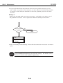
REF.
This manual does not contain complete information required for
disassembling and assembling the BJC-6000 printer. Please also refer to
the separate Parts Catalog.
I
II. TABLE OF CONTENTS
Page
1- 1
1- 1
1- 2
1- 2
1- 3
1- 4
1- 5
1- 5
1- 5
1- 6
1- 6
1- 6
1- 7
1- 7
1- 7
1- 8
1- 8
1- 9
1 -10
1 -11
1 -11
1 -12
1 -13
1 -14
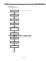
Part 1: SAFETY AND PRECAUTIONS
1. SAFETY PRECAUTIONS
1.1 Moving Parts
1.2 Ink Stains
1.2.1 Ink paths
1.2.2 Ink mist
1.3 Live Electrical Parts
2. MACHINE PRECAUTIONS
2.1 BJ Cartridges
2.1.1 BJ cartridge handling
2.1.2 Automatic capping
2.1.3 When not using the printer
2.1.4 Ink's electroconductivity
2.2 Ink Tanks
2.2.1 Unpacking the ink tank
2.2.2 Ink tank handling
2.3 Printer Handling
2.3.1 Spurs
2.3.2 Damage due to static electricity
2.3.3 Ink leakage prevention
3. NOTES ON SERVICING
3.1 EEPROM Data
3.2 Static Electricity
3.3 Disassembly and Reassembly
3.4 Self Diagnosis
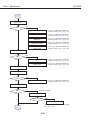
Part 2: PRODUCT SPECIFICATIONS
2- 1
2- 1
2- 2
2- 3
2- 3
2- 3
2- 4
2- 4
2- 5
2- 5
2- 5
2- 6
2- 6
2- 8
2 -10
1. PRODUCT OUTLINE
1.1 Outline
1.2 Features
1.3 BJ Cartridge
1.3.1 Black BJ cartridge
1.3.2 Color BJ cartridge
1.3.3 Photo BJ cartridge
1.4 BJ Cartridge Container
1.5 Consumables
1.5.1 Black, color, and photo BJ cartridges
1.5.2 Ink tanks
2. SPECIFICATIONS
2.1 General Specifications
2.2 Paper Specifications
2.3 Interface Specifications
Part 3: OPERATING INSTRUCTIONS
3333333-
1
1
2
3
3
3
3
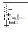
1. PRINTER SETUP
1.1 Unpacking
1.2 Installation Location
1.3 Installation
1.3.1 Connecting the interface cable
1.3.2 Connecting the power cord
1.3.3 Installing the BJ cartridges
II
Page
3- 9
3 -10
3 -11
3 -11
3 -12
3 -12
3 -13
3 -14
3 -14
3 -14
3 -15
3 -15
3 -16
3 -16
3 -16
3 -17
3 -18
3 -18
3 -19
3 -20
3 -21
3 -21
3 -21
1.3.4 Aligning the print heads
1.4 Names of Parts and Their Functions
2. TRANSPORTING THE PRINTER
2.1 Transporting the Printer
3. PRINTER SERVICE FUNCTIONS
3.1 Error Indications
3.2 Description of Error Indications
3.3 BJ Status Monitor
3.3.1 Main functions of the BJ status monitor
3.3.2 Items displayed on the BJ status monitor
3.4 Function Settings
3.4.1 Function settings using the printer driver
3.5 Off-Line Operations
3.5.1 Cleaning
3.5.2 Nozzle check pattern printing
3.5.3 Roller cleaning
3.6 Service Mode
3.6.1 Service mode operations
3.6.2 Service/factory test print
3.6.3 EEPROM information print
3.6.4 Resetting EEPROM
3.6.5 Model setting
3.6.6 Automatic head position adjustment
Part 4: TECHNICAL REFERENCE
4- 1
4- 1
4- 2
4- 3
4- 4
4- 4
4- 6
4- 9
4 -10
4 -10
4 -10
4 -11
4 -12
4 -13
4 -13
4 -13
4 -13
4 -13
4 -15
4 -16
4 -16
4 -16
4 -16
4 -16
4 -17
4 -17
4 -17
4 -17
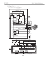
1. OVERVIEW
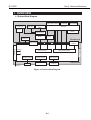
1.1 Printer Block Diagram
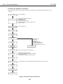
1.2 Power On Sequence Flowchart
1.3 Flow of Print Signals
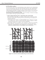
1.4 Print Driving
1.4.1 Print drive control
1.4.2 Print drive method
1.5 Power-Off Sequence Flowchart
2. FIRMWARE
2.1 Interface
2.1.1 Compatible mode
2.1.2 Nibble mode
2.1.3 ECP mode
2.2 Print Control
2.2.1 Print mode
2.2.2 Multi-drop print
2.2.3 Photo-print
2.2.4 Automatic switching control of printing nozzles
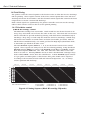
2.3 Automatic Printing Position Alignment Function
2.4 Pause Between Scanning
2.5 Pause Between Pages
2.6 Smear Control
2.7 Auto Power ON/OFF
2.8 Head Overheat Protection
3. PRINTER'S MECHANICAL SYSTEM
3.1 Overview
3.1.1 BJ cartridge unit
3.1.2 Carriage unit
III
Page
4 -18
4 -18
4 -19
4 -19
4 -20
4 -21
4 -25
4 -25
4 -26
4 -28
4 -28
4 -30
4 -32
4 -32
4 -33
4 -36
4 -36
4 -37
4 -37
4 -38
4 -41
4 -41
4 -41
4 -42
4 -42
4 -42
4 -42
4 -42
4 -43
4 -43
4 -43
4 -43
4 -44
4 -44
4 -44
4 -44
3.1.3 Purge unit
3.1.4 Paper feed unit
3.2 BJ Cartridge
3.2.1 Construction of the Black BJ cartridge
3.2.2 Construction of the Color/Photo BJ cartridge
3.2.3 Construction of the bubble jet head unit
3.3 Purge Unit
3.3.1 Function of the purge unit
3.3.2 Construction of the purge unit
3.4 Paper Feed Unit
3.4.1 Functions of the paper feed unit
3.4.2 Construction of the paper feed unit
3.5 Carriage Unit
3.5.1 Functions of carriage unit
3.5.2 Construction of the carriage unit
4 PRINTER'S ELECTRICAL SYSTEM
4.1 Overview
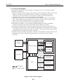
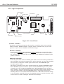
4.2 Control Unit
4.2.1 Control unit block diagram
4.2.2 Logic Components
4.3 Power Supply Unit
4.3.1 Power Supply Unit Block Diagram
4.3.2 Construction of Power Supply Unit
5. DETECTION FUNCTIONS
5.1 Detection with Sensors
5.1.1 Home position sensor
5.1.2 Paper end sensor
5.1.3 Print position sensor
5.1.4 Ink sensor
5.1.5 Cover sensor
5.1.6 Pump sensor
5.1.7 Printer temperature sensor (TH201)
5.1.8 Head temperature sensor
5.2 Other Detection Functions
5.2.1 Waste ink amount detection
5.2.2 BJ cartridge detection
Part 5: MAINTENANCE
55555555555555555-
1
1
1
1
2
2
3
4
4
4
4
5
6
6
7
8
8
1. MAINTENANCE
1.1 Parts for Periodic Replacement
1.2 List of Consumables
1.3 List of Periodic Maintenance
2. SERVICE TOOLS
2.1 List of Tools
3. APPLYING GREASE
4. DISASSEMBLY AND REASSEMBLY
4.1 Disassembly and Reassembly
4.2 Notes on Disassembly and Reassembly
4.2.1 Unlocking the carriage
4.2.2 Removing the printer unit
4.2.3 Removing the ASF unit
4.2.4 Removing the adjustable bearings supporting the carriage shaft
4.2.5 Paper feed gears
5. ADJUSTMENTS AND SETTINGS
5.1 Adjustments and Settings
IV
5- 8
5- 8
5- 8
5- 8
5- 9
5- 9
5- 9
5 -10
5 -11
5 -13
5 -13
5 -13
5 -13
5 -15
5 -15
5 -18
5 -36
5 -36
5 -40
5 -43
5 -44
5 -44
5 -45
5 -45
5 -46
5 -46
5 -46
5 -47
5 -47
5 -47
5 -48
5 -49
5.1.1 EEPROM setting
5.1.2 Carriage belt tension adjustment
5.1.3 ASF gear position adjustment
5.1.4 Head gap adjustment
5.2 Adjustment/Setting Procedures
5.2.1 EEPROM setting
5.2.2 Carriage belt tension adjustment
5.2.3 ASF gear position adjustment
5.2.4 Head gap adjustment
6. TROUBLESHOOTING
6.1 Troubleshooting Overview
6.1.1 Overview
6.1.2 Notes on troubleshooting
6.2 Diagnosis
6.2.1 Initial flowchart
6.2.2 Action
7. CONNECTOR POSITIONS AND PIN ASS
7.1 Control Board
7.2 Carriage Board
7.3 BJ Cartridge
7.4 AC adapter
7.5 DC power supply cable
7.6 Carriage Motor
7.7 Paper Feed Motor
7.8 Ink Sensor
7.9 Print Position Sensor
7.10Pump Sensor
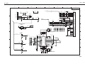
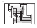
8. CIRCUIT DIAGRAMS
8.1 Parts Layout
8.1.1 Control board
8.1.2 Carriage board
8.2 Circuit Diagrams
V
III. ILLUSTRATION INDEX
Page
1- 1
1- 2
1- 3
1- 4
1- 5
1- 7
1- 7
1- 8
1- 9
1 -10
1 -12
1 -13
Part 1: SAFETY AND PRECAUTIONS
Figure
Figure
Figure
Figure
Figure
Figure
Figure
Figure
Figure
Figure
Figure
Figure
1- 1
1- 2
1- 3
1- 4
1- 5
1- 6
1- 7
1- 8
1- 9
1- 10
1- 11
1- 12
The Printer's Moving Parts
Ink Paths
Ink Mist
Live Electrical Parts
BJ Cartridges
Unpacking the Ink Tank
Installing the Ink Tank
Spurs
Damage Due to Static Electricity
Capping Position
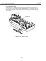
Control Board and Other Electrical Components
How to Disengage a Plastic Hook
Part 2: PRODUCT SPECIFICATIONS
2- 1
2- 3
2- 3
2- 4
2- 4
2- 5
2- 5
2- 9
2 -15
2 -16
2 -16
Figure
Figure
Figure
Figure
Figure
Figure
Figure
Figure
Figure
Figure
Figure
2- 1
2- 2
2- 3
2- 4
2- 5
2- 6
2- 7
2- 8
2- 9
2- 10
2- 11
Printer Appearance
Black BJ Cartridge
Color BJ Cartridge
Photo BJ Cartridge
BJ Cartridge Container
BJ Cartridges
Ink Tanks
Printable Area
Timing Chart (Compatible mode)
Timing Chart (Nibble mode)
Timing Chart (ECP mode)
Part 3: OPERATING INSTRUCTIONS
3- 1
3- 2
3- 3
3- 3
3- 4
3- 5
3- 6
3- 7
3- 8
3- 9
3 -10
3 -12
3 -14
3 -15
3 -17
3 -19
3 -20
Figure
Figure
Figure
Figure
Figure
Figure
Figure
Figure
Figure
Figure
Figure
Figure
Figure
Figure
Figure
Figure
Figure
3- 1
3- 2
3- 3
3- 4
3- 5
3- 6
3- 7
3- 8
3- 9
3- 10
3- 11
3- 12
3- 13
3- 14
3- 15
3- 16
3- 17
Packaging
Printer Dimensions
Connecting the Interface Cable
Connecting the Power Cord
Removing Head Cap and Tape from BJ Cartridge
Installing BJ Cartridges
Installing the Ink Tanks
Replacing an Ink Tank
Cartridge Container
Print Position Adjustment Pattern
Names of Parts and Their Functions
Operator Panel
BJ Status Monitor (Sample)
Printer Driver Utility (Sample)
Nozzle Check Pattern Print (Sample for Black/Color Cartridge)
Service/Factory Test Print
EEPROM Information Print (Sample)
Part 4: TECHNICAL REFERENCE
44444-
1
2
3
4
6
Figure
Figure
Figure
Figure
Figure
44444-
1
2
3
4
5
Printer Block Diagram
Initial Sequence Flowchart
Flow of Print Signals
Printing Sequence (Black BJ cartridge, HQ mode)
Print Drive Method (Multi-drop, forward direction)
VI
Page
4- 7
4- 8
4- 9
4 -10
4 -11
4 -12
4 -15
4 -17
4 -19
4 -20
4 -21
4 -22
4 -22
4 -25
4 -26
4 -27
4 -28
4 -29
4 -30
4 -32
4 -33
4 -34
4 -35
4 -35
4 -36
4 -37
4 -37
4 -38
4 -41
4 -42
4 -43
Figure
Figure
Figure
Figure
Figure
Figure
Figure
Figure
Figure
Figure
Figure
Figure
Figure
Figure
Figure
Figure
Figure
Figure
Figure
Figure
Figure
Figure
Figure
Figure
Figure
Figure
Figure
Figure
Figure
Figure
Figure
4- 6
4- 7
4- 8
4- 9
4- 10
4- 11
4- 12
4- 13
4- 14
4- 15
4- 16
4- 17
4- 18
4- 19
4- 20
4- 21
4- 22
4- 23
4- 24
4- 25
4- 26
4- 27
4- 28
4- 29
4- 30
4- 31
4- 32
4- 33
4- 34
4- 35
4- 36
Print Drive Method (1440 x 720 dpi, forward direction)
Print Drive Method (Reverse direction)
Power-Off Sequence Flowchart
Interfacing Timing (Compatible Mode)
Interface Timing (Nibble Mode)
Interface Timing (ECP mode, reverse transfer)
Automatic Printing Position Alignment
Printer's Mechanical System
Black BJ Cartridge
Color/Photo BJ Cartridge
Bubble Jet Nozzle (part)
Nozzle Arrangement
Signal Contacts
Purge Unit
Purge Unit
Pumping Operations
Paper Feed Path
Paper Thickness Adjustment Mechanism
Paper Feed Unit
Carriage Unit
Carriage Unit
BJ Cartridge Maintenance
Drive Switching Unit
Operation of the Drive Switching Unit
Printer's Electrical System
Control Unit Block Diagram
Control Unit Function Diagram
Control Board
Power Supply Unit Block Diagram
Sensor Positions
Ink Sensor
Part 5: MAINTENANCE
5- 3
5- 4
5- 5
5- 6
5- 6
5- 7
5- 9
5 -10
5 -11
5 -12
5 -36
5 -40
5 -43
5 -44
5 -44
5 -45
5 -45
5 -46
5 -46
5 -46
5 -47
5 -48
Figure
Figure
Figure
Figure
Figure
Figure
Figure
Figure
Figure
Figure
Figure
Figure
Figure
Figure
Figure
Figure
Figure
Figure
Figure
Figure
Figure
Figure
5- 1
5- 2
5- 3
5- 4
5- 5
5- 6
5- 7
5- 8
5- 9
5- 10
5- 11
5- 12
5- 13
5- 14
5- 15
5- 16
5- 17
5- 18
5- 19
5- 20
5- 21
5- 22
Grease Points
Unlocking the Carriage
Removing the Printer Unit
Removing the ASF Unit
Adjustable Bearings Supporting the Carriage Shaft
Feed Gear Unit Precautions
Carriage Belt Tension Adjustment
ASF Gear Position Adjustment
Head Gap Adjustment (1)
Head Gap Adjustment (2)
Control Board
Carriage Board
BJ Cartridge
AC adapter
DC Power Supply Cable
Carriage Motor
Paper Feed Motor
Ink Sensor
Print Position Sensor
Pump Sensor
Control Board
Carriage Board
VII
IV. TABLE INDEX
Page
3 -12
Part 3: OPERATING INSTRUCTIONS
Table
3- 1
Error Indications
Part 4: TECHNICAL REFERENCE
4 -14
4 -23
Table
Table
4- 1
4- 2
Print Mode List
Signal Contacts
VIII
Part 1
SAFETY AND
PRECAUTIONS
Page
1- 1
1- 1
1- 2
1- 4
1- 5
1- 5
1- 7
1- 8
1 -11
1 -11
1 -12
1 -13
1 -14
1. SAFETY PRECAUTIONS
1.1 Moving Parts
1.2 Ink Stains
1.3 Live Electrical Parts
2. MACHINE PRECAUTIONS
2.1 BJ Cartridges
2.2 Ink Tanks
2.3 Printer Handling
3. NOTES ON SERVICING
3.1 EEPROM Data
3.2 Static Electricity
3.3 Disassembly and Reassembly
3.4 Self Diagnosis
Part 1: Safety and Precautions
BJC-6000
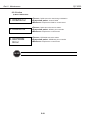
1. SAFETY PRECAUTIONS
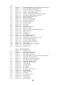
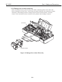
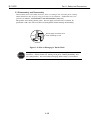
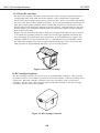
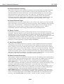
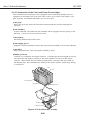
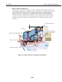
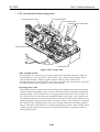
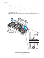
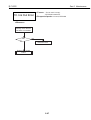
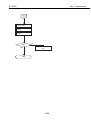
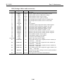
1.1 Moving Parts
Be careful not to get your fingers, hair, clothing, or accessories caught in the moving
parts of the printer.
The moving parts are driven either by the carriage motor or paper feed motor. The
carriage motor-related moving parts include the carriage, carriage belt, and carriage
ribbon-cable. The paper feed motor-related moving parts include the paper feed gears,
paper feed rollers, pinch rollers, eject roller gears, spurs, and pick-up rollers.
To prevent injuries, the printer will stop after moving the carriage to the cartridge
replacement position if the cover is opened.
Pick-up Roller
Carriage Ribbon Cable
Pressure Roller
Idler Pulley
Paper Feed Gear
Eject Roller Gear
Paper Feed Roller
Carriage Belt
Carriage Motor
Spur
Figure 1-1 The Printer's Moving Parts
1-1
Part 1: Safety and Precautions
BJC-6000
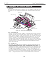
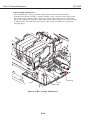
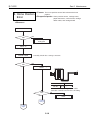
1.2 Ink Stains
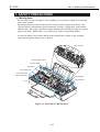
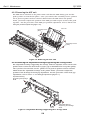
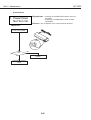
1.2.1 Ink paths
Be careful not to touch the ink paths. Ink on hands could stain the printer, work
table, or clothes. The ink paths include the BJ cartridge ink tank outlet, the BJ
cartridge ink filters and nozzles, the maintenance jet receiving section, the head caps,
the wipers, and the waste ink absorber.
CAUTION
The ink is not harmful to the human body, but contains some organic
solvents:
The black ink contains glycerin 56-81-5 and diethylene glycol 111-46-6.
The yellow ink contains glycerin 56-81-5 and isopropyl alcohol 67-63-0.
The cyan, magenta, photo-cyan, photo-magenta and photo-black ink
contain glycerin 56-81-5, isopropyl alcohol 67-63-0, ethylene glycol 10721-1, and diethylene glycol 111-46-6.
Be careful not to get the ink into your mouth or eyes. If the ink gets into
your eyes, wash with plenty of water and consult a doctor. In case you
have swallowed a large amount of ink, consult a doctor immediately.
The ink contains dyes. If clothing is stained with the ink, the ink may not
be removed completely.
Maintenance
Jet Receiving
Section
BJ Cartridges
Wiper
Waste Ink Absorber
Figure 1-2 Ink Paths
1-2
Head Cap
Part 1: Safety and Precautions
BJC-6000
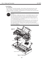
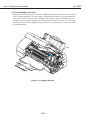
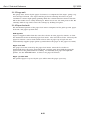
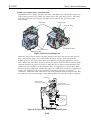
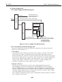
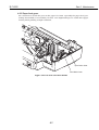
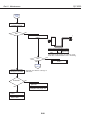
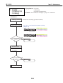
1.2.2 Ink mist
The BJ cartridge ejects ink onto the paper during printing. After the printer is used
for a long period or used heavily, part of the ink ejected from the nozzles, or ink mist
bouncing back from the paper could accumulate and contaminate the platen, front
cover, as well as the periphery of the purge unit. Carefully wipe off the ink mist with
a dampened soft cloth so that hands or clothing will not be stained by contaminated
parts during servicing.
Front Cover
Platen
Figure 1-3 Ink Mist
1-3
Part 1: Safety and Precautions
BJC-6000
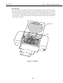
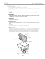
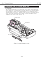
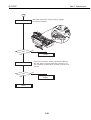
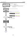
1.3 Live Electrical Parts
When the printer is plugged into a wall outlet, the power supply unit of the printer is
live, even if the power is switched off with the POWER button. Be careful not to get an
electric shock or damage sensitive elements if you are checking a live printer with the
cover removed.
Control Board
Figure 1-4 Live Electrical Parts
1-4
Part 1: Safety and Precautions
BJC-6000
2. MACHINE PRECAUTIONS
2.1 BJ Cartridges
2.1.1 BJ cartridge handling
Do not unpack the BJ cartridge until you are ready to use it. Before installing the BJ
cartridge in the printer, carefully remove the head cap which protects the nozzles, the
protective tape, and the protective tank. To prevent the nozzles or other ink paths
from clogging, never touch or wipe the nozzles or other ink outlets with your bare
hands or tissue paper. After removing the head cap, the protective tape, and the
protective tank from a BJ cartridge, promptly install the cartridge in the printer or
store it in the cartridge container. Do not reuse head caps or protective tapes which
have been removed. The BJ cartridge must be installed in the printer or stored in the
cartridge container with its ink tanks installed. If the BJ cartridge is installed or
stored with its ink tanks removed, the nozzles could clog due to foreign matter or
dried ink. Do not attempt to disassemble or wash the BJ cartridge.
NOTE
If a nozzle clogs, or ink fails to be fed normally, print quality degrades, and
typically a fine horizontal blank line appears in printed images. If cleaning
operations do not solve the problem, replace the BJ cartridge with a new
one.
Protective Tape
Head Cap
Figure 1-5 BJ Cartridges
1-5
Part 1: Safety and Precautions
BJC-6000
2.1.2 Automatic capping
When the printer is turned off with the POWER button, it automatically caps the BJ
cartridge's nozzles to protect them as well as to prevent ink leakage. If the AC cable is
unplugged from a wall outlet before the printer is turned off with the POWER button,
the nozzles will not be automatically capped. In this case, plug in the AC cable again,
turn on the printer, and then turn it off with the POWER button. The nozzles will be
automatically capped.
CAUTION
If the nozzles are not capped, ink may dry out and clog the nozzles or leak
from the cartridge.
2.1.3 When not using the printer
The BJ cartridge may be either left installed in the printer or stored in the cartridge
container. This also applies when carrying, transporting, or storing the printer.
CAUTION
If the BJ cartridge is left in open air, out of the printer or cartridge
container, foreign matter or dried ink may clog the nozzles, resulting in
poor print quality.
2.1.4 Ink's electroconductivity
The ink in the BJ cartridge conducts electricity. If ink is spilt in the printer's
mechanical parts, use a dampened paper towel to wipe clean. If ink is spilt onto the
printer's electrical components, use tissue paper to wipe clean. If ink gets under an
IC chip on the control board and cannot be removed thoroughly, replace the control
board with a new one.
CAUTION
Never plug in the printer if its' electric circuitry is in contact with spilt ink.
Otherwise the electric circuitry could be damaged.
1-6
Part 1: Safety and Precautions
BJC-6000
2.2 Ink Tanks
2.2.1 Unpacking the ink tank
Do not unpack the ink tank until you are ready to use it. When installing it in the BJ
cartridge, unpack the ink tank, peel off the vinyl lamination, and remove the cap from
the ink outlets.
Figure 1-6 Unpacking the Ink Tank
2.2.2 Ink tank handling
If the joint of the BJ cartridge connecting to the ink tank supply piece is contaminated,
suction of ink into the BJ cartridge could fail. Therefore, never touch the ink tank's
ink supply piece. After removing the cap from the ink tank supply piece, promptly
install the ink tank in the BJ cartridge to prevent the nozzles from clogging due to dried-ink.
Do not remove the ink tank from the BJ cartridge unless you are replacing it.
Figure 1-7 Installing the Ink Tank
NOTE
If a nozzle clogs, or otherwise ink fails to be fed normally, print quality
degrades, and typically a fine horizontal blank line appears in printed
images. If cleaning operations do not solve the problem, replace the BJ
cartridge with a new one.
1-7
Part 1: Safety and Precautions
BJC-6000
2.3 Printer Handling
2.3.1 Spurs
Take care not to bend the tips of the spurs. The tips of the spurs make contact with
printed paper and are contaminated with ink, but due to their small surface contact
area, the tips, cleaned by the spur cleaners, will not stain the printed paper.
However, if the tips are bent and their surface contact area increases, they collect
more ink and are not easily cleaned by the spur cleaners, and thereby stain the
printed paper by making dotted lines on it.
Spurs
Figure 1-8 Spurs
1-8
Part 1: Safety and Precautions
BJC-6000
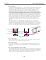
2.3.2 Damage due to static electricity
Static electricity may be generated by your clothes rubbing against each other and
may accumulate in your body. If you touch electrical elements, the discharge of static
electricity could damage them or change their electrical characteristics. For this
reason, never touch the sensor contacts or the printer's BJ cartridge contacts.
Ink Sensor
Contact
Points
Contact Points
Figure 1-9 Damage Due to Static Electricity
1-9
Part 1: Safety and Precautions
BJC-6000
2.3.3 Ink leakage prevention
When you turn off the printer using the POWER button, the printer moves the carriage
to the capping position, caps the nozzles, and locks the carriage in position with the
lock arm. If electric power is not available to the printer, during transportation for
example, this automatic capping and locking is not available. In this case, manually
move the carriage to the capping position and secure it with tape to ready the printer
for transportation.
Tape
Figure 1-10 Capping Position
1-10
Part 1: Safety and Precautions
BJC-6000
3. NOTES ON SERVICING
3.1 EEPROM Data
The printer keeps track of the total sheets printed by each BJ cartridge configuration
(Black/Color and Photo/Color) and the total waste ink amount and stores that
information in the EEPROM (IC 602) on the logic board. Observe the following
precautions during servicing:
1) Before servicing
You can check the EEPROM data with a test print. The total sheets printed by each
configuration can provide important information on how much the printer has been
used.
2) If the control board (EEPROM) is replaced (or if stored data is cleared by
mistake)
Check the waste ink absorber, and replace it with a new one if necessary. If you fail
to replace the waste ink absorber in time, the waste ink full alarm might not be
issued in time and waste ink could leak (depending on the current ink absorbing
capacity of the waste ink absorber). When replacing the logic board (EEPROM) with
a new one, be sure to clear the data on the new EEPROM, because the data is not
defined.
3) After the waste ink absorber is replaced
After replacing the waste ink absorber, as prompted by the waste ink full alarm,
clear the data on the EEPROM.
CAUTION
REF.
Once cleared, the EEPROM data cannot be restored (cannot be checked
with a test print). Always check the EEPROM data with a test print before
clearing it. The data includes information on the user settings, the total
sheets of printed paper and the total amount of waste ink absorbed. Note
that you cannot edit the data from the operator panel.
The printer calculates the total amount of waste ink absorbed based on
the estimated usage of the printer. To prevent the capacity of the waste
ink absorber from being exceeded, the waste ink full alarm is issued when
the waste ink absorber gets full, suspending the operation of the printer.
Refer to Part 3: 3.6.4 Resetting EEPROM (Page 3-21) for the procedures for
checking the EEPROM data with a test print or for clearing the data.
Refer to Part 5: 6. TROUBLESHOOTING (Page 5-13) for the troubleshooting
procedures to be followed when the waste ink full alarm is issued.
1-11
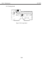
Part 1: Safety and Precautions
BJC-6000
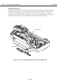
3.2 Static Electricity
Static electricity may be generated by your clothes rubbing against each other and may
accumulate in your body. If you touch electrical elements, the discharge of the static
electricity could damage them or change their electrical characteristics. To prevent
damage due to such electrostatic discharge, ground yourself by touching a metal fitting
which is grounded before disassembling or otherwise servicing the printer.
Control Board
AC Adapter
Figure 1-11 Control Board and Other Electrical Components
1-12
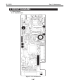
Part 1: Safety and Precautions
BJC-6000
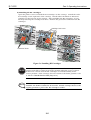
3.3 Disassembly and Reassembly
Disassembly and reassembly must be done according to the relevant parts catalog,
which illustrates the step-by-step procedures to be followed. Additional notes are
provided in Part5: 4. DISASSEMBLY AND REASSEMBLY (Page 5-4).
The printer uses many plastic parts. Do not apply excessive force to them. In
particular, take care not to break or deform plastic hooks during disassembly.
Hook
Never apply excessive force
when releasing a hook.
Figure 1-12 How to Disengage a Plastic Hook
CAUTION
Some plastic parts contain glass fibers to conform to tight dimensional
tolerances. Plastic hooks are among such parts, lacking flexibility, and
are easily broken. Do not forcibly disengage them using a screwdriver.
1-13
Part 1: Safety and Precautions
BJC-6000
3.4 Self Diagnosis
The printer has self-diagnosis features to detect hardware defects. The results of the
diagnosis are indicated by the indicator and power lamp (flashing) on the operator panel as
well as by the buzzer. For details, refer to Part 3: 3.1 Error Indications (Page 3-12).
1-14
Part 2
PRODUCT
SPECIFICATIONS
Page
2- 1
2- 1
2- 2
2- 3
2- 4
2- 5
2- 6
2- 6
2- 8
2 -10
1. PRODUCT OUTLINE
1.1 Outline
1.2 Features
1.3 BJ Cartridge
1.4 BJ Cartridge Container
1.5 Consumables
2. SPECIFICATIONS
2.1 General Specifications
2.2 Paper Specifications
2.3 Interface Specifications
Part 2: Product Specifications
BJC-6000
1. PRODUCT OUTLINE
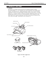
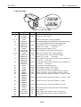
1.1 Outline
This printer is a desktop business/personal color bubble-jet printer for high
speed/high quality use. It accommodates two "drop-modulation" BJ cartridges on its
carriage. For high speed use, a pigment-Black BJ cartridge and a Color BJ cartridge
combination achieves four-color printing for quality equal to a laser printer. For high
quality use, a Color BJ cartridge and Photo BJ cartridge combination achieves six-color
printing whose quality is as good as a color photograph. The BJ cartridges use ink
tanks which can be replaced individually, and whose tank material is translucent for
easier ink level checking, contributing to lower running cost.
Operator Panel
Paper Support
Paper Guide
Auto Sheet Feeder
Front Cover
Paper Output Tray
Parallel Interface Connector
Paper Thickness Lever
Cartridge Container
Manual Feed Slot
BJ Cartridges
Figure 2-1 Printer Appearance
2-1
Part 2: Product Specifications
BJC-6000
1.2 Features
· Laser-printer quality using pigment black ink
· Dual-cartridge system
High quality printing at high speed from a combination of the Black and Color
cartridges or the Color and Photo cartridges
Black BJ cartridge: Drop modulation, replaceable ink tank (pigment black), 160 nozzle
head
Color BJ cartridge: Drop modulation, individually replaceable ink tanks (yellow,
magenta and cyan), 144 in-line nozzle head (48 nozzles for each of
three colors)
Photo BJ cartridge: Drop modulation, individually replaceable ink tanks (dye black,
photo-magenta and photo-cyan), 144 in-line nozzle head (48
nozzles for each of three colors)
· Individually replaceable ink tanks for high cost performance
Black ink tanks: Pigment black ink tank
Color ink tanks: Yellow, magenta, and cyan ink tanks
Photo ink tanks: Dye black, magenta, and cyan ink tanks
· Ink-out detection, and translucent ink tanks for easier ink level checking
· High speed printing (8.0 PPM black printing or 5.0 PPM color printing in HS mode)
· 1440 x 720 dpi high resolution printing
· Automatic printing position adjustment
Ensures accurate printing position regardless of cartridges being used or carriage
movement direction
· Supports a wide variety of print media
· Up to A4/Letter full-bleed size paper and banner paper can be used
· Blue Angel compliant
2-2
Part 2: Product Specifications
BJC-6000
1.3 BJ Cartridge
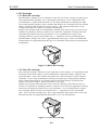
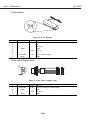
1.3.1 Black BJ cartridge
The Black BJ cartridge is to be mounted on the left side of the carriage for high speed
color/monochrome printing. It is a disposable print head. It has 160 nozzles and
accommodates a replaceable ink tank. It uses drop modulation technology for high
speed, high quality printing, where smaller ink-droplets are discharged for low density
images and larger ink-droplets for denser images. The pigment black ink is water
resistant and allows for dense and sharp text printing.
Replace the ink tank and/or the Black BJ cartridge if the ink-out error is issued or if
satisfactory printing cannot be achieved even after the stipulated cleaning and head
refreshing operations have been performed. It is recommended to replace any
cartridge which is at least six months old, i.e., unpacked at least six months prior.
The Black BJ cartridge has a life of approximately 5000 pages, and a new black ink
tank provides for approximately 500 pages of a standard 1500 character print pattern
in HQ mode.
Figure 2-2 Black BJ Cartridge
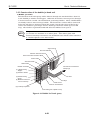
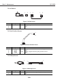
1.3.2 Color BJ cartridge
The Color BJ cartridge, mounted on the right side of the carriage, is a disposable print
head with 144 in-line nozzles, and accommodates replaceable yellow, magenta and
cyan ink tanks. It has 144 nozzles (48 nozzles for each of the three colors), aligned
vertically. It uses drop modulation technology for high speed, high quality printing,
where smaller ink-droplets are discharged for low density images and larger inkdroplets for denser images. Each color ink is a dye-type.
Replace the relevant ink tank and/or the Color BJ cartridge if the ink-out error is
issued or if satisfactory printing cannot be achieved even after the stipulated cleaning
and head refreshing operations have been performed. It is recommended to replace
any cartridge which is at least six months old, i.e., unpacked at least six months
prior. The Color BJ cartridge has a life of approximately 3000 pages and a new color
ink tank provides for approximately 280 pages of a 7.5% duty pattern.
Figure 2-3 Color BJ Cartridge
2-3
Part 2: Product Specifications
BJC-6000
1.3.3 Photo BJ cartridge
The Photo BJ cartridge, mounted on the left side of the carriage for photo printing, is
a disposable print head with 144 in-line nozzles, and accommodates replaceable
photo-black, photo-magenta and photo-cyan ink tanks. It has 144 nozzles (48 nozzles
for each of the three colors), aligned vertically. It uses drop modulation technology for
high speed, high quality printing, where smaller ink-droplets are discharged for low
density images and larger ink-droplets for denser images. The black ink is a dye-type
and the photo-cyan and photo-magenta inks are three times lighter in color density
than normal color inks.
Replace the relevant ink tank and/or Photo BJ cartridge if the ink-out error is issued
or if satisfactory printing cannot be achieved even after the stipulated cleaning and
head refreshing operations have been performed. It is recommended to replace any
cartridge which is at least six months old, i.e., unpacked at least six months earlier.
The Photo BJ cartridge has a life of approximately 3000 pages and a new color ink
tank provides for approximately 280 pages of a 7.5% duty pattern.
Figure 2-4 Photo BJ Cartridge
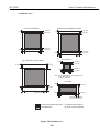
1.4 BJ Cartridge Container
The BJ cartridge container is used to store non-installed BJ cartridges. The lid of the
container must be closed fully to prevent the ink in the nozzles of the BJ cartridge from
drying out. Each BJ cartridge container can store one Black, Color, or Photo BJ
cartridge. Always store a BJ cartridge with its ink tanks installed. The BJ cartridge
containers can be connected together.
Figure 2-5 BJ Cartridge Container
2-4
Part 2: Product Specifications
BJC-6000
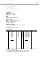
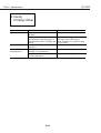
1.5 Consumables
1.5.1 Black, color, and photo BJ cartridges
The Black, Color and Photo BJ cartridges for this printer are consumables. The BJ
cartridges that come with your printer are identical to the BJ cartridges that are
commercially available as consumables, except for the packaging.
Figure 2-6 BJ Cartridges
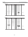
1.5.2 Ink tanks
The consumable ink tanks include the black ink tanks for the Black BJ cartridge;
yellow, magenta and cyan ink tanks for the Color BJ cartridge; and photo-black,
photo-magenta and photo-cyan ink tanks for the Photo BJ cartridge. The ink tanks
are usable for six months after they are unpacked.
A black ink tank provides for approximately 500 pages of a standard 1500-character
text pattern in HQ mode.
A color ink tank provides for approximately 280 pages of a 7.5% duty pattern in HQ
mode.
A photo-color ink tank provides for approximately 280 pages of a 7.5% duty pattern in
HQ mode.
Cyan Ink Tank
Black Ink Tank
Magenta Ink Tank
Yellow Ink Tank
Photo-black Ink Tank
Photo-magenta Ink Tank
Photo-cyan Ink Tank
Figure 2-7 Ink Tanks
2-5
Part 2: Product Specifications
BJC-6000
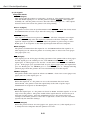
2. SPECIFICATIONS
2.1 General Specifications
1. Type
Desktop serial color bubble-jet printer
2. Paper feeding method
Automatic sheet feeder and manual sheet feed
3. Automatic sheet feeder capacity
Plain paper:
13 mm max. stacking height (about 130 sheets of 64
g/m2 paper)
High-resolution paper:
10 mm max. stacking height (about 100 sheets of 64
g/m2 paper)
Envelopes (fed longitudinally): 15 envelopes max. (max. 13mm stacking height)
Transparencies:
30 sheets max.
Back print film:
10 sheets max.
Government postcard:
40 sheets max.
Glossy photo paper:
10 sheets max.
Gloss photo film:
1 sheet
Fabric sheets:
1 sheet
T-shirts transfer:
1 sheet
4. Printing speed
Black printing:
Color printing:
Photo printing:
5. Printing direction
HS mode:
HQ mode:
Fine mode:
788 cps in high speed mode,
567 cps in standard speed mode
About 1.6 ppm in high speed mode,
1.2 ppm in standard speed mode
0.18 ppm in high quality mode
Bi-directional
Bi-directional for 360 x 360 dpi.
Uni-directional for 720 x 720 dpi
Uni-directional
6. Printing width
218 mm max.
7. Line feed speed
Approx. 118 ms
8. Internal print control mode
Canon extended mode (available when the Canon printer driver is used), no emulation
mode available
9. Printable characters (for test printing)
Font:
Courier
Character set:
Code page 850
10. Buffer size
128 KB
11. Interface
IEEE 1284-compatible 8-bit parallel (ECP)
2-6
Part 2: Product Specifications
BJC-6000
12. BJ cartridges
Black BJ cartridge
Construction:
Print head:
Ink:
Cartridge service life:
Ink tank:
Ink tank service life:
Cartridge weight:
Separate ink tank type
160 nozzles, in-line
Pigment black
Approx. 5000 pages (1500-character, HQ mode)
Black
Approx. 500 pages (1500-character, HQ mode)
Approx. 60 g (without ink tank)
Color BJ cartridge
Construction:
Print head:
Inks:
Cartridge service life:
Ink tanks:
Ink tank service life:
Cartridge weight:
Separate ink tank type
144 nozzles, in-line (48 nozzles x 3)
Cyan, magenta and yellow
Approx. 3000 pages (7.5% duty, HQ mode)
Yellow, magenta and cyan
Approx. 280 pages (7.5% duty, HQ mode)
Approx. 60 g (without ink tanks)
Photo BJ cartridge
Construction:
Print head:
Inks:
Cartridge service life:
Ink tanks:
Ink tank service life:
Cartridge weight:
Separate ink tank type
144 nozzles in line (48 nozzles x 3)
Photo-black, photo-cyan and photo-magenta
Approx. 3000 pages (7.5% duty, HQ mode)
Photo-black, photo-cyan and photo-magenta
Approx. 280 pages (7.5% duty, HQ mode)
Approx. 60 g (without ink tanks)
13. Detection functions
Cover open:
BJ cartridge installed:
Print position detection:
BJ cartridge identification:
Paper detection:
Ink-out :
Waste ink amount:
Paper width detection:
Yes
Yes
Yes
Yes
Yes
Yes
Yes
No
14. Acoustic noise during operation
Approx. 48 dB (A) or lower/ (HQ/HS mode)
(Sound pressure level: compliant with ISO9296)
15. Environmental conditions
5 to 35°C (41 to 95° F), 10 to 90% RH (no condensation)
Operating:
Storage:
0 to 35°C (32 to 95° F), 5 to 95% RH (no condensation)
16. Power consumption
100-120 Vac, 50/60 Hz, approx. 35 W max., approx. 4 W max. in standby mode
17. External dimensions
475 (W) x 280 (D) x 200 (H) mm
18. Weight
5.9 kg, including BJ cartridges
2-7
Part 2: Product Specifications
BJC-6000
2.2 Paper Specifications
1. Paper sizes
A5 (148 x 210 mm)
A4 (210 x 297 mm)
A4+ (223 x 356 mm)
B5 (182 x 257 mm)
Letter (216 x 279 mm)
Letter+ (229 x 338 mm)
Legal (216 x 356 mm)
Government postcard (100 x 148 mm)
Envelope
Commercial number 10 envelope (9.5" x 4.1")
European DL-size (220 x 110 mm)
Banner paper (203 x 1673 mm to 203 x 1779 mm)
Free (100 x 100 mm to 216 x 584 mm)
2. Paper types
Plain paper
Weight: 64 to 105 g/m2 for auto sheet feeder, 64 to 500 g/m2 for manual feed
Thickness: max. 0.6 mm thick, max. 297 mm long
Government Postcard
weight: max. 190 g/m2, max. 0.23 mm thick
Canon BJ printer High-resolution paper
Glossy photo paper
Glossy photo film
Transparencies
Back print film
Banner paper (long type)
Note: Fan-fold paper or label paper cannot be used.
2-8
Part 2: Product Specifications
BJC-6000
3. Printable Area
Letter (LTR) and legal (LGL) sizes
A4, A5, and B5 sizes
(1) 18.5mm
(2) 26.5mm
3mm
(1) 18.5mm
(2) 26.5mm
3mm
(2) 27.0mm
(1) 22.5mm
7.0mm
3.4mm
3.4mm
(2) 27.0mm
(1) 22.5mm
7.0mm
6.4mm
6.3mm
Postcard size
A4+ and letter+ (LTR+) sizes
(1) 12.0mm
3.0mm
(2) 21.0mm
28.0mm
29.2mm
l
(1) 22.6mm
7.0mm
(2) 21.6mm
3.4mm
3.4mm
Note: The printable area for thick paper is equa
to that for postcards.
Envelope
3.0mm
21.0mm
29.2mm
5.1mm
A4+ 5.9mm
Letter+ 5.1mm
7.0mm
22.6mm
6.4mm
Com #10: 31.4 mm
DL-size: 10.4 mm
: Recommended printing area
: Printable area
Figure 2-8 Printable Area
2-9
(1) Monochrome printing
(2) Color or photo printing
Part 2: Product Specifications
BJC-6000
2.3 Interface Specifications
1) Interface type
IEEE1284-compatible parallel interface
2) Data transfer method
8-bit parallel (supporting nibble/ECP mode)
3) Signal level
Low level: +0.0 to +0.8 V
High level: +2.4 to +5.0 V
4) I/O
Each signal pulled up with +5 V.
5) Interface cable
Type:
Shielded twisted-pair cable
Wire size: AWG 28 or larger
Length: 2.0 m max.
6) Interface connectors
Printer connector: Amphenol 57-40360 or equivalent
Cable connector: Amphenol 57-30360 or equivalent
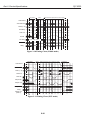
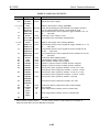
7) I/O signals and pin assignment
Compatible mode
No.
Signal
I/O
No.
Signal
1
STROBE
IN
19
STROBE-RET*1
2
DATA1
IN
20
DATA1-RET
3
DATA2
IN
21
DATA2-RET
4
DATA3
IN
22
DATA3-RET
5
DATA4
IN
23
DATA4-RET
6
DATA5
IN
24
DATA5-RET
7
DATA6
IN
25
DATA6-RET
8
DATA7
IN
26
DATA7-RET
9
DATA8
IN
27
DATA8-RET
10
ACKNLG
OUT
28
ACKNLG-RET
11
BUSY
OUT
29
BUSY-RET
12
P.E.
OUT
30
P.E.-RET
13
SELECT
OUT
31
INIT
14
AUTO FEED XT*4
IN
32
ERROR
15
N.C*2
...
33
GND
16
INIT
IN
34
N.C.*2
17
GND
...
35
+5.0V*3
18
+5.0V*4
...
36
SELECT IN
*1: All RETs are connected to GND.
*2: N.C. means no connection.
*3: The level is pulled up with +5.0 V through a 3.3 k resistor.
*4: The level is pulled up with +5.0 V through a 390 resistor.
2-10
I/O
...
...
...
...
...
...
...
...
...
...
...
...
IN
OUT
...
...
...
IN
Part 2: Product Specifications
BJC-6000
Nibble mode
No.
Signal
I/O
1
HostClk
IN
2
Data1
IN/OUT
3
Data2
IN/OUT
4
Data3
IN/OUT
5
Data4
IN/OUT
6
Data5
IN/OUT
7
Data6
IN/OUT
8
Data7
IN/OUT
9
Data8
IN/OUT
10
PtrClk
OUT
11
PtrBusy
OUT
12
AckDataReq
OUT
13
Xflag
OUT
14
HostBusy
IN
1
15
N.C.*
...
16
Gnd
...
17
Gnd
...
18
Vcc
...
*1: N.C. means no connection.
No.
19
20
21
22
23
24
25
26
27
28
29
30
31
32
33
34
35
36
Signal
Signal Gnd
Signal Gnd
Signal Gnd
Signal Gnd
Signal Gnd
Signal Gnd
Signal Gnd
Signal Gnd
Signal Gnd
Signal Gnd
Signal Gnd
Signal Gnd
INIT
DataAvail
N.C.*1
N.C.*1
N.C.*1
1284Active
I/O
...
...
...
...
...
...
...
...
...
...
...
...
IN
OUT
...
...
...
IN
ECP mode
No.
Signal
I/O
1
HostClk
IN
2
Data1
IN/OUT
3
Data2
IN/OUT
4
Data3
IN/OUT
5
Data4
IN/OUT
6
Data5
IN/OUT
7
Data6
IN/OUT
8
Data7
IN/OUT
9
Data8
IN/OUT
10
PeriphClk
OUT
11
PeriphAck
OUT
12
AckReverse
OUT
13
Xflag
OUT
14
HostAck
IN
...
15
N.C.*1
16
Gnd
...
17
Gnd
...
18
Vcc
...
*1: N.C. means no connection.
No.
19
20
21
22
23
24
25
26
27
28
29
30
31
32
33
34
35
36
Signal
Signal Gnd
Signal Gnd
Signal Gnd
Signal Gnd
Signal Gnd
Signal Gnd
Signal Gnd
Signal Gnd
Signal Gnd
Signal Gnd
Signal Gnd
Signal Gnd
ReverceReq
PeriphReq
N.C.*1
N.C.*1
N.C.*1
1284Active
I/O
...
...
...
...
...
...
...
...
...
...
...
...
IN
OUT
...
...
...
IN
2-11
Part 2: Product Specifications
BJC-6000
8) I/O signals
Compatible Mode:
STROBE (Input)
This signal asks the printer to read Data 1 to Data 8. This signal becomes valid
after the BUSY signal goes "L" and the printer outputs ACKNLG. This signal is
normally "H," and the printer receives data after this signal goes "L." This signal
must be turned "H" before the printer can start printing.
Data 1-8 (Input)
The printer receives data in synchronization with STROBE. Each bit of data must
be maintained for at least 0.5 µs after the rising edge of STROBE.
ACKNLG (Output)
This signal is returned in response to STROBE. The host computer can output
another STROBE only after this signal is returned to the host computer. This
signal is output regardless of STROBE when the printer is powered up or when
BUSY goes "L" in response to the INIT signal input from the host computer.
BUSY (Output)
The printer is BUSY when this signal is "H," and READY when this signal is "L."
This signal goes "H" when the printer is receiving data or detects an error (paper
out, paper jam, etc.).
P.E. (Output)
This signal goes "H" if the paper feeding operation of the printer fails to feed paper.
As this signal goes "H," BUSY goes "H," and SELECT and ERROR go "L." This
signal goes "L" when paper is set and fed. At this time both ERROR and SELECT
go "H." If the paper eject operation fails to eject paper (paper jam), this signal also
goes "H," BUSY goes "H," SELECT goes "L," and ERROR goes "L." Simply removing
jammed paper from the printer does not automatically reset this signal.
SELECT (Output)
The printer makes this signal "H" when it is READY. If an error occurs (paper out,
paper jam, etc.), this signal goes "L."
AUTO FEED XT (Input)
When this signal is "L," the printer is set to the automatic line feed mode
(CR=CR+LF). The printer reads this signal only at the time of power-up or
initialization in response to the INIT signal.
INIT (Input)
When this signal goes "L," the printer is forced to BUSY, and this signal's "L"-to-"H"
edge resets the printer. The pulse width of this signal must be at least 50 µs as
measured at the printer. After the initializing process, the printer moves its
carriage to the home position, enters the 10 cpi mode, and is set in the condition
specified by the function settings.
ERROR (Output)
When the printer detects an error (paper out, paper jam, etc.), this signal goes "L"
to notify the host computer that the printer is in error.
2-12
Part 2: Product Specifications
BJC-6000
SELECT IN (Input)
When this signal is "H," the DC1/DC3 code is enabled; and when this signal is "L,"
the DC1/DC3 code is disabled. The printer reads this signal only at the time of
power-up or initialization in response to the INIT signal.
Nibble Mode:
Host Clk (Input)
This is a STROBE signal for reading Data 1-8. During negotiation, this is the
trigger signal for sending the protocol confirmation to the printer.
Data 1-8 (Input)
The printer receives data in synchronization with Host Clk. Each bit of data must
be maintained for at least 0.5 µs after the rising edge of Host Clk.
Ptr Clk (Output)
In the reverse data transmission phase, the printer asks the host computer to read
data it has sent by making this signal "L." When the host computer has read the
data, it acknowledges the receipt of the data by making Host Busy "H."
Ptr Busy (Output)
In the reverse data transmission phase, this signal serves as bit 3 and bit 7 of data
to be sent.
Ack Data Req (Output)
In the reverse data transmission phase, this signal serves as bit 2 and bit 6 of data
to be sent. During negotiation, this is the trigger signal for notifying the host
computer of the printer's mode settings (whether nibble mode is supported, reverse
transmission data is available, etc.).
Xflag (Output)
In the reverse data transmission phase, this signal serves as bit 1 and bit 5 of data
to be sent. During negotiation, this signal tells the host computer whether or not
the printer supports the nibble mode. When the printer supports the nibble mode,
it makes this signal "L" in synchronization with the rising edge of Ack Data Req.
Host Busy (Input)
In the reverse data transmission phase, the host computer tells the printer that it
has already received data by making this signal "L." When the Ptr Clk signal in the
received data goes "L," this signal goes "L" in response. In the reverse transmission
idle phase, when Ptr Clk goes "L," this signal goes "H" in response, returning to the
reverse data transmission phase.
INIT (Input)
When this signal goes "L," the printer is forced to BUSY, and this signal's "L"-to-"H"
edge resets the printer. This signal is normally "H," and the pulse width of this
signal must be at least 50 µs as measured at the printer.
2-13
Part 2: Product Specifications
BJC-6000
Data Avail (Output)
In the reverse data transmission phase, this signal serves as bit 0 and bit 4 of data
to be sent. During negotiation, this signal tells the host computer whether or not
reverse transmission data is available. This signal is output in synchronization
with the "H"-to-"L" falling edge of Ack Data Req, which defines the timing for
notifying the availability of reverse transmission data.
1284 Active (Input)
This signal is used to confirm if the printer is 1284-compatible. Check is done
when this signal is "H" and Host Busy is "L." This signal goes "L" in the
termination phase.
ECP Mode:
Host Clk (Input)
When data is sent from the host computer to the printer, this signal and Periph
Ack perform handshaking. The host computer makes this signal "L" to notify that
it has output data onto the data bus (Data 1-8). This signal goes "H" in response to
the rising edge of Periph Ack. This signal is always "H" in the reverse data
transmission phase.
Data 1-8 (Input/Output)
These signals are input signals when data is sent from the host computer to the
printer. In the reverse data transmission phase, these signals are output signals
send data from the printer to the host computer over this data bus.
Periph Clk (Output)
This signal is always "H" when data is sent from the host computer to the printer.
In the reverse data transmission phase, this signal goes "L" to notify that data has
been output to the host computer. This signal goes "H" in response to the "L"-to"H" rising edge of Host Ack from the host computer.
Periph Ack (Output)
When data is to be sent from the host computer to the printer, the printer makes
this signal "L" if it is ready to receive data. The printer makes this signal "H" after
it has received the data. In the reverse data transmission phase, this signal is
used to tell whether the data the printer has output on the data bus is command
or data ("L" means command and "H," data).
Ack Reverse (Output)
This signal is always "H" when data is sent from the host computer to the printer.
In the reverse data transmission phase, this signal is always "L." When the host
computer notifies the printer that the forward data transmission phase is to
change to the reverse data transmission phase by making Reverse Req "L," the
printer acknowledges the notification by making this signal "L." Likewise, when
the host computer notifies the printer that the reverse data transmission phase is
to change to the forward data transmission phase by making Reverse Req "H," the
printer acknowledges the notification by making this signal "H."
X flag (Output)
This signal is always "H" in ECP mode.
2-14
Part 2: Product Specifications
BJC-6000
Host Ack (Input)
When data is to be sent from the host computer to the printer, this signal is used
to tell whether the data the host computer has output on the data bus is command
or data ("L" means command and "H," data). In the reverse data transmission
phase, this signal and Periph Clk perform handshaking. The host computer notifies
the printer that it is ready to receive data by making this signal "L," and makes this
signal "H" to notify that it has received the data.
Reverse Req (Input)
The host computer makes this signal "L" during a recovery process (re-sending
data) in the forward data transmission phase. This signal goes "H" in response to
the falling edge of Ack Reverse. The host computer also makes this signal "L" to
notify the printer that the forward data transmission idle phase is to change to the
reverse data transmission phase (data is to be sent from the printer to the host
computer).
Periph Req (Output)
The printer makes this signal "L" to ask the host computer to change the forward
data transmission phase to the reverse data transmission phase. When the host
computer notifies the printer that the forward data transmission phase is to
change to the reverse data transmission phase by making Reverse Req "L," the
printer acknowledges by making both this signal and Ack Reverse "H."
1284 Active (Input)
This signal goes "H" at the start of negotiation and is always "H" in ECP mode to
indicate that bi-directional operation is in effect. When ECP mode is to be
terminated, this signal goes "L" and termination phase is entered.
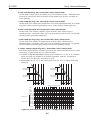
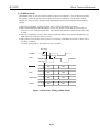
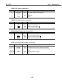
9) Timing charts
0.5us 0.5us 0.5us
Min. Min. Min.
DATA 1 to 8
STROBE
BUSY
ACKNLG
4us or 0.9us
Figure 2-9 Timing Chart (Compatible mode)
2-15
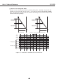
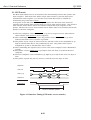
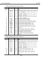
Part 2: Product Specifications
BJC-6000
Negotiation
Setup
Data Transmission (from printer to host computer)
1284 Active
Ack Data Req
Bit2
Bit6
Bit3
Bit7
Data Avail
Bit0
Bit4
Xflag
Bit1
Bit5
Data (1~ 8)
0000 0000
Host Busy
Host Clk
Ptr Clk
Ptr Busy
Printer Busy Status
Figure 2-10 Timing Chart (Nibble mode)
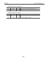
Negotiation
Setup
Data Transmission (from computer to printer)
1284 Active
Ack Reverse
Data (1~ 8)
Host Ack
0001 0000
Byte0
Byte1
DATA
Cmd
Host Clk
Periph Clk
Periph Ack
Periph Req
Xflag
Periph Ack
(HIGH)
Figure 2-11 Timing Chart (ECP mode)
2-16
Termination
Part 3
OPERATING
INSTRUCTIONS
Page
3- 1
3- 1
3- 2
3- 3
3 -10
3 -11
3 -11
3 -12
3 -12
3 -13
3 -14
3 -15
3 -16
3 -18
1. PRINTER SETUP
1.1 Unpacking
1.2 Installation Location
1.3 Installation
1.4 Names of Parts and Their Functions
2. TRANSPORTING THE PRINTER
2.1 Transporting the Printer
3. PRINTER SERVICE FUNCTIONS
3.1 Error Indications
3.2 Description of Error Indications
3.3 BJ Status Monitor
3.4 Function Settings
3.5 Off-Line Operations
3.6 Service Mode
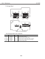
Part 3: Operating Instructions
BJC-6000
1. PRINTER SETUP
1.1 Unpacking
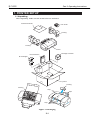
After unpacking, make sure the items below are included:
Quick Start Guide
Ink Tanks
Packing
Packing
Printer
Cartridge Container
Documentation
BJ Cartridges
Carton
Packing
Packing
Tape
Tape
Tape
Figure 3-1 Packaging
3-1
Part 3: Operating Instructions
BJC-6000
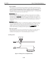
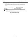
1.2 Installation Location
To ensure optimum performance, install the printer where there is adequate space.
The figure below illustrates the printer's outside dimensions.
Approx. 275 mm
Approx. 270 mm
Approx. 470 mm
Approx. 195 mm
Figure 3-2 Printer Dimensions
NOTE
Use the printer where the ambient temperature is between 5°C and 35°C,
and the ambient humidity is between 10% and 90% (no condensation).
Install the printer on a stable and horizontal surface free of vibration.
Do not install the printer where it is subject to direct sunlight or where it
may be subject to rapid fluctuations in temperature, such as close to air
conditioners. Also, do not leave the printer in a car where it may be
subject to a rapid rise in temperature.
Do not install the printer where it may be subject to excessive amounts of
dust, or subject to sea breezes or other sources of salinity.
Do not install close to a TV set, loudspeaker, or other sources of strong
magnetism.
3-2
Part 3: Operating Instructions
BJC-6000
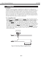
1.3 Installation
Set up the printer as follows.
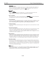
1.3.1 Connecting the interface cable
1) Make sure both the printer and the computer are switched OFF.
2) Connect the interface cable to the interface connector on the printer. Lock the
connector clips.
3) Connect the other end of the interface cable to the computer.
Figure 3-3 Connecting the Interface Cable
1.3.2 Connecting the power cord
1) Connect the plug of the power cord to a wall outlet.
2) Press the printer's POWER button. The buzzer sounds and the POWER lamp blinks
in green indicating that the printer is in the initialization process. After
initialization, the POWER lamp lights in green. If BJ cartridges are not installed, the
POWER lamp lights in orange, the buzzer sounds six times, and the carriage moves
to the cartridge replacement position.
Figure 3-4 Connecting the Power Cord
3-3
Part 3: Operating Instructions
BJC-6000
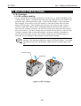
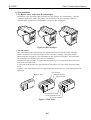
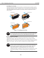
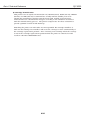
1.3.3 Installing the BJ cartridges
This printer can be used with the Black, Color, and Photo BJ cartridges, in the
following combinations : Black/Color BJ cartridges or Photo/Color BJ cartridges.
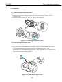
a) Removing head protection from the BJ cartridges
Remove the BJ cartridge from its package, and remove the head cap that protects
the nozzles, and the protective tape from the cartridge, as shown in the figure below.
Protective Tape
Head Cap
Figure 3-5 Removing Head Cap and Tape from BJ Cartridge
CAUTION
Do not reuse head caps or the protective tape that has been removed from
a BJ cartridge. It may cause of nozzle clogging or mixing of inks. Be
careful not to touch the nozzles when removing the tape, otherwise the
nozzles may be damaged or collect dirt, resulting in poor printing. Do not
shake the BJ cartridge after removing the head cap and tape, as ink may
scatter.
3-4
Part 3: Operating Instructions
BJC-6000
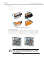
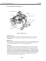
b) Installing the BJ cartridges
Open the printer cover to install the BJ cartridges on the carriage. Install the Color
BJ cartridge on the right side of the carriage. Install either the Black or Photo BJ
cartridge on the left side of the carriage. After installing the BJ cartridges, secure
them by lowering the cartridge lock lever. Remove the protective tanks from the BJ
cartridges.
Cartridge Lock Lever
Protective Tanks
Figure 3-6 Installing BJ Cartridges
CAUTION
NOTE
If both the left and right BJ cartridges are not installed correctly, the
carriage may fail to return to its home position when the cover is closed.
In this case, ensure that the BJ cartridges are installed firmly in the
correct position. If the carriage does not return to the home position, refer
to Part 5: 6 TROUBLESHOOTING (Page 5-13).
If the front cover is left open for ten minutes with both BJ cartridges
installed, the buzzer sounds for 30 seconds, and the carriage moves to the
capping position to protect the BJ cartridges' nozzles.
3-5
Part 3: Operating Instructions
BJC-6000
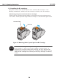
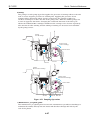
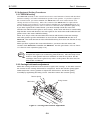
c) Installing the ink tanks
Peel off the protective film from the ink tank, and slowly turn the protective cap off.
Install the ink tanks in the BJ cartridges in the correct positions as indicated by the
label affixed inside the printer. When the cover is closed, the printer undergoes the
ink tank initializing process (approx. 30 seconds), and the carriage moves to the
home position.
Protective Cap
Protective Film
Protective Cap
Protective Film
Figure 3-7 Installing the Ink Tanks
CAUTION
The ink tanks other than the black ink tanks are identical in shape and
size. Paying attention to the colors of the ink tanks, install them in their
correct positions as indicated by the label affixed inside the printer.
d) Replacing the BJ cartridges
When the printer's front cover is opened, the carriage moves to the cartridge
replacement position. Raise the cartridge lock lever to remove the BJ cartridge.
Replace the cartridge with another one and lower the cartridge lock lever to secure it.
When the front cover is closed, the printer starts the BJ cartridge initializing process
(approx. 30 seconds). Store the removed cartridge in the cartridge container.
CAUTION
When switched OFF, the printer moves the carriage to the capping
position so that it is locked in place by the carriage locking mechanism.
Never pull the carriage's ribbon cable to move the carriage. When the
buzzer sounds four times and the carriage does not return to the
replacement position, even though the front cover is open, the BJ
cartridges may have overheated. Close the front cover and wait for a while
to let the BJ cartridges cool down naturally before reopening the front
cover.
3-6
Part 3: Operating Instructions
BJC-6000
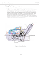
e) Replacing the ink tanks
For the Black, Color and Photo BJ cartridges, each ink tank can be individually
replaced.
1) When to replace the ink tank
Replace the ink tank with a new one if no ink can be seen inside, or as indicated by
the ink-out alarm, or if it was unpackaged for more than six months and printing
quality does not improve even after several cleanings.
NOTE
If printing quality still does not improve, even with a new ink tank
installed, perform cleaning operations 1-5 times. If this does not solve the
problem, replace the BJ cartridge.
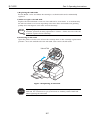
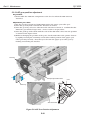
2) Removing an ink tank
Open the printer's front cover to have the carriage move to the cartridge replacement
position. Press the unlock tab of the ink tank, and remove the ink tank.
Unlock Tab
Figure 3-8 Replacing an Ink Tank
CAUTION
The ink supply pieces and nearby areas of the ink tank may be stained
with ink. Be careful not to get your hands or clothing stained with ink
when replacing the ink tank.
3-7
Part 3: Operating Instructions
BJC-6000
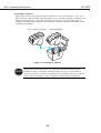
f) Cartridge container
This printer comes with a BJ cartridge container to store BJ cartridges. Once you
have removed a BJ cartridge from the printer, store it in this cartridge container, ink
tanks installed in place. If the BJ cartridge is left in open air, its nozzles may be
damaged or clogged by dried ink. The cartridge container can hold one Black, Color
or Photo BJ cartridge.
Color or Photo BJ Cartridge
Black BJ Cartridge
Figure 3-9 Cartridge Container
CAUTION
Always store a BJ cartridge in the cartridge container with ink tanks
installed in place, otherwise, ink may leak or dry up. Do not shake or
drop the cartridge container containing a BJ cartridge, otherwise, ink may
leak, or the BJ cartridge or the cartridge container may be damaged.
3-8
Part 3: Operating Instructions
BJC-6000
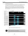
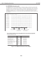
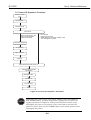
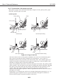
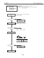
1.3.4 Aligning the print heads
As there are two BJ cartridges installed in this printer, even a slight difference in size
or seating position between them may result in inaccurate dot placement, and thereby
poor printing. To correct this, after installing the BJ cartridges, perform the
automatic head position adjustment, one of the utilities the printer driver package
provides. If a computer is not available, you can still perform the head position
adjustment in service mode. For the procedures, refer to Part 3: 3.6.1 Service mode
operations (Page 3-18). Set at least one sheet of B5 (or larger) plain paper in the ASF,
and select the head position alignment pattern in the test print area of the printer
driver's Utility sheet.
LED calibration
360-dpi vertical alignment
adjustment
360-dpi bi-directional rough
adjustment
360-dpi bi-directional fine
adjustment
180-dpi bi-directional rough
adjustment
180-dpi bi-directional fine
adjustment
360-dpi horizontal alignment
forward rough adjustment
360-dpi horizontal alignment
forward fine adjustment
360-dpi horizontal alignment
reverse rough adjustment
360-dpi horizontal alignment
reverse fine adjustment
180-dpi horizontal alignment
forward rough adjustment
180-dpi horizontal alignment
forward fine adjustment
180-dpi horizontal alignment
reverse rough adjustment
180-dpi horizontal alignment
reverse fine adjustment
720-dpi horizontal alignment
forward rough adjustment
720-dpi horizontal alignment
forward fine adjustment
1440-dpi horizontal alignment
forward rough adjustment
1440-dpi horizontal alignment
forward fine adjustment
Printing position check
pattern
Figure 3-10 Print Position Adjustment Pattern
CAUTION
Use paper of B5 size or larger for the automatic head position adjustment,
otherwise, the platen may be smeared with ink.
3-9
Part 3: Operating Instructions
BJC-6000
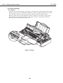
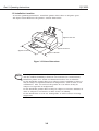
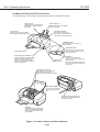
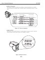
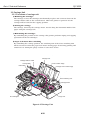
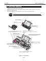
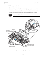
1.4 Names of Parts and Their Functions
The main parts of the printer and their functions are illustrated below.
Paper Guide
Paper Support
Lightly press this guide against
the left side of paper sheets to
align them.
Extend this paper rest to support
larger size paper.
Front Cover
Auto Sheet Feeder
Open this cover when replacing
BJ cartridges, clearing paper-jams.
Set sheets of paper here.
This feeder automatically feed
them into the printer one by one.
POWER button
Press this button to power on or
off the printer.
RESUME button
After correcting a problem, and
then press this button to make
the printer ready.
Paper Output Tray
Paper Thickness Selector
Indicator
Use this selector to adjust the gap
between the print head and the
paper for different paper types.
Set it to the uppermost position for
normal plain paper.
Operator Panel
Not lit when powered off.
When lit in green, the printer is
ready to print.
When lit or blinking in orange, an
error has occurred, and the print
cannot print.
Cartridge Lock Lever
Use this lever to secure the BJ
cartridges to the carriage.
Raise it to remove the BJ cartridge.
Manual Feed Slot
Use this slot to manually
feed a single sheet at a
time.
Parallel Interface Connector
Connects to the interface cable
from the computer.
Carriage
The left side of the carriage holds
the Black or Photo BJ cartridge,
and the right side holds the Color
BJ cartridge.
Figure 3-11 Names of Parts and Their Functions
3-10
Part 3: Operating Instructions
BJC-6000
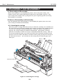
2. TRANSPORTING THE PRINTER
When carrying or transporting the printer, keep BJ cartridges installed in the printer, or
stored in the cartridge container. This prevents the ink from leaking or drying out in the
nozzles during transportation. To prevent ink leakage, transport the printer with the ink
tanks installed in the BJ cartridge.
2.1 Transporting the Printer
When transporting the printer, follow the procedures below:
Press the POWER button to turn off the printer. The POWER indicator will go out.
Disconnect the interface cable.
Unplug the power cord from the wall outlet.
Open the front cover and check that the carriage is locked in the capping position (on
the right side of printer). If the carriage is not in the capping position, move it
manually to the capping position, and secure it there with tape.
5) Close the cover.
6) Pack the printer in its' original packing in its' original carton. If the original packing
materials are not available, wrap the printer with sufficient shock absorbing material.
1)
2)
3)
4)
CAUTION
Do not unplug the printer before switching off the printer with the POWER
button, otherwise, the BJ cartridges' nozzles will not be capped, which may
result in ink may leak or dry-out. Do not carry a BJ cartridge and its ink
tanks separately.
3-11
Part 3: Operating Instructions
BJC-6000
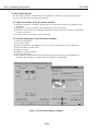
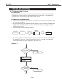
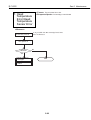
3. PRINTER SERVICE FUNCTIONS
3.1 Error Indications
This printer displays errors with the indicator lamp and buzzer. Also, when an error
occurs during printing, an error code is displayed on the status monitor to indicate the
type of the error.
POWER
RESUME button
button
Indicator
Figure 3-12 Operator Panel
For troubleshooting procedures, refer to Part 5: 6 TROUBLESHOOTING (Page 5-13).
TABLE 3-1 ERROR INDICATIONS
Errors
[Recoverable by user]
Paper feed error
Paper jam
Ink out
BJ cartridge mis-installed
No BJ cartridge
BJ cartridge error
Waste ink warning
Auto head adjustment error
Indicator
Lights
Lights
Lights
Lights
Lights
Lights
Lights
Lights
in
in
in
in
in
in
in
in
Beeps
Orange
Orange
Orange
Orange
Orange
Orange
Orange
Orange
2
3
4
5
6
7
8
9
times
times
times
times
times
times
times
times
Error
code
Reference
page
Page
Page
Page
Page
Page
Page
Page 5-29
[Unrecoverable by user]
ROM error
Blinks in Orange 1 time
10 times
Page
RAM error
Blinks in Orange 2 times 10 times
Page
EEPROM error
Blinks in Orange 3 times 10 times
6800 Page
Home position error
Blinks in Orange 4 times 10 times
5100 Page
Temperature sensor error
Blinks in Orange 5 times 10 times
5400 Page
Waste ink full error
Blinks in Orange 6 times 10 times
5B00 Page
Head temperature error
Blinks in Orange 7 times 10 times
5200 Page
Head temperature sensor error Blinks in Orange 8 times 10 times
5200 Page
Cartridge displaced error
Blinks in Orange 9 times 10 times
5600 Page
[Internal errors]
Ink sensor error
No indication
None
5910
Pump sensor error
No indication
None
5C00
Note: Internal errors are not displayed, but can be checked by printing the EEPROM
information (see Page 3-20).
3-12
5-25
5-25
5-27
5-28
5-28
5-28
5-18
5-18
5-18
5-19
5-22
5-22
5-23
5-23
5-24
Part 3: Operating Instructions
BJC-6000
3.2 Description of Error Indications
Errors recoverable by users:
1) Paper feed error
Paper feed operation fails to feed paper.
2) Paper jam error
Paper eject operation of 23 inches still fails to eject the paper.
3) Ink out error
The indicated ink tank is out of ink (ink chamber and sponge).
4) BJ cartridge mis-installed error
The BJ cartridges are not installed in their correct positions.
5) No BJ cartridge error
One or both of the BJ cartridges are not installed.
6) BJ cartridge error
One or both of the BJ cartridges are defective.
7) Waste ink warning
The calculated (and stored in EEPROM) amount of waste ink absorbed has reached
95% of the defined absorbing capacity.
8) Auto head adjustment error
The automatic head position adjustment has failed.
Errors unrecoverable by users:
9) ROM error
ROM checking during initialization is NG.
10) RAM error
RAM checking during initialization is NG.
11) EEPROM error
Writing to EEPROM has failed.
12) Home position error
The home position sensor is defective (broken circuit) or otherwise fails to detect home
position.
13) Temperature sensor error
The thermal sensor (TH201) on the logic board is defective (broken circuit).
14) Waste ink full error
The calculated (and stored in EEPROM) amount of waste ink absorbed has reached
the 100% of defined absorbing capacity.
15) Head temperature error
The inside temperature of the BJ cartridge is too high. This error should occur earlier
than the head temperature sensor error.
16) Head temperature sensor error
The thermal sensor in the BJ cartridge is defective.
17) Cartridge displaced error
The printer cannot detect the BJ cartridge when the carriage is out of the cartridge
replacement position.
18) Ink sensor error
Ink sensor checking during initialization is NG. If this error occurs, no indication is
made, but the printer will not check ink level and assumes that the level is normal
until the printer is switched off. You can confirm the error by printing the EEPROM
information.
19) Pump sensor error
Pump sensor checking during initialization is NG. No indication is made for this
error, but it can be confirmed by printing the EEPROM information.
3-13
Part 3: Operating Instructions
BJC-6000
3.3 BJ Status Monitor
The BJ status monitor window shows the printer's conditions and print-job progress.
You can stop the print-job from this window.
3.3.1 Main functions of the BJ status monitor
1) Show the printer's conditions and progress in real-time by means of graphics and
messages.
2) Display error types and show recommended recovery methods.
3) Show the types of the BJ cartridges installed and the ink-out warnings of ink tanks
by icon and name.
4) Can be used to abort the current print-job.
3.3.2 Items displayed on the BJ status monitor
1) Printer designation
2) Document name
3) Printer conditions (including error codes and recommended recovery methods)
4) Date and time of print start
5) Progress status
6) Number of pages printed
7) Print-job abortion
8) BJ cartridge identification (icons graphically display the types and positions of
installed BJ cartridges, and the ink-out warnings of ink tanks )
Figure 3-13 BJ Status Monitor (Sample)
3-14
Part 3: Operating Instructions
BJC-6000
3.4 Function Settings
As this printer has no physical function selectors, function settings can be set by using
the Canon printer driver.
3.4.1 Function settings using the printer driver
The printer driver's utility menu allows such operations and function settings as listed
below. In the menu, you can also invoke a special custom menu by, while pressing
the shift key, selecting Custom Settings.
1) Cleaning
2) Head refreshing
3) Nozzle check pattern printing
4) Head position adjustment
5) Printer power off
6) Automatic power supply setting
7) Launching the status monitor
8) Custom settings
· Enable ECP mode (disabled by default)
· Enable high speed printing (enabled by default): Printer's response time (ACKNLG)
is changed from 4 to 0.9 ms.
· Enable pause-between-pages (disabled by default): See Page 4-16.
· Enable pause-between-scanning (disabled by default): See Page 4-16.
· Enable automatic head position adjustment following BJ cartridge replacement
(disabled by default)
· Enable manual head position adjustment (disabled by default)
<In the special custom menu (special-custom/service mode)>
· Economic cleaning (disabled by default): Cleaning operation at power up is omitted
if the printer has been switched off for less than 72 hours. Enabling this function
is useful for saving ink, especially when the printer's power is provided through the
computer (possibility of nozzle clogging increases).
· Smear control (enabled by default): When the smear control (see Page 4-16) is
enabled, ink smearing of ink on paper due to paper-to-paper contact is prevented.
Smear control is especially useful for high duty printing on normal plain paper or
post cards. When smear control is disabled (and printed sheets are collected
directly following printing), throughput increases.
Special custom menu
Figure 3-14 Printer Driver Utility (Sample)
3-15
Part 3: Operating Instructions
BJC-6000
3.5 Off-line Operations
This printer has three operations which can be performed independent of the computer:
To select these operations, while holding down the RESUME button, power on the printer
by pressing the POWER button, confirm the specified number of beeps, and then release
the RESUME button.
Operations
Cleaning
Nozzle check pattern printing
Roller cleaning
Number of beeps Remarks
1 time
2 times
Printer prints one sheet and powers
down.
3 times
One cleaning sheet is fed and ejected
to clean the rollers.
3.5.1 Cleaning
With the printer powered on, hold down the RESUME button and after confirming one
beep, release the RESUME button. The cleaning operation will start, cleaning both
(right and left) print heads. If you want to clean only one print head, connect the
printer to the computer, and perform the print-head cleaning from the computer
using the printer driver utility.
3.5.2 Nozzle check pattern printing
With the printer powered on, hold down the RESUME button and after confirming two
beeps, release the RESUME button. The nozzle check pattern printing will start,
feeding a sheet, which must be of B5 size or larger, from either the auto sheet feeder
or the manual feed slot, and print a standard pattern using all nozzles of both
installed BJ cartridges. If print defects are detected in the test print, perform printhead cleaning. If five or more cleaning operations fail to solve the problem, replace
the BJ cartridge with a new one.
CAUTION
Use paper of B5 size or larger for the nozzle check pattern printing. If you
use smaller paper, the platen may be smeared with ink.
NOTE
To abort the nozzle check pattern printing, press the POWER button. The
printer will switch itself off after ejecting the paper.
3-16
Part 3: Operating Instructions
BJC-6000
Black BJ Cartridge
Large dot printing
Color BJ Cartridge
Printed with the first nozzle
Printed with the first nozzle
Yellow
48 nozzles
Cyan
48 nozzles
Magenta 48 nozzles
Black 160 nozzles
Printed with the 48th nozzle
Printed with the 160th nozzle
Small-dot printing
Printed with the first nozzle
Printed with the first nozzle
Printed with the 48th nozzle
Printed with the 160th nozzle
360-dpi vertical
(Y)
180-dpi horizontal forward
(X1)
180-dpi horizontal reverse
(X2)
360-dpi horizontal forward
(X3)
360-dpi horizontal reverse
(X4)
720-dpi horizontal forward
(X5)
720-dpi horizontal reverse
(X6)
180-dpi bi-directional
(B1)
360-dpi bi-directional
(B2)
Figure 3-15 Nozzle Check Pattern Print (Sample for Black/Color Cartridge)
3.5.3 Roller cleaning
With the printer powered on, hold down the RESUME button and after confirming three
beeps, release the RESUME button. The roller cleaning will start, feeding a cleaning
sheet from the auto sheet feeder and ejecting it without printing so that paper dust is
removed it from the pick-up rollers and paper feed rollers.
3-17
Part 3: Operating Instructions
BJC-6000
3.6 Service Mode
This printer has a service mode for service-related settings or performing test printing.
The operator panel buttons are used to enter service mode.
3.6.1 Service mode operations
1) With the printer powered off, while pressing the RESUME button, press the POWER
button. The buzzer will sound once.
2) While holding down the POWER button, release the RESUME button. Press the
RESUME button twice in succession, and then release the POWER button. (Each time
the RESUME button is pushed, the buzzer will sound once.) The indicator will blink
in green, and then light in green.
3) Select one of the following service mode functions by pressing the RESUME button
the specified number of times.
Press
Zero times
1 time
2 times
Indicator
Green
Orange
Green
3
4
5
6
Orange
Green
Orange
Green
times
times
times
times or more
Functions
Service/factory test print
EEPROM information printing
EEPROM initializing (reset to default settings, but
model setting is not cleared)
Waste ink counter clear
Model setting
Automatic head position adjustment operations
Power off
4) Execute the function you have selected (except for model setting) by pressing the
POWER button. The buzzer will sound once. The printer will switch off itself after
performing the function.
For the model setting function, select BJF600 or BJC-6000 by pressing the RESUME
button zero or one time respectively. (The buzzer will sound each time the RESUME
button is pressed.)
Press
Zero times
1 time
2 times
Indicator
Green
Orange
...
Model
BJ F600
BJC-6000
Reserve
Validate the model you have selected by pressing the POWER button. The buzzer will
sound once. (The printer will switch off itself after performing the operation.)
CAUTION
Use the Black and Color BJ cartridges for the service/factory test printing.
It is not possible to enter Service Mode without cartridges installed. (Also,
the Photo and Color BJ cartridges cannot be used for service/factory test
printing.) If you have changed the model setting, perform the
service/factory test printing for confirmation.
3-18
Part 3: Operating Instructions
BJC-6000
3.6.2 Service/factory test print
The service/factory test print displays, in the header portion, such information as the
control ROM version, model setting, total sheets passed, and total waste ink
absorbed.
Currently installed
left and right cartridges
Model
ROM version
Total number of pages passed when
using Photo/Color cartridge
Total number of pages passed when
using Black/Color cartridge
ROM Ver Vx.xx BJF600 Use Head <BC-xx,BC-xx> HeadTemp0=xxx.x HeadTemp1=xxx.x EnvironmentTemp=xxx.x Bk=xxxxxxxxxx Cl=xxxxxxxxxx Ph=xxxxxxxxxx
Factory Area=xx xx xx xx xx xx xx xx LostInkCount =xx.x% Destination =xx
Total waste ink amount (absorption ratio of the waste ink absorber : % )
Figure 3-16 Service/Factory Test Print
3-19
Part 3: Operating Instructions
BJC-6000
3.6.3 EEPROM information print
The EEPROM stores such information as function settings, total sheets passed with
the Black/Color or Photo/Color cartridges, total waste ink absorbed, and records the
last three errors recoverable only by service personnel. The information stored in the
EEPROM is printed out as a hexadecimal dump in the EEPROM information print.
The EEPROM information is useful especially for knowing how heavily the printer has
been used.
- EEPROM Information <Hex.>
Address
+0 +1 +2 +3 +4
00000000
05 20 00 0A 00
00000010
00 00 00 00 2A
00000020
35 6C B7 AB 33
00000030
14 00 0A 07 04
00000040
04 90 00 08 00
00000050
00 00 00 00 00
00000060
00 00 00 1D 00
00000070
00 00 00 00 00
00000080
00 00 00 72 00
00000090
3C 00 00 10 10
000000A0
0C 04 00 08 00
000000B0
00 00 00 00 04
000000C0
00 00 00 00 15
000000D0
04 19 57 AB 98
000000E0
35 36 30 30 35
000000F0
00 00 00 D6 67
+5
00
6A
BC
02
00
00
58
00
00
0C
0C
04
0B
1A
36
7C
+6
B8
51
E9
02
00
04
00
00
00
0C
0C
00
BB
72
30
73
+7
83
A1
71
02
44
44
1B
08
2E
08
00
00
19
13
30
FF
+8
00
38
32
00
00
00
00
00
00
0C
FD
00
35
00
35
01
+9
0C
54
DD
00
00
00
01
00
00
10
07
00
1A
45
36
FF
+A
9F
AA
02
00
00
00
00
00
00
0C
00
00
D5
93
30
FF
+B
40
A0
0C
00
44
00
2F
08
30
0C
00
00
C6
6B
30
FF
+C
09
1E
00
0A
00
00
00
00
83
0C
04
00
13
46
FF
FF
+D
35
16
00
80
00
00
06
00
00
10
04
00
0A
34
FF
FF
+E
1C
DA
00
00
00
02
00
00
00
0C
00
00
46
63
FF
FF
+F
28
3C
00
00
44
B9
00
08
00
0C
00
00
61
E3
F0
FF
Last error record Second error record Third error record
from the last
from the last
Error records are printed, in error code, for the last three errors which are recoverable
only by service personnel except for ROM/RAM errors in the order that the latest error
first and the oldest error last.
Error code
ASCII code representation
EEPROM error
Errors
6800
36 38 30 30
Home position error
Temperature sensor error
Waste ink full error
Head temperature error
5100
5400
5B00
5200
35
35
35
35
Head temperature sensor error
5200
35 32 30 30
Cartridge displaced error
Ink sensor error
Pump sensor error
5600
5900
5C00
35 36 30 30
35 39 31 30
35 43 30 30
31
34
42
32
30
30
30
30
30
30
30
30
Figure 3-17 EEPROM Information Print (Sample)
3-20
Part 3: Operating Instructions
BJC-6000
3.6.4 Resetting EEPROM
The EEPROM stores such information as function settings, total sheets passed with
the Black/Color or Photo/Color cartridge, total waste ink absorbed, and the last three
errors recoverable only by service personnel. Because the waste ink full error is based
on the data of the total waste ink absorbed as stored in the EEPROM, the Waste Ink
Counter must be cleared whenever the waste ink absorber has been replaced. If the
control board has been replaced, the new EEPROM must also be initialized. In this
case, the waste ink absorber must also be replaced with a new one. For the EEPROM
initializing procedure, refer to Part 3: 3.6.1 Service mode operations (Page 3-18).
3.6.5 Model setting
The control board of this printer is a common component for different printers. If you
have replaced the control board, it is necessary to set the mode setting as initial
information. For model setting procedures, refer to Part 3: 3.6.1 Service mode operations
(Page 3-18). After setting the model setting, perform the service/factory test printing
for confirmation.
3.6.6 Automatic head position adjustment
The automatic head position adjustment can be performed off-line (without being
connected to a computer). The printer will perform the automatic adjustment in the
same way as if the user initiated the adjustment from the computer via the printer
driver utility. For details, refer to Part 3: 1.3.4 Aligning the print heads (Page 3-9).
3-21
Part 3: Operating Instructions
BJC-6000
This page intentionally left blank
3-22
Part 4
TECHNICAL
REFERENCE
Page
4- 1
4- 1
4- 2
4- 3
4- 4
4- 9
4 -10
4 -10
4 -13
4 -15
4 -16
4 -16
4 -16
4 -16
4 -16
4 -17
4 -17
4 -19
4 -25
4 -28
4 -32
4 -36
4 -36
4 -37
4 -41
4 -42
4 -42
4 -44
1. OVERVIEW
1.1 Printer Block Diagram
1.2 Power On Sequence Flowchart
1.3 Flow of Print Signals
1.4 Print Driving
1.5 Power-Off Sequence Flowchart
2. FIRMWARE
2.1 Interface
2.2 Print Control
2.3 Automatic Printing Position Alignment Function
2.4 Pause Between Scanning
2.5 Pause Between Pages
2.6 Smear Control
2.7 Auto Power ON/OFF
2.8 Head Overheat Protection
3. PRINTER'S MECHANICAL SYSTEM
3.1 Overview
3.2 BJ Cartridge
3.3 Purge Unit
3.4 Paper Feed Unit
3.5 Carriage Unit
4 PRINTER'S ELECTRICAL SYSTEM
4.1 Overview
4.2 Control Unit
4.3 Power Supply Unit
5. DETECTION FUNCTIONS
5.1 Detection with Sensors
5.2 Other Detection Functions
Part 4: Technical Reference
BJC-6000
1. OVERVIEW
1.1 Printer Block Diagram
Print Position Sensor BJ Cartridge
ASF Unit
Paper Feed
Roller
Carriage
Purge
Sensor
Home Position
Sensor
Paper Feed Drive
Switching Unit
Paper Feed
Motor
Carriage
Motor
Ink Sensor
CN602
CN603
Mechanical
Cover Sensor
CN403
CN402
CN502 CN503
CN501
AC Adapter
+24V DC
Motor Control
Mechanical Control
+5V DC
Interface Control
CN404
Indicator Control
Switch Detection
Indicators
Operator Panel
Buttons
100 VAC
Figure 4-1 Printer Block Diagram
4-1
Paper End
Sensor
Printer Temperature
Sensor
Purge Unit
BJ Cartridge
Electronics
Part 4: Technical Reference
BJC-6000
1.2 Power On Sequence Flowchart
This flowchart shows the initial sequence this printer goes through from power-on to
on-line.
AC Connection
• Printer plugged In.
Software initialization
• MPU/printer controller initialized
• ROM/RAM check
• Ink sensor check
• Waste ink full error check
• Printer temperature sensor (TH201) check
• EEPROM read
Press POWER button
• Printer switched on
Beeper sounds once
Indicator blinks
(green)
Error check
• EEPROM error
• ROM error
• RAM error
• Waste ink full error
• Temperature sensor error
• Head temperature error
• Head temperature sensor error
I/F busy set
Home position
detection
Paper ejection
Self-cleaning
Error indication
• Paper left in the printer will be ejected.
Cleaning does not take place if:
• Wrong BJ cartridge configuration is installed
• BJ cartridge is faulty
• Printer is set to Economy Cleaning mode
Ink detection
Cover open check
• Carriage will move to the cartridge replacement position if the cover is open.
Indicator lights
(green)
I/F busy reset
Ready to print
Figure 4-2 Initial Sequence Flowchart
4-2
Part 4: Technical Reference
BJC-6000
1.3 Flow of Print Signals
The following outlines the flow of signals as the printer receives data from the host
computer and prints it.
a) The data from the host computer that contains control commands will be fed into the
printer controller via the parallel interface, which is controlled by the printer
controller, on the control board. The printer controller sends this data on the
dedicated bus to store it in the receive buffer in the DRAM.
b) The data saved in the receive buffer will be sent to the MPU, where it is separated
into control commands and print data according to the data stored in the control
ROM. The control commands will be processed in the MPU.
c) The print data will be extracted into the DRAM's print buffer.
d) The printer controller, on receiving the Print Start Request, allows the DMA to
transfer the print data from the print buffer into the printer controller.
e) The printer controller then converts the print data into serial data and sends it as
print signal to the BJ head. The serial print signal will be converted into one column
of parallel print data inside the BJ head. The data, as the print control signal, will be
output under the control of the printer controller.
f) The MPU, while controlling the printer controller, control ROM, and motor driver, and
monitoring the status of the BJ head and printer, controls the entire printing
operation.
DRAM
a
a
Host
Computer
b
Receive Buffer
Printer Controller
c
Print Buffer
e
d
b
BJ Head
c
f
Control Board
d
b
f
f
MPU
f
: Print Signals
: Control Signals
Figure 4-3 Flow of Print Signals
4-3
Control ROM
Motor Driver
Sensors
Part 4: Technical Reference
BJC-6000
1.4 Print Driving
The printer sends the control signals to the head in order to allow the head to discharge
ink for printing. These signals consist of the drive control signals that cause ink to be
discharged from the head nozzles, and the thermal control signal that controls the head
temperature to ensure constant ink discharge.
Both control signals are optimized by the printer controller and sent via the carriage
ribbon cable contact section to the head for optimal printing.
1.4.1 Print drive control
a) Black BJ cartridge control
The Black BJ cartridge has 160 nozzles. Each nozzle has two heater boards in an
array, large and small, one in front, the other in the rear. The front and rear heaters
will be controlled to provide multi-drop driving, with both driven simultaneously to
discharge a large drop, or with only the small one driven to discharge a small drop.
The head's 160 nozzles are divided into 10 blocks (16 nozzles per block), with all
blocks driven simultaneously, one nozzle per block in High Speed/Standard mode,
or 20 nozzles per block in all other cases.
The Heat ENABLE signals (HENB 0, 1, 2, 3) are the heater board's drive control
signals. These signals are always fed to the head during printing, using the Block
ENABLE signals (BENB 0,1), Even/Odd ENABLE signal (Even/Odd ENB), and the
Heat Select signals (HSEL1A0, 1A1, 1B0, 1B1, 2A0, 2A1, 2B0, 2B1) to select the
heaters to turn on. Turning HENB 0 and 2 on drives the Black BJ cartridge's large
heater while HENB 1 and 3 drive the small heater. A Heat ENABLE signal consists
of a pre-pulse and main pulse so that heater drive pulse width can be adjusted
according to the monitored head rank and internal temperature, etc., to always
ensure optimum ink discharge.
HSEL1A/1B
BE1
BE2
BE3
BE0
BE1
BE2
BE3
O
E
O
E
O
E
O
E
O
E
O
E
O
E
O
E
HSEL1A/1B
A/B
HSEL2A/2B
HSEL1A/1B
A/B
A/B
A/B
C/D
C/D
C/D
C/D
C/D
C/D
C/D
C/D
C/D
C/D
C/D
C/D
C/D
A/B
C/D
C/D
C/D
A/B
A/B
C/D
C/D
A/B
A/B
A/B
C/D
A/B
A/B
A/B
A/B
A/B
A/B
A/B
A/B
A/B
A/B
A/B
A/B
A/B
A/B
A/B
C/D
C/D
C/D
C/D
C/D
C/D
C/D
C/D
HSEL2A/2B
A/B
A/B
A/B
A/B
HSEL1A/1B
A/B
A/B
A/B
HSEL2A/2B
C/D
C/D
C/D
C/D
C/D
1 2 3 4 5 6 7 8 9 10 11 12 13 14 15 16 17 18 19 20 21 22 23 24 25 26 27 28 29 30 31 32 33 34 35 36 37 38 39 40 41 42 43 44 45 46 47 48 49 50 51 52 53 54 55 56 57 58 59 60 61 62 63 64 144
/160
:
BE0
HSEL2A/2B
BE0 - BE3: Block ENABLE 1 - 8
E: Even ENABLE
O: Odd ENABLE
A: Heat Select 1A
B: Heat Select 1B
C: Heat Select 2A
D: Heat Select 2B
Figure4-4 Printing Sequence (Black BJ cartridge, HQ mode)
4-4
Part 4: Technical Reference
BJC-6000
b) Color/Photo BJ cartridge control
The Color/Photo BJ cartridge has 144 (48 x 3) nozzles. Each nozzle has two heater
boards in an array, large and small, one in front, the other in the rear. The front
and rear two heaters will be controlled to provide multi-drop driving, with both
driven simultaneously to discharge a large drop, or with only the small one driven to
discharge a small drop. The head's 144 nozzles are divided into 9 blocks (16 nozzles
per block), with all blocks driven simultaneously, with one nozzle per block in the
High Speed/Standard mode (for speed), or 18 nozzles per block in all other cases.
The Heat ENABLE signals (HENB 0, 1, 2, 3) are the heater board's drive control
signals. These signals are always fed to the head during printing, using the Block
ENABLE signals (BENB 0, 1), Even/Odd ENABLE signal (Even/Odd ENB), and the
Heat Select signals (HSEL1A0, 1A1, 1B0, 1B1, 2A0, 2A1, 2B0, 2B1) to select the
heaters to turn on. HENB 0 and 2 drive the Photo BJ cartridge's rear heater while
HENB 1 and 3 drive its' front heater. HENB4 drives the Color BJ cartridge's rear
heater, and HENB 3 drives its' front heater. A Heat ENABLE signal consists of a prepulse and main pulse so that heater drive pulse width can be adjusted according to
the monitored head rank and internal temperature, etc., to always ensure optimum
ink discharge.
4-5
Part 4: Technical Reference
BJC-6000
1.4.2 Print drive method
The head can be driven in one of the following six drive methods: 180 x 180 dpi (large
dot), 360 x 360 dpi (large dot), 360 x 360 dpi (multi-drop drive), 360 x 360 dpi (largelarge dot), 720 x 720 dpi (small dot), and 1440 x 720 dpi (small dot) with the drive
method differing depending on whether printing is in the forward or reverse direction.
The Block ENABLE, Even/Odd ENABLE, and Heat Select signals are used to select
the heater(s) to turn on in the head nozzles.
Note that the head type (Black BJ cartridge, Color BJ cartridge or Photo BJ cartridge)
does not influence the type of print drive method.
a) 360 x 360 dpi (multi-drop drive, forward direction) control mode
In the multi-drop control mode, two nozzles 8 nozzles apart are driven (one large
drop driven and the other small drop driven) to print the large and small dots at
1/360-inch intervals.
1) Depending on the Odd/Even and Block ENABLE signals, nozzles No. 8 and No.
16, 8 nozzles apart, selected, using the Heat Select signals, nozzle No. 8 will be
heated by the large heater, and No. 16 by the small heater.
2) The nozzles next to No. 16 and No. 8, No. 15 and No. 7, will be heated similarly.
3) After nozzles No. 8 through No.1 have been heated by the large heater and
nozzles No. 16 through No. 9 by the small heater, No. 8 through No. 1 will be
heated by small heater and No. 16 through No. 9 by the large heater.
L
L
16 L
16
16
16 L
S 15
S 15
15 L
15 L
S 14
S 14
14 L
14
L
HSEL2A1(rear)
HSEL2A0 (rear)
S 13
S 13
13 L
13 L
HSEL2B1(front)
HSEL2B0 (front)
S 12
S 12
12 L
12 L
S 11
S 11
11 L
11 L
S 10
S 10
10 L
10 L
S 9
S 9
9 S
9
S
S 8
S 8
8 S
8
S
L 7
L
7 S
7
7
S
L 6
L
6 S
6
6
S
L 5
L
5 S
HSEL1A0 (rear)
5
5
HSEL1A1(rear)
S
L 4
L
4 S
4
4
HSEL1B0 (front)
HSEL1B1(front)
S
L 3
L
3 S
3
3
S
L 2
L
2 S
2
2
S
L 1
L
1
1
1
L
L
Carriage (right)
Carriage (left)
1/720 [inch] 1/720 [inch] 1/720 [inch]
1/720 [inch] 1/720 [inch] 1/720 [inch]
Direction of Carriage movement
Latch
ODD
EVEN
BENB0
BENB1
HSEL1A0
HSEL1B0
Carriage (left)
HSEL2A0
HSEL2B0
HSEL1A1
Carriage (right)
HSEL1B1
HSEL2A1
HSEL2B1
Large dot (L)
8
7
6
5
4
3
2
1
16
15
14
13
12
11
10
Small dot (S)
16
15
14
13
12
11
10
9
8
7
6
5
4
3
2
9
1
Figure 4-5 Print Drive Method (Multi-drop, forward direction)
4-6
Part 4: Technical Reference
BJC-6000
b) 180 x180 dpi (large dot, forward direction) control mode
In this mode, only 8 out of 16 nozzles in one block will be heated. This allows the
carriage to travel faster than it would if all 16 nozzles were heated, resulting in
faster printing.
c) 360 x 360 dpi (large dot, forward direction) control mode
In this mode, the nozzles that would have been heated simultaneously in a) multidrop drive will be heated sequentially one at a time from No.16 through No.1.
d) 720 x 720 dpi (small dot, forward direction) control mode
In this mode, two nozzles 8 nozzles, apart from the other, will be heated
simultaneously, exactly the same way as in a) multi-drop drive mode, except that
the two nozzles print with small dots.
e) 360 x 360 dpi (large-large dot, forward direction) control mode
In this mode, two nozzles, 8 nozzles apart from the other, will be heated
simultaneously, exactly the same way as in a) multi-drop drive mode, except that
the two nozzles print with large dots to increase the printing density.
f) 1440 x 720 dpi (small-drop drive, forward direction) control mode
This mode allows nozzles 4 nozzles apart from the other to be driven two at a time,
separately, to print small dots at 1/360 intervals.
1) Odd/Even and Block ENABLE signals cause nozzles No. 16, 12, 8, 4, 4 nozzles
apart one from one another to be heated separately, with No. 16 and No. 8
heated first, and then No. 12 and No. 4 next.
2) Then nozzles No. 15, 11, 7, and 3 those next to No. 16, 12, 8, 4, will be heated the
same way.
16
15
14
13
12
11
10
HSEL2A0(Rear)
HSEL2B0(Front)
16
15
14
13
12
11
10
HSEL2A1(Rear)
HSEL2B1(Front)
9
9
8
8
7
7
6
6
5
HSEL1A0(Rear)
HSEL1B0(Front)
5
HSEL1A1(Rear)
HSEL1B1(Front)
4
3
4
3
2
2
1
1
1/1440 [inch]
1/1440 [inch]
Carriage (left)
Carriage (right)
Direction of Carriage Movement
Latch
ODD
EVEN
BENB0
BENB1
HSEL1A0
Carriage (left)
HSEL1B0
HSEL2A0
HSEL2B0
HSEL1A1
Carriage (right)
HSEL1B1
HSEL2A1
HSEL2B1
Small dot
16
12
15
11
14
10
13
9
16
12
15
11
14
10
13
9
8
4
7
3
6
2
5
1
8
4
7
3
6
2
5
1
Figure 4-6 Print Drive Method (1440 x 720 dpi, forward direction)
4-7
Part 4: Technical Reference
BJC-6000
g) Reverse direction print mode
In the reverse direction print mode, printing takes place similarly, except that the
nozzles are heated in the reverse order. As such, the signals (ODD/EVEN, BENB)
that determine the heating order are driven with timing reversed from that used in
forward direction printing.
16
15
14
13
12
11
10
HSEL2A0(Rear)
HSEL2B0(Front)
16
15
14
13
12
11
10
HSEL2A1(Rear)
HSEL2B1(Front)
9
9
8
8
7
7
6
6
5
HSEL1A0(Rear)
HSEL1B0(Front)
5
HSEL1A1(Rear)
HSEL1B1(Front)
4
3
4
3
2
2
1
1
1/360 [inch]
1/360 [inch]
Carriage (left)
Direction of Carriage Movement
Carriage (right)
Latch
ODD
EVEN
BENB0
BENB1
HSEL1A0
HSEL1B0
Carriage (left)
HSEL2A0
HSEL2B0
HSEL1A1
Carriage (right)
HSEL1B1
HSEL2A1
HSEL2B1
Large dot
1
2
3
4
5
6
7
8
9
10
11
12
13
14
Figure 4-7 Print Drive Method (Reverse direction)
4-8
15
16
Part 4: Technical Reference
BJC-6000
1.5 Power-Off Sequence Flowchart
Beeper sounds
once
I/F busy set
Indicator blinks
Error reset
When BJ cartridge or ink
tank is replaced while
replacing cartridge
• No cartridge
• Capping in progress
• While replacing cartridges, neither of the
two cartridges is in place.
Cleaning operation
Ink detection
Paper ejection
Capping
Sensor/BJ head drive power off
MPU/Printer controller
initialization
EEPROM write
Indicator off
I/F busy reset
END
Figure 4-8 Power-Off Sequence Flowchart
CAUTION
Unplugging the power cord to turn off the printer causes the printer to
shut off immediately, possibly stopping the capping process before the
capping operation is completed. If the printer has been turned off by
unplugging the power cord, plug the power cord back in and turn the
printer on again, then use the POWER button to turn off the printer before
unplugging the printer.
4-9
Part 4: Technical Reference
BJC-6000
2. FIRMWARE
2.1 Interface
This printer's interface supports compatible mode, nibble mode, and ECP mode in
compliance with the IEEE 1284 Parallel Interface Standards. The compatible mode is a
uni-directional data transfer protocol similar to the Centronics interface conventional
protocol. The nibble mode and ECP mode are bi-directional data transfer protocols
used to transfer to the host computer the status data, including the device ID, printer
status, etc. The printer uses the compatible mode or the ECP mode (forward transfer)
when transferring print data. It should be noted, however, that the computer must be
set to ECP mode for the printer to operate in ECP mode.
2.1.1 Compatible mode
In compatible mode, data is transferred in 8 bit units. Data gets transferred by the
handshake between the STROBE, BUSY, and ACKNLG signals. When data (Data 1-8)
and the STROBE signal are received from the host computer, the printer controller
controlling the parallel interface outputs BUSY and latches the data on the falling
edge of the STROBE signal. After outputting BUSY, the printer controller transfers
the latched data into the receive buffer inside the DRAM through the DRAM dedicated
bus. When the printer controller is finished writing data into the receive buffer inside
the DRAM, it generates the ACNKLG signal and turns BUSY "Low" to indicate it is
ready for the next data input. This printer has a short default ACKNLG to reduce the
length of BUSY "High," making the printer response time shorter, thus making high
speed printing possible.
0.5us 0.5us 0.5us
Min. Min. Min.
DATA 1 to 8
STROBE
BUSY
ACKNLG
0.9us or 4us
Figure 4-9 Interfacing Timing (Compatible Mode)
4-10
Part 4: Technical Reference
BJC-6000
2.1.2 Nibble mode
The Nibble mode is used to transfer data to the host computer. It is in this mode that
the printer sends the printer status data to the host computer. Four input control
signals are used for data transfer with handshake between the PtrClk and HostBusy
signals.
1) The host computer, ready to receive data, causes HostBusy to go low.
2) After acknowledging that HostBusy is low, the printer sends the first four bits of
data out on the control signal lines, then makes PtrClk low to indicate that the data
is valid.
3) The host computer receives data after PtrClk has fallen, and causes HostBusy to go
high when the data has been received.
4) The printer repeats the above process to send the remaining four bits of data out to
the host computer.
(A signal going high or low means it rises or falls.)
Max.35 us
HostBusy
Max.35us
PtrClk
Min.45us
DataAvail
Bit0
Bit4
Xflag
Bit1
Bit5
AckDataReq
Bit2
Bit6
PtyBusy
Bit3
Bit7
Figure 4-10 Interface Timing (Nibble Mode)
4-11
Part 4: Technical Reference
BJC-6000
2.1.3 ECP mode
The ECP mode allows data to be transferred bi-directionally between the printer and
host computer. This mode also allows 2 byte data transfer to provide faster data
transmission and reception. It is for this reason that ECP mode is suitable for
transferring large amounts of data.
In response to the fall of the ReverseRequest signal, the direction of the data bus
switches from forward data transfer mode to reverse data transfer mode. The forward
data transfer mode allows data to be transferred from the host computer to the
printer, whereas the reverse data transfer mode allows data to be transferred from the
printer to the host computer.
(1) The host computer causes AckReverse to go low to request reverse data transfer
(data transfer from printer to host computer).
(2) After confirming AckReverse is low, the printer causes AckReverse to go low to
indicate that that reverse transfer is possible.
(3) The printer sends 1 byte of data out on the data lines and causes PeriphAck to go
high to tell that this data is not command but data. The printer then causes
PeriphClk to go low to tell that this data is valid.
(4) After confirming the signal in (3) is received, the host computer causes HostAck to
go high.
(5) The printer causes AckReverse to go high to have the data recorded in the host
computer.
(6) The host computer causes HostAck to go high to get ready for the next one byte of
data.
(7) The printer repeats the process above to send the next one byte of data.
PeriphClk
Host Ack
Data (1~8)
Byte0
Byte1
PeriphAck
Data
Cmd
ReverseRequest
AckReverse
Reverse transfer phase
Figure 4-11 Interface Timing (ECP mode, reverse transfer)
4-12
Part 4: Technical Reference
BJC-6000
2.2 Print Control
2.2.1 Print mode
The printer adjusts the carriage action and paper feed action according to the
installed cartridges, selected print media, printing quality, print data, etc. to ensure
high quality printing free from diffusion and density variations. Multiple passes are
used to provide staggered print timing with multiple nozzles used to print one luster,
so that the quantities of discharge that vary from nozzle to nozzle will be smoothed
out to minimize density variations. It is smear-free because it is not until the ink for
the last pass printed is fused on the paper that the next pass is printed. Printing can
be divided up to a maximum 8 passes, depending on the print media.
2.2.2 Multi-drop print
The BJ cartridges used in this printer incorporate drop-modulation technology,
allowing two ink drop sizes, large and small, to be ejected. This allows small dots to
be selectively used for printing in low-density areas to lessen granularity, while large
dots can be used in high-density areas to offer high speed printing. In the 720 dpi
and 1440 dpi print modes, only small dots are used continuously to provide highly
detailed printing.
2.2.3 Photo-print
The photo-print uses both the Photo BJ cartridge, which uses low density ink, and the
Color BJ cartridge to provide printing with up to 6 colors of ink. By printing in lowdensity image areas with ink of 1/3 normal ink density (photo-cyan and photo
magenta), printing with rich gradation and suppressed graininess is possible.
In the photo-print mode, each pixel is converted into a maximum of 4 values
(expressed by two bits), so that for each 360 dpi pixel, up to 4 gradations of each color
can be printed in a combination of large and small dots. The 6 ink colors of the Photo
BJ cartridge and Color BJ cartridge allow a more dynamic range of printing colors,
thus providing higher printing density using less ink than would have been possible
with 4 low-density ink colors.
2.2.4 Automatic switching control of printing nozzles
When the printer is set to the normal (for speed) plain paper mode (1 path) with the
Black BJ cartridge (160-nozzle) installed, the number of nozzles to be used for
printing will be automatically set within the nozzle range 48 - 160 during printing
according to the image data to be printed. Continuous printing with black will be
performed with 160 nozzles, but, in areas with color data, 48 nozzles will be used for
printing to prevent running.
4-13
Part 4: Technical Reference
BJC-6000
TABLE 4-1 PRINT MODE LIST
Regular Color Ink System (Black/Color BJ Cartridge)
High speed
Standard
(for speed)
High quality
Highest quality
Printing
mode
180 x 180 (L)
360 x 360 (L)
360 x 360 (L)
360 x 360 (L/S)
720 x 720 (S)
1440 x 720 (S)
Resolution
(dpi)*1
2
2
2
4
2
2
1 pass/Bi
1 pass/Bi
...
2 pass/Bi
4 pass/Uni
...
Transparencies
...
2 pass/Uni
(4 pass)
...
4 pass/Uni
(*3)
...
...
BPF
...
...
6 pass/Uni
(4 pass)
6 pass/Uni
(*3)
...
...
Fabric sheet
...
...
...
...
...
...
Glossy paper
...
...
...
4 pass/Uni
6 pass/Uni
(8 pass)
6 pass/Uni
(8 pass)
Glossy film
...
...
...
4 pass/Uni
6 pass/Uni
(8 pass)
...
High-resolution
paper
...
2 pass/Bi
...
3 pass/Bi
(4 pass)
4 pass/Uni
4 pass/Uni
Postcard
...
1 pass/Uni
...
3 pass/Bi
(4 pass)
4 pass/Uni
...
High quality
Highest quality
Printing
mode
Paper
Plain paper
Standard
(for quality)
Gradation
(/dot)
*2
(L = large dot, S = small dot ; Bi = bi-directional Uni = uni-directional
Photo-color Ink System (Photo/Color BJ Cartridge)
High speed
Standard
(for speed)
180 x 180 (L)
360 x 360 (L)
360 x 360 (L)
360 x 360 (L/L)
360 x 360 (L/S)
720 x 720 (S)
Resolution
(dpi)*1
2
2
2
4
4
2
Gradation
(/dot)
1 pass/Bi
1 pass/Bi
...
...
2 pass/Uni
2 pass/Uni
*2
Transparencies
...
2 pass/Uni
...
4 pass/Uni
...
...
BPF
...
...
...
6 pass/Uni
...
...
Fabric sheet
...
...
6 pass/Uni
...
...
...
Glossy paper
...
...
...
...
4 pass/Uni
6 pass/Uni
Glossy film
...
...
...
...
4 pass/Uni
6 pass/Uni
High-resolution
paper
...
2 pass/Bi
...
...
3 pass/Uni
4 pass/Uni
Postcard
...
1 pass/Uni
...
...
3 pass/Uni
4 pass/Uni
Paper
Plain paper
Standard
(for quality)
(L = large dot, S = small dot ; Bi = bi-directional Uni = uni-directional
*1 (large)-printed with large drops; (small)-printed with small drops; (large/small)-printed with
large and small drops
*2 Number of printing passes/Printing direction:
The bracketed numbers indicate the number of passes in gray-scale mode if different.
*3 Printed in 4 pass large/large mode
4-14
Part 4: Technical Reference
BJC-6000
2.3 Automatic Printing Position Alignment Function
This printer features the automatic printing position alignment function so that the
difference between the installed left and right BJ cartridges in vertical/horizontal
printing position and bi-directional printing position will be automatically adjusted.
After the automatic printing position adjustment patterns are printed, each under
slightly different conditions, Automatic Printing Position Alignment is performed
through the reflection of the patterns by the print position sensor, comprised of a red
LED and a photosensor, which is installed on the carriage. The variations in the
photosensor output are used to calculate the optimum printing position compensation
value. Based on the compensation value obtained, the printer corrects for the
difference in vertical/horizontal printing position and bi-directional printing position
between the right and left cartridges.
The Auto Printing Position Alignment starts with the calibration of LED and
photosensor sensitivity to correct variations between them. Then the difference in
vertical printing position between the left and right cartridges will be compensated for,
followed by the adjustment of bi-directional printing position for each printing mode,
and then the adjustment of the horizontal printing position to the accuracy of ±1 pixel,
after which finer adjustments will automatically be conducted. The adjustment
patterns will be printed in both black and cyan, as a red LED is used as the light
source.
For automatic printing position alignment, you must use B5 or larger paper.
LED
Photosensor
Paper
Standard dot
Mis-aligned dot
Shifted in - direction
Printing positions coincide
Shifted in + direction
Figure 4-12 Automatic Printing Position Alignment
CAUTION
Do not perform automatic printing position alignment with the front cover
open, as external light may make accurate measurements impossible. For
this reason, during servicing, do not perform automatic printing position
adjustment with the front cover open or upper cover removed.
4-15
Part 4: Technical Reference
BJC-6000
2.4 Pause Between Scanning
This printer features pause between-scanning to prevent bleeding and white clouding
be caused by differences in characteristics between color ink and black ink. This
function allows the border between the color ink and black ink to be detected during
internal print data processing so that, when detected, an appropriate pause will be
imposed on each print mode and color to prevent bleeding. Since this function
decreases the printer's throughput, it will only be activated when enabled by the user
and when printing on plain paper, for which this type of bleeding occurs easily.
2.5 Pause Between Pages
Immediately after ejection, printed paper is left to dry on the paper eject tray naturally.
If the next paper is ejected before the previous page has dried completely, ink-smearing
may occur. To prevent this, 1-minute pause will be imposed on for all pages before
printing starts, to delay paper ejection so the preceding page can dry. This is
particularly useful for slow-drying print media such as transparencies.
2.6 Smear Control
Immediately after being ejection, printed paper is left to dry on the paper eject tray
naturally. The next paper is ejected before the previous page has dried completely, inksmearing may occur. To prevent this, wait-time is added into the printing process,
delaying paper ejection so the preceding page can dry. After printing at high speed with
the Black BJ cartridge at high duty on plain paper or postcards, this printer
automatically determines both the high duty printing position and time elapsed after
printing, to control smearing ( default setting is ENABLE.).
2.7 Auto Power ON/OFF
This printer can switch itself on in response to print signals from the host computer
and switch itself off if left for a certain period of time without incoming print signals.
These settings can be made with the printer driver. When Auto Power ON is enabled,
the printer powers on if more than 3 bytes of data are received consecutively. Thus, the
interface unit is enabled, even if the printer is switched off. When Auto Power OFF is
enabled, the printer powers off if a certain period of time has elapsed without receiving
print data from the host computer. If, however, an error exists, paper is in the manual
feed slot, or the front cover is open, the printer will not power off.
2.8 Head Overheat Protection
If the printer continues to print after ink has run-out, the bubble jet head will overheat.
To prevent this, when the head temperature sensor inside the bubble jet head detects a
temperature higher than the specified range, overheat protection is performed.
Protection level 1: Prevents the user from touching the hot aluminum plate of the
head when replacing the bubble jet head by preventing the carriage from moving to the
cartridge replacement position for fixed time, even if the front cover is open.
Protection level 2: If a further rise in temperature is detected, after printing 1 line of
text, the carriage returns to the home position for 3.5 seconds to allow cooling before
continuing printing. This protection continues for more than 20 seconds.
Protection level 3: If an even higher rise in temperature is detected, the printer sees
this as head temperature error and stops printing. If the problem persists, the printer
sees it as a head temperature sensor failure and displays the head temperature error
message. The ENABLE TIME can be 5 min., 10 min., 15 min., 30 min., or 60 min.
4-16
Part 4: Technical Reference
BJC-6000
3. PRINTER'S MECHANICAL SYSTEM
3.1 Overview
The printer's mechanical system is comprised of the BJ cartridges, carriage unit, purge
unit, paper-feed unit, and drive switching unit. The following describes each of these
units:
Carriage Unit
Paper Feed Unit
Drive Switching Unit
Purge Unit
BJ Cartridges
Figure 4-13 Printer's Mechanical System
3.1.1 BJ cartridge unit
There are 3 types of BJ cartridges: the Black BJ cartridge with 160 nozzles and a 360
dpi nozzle pitch, the Color BJ cartridge with 48 nozzles and a 360 dpi pitch per color
(yellow, magenta, and cyan), and the Photo BJ cartridge with 48 nozzles and a 360dpi
nozzle pitch per color (photo-black, photo-magenta, and photo-cyan). The user can
install the cartridges in accordance to his/her printing needs. Always install the
Color BJ cartridge on the right side of the carriage. The left side of the carriage is for
either the Black BJ cartridge or Photo BJ cartridge, depending on the specific printing
requirements. Each BJ cartridge has detachable ink tanks, making it possible to
replace only the ink tank.
3.1.2 Carriage unit
The carriage, with two BJ cartridges installed in it, moves back and forth, along the
horizontal width of the paper, by the carriage belt driven by the carriage motor. The
carriage position is controlled by the carriage motor drive pulses after its initial
position is detected by the home position sensor mounted on the carriage board. The
print signals from the control board will be transmitted via the carriage ribbon cable
to the BJ cartridges installed in the carriage. The carriage controls the paper feed
motor drive switching unit, driving of the paper feed and purge unit, and switching of
the auto-sheet feeder drive. The carriage also controls the position for which capping,
wiping, or pumping is performed by the purge unit for BJ cartridge maintenance.
4-17
Part 4: Technical Reference
BJC-6000
3.1.3 Purge unit
The purge unit, driven by the paper feed motor, is comprised of the wiper, pump, cap,
and carriage lock unit. The wiper unit keeps the BJ cartridge head face in good
condition to ensure high quality printing while the suction function ensures that the
ink in the nozzle can be easily discharged. When not in use, the unit protects the BJ
cartridge with its cap and secures the carriage by locking it in place.
3.1.4 Paper feed unit
The mechanical portion of the paper feed unit is comprised of the pick-up unit, paper
feed unit, and paper ejection unit.
Pick-up unit
Paper is supplied either from the auto-sheet feeder in auto paper feed mode, or from
the manual feed slot in manual paper feed mode. The auto-sheet feeder, driven by the
paper feed motor, can be loaded with various sizes of paper up to legal size and
automatically supplies paper (picks up and delivers the paper to the paper feed unit).
Paper feed unit
The paper feed unit, driven by the paper feed motor, turns the feed roller to
horizontally move the paper beneath the BJ cartridge print head while keeping the
paper level on the platen without cockling. To manually feed paper through this
printer, use the RESUME button, as there is no paper feed knob.
Paper ejection unit
The printed paper is ejected by the eject rollers into the paper eject tray.
4-18
Part 4: Technical Reference
BJC-6000
3.2. BJ Cartridge
3.2.1 Construction of the Black BJ cartridge
The Black BJ cartridge has a 160-nozzle multi-drop bubble jet head and a detachable
black ink tank.
a) Air path
Keeps the pressure inside the ink tank constant with the external atmospheric
pressure.
b) Ink chamber
Loaded with black ink. The ink in the ink chamber will be supplied via the sponge
to the BJ head. A sensor is used to check for ink.
c) Ink sponge
Saturated with black ink.
d) Ink supply piece
Supplies constant quantity of ink to the joint between the bubble jet head and ink
tank.
e) Ink filter
Keeps foreign matter from entering the bubble jet head.
f) Bubble jet head
Consists of 160 nozzles and signal contacts. It discharges the ink supplied from the
ink tank according to the print signals it receives via the signal contacts. Each
nozzle has two heater boards inside, one large and one small, for discharging ink.
By controlling the driving of the heater boards, multi-drop driving is conducted.
Label
Air Path
Ink Sponge
Ink Chamber
Ink Supply Piece
Ink Filter
Bubble Jet Head
Figure4-14 Black BJ Cartridge
4-19
Part 4: Technical Reference
BJC-6000
3.2.2 Construction of the Color and Photo BJ cartridges
Color and Photo BJ Cartridges come equipped with a multi-drop bubble jet head
comprised of 48 nozzles for each of the three colors, for a total of 144 nozzles, and
have separate, detachable ink tanks, one for each color.
a) Air path
Keeps the pressure inside the ink tank constant with the external atmospheric
pressure.
b) Ink chamber
Loaded with ink. The ink in the ink chamber will be supplied via the sponge to the
BJ head. A sensor is used to check for ink.
c) Ink sponge
Saturated with the ink of that color.
d) Ink supply pieces
Supplies constant quantity of ink to the joint between bubble jet head and ink tank.
e) Ink filter
Keeps foreign matter from entering the bubble jet head.
f) Bubble jet head
Consists of 144 nozzles and signal contacts. It discharges the ink supplied color by
color from the ink tanks according to the print signals it receives via the signal
contacts. Each nozzle has two heater boards inside, one large and one small, for
discharging ink. By controlling the driving of the heater boards, multi-drop driving
is conducted.
Label
Air Path
Ink Chamber
Ink Sponge
Ink Supply Pieces
Ink Filter
Bubble Jet Head
Figure4-15 Color/Photo BJ Cartridge
4-20
Part 4: Technical Reference
BJC-6000
3.2.3 Construction of the bubble jet head unit
a) Bubble jet nozzle
Ink absorbed in the ink sponge will be filtered through the mesh ink filter, then fed
to the bubble jet nozzles via ink pipes. When the head drive current passes through
a heater board in a nozzle, the ink will boil, producing bubbles. These small bubbles
eventually coalesce into one large bubble. The head drive current will be turned off
before the ink drop is discharged from the nozzle, but the after-heat of the heater
causes the bubble to grow larger and be discharged from the nozzle tip as an ink
drop. The nozzle is replenished with ink after the ink has been ejected.
NOTE
The print head uses semiconductor technology, in which the heaters and
I/C circuits are mounted on a silicon plate. This silicon plate with
electrical circuitry is bonded to an aluminum base which is then attached
to a molded plastic cover with nozzles.
Signal Circuit
Print Circuit Board
Ultra-thin Wire Connection
Wire Connection Protective Bond
Silicon Plate
Aluminum Plate
Heater Plate
Bubble Jet Nozzle
Ink Channel Connected to
Ink Sponge
(1) Heater Driving
Begins
(2) Heater Is Driven
Ink Filter
(3) Heater Driving
Stops
(4) Bubbles Contract to
form an Ink Drop
Joint Pipe
Plastic Cover
Common Ink Chamber
(5) Ink Drop Is Ejected
Face Plate (part of plastic cover)
Figure 4-16 Bubble Jet Nozzle (part)
4-21
Part 4: Technical Reference
BJC-6000
b) Nozzle arrangement
The bubble jet nozzles are lined up vertically at 1/360 inch pitch in one column.
Color and Photo BJ cartridge have 8 dummy nozzles separating the nozzles of each
color.
Black BJ Cartridge
Photo BJ Cartridge
Color BJ Cartridge
160th nozzle
160th nozzle
48 photo-black nozzles
48 nozzles
160th nozzle
8 dummy nozzles
48 cyan nozzles
48 photo-cyan nozzles
8 dummy nozzles
8 dummy nozzles
48 photo-magenta nozzles
48 magenta nozzles
8 dummy nozzles
1st nozzle
1st nozzle
48 yellow nozzles
1st nozzle
Figure 4-17 Nozzle Arrangement
c) Signal contacts
The bubble jet head signal contacts, in touch with the carriage contacts, transmit
control signals such as print signals to the bubble jet nozzles.
32 28 24 20 16 12
8
30 26 22 18 14 10
31 27 23 19 15 11
29 25 21 17 13 9
Figure 4-18 Signal Contacts
4-22
4
6
7
2
3
5
1
Part 4: Technical Reference
BJC-6000
TABLE 4-2 SIGNAL CONTACTS
Signal
IN/OUT
HVH
OUT
SUBH0
OUT
(SUBH1)
VHG
...
5 ,7, 8, 10
HDATA0 IN/OUT
9
(HDATA1)
HSEL1B0
OUT
11
(HSEL1B1)
HVDD
OUT
12
HCLOCK0 IN/OUT
13
(HCLOCK1)
LGND
OUT
14, 16
HSEL1A0
OUT
15
(HSEL1A1)
HSEL2A0
OUT
17
(HSEL2A1)
OUT
HSEL2B0
18
(HSEL2B1)
OUT
HLAH
19
OUT
ODD
20
EVEN
OUT
21
BENB0
OUT
22
BENB1
OUT
23
HENB0
OUT
24
(HENB4)
HENB1
OUT
25
(HENB5)
HENB2
OUT
26
(HENB4)
HENB3
27
(HENB5)
DIR
OUT
28
HRSTX
OUT
29
DIA0
IN
30
(DIA1)
DIK0
IN
31
(DIK1)
...
...
32
Pin No
1, 2, 3
4, 6
Function
Head drive voltage (VH)
Sub-heater drive signal
GND for Head drive voltage (VHGND)
Serial data (including head identification and rank resistance)
sent in synchronization with the clock signal (H_CLK)
Rear nozzle heater select signal for upper nozzles (1-8, 1724, ..., 145-152)
Head logic drive voltage (+5 V)
Clock signal for serial data transmission
GND for head logic drive voltage (HVDD)
Front nozzle heater select signal for upper nozzles (1-8, 1724, ..., 145-152)
Front nozzle heater select signal for lower nozzles (9-16,
25-32, ..., 153-160)
Rear nozzle heater select signal for lower nozzles (9-16, 2532, ..., 153-160)
Serial data latch timing signal
Odd-number nozzles select signal
Even-number nozzles select signal
Signal to generate heater enable decoder outputs
Signal to generate heater enable decoder outputs
Rear heater drive signal for nozzles 1-112 (or 1-144)
Front heater drive signal for nozzles 1-112 (or 1-144)
Rear heater drive signal for nozzles 1-112 (or 1-144)
Front heater drive signal for nozzles 1-112 (or 1-144)
Rear heater drive signal for nozzles 113-160
Front heater drive signal for nozzles 113-160
Serial data input/output direction control signal
Reset signal
Head temperature (diode) sensor's anode line
Head temperature (diode) sensor's cathode line
Not used
The bracketed signal name (.....) is the name used for Color/Photo BJ cartridge if
different from that used for Black BJ cartridge.
4-23
Part 4: Technical Reference
BJC-6000
d) Cartridge identification
This printer uses 5 signals, HCLOCK (Pin 13), HDATA (Pin 9), HLAT (Pin 19), HRSTX
(Pin 29), and DIR (Pin 28) to communicate serially with the bubble jet head to
identify the installed BJ cartridge and the head rank. Bubble jet head heater
characteristics are classified into 24 types according to the variations associated
with the manufacturing process. The printer compensates for these variations to
provide optimum control of ink discharge.
Switching the printer on with either an unrecognizable BJ cartridge installed, or
with one BJ cartridge not installed, will cause the carriage to move automatically to
the cartridge replacement position. Also, removing a BJ cartridge when the carriage
is not in the cartridge replacement position while the printer is switched on will
result in a NO BJ CARTRIDGE error.
4-24
Part 4: Technical Reference
BJC-6000
3.3 Purge Unit
3.3.1 Function of the purge unit
The purge unit keeps the BJ cartridge nozzles in good working condition to ensure
high printing quality. The unit is designed to provide both capping and cleaning
functions.
a) Capping
The capping function presses the purge unit's cap against the print head face to
prevent the nozzles from drying and becoming contaminated. During capping, a
cam is actuated to lock the carriage in place. During printing, capping starts 30
seconds or so after data stops. When printing is not performed, capping takes place
after a certain period of time (20 minutes in paper feeding mode, or 30 seconds in
other conditions) has elapsed since the last data was received, or when the POWER
button is used to switch the printer off.
b) Cleaning
The cleaning function includes the wiping action to wipe paper fibers or waste ink off
the head face plate, and the suction action to suck out ink from the head to refresh
the insides of nozzles with new ink, and the maintenance jet action to discharge the
ink from the nozzles into the maintenance jet splash guard for removing bubbles
from the head or dust around the outlet. The cleaning mechanism becomes
activated in the following cases to help maintain high quality printing.
Reference Ink Consumption (mg)
Black Color Photo
Power ON Initial power on (1 time only)
0.49 0.75 0.75
Switched on for the 1st time since connecting to AC (capped) 0.19 0.27 0.27
Switched on for the 1st time since connecting to AC (not capped) 0.34 0.53 0.53
72 hours or more elapsed since previous cleaning
0.19 0.27 0.27
Cleaning
0.19 0.27 0.27
Refreshing
0.34 0.53 0.53
Changing BJ cartridge/Ink tank
0.34 0.53 0.53
72 hours or more elapsed since previous cleaning
0.19 0.27 0.27
Before printing banner paper
0.19 0.27 0.27
(Specified number or more of dots or time elapsed since
previous cleaning)
Printer Status
Maintenance Jet Splash Guard
Purge Unit
Figure 4-19 Purge Unit
4-25
Part 4: Technical Reference
BJC-6000
3.3.2 Construction of the purge unit
Wiper Release Unit
Wiper Unit
Cap Unit
Carriage Lock Unit
Purge Drive Gear
Pump Unit
Air Valve Unit
Figure 4-20 Purge Unit
a) Purge drive gear
Receives the power of the feed roller driven by the paper feed motor via the drive
switching unit to drive the pump. The pump roller's position is detected by the
pump sensor.
b) Wiper unit
Operates when the carriage travels back and forth. It wipes off surplus ink from the
head face plate as the carriage moves right to left at the completion of cleaning. It is
constructed of two rubber wipers to enhance wiping performance,.
c) Cap unit
Uses the same rubber cap for both the capping action to protect the head, and for
the pumping action to suck ink. There are two rubber caps, one per BJ cartridge
installed on the carriage. Capping occurs by pressing the cap against the head's
face plate when the carriage moves to the capping position. The rubber caps in the
cap unit are connected to the pump unit and the air valve via the ink tube. During
cleaning, the unit sucks ink from the head using the pump. The sucked ink will be
sent to the waste ink absorber. After ink suction is completed, the carriage will be
moved to the position that opens the air valve and pumping will be performed to
suck out waste ink collected in the rubber cap.
4-26
Part 4: Technical Reference
BJC-6000
d) Pump
The pump is a tube pump type that applies the pressure of turning rollers to the ink
tube to create negative pressure for sucking ink. Applying the pressure of two
turning rollers alternately allows greater control over the amount of ink to be
sucked, and helps to reduce the size of the pump unit. With two similar pumps set
to turn in opposite directions, changing the rotational direction of the drive gear
allows the individual BJ cartridges installed in the carriage to be cleaned separately.
The amount of roller turning and the timing of turning are detected and controlled
by the pump sensor.
Carriage
Color BJ Cartridge
Cap
Reverse Turning
(Color BJ Cartridge)
Open
Pressure Rollers
Close
Pump Unit
Air Valve
Ink Tube
Waste Ink
Carriage
Black / Photo BJ Cartridge
Forward Turning
(Black/Photo BJ Cartridge)
Open
Pressure Roller
Close
Pump Unit
Air Valve
Waste Ink
Ink Tube
Figure 4-21 Pumping Operations
e) Maintenance jet splash guard
The maintenance jet splash guard receives the maintenance jet ink (test discharge to
maintain the nozzle) directly into the waste ink absorber through the hole by the
side of the platen.
4-27
Part 4: Technical Reference
BJC-6000
3.4 Paper Feed Unit
3.4.1 Functions of the paper feed unit
a) Paper feed function
This printer has two paper supply methods, using the auto-sheet feeder in
automatic paper feed mode, or the manual feed slot. The built-in auto-sheet feeder,
driven by the paper feed motor and loaded with paper, supplies paper into the
printer automatically. Also, feeding of postcards and envelopes can be performed
automatically without operating a mechanical paper selection lever. Manual paper
feeding also can be performed, even if paper is set in the auto-sheet feeder. When
paper is detected by the paper end sensor (photointerruptor-type), it will be fed
automatically to the print start position on the platen. Paper feeding action during
printing is controlled by the control of the paper feed rollers. The printed paper will
be ejected from the printer by the paper eject rollers.
ASF Paper Feed Path
Paper
Pick-up Roller
Paper End Sensor
Sensor Flag
Pressure Roller
Spurs
Manual Feed Path
Paper Feed Rollers
Eject Rollers
Figure 4-22 Paper Feed Path
4-28
Part 4: Technical Reference
BJC-6000
b) Paper thickness adjustment
The clearance between the head face of the BJ cartridge and the paper varies with
the thickness of the paper. Smaller clearance improves the printing quality however,
paper contacting the head face risks spoiling print quality or damaging the BJ
cartridge head face. This printer is equipped with a 2-position paper thickness
selector to provide constant paper clearance. The carriage shaft is supported by
means of an eccentric bearing. The paper thickness selector turns this eccentric
bearing to move the carriage up and down in order to adjust the head-to-paper
distance.
Carriage Guide Frame
Carriage
Eccentric Bearing
Carriage Shaft
Paper Thickness Selector Lever
Plain Paper Position
Thick Paper Position
Figure 4-23 Paper Thickness Adjustment Mechanism
4-29
Part 4: Technical Reference
BJC-6000
3.4.2 Construction of the paper feed unit
This printer's paper feed unit is mechanically comprised of the pick-up unit, paper
feed unit, and the paper eject unit.
a) Pick-up unit
Pick-up Roller
Paper
Pick-up Hook
Pick-up Corner
Pick-up Guide
Manual Paper Feeding
Stacked Paper
Envelope/Postcard Feeding
Plain Paper Feeding
Figure 4-24 Paper Feed Unit
The auto-sheet feeder for this printer eliminates the need for a mechanical papertype selector provided the paper satisfies the specifications. As a result, no
mechanical selector lever is in the auto-sheet feeder unit. The stacked papers are
locked in two places with hooks at the paper's leading edge to prevent paper from
skewing or warpage that could cause misfeeding.
Paper feed operation starts when, driven by the paper feed motor, the pick-up roller
starts turning. The two hooks at the paper's leading edge will be unlocked, allowing
the paper to be loaded onto the sheet feeder and hooked on the separator by one
corner. When the pick-up roller starts turning, the paper, with one corner
suppressed by the paper separator, will be separated and fed one sheet at a time to
the paper feed roller.
If the paper is a resilient type such as an envelope/thick paper (postcards, etc.,), it
pushes the paper separator over as it gets fed because the paper's resilience is
greater than the paper separator spring's return force.
4-30
Part 4: Technical Reference
BJC-6000
To manually feed paper, the user must insert the paper into the manual feed slot
until the paper end sensor detects it. In the manual paper feed mode, the pick-up
guide changes its position for the paper to pass through a different path from that in
which the auto-sheet feeder is used. As a result, manual paper feed mode is
possible even when the auto-sheet feeder is loaded with paper. When the paper
pushed in to the paper feed section is detected by the paper end sensor, it will be fed
to the print start position.
b) Paper feed unit
The printing unit clamps the paper on the platen between the pressure roller/paper
feed roller and the spurs/eject roller to provide a constant clearance between the
head and the paper. Control of paper feeding during printing is performed by
controlling the turning of the high precision ceramic-coated metal paper feed roller.
Paper is fed in steps of 1/720 inch.
c) Paper eject unit
The printed paper is ejected by the eject roller with its face clamped on the roller by
sharp toothed spurs. The paper eject unit consists of the eject roller and the spurs.
A cut sheet fed to the print start position will be printed at the platen. The cut sheet
is fed by the turning of the paper feed roller and pinch roller, and, after being
printed, will be ejected by the eject roller and spurs.
4-31
Part 4: Technical Reference
BJC-6000
3.5 Carriage Unit
3.5.1 Functions of carriage unit
a) Mounting BJ cartridges
The carriage secures BJ cartridges mechanically in place and connects them via the
carriage ribbon cable to the control board. When the printer is powered off, the
carriage will be locked in the capping position.
b) Driving the carriage
The carriage, driven by the carriage motor, travels along the horizontal width of the
paper using the carriage belt.
c) Maintaining BJ cartridges
By controlling the position of the carriage, this printer performs wiping and capping
operations on the BJ cartridges.
d) Paper feed motor drive switching
By controlling the carriage position, the switching arm of the drive switching unit
will be actuated so that the paper feed motor driving paper feed during printing will
switch over to driving the purge section or auto-sheet feeder.
Carriage Unit
Carriage Ribbon Cable
Carriage Belt
Home Position Edge
Idler Pulley
Carriage Lock Position Edge
Drive Switching Unit
Carriage Motor
Purge Unit
BJ Cartridges
Figure 4-25 Carriage Unit
4-32
Part 4: Technical Reference
BJC-6000
3.5.2 Construction of the carriage unit
Carriage Ribbon Cable
BJ Cartridge Mount
Home Position Edge
Carriage Lock Position Edge
Signal Contacts
Carriage Belt
Carriage Motor
Figure 4-26 Carriage Unit
a) BJ cartridge mount
BJ cartridges are secured to the carriage with the BJ cartridge lock lever. When a
BJ cartridge is secured in place to the carriage, the carriage board signal contact
pad contacts the BJ cartridge signal contacts, allowing print signals to be
transmitted from the control board. The home position edge is provided to interrupt
the light from the home position sensor on the chassis.
b) Carriage drive unit
Mechanical variances between the left and right BJ cartridges in vertical/horizontal
and bi-directional printing can be corrected automatically or manually by adjusting
printing timing. The carriage motor is a stepping motor that drives the carriage via
the carriage belt to travel along the horizontal width of the paper. The carriage will
be unlocked when the carriage lock position is detected by the home position sensor
(photointerruptor type) located on the rear of the carriage. The carriage is controlled
and driven by the stepping pulses fed to the carriage motor once the home position
edge is detected as the reference for subsequent position control. The carriage motor
is driven by the steady current generated by the motor driver, reducing drive loss
and operating noise.
4-33
Part 4: Technical Reference
BJC-6000
c) BJ cartridge maintenance
By controlling the carriage position, wiping and cleaning operations will be
performed on the BJ cartridge. During capping, as the carriage travels left to right,
the notch on the carriage causes the purge section wiper flag to move, raising the
wiper and capping the cartridge. When the carriage travels right to left, the cartridge
is wiped clean, after which the hook unit on the carriage unlocks the wiper latch,
lowering wiper.
Wiper Flag
Hook
Notch
Wiper Latch
Figure 4-27 BJ Cartridge Maintenance
4-34
Part 4: Technical Reference
BJC-6000
d) Paper feed motor drive switching unit
Depending on the carriage position, the drive switching unit switches the paper feed
motor's drive power over to drive the purge unit or the auto-sheet feeder. The slide
arm that travels in sync with the carriage action controls the operation of the
selector flag.
Slide Arm
Flag Clamp
Selector Flag
Purge Drive Gear
Drive Input Gear
ASF Drive Gear
Figure 4-28 Drive Switching Unit
When the purge unit is driven, the flag clamp on the slide arm secures the selector
flag. Turning the paper feed roller in the direction of paper feed transmits the
driving power to the purge unit's drive gear without causing the ASF drive gear to
turn. When the auto-sheet feeder is driven, the paper feed unit will be turned in the
opposite direction of paper feed once to allow the flag to move toward the slide arm
as the selector arm moves to the position where it supports the selector flag. With
the selector flag supported, turning the paper feed unit in the direction of paper feed
causes the ASF drive gear to start turning, and with it, pick-up operations
commence. When the slide arm moves out of the position where it supports the flag,
the ASF drive gear automatically stops turning when the pick-up action is complete.
Slide Arm
Selector Flag
(when ASF is driven)
Selector Flag
(when purge is driven)
Figure 4-29 Operation of the Drive Switching Unit
4-35
Part 4: Technical Reference
BJC-6000
4 PRINTER'S ELECTRICAL SYSTEM
4.1 Overview
The electronics of this printer can be functionally divided into the control unit and the
power supply unit. The control section converts the input data from the host computer
into print signals or printer control signals, and drives the BJ cartridges and motors
while monitoring all the sensors. The power supply unit converts the AC power into DC
power, and has the control board convert this DC power into each specific voltage
supplied to drive motors, ICs, BJ cartridges, etc.
Carriage Board
Control Board
AC Adapter
Figure 4-30 Printer's Electrical System
4-36
Part 4: Technical Reference
BJC-6000
4.2 Control Unit
4.2.1 Control unit block diagram
Control Board
Address Bus A1 - A21
C51~53
CE
25MHz
AD1~21
20MHz
0~15
A0~18
Control
ROM
D0~15
A1~21
D0~15
Data Bus D0 - D15
PE0,2
Ink Sensor
PE4
MPU
RAS,CAS
DRAM Bus DRAM
16-Mbit
MA0~9
MA
0~9
MD
0~15
AN0
Internal
Temperature
SensorTH201
A0~9
MD0~15
Buzzer
Power Switch
Reset IC
RESX
Carriage Board
BZ
P71
Reset Switch
I/O 1~16
INT 0~3
Printer Controller
Cover Sensor
P24
IRQ AN6
0~4
RESX
HRANK0,1
DIODE0,1
Print Position Sensor
Home Position
Sensor
BJ Cartridge Connector
PC0
H_D0,1
H_CLOK0,1
HSEL1A0,1 H_RSTX ODD,EVEN
HSEL1B0,1 H_LTH BENB0,1
DIR HENB0K*5
HSEL2A0,1
SUBH0,1
HSEL2B0,1
BJ Cartridge Connector
PC3
BJ Cartridges
Pump Sensor
2 Kbit
PB
0~3
PM
EEPROM
Carriage Motor
Driver IC
PM
Paper Feed Motor
PC1
Parallel Interface
Paper End Sensor
Error Indicator
Power Indicator
PA1
Figure 4-31 Control Unit Block Diagram
Purge
Sensor
AC Adapter
100VAC
Print Position Sensor
Paper Feed
Motor
CN603
Cover Sensor
+24V DC
CN403
BJ Cartridge
BJ Cartridge
Carriage
Paper Feed
Drive Switching
Unit
Ink Sensor
CN602
Paper Feed
Roller
Home Position
Sensor
Carriage
motor
CN402
CN502 CN503
Motor Control
Paper End
Sensor
CN501
Mechanical Control
+5V DC
Interface Control
CN404
Indicator Control
Switch
Detection
Operator Panel
Buttons
Indicator
Control Unit
Figure 4-32 Control Unit Function Diagram
4-37
Internal Temperature
Sensor
ASF Unit
Purge Unit
Part 4: Technical Reference
BJC-6000
4.2.2 Logic Components
RESUME Switch
LED
Cover Sensor
CN403
CN404
CN603
CN401
ROM
CN602
CN402
POWER Switch
Printer Controller
Motor Driver
Buzzer
EEPROM
DRAM
MPU
TH201
Paper End Sensor
Figure 4-33 Control Board
a) Printer controller
The printer controller incorporates the interface controller, print head controller,
buffer controller, DRAM controller, stepping motor controller and I/O ports and
operates in sync with the 25MHz external clock input.
Interface controller
Receives 8-bit parallel data sent from the host computer in sync with the data
strobe pulse (STROBE) through BUSY/ACKNLG handshake. Data received from
the interface will be stored in the receive buffer in the DRAM and analyzed by the
printer controller.
Print head controller
Reads the print data from the DRAM's print buffer and converts this parallel data
into serial data to send to the print head. At the same time, it counts the printing
dots needed to control the variable pulse width of the Heat ENABLE signal
(Pre/Main pulse width).
The printer controller's head drive signals include the Odd/Even ENABLE signal,
Block ENABLE signal, Heat Select signal, and Heat ENABLE signal. The printer
controller uses the Odd/Even ENABLE signal, Block ENABLE signal, and Heat
Select signal to select the discharge heaters inside the nozzle by time sharing, and
varies the pulse width of the Heat ENABLE signal to determine how long the
discharge heater to be heated should remain driven. When the head drive voltage
is on, the printer controller also uses the HDATA signal to send the head ID, rank
resistor value as 6-bit serial input data from BJ cartridges.
4-38
Part 4: Technical Reference
BJC-6000
Buffer controller
Writes the received data into the DRAM's receive buffer automatically, controls the
remaining receive buffer capacity, reads the print buffer automatically, and clears
the data that has been read. The print buffer manages two separate areas for the 2
heads.
DRAM controller
Performs control of the 16Mbit-DRAM's 16-bit data bus and 10-bit address bus,
READ/WRITE control, RAS/CAS control, and REFRESH control, using the bus
dedicated to DRAM which is separate from the MPU bus inside the printer
controller.
Stepping motor controller
Transfers to the driver IC the steady current drive waveforms needed to drive
motors. As the motor is sinuously driven, the data to be transferred to the IC is
16-bit/step drive waveform serial data that consists of motor drive current, motor
torque setting, phase information, etc.
Interrupt controller
The printer controller has 4 interrupt pins on it. The interrupt controller generates
parallel I/F, motor drive, and head drive interrupt requests to MPU(IC201). Also, it
accepts an interrupt signal from the reset IC.
I/O port
Sends indicator lighting and the power supply voltage output control signals as
output signals, receives sensor signals from the home position sensor, pump
sensor, and paper end sensor as input signals, controls the EEPROM data I/O,
and sends the motor driver reset signal as output.
b) MPU (IC201)
Incorporates a 32-bit CPU, 6Kbit work RAM, 21-bit address bus port, 16-bit data
bus port, interrupt controller, A/D converter, and I/O port. The MPU selects the
control ROM, printer controller, or DRAM according to the chip select signal.
Built-in CPU
32-bit CPU operates in sync with the 20MHz external clock input.
Address bus/Data bus
The 21-bit address bus and 16-bit data bus operate in sync with the 20MHz
external clock input.
Interrupt controller
Allows the MPU to receive the power on/off interrupt signal, as well as interrupt
signals from the printer controller.
4-39
Part 4: Technical Reference
BJC-6000
A/D converter
Detects the following analog signals:
Internal temperature analog signal from the thermistor on the control board.
Head temperature analog signal from the temperature sensors inside the BJ
cartridge.
Ink chamber ink detection analog signal from the ink sensor.
Density detection signal from the print position sensor for printing position
compensation.
I/O Port
Receives the cover sensor signal as input, and sends the lighting signal for the LED
inside the print position sensor as output.
c) DRAM (IC302)
Controlled by the printer controller, the 16Mbit-DRAM is used as a receive buffer,
download buffer, print buffer, and working area.
d) Motor driver IC (IC401)
Drives carriage motor and paper feed motor with steady currents generated
according to the drive current signal data (serial data) it receives from the printer
controller.
e) EEPROM (IC602)
Controlled by printer controller, the 2Kbit EEPROM stores in memory the quantity of
absorbed waste ink, paper feed count, and BJ cartridge mount/demount count. The
contents will be read when the printer is powered on, and written when powered off.
f) Control ROM (IC202)
8Mbit ROM containing the programs for controlling this printer.
4-40
Part 4: Technical Reference
BJC-6000
4.3 Power Supply Unit
4.3.1 Power Supply Unit Block Diagram
Carriage Motor (VM)
Paper Feed Motor (VM)
BJ Cartridge (HVH)
HVCONT(+24VDC output control signal)
+5V DC
DRAM
+3V
RGV3/inRGV3)
MPU
Printer Controller
DC/DC Converter
Control ROM
EEPROM
AC100V
AC Adapter
+24V DC
+5V DC
+5V DC(RGM5/RGV5I)
Print Position Sensor (VSEN)
Home Position Sensor (VSEN)
Ink Sensor (VSEN)
BJ Cartridge (HVDD)
Parallel Interface (VIF)
Figure 4-34 Power Supply Unit Block Diagram
4.3.2 Construction of Power Supply Unit
The power supply unit converts AC power line voltage into DC voltages that drive
motors, ICs, BJ cartridges, etc.
a) AC adapter
Converts the AC line voltage into 2 groups of DC voltages, +24 VDC, and +5 VDC.
The output of +24 VDC is controlled by the output signal (HVCONT) from the
printer controller. The +24 VDC is used to drive the head, and carriage motor/paper
feed motor as HVH, and VM, respectively. Note that there is no output of HVH if the
head is at the replacement position or at home position. The +5 VDC is always
output by the adapter. Except for sensors, driver ICs, and BJ cartridges, all
hardware components are active while AC power is supplied.
b) DC/DC converter
Located on the control board to convert +5V to RGV5/RGV5I(+5 VDC) and
RGV3/inRGV3(+3.3 VDC) and output them. RGV5/RGV5I is used as the drive
power for EEPROM and reset, and power voltages for HVDD, VIF, and VSEN. Note
that the output of power voltages of HVDD, VIF, and VSEN are controlled by printer
controller. RGV3/inRGV3 is used as power for the printer controller, MPU, DRAM,
and control ROM, and as pull-up for switches.
The +3.3VDC is intended to reduce power consumption when the printer is switched
off as compared with +5 VDC.
4-41
Part 4: Technical Reference
BJC-6000
5. DETECTION FUNCTIONS
5.1 Detection with Sensors
This printer has the following sensors detect the printer's status.
Cover Sensor
Paper End Sensor
Internal Temperature
Sensor
Pump Sensor
Print Position Sensor
Home Position Sensor
Ink Sensor
Figure 4-35 Sensor Positions
5.1.1 Home position sensor
This photointerruptor-type sensor detects the chassis' home position edge and
capping position edge to find the carriage's position. When the carriage finds the
capping position edge, the printer confirms capping and locks the carriage. The
carriage uses the position detected by the home position edge as the reference to
determine its home position.
5.1.2 Paper end sensor
This photointerruptor-type sensor uses its flag to check for the end of the paper
passed through the paper feed unit to determine if there is paper. If there is no paper,
the paper sensor arm closes the sensor; if there is paper, it opens indicating that
there is paper.
5.1.3 Print position sensor
Consists of a red LED and photosensor, and sees the reflection density of the printing
patterns, each printed slightly displaced from one another vertically and horizontally
for each printing mode. The voltage varying with the reflection density is fed into the
MPU as an analog input which is converted into a digital value by the built-in A/D
converter. Based on the calculated compensation value, the printer performs optimum
printing position correction for both heads and for bi-directional printing. Be careful
not to open the front cover during measurement, as external light may make accurate
measurement impossible. For more on automatic printing position compensation,
refer to Part 4: 2.3 Automatic Printing Position Alignment Function (page 4-15).
4-42
Part 4: Technical Reference
BJC-6000
5.1.4 Ink sensor
Consists of an LED and photosensor to optically check for ink in the ink chamber part
of the ink tank. At the ink chamber bottom is a protrusion that acts as a prism. If
ink is present in the chamber, the refraction rates of ink and the prism resin are
nearly equal, producing less reflection. If there little ink left, the difference in
refraction rate between the ink and the resin increases so that more incident light to
the sensor will be reflected, thus increasing the intensity of reflected light. The printer
decides whether there is any ink in the ink chamber or not based on the difference in
the amount of reflection. The MPU, then, detects the voltage varying with reflection,
and the the A/D converter converts this analog voltage to a digital value. When the
printer decides that there is no ink left in the ink chamber, it generates a message on
the status monitor telling that ink is running low in the relevant ink chamber. After
the printer has decided that no ink is left, it starts counting the number of dots
equivalent to the amount of ink absorbed in the sponge (20% of the ink) to detect
"ink-out."
This detection takes place when the power is on, the front cover is closed, after
pumping operations are completed, or after a specified number of dots have been
printed. Do not open the front cover while measurement is going on, as external light
can make accurate measurement impossible. Note that ink tank presence cannot be
detected. If no ink tank is installed, the printer will determine that ink is present.
Ink Chamber
Air
Ink
Refracted Light
Reflected Incident
Light
Light
Photo-transistor
Incident Light
Photo-transistor
Ink Sensor
Ink Sensor
Ink Present
Reflected Light
(Full Reflection)
Prism
No Ink
Figure 4-36 Ink Sensor
5.1.5 Cover sensor
Detects whether the front cover is open or closed. If the printer detects the cover is
open, the carriage is moved to the replacement position.
5.1.6 Pump sensor
Switch-type sensor that detects the rotational position of the tube type pump. The
printer controls the pumping operation based on the detected rotational position of
the pump.
5.1.7 Printer temperature sensor (TH201)
Located on the control board, this sensor detects the temperature inside the printer to
control the print head drive. The thermistor resistance varying with the temperature
inside the printer is detected by the MPU as a varying voltage, so the incoming analog
values are converted into digital values by the built-in A/D converter.
4-43
Part 4: Technical Reference
BJC-6000
5.1.8 Head temperature sensor
Located inside the print head in the BJ cartridge, this sensor detects the head
temperature so that the printer can stop printing when this sensor detects an
abnormal temperature rise in the head as a head temperature abnormal error. The
diode sensor output varying with the head temperature is detected as a varying
voltage, so the incoming analog values are converted into digital values by the built-in
A/D converter.
5.2 Other Detection Functions
This printer features other detection capabilities as follows:
5.2.1 Waste ink amount detection
Discharged ink from maintenance jetting to keep the print head in good working
condition, and sucked ink as a result of cleaning is absorbed into the waste ink
absorber. If more ink has been discharged than can be absorbed into the absorber,
the ink may leak inside the printer. This waste ink amount detection function is
provided to prevent ink leakage by estimating the waste ink absorber's capacity to
absorb so that it can detect the ink-full condition. The printer calculates the amount
of waste ink discharged by maintenance jetting and cleaning, based on the ink dot
counter reading for the discharged ink, so that when the estimated waste ink volume
reaches 95% of the waste ink absorber's capacity, allowing for evaporated ink, a waste
ink warning will be issued on power-up. If this condition continues until the
estimated waste ink amount reaches 100%, a "Waste Ink Full" error will be issued.
5.2.2 BJ cartridge detection
The detection signals from the index unit, built into the print head heater board,
detect the installed BY cartridges. For more, refer to Part 4: 3.2.3 d) Cartridge
identification (Page 4-24).
4-44
Part 5
MAINTENANCE
Page
5- 1
5- 1
5- 1
5- 1
5- 2
5- 2
5- 3
5- 4
5- 4
5- 4
5- 8
5- 8
5- 9
5 -13
5 -13
5 -15
5 -36
5 -36
5 -40
5 -43
5 -44
5 -44
5 -45
5 -45
5 -46
5 -46
5 -46
5 -47
5 -47
5 -49
1. MAINTENANCE
1.1 Parts for Periodic Replacement
1.2 List of Consumables
1.3 List of Periodic Maintenance
2. SERVICE TOOLS
2.1 List of Tools
3. APPLYING GREASE
4. DISASSEMBLY AND REASSEMBLY
4.1 Disassembly and Reassembly
4.2 Notes on Disassembly and Reassembly
5. ADJUSTMENTS AND SETTINGS
5.1 Adjustments and Settings
5.2 Adjustment/Setting Procedures
6. TROUBLESHOOTING
6.1 Troubleshooting Overview
6.2 Diagnosis
7. CONNECTOR POSITIONS AND PIN ASS
7.1 Control Board
7.2 Carriage Board
7.3 BJ Cartridge
7.4 AC adapter
7.5 DC power supply cable
7.6 Carriage Motor
7.7 Paper Feed Motor
7.8 Ink Sensor
7.9 Print Position Sensor
7.10Pump Sensor
8. CIRCUIT DIAGRAMS
8.1 Parts Layout
8.2 Circuit Diagrams
Part 5: Maintenance
BJC-6000
1. MAINTENANCE
1.1 Parts for Periodic Replacement
Level
User
Service personnel
Parts for periodic replacement
None
None
1.2 List of Consumables (for details, see Part 2: 1-5 Consumables (page 2-5)
Level
User
Service personnel
Consumable
Black BJ cartridge
Color BJ cartridge
Photo BJ cartridge
Black ink tank for the Black BJ cartridge
Cyan, magenta, and yellow ink tanks for the Color BJ cartridge
Photo cyan, photo magenta, and black ink tanks for the Photo
BJ cartridge
None
1.3 List of Periodic Maintenance
Level
User
Service personnel
Location
None
None
5-1
Part 5: Maintenance
BJC-6000
2. SERVICE TOOLS
2.1 List of Tools
Ordinary Tools
Phillips screwdriver
Phillips screwdriver
(about 38 mm long)
Blade screwdriver
Long-nose pliers
Tweezers
Flat brush
Oil applicator
Multimeter
Special Tools (part No.)
1.9-mm gap gauge
(QY9-0038-000)
0.5-mm gap gauge
(QY9-0001-000)
Tension spring
(QY9-0043-000)
Gear key
(QY9-0044-000)
MOLYKOTE PG-641 grease
(CK-0562-000)
FLOIL 946P grease
(QY9-0045-000)
Note
For removing and replacing screws
For removing and replacing screws for the control board
For
For
For
For
For
For
removing plastic parts
removing and replacing springs
removing and installing flexible cables
applying grease (one per grease type)
applying FLOIL 946P
troubleshooting
Note
One for head gap adjustment (see Page 5-11)
One for head gap adjustment (see Page 5-11)
For carriage belt tension adjustment (see Page 5-9)
For adjusting ASF driving gear position (see Page 5-10)
For application to specified locations (see Page 5-3)
For application to specified locations (see Page 5-3)
5-2
Part 5: Maintenance
BJC-6000
3. APPLYING GREASE
Apply greases at the points shown below.
Apply a thin film of grease using the flat brush. For the Carriage Oil Pad, do not use a
brush but apply directly.
For disassembly and reassembly procedures, refer to the parts catalog.
CAUTION
Be careful not to contaminate wipers or caps with grease.
Cam Sliding Surface
Approx. 24 mg (Molykote PG-641)
Grease Pad
Approx. 0.7 cc (Floil 946P)
Cam Sliding Surface
Approx. 24 mg
(Molykote PG-641)
Eject Roller Gear Teeth (apply to all teeth evenly)
Approx. 60 mg (Molykote PG-641)
Carriage Guide Frame Sliding Surface
(apply the proper amount of grease so as not to drip)
(Floil 946P)
Feed Roller Gear Teeth
(apply to all teeth evenly)
Approx. 96 mg (Molykote PG-641)
Carriage Guide Frame Back Surface (apply
a thin coat of grease over the entire surface)
Approx. 48 mg (Molykote PG-641)
Paper Thickness Lever Sliding
Surface
Approx. 12 mg (Molykote PG-641)
Slow-Down Gear Teeth
(apply to all teeth evenly)
Approx. 72 mg (Molykote PG-641)
Feed Roller Sliding Surface
Approx. 12 mg (Molykote PG-641)
Feed Roller Sliding Surface
Approx. 12 mg (Molykote PG-641)
Paper Thickness Lever Spring Sliding Surface
Approx. 12 mg (Molykote PG-641)
Figure 5-1 Grease Points
5-3
Part 5: Maintenance
BJC-6000
4. DISASSEMBLY AND REASSEMBLY
4.1 Disassembly and Reassembly
When disassembling or reassembling the printer, refer to the parts catalog. The
numbers in the parts catalog illustrations indicate the disassembly sequence. The
parts catalog also contains close-up diagrams for parts requiring special care during
disassembly or reassembly.
4.2 Notes on Disassembly and Reassembly
Note the following when disassembling or reassembling the printer (also refer to the
parts catalog for additional information).
4.2.1 Unlocking the carriage
When the printer is shipped from the factory (or when the cartridges are installed and
the power has been turned off normally), the carriage is locked in the capping position
to secure the cartridges during transportation. When the printer is powered on
properly, the carriage locking is disabled automatically. If the printer cannot be
powered on normally, it will be necessary to manually unlock the carriage. This can
be done by turning the paper eject roller gear half a turn (5 indented notches) in the
direction of arrow 2 with a flat-blade screwdriver while gently pressing the carriage in
the direction of arrow 1. You can also use the carriage key to turn the paper eject
roller gear.
2
1
Paper Eject Roller Gear
Figure 5-2 Unlocking the Carriage
5-4
Part 5: Maintenance
BJC-6000
4.2.2 Removing the printer unit
Refer to Figure 5 (page B-9) of the parts catalog.
1) Set the paper thickness lever to its lowest position (envelope position).
2) Press the locking tab on the right side of the printer in the direction of arrow 1 and
slightly lift the right side of the printer unit in the direction of arrow 2, resting it on
the boss.
3) Likewise press the locking tab on the left side of the printer and slightly lift the left
side of the printer unit.
4) Holding the printer unit by its front part and the ASF part as illustrated below, first
push back the printer unit and then lift it straight up as shown by arrow 3.
3
3
1
2
Figure 5-3 Removing the Printer Unit
5-5
Part 5: Maintenance
BJC-6000
4.2.3 Removing the ASF unit
The ASF unit is attached to the printer unit such that the ASF driving gear and the
pick-up roller are matched in phase. Once you removed the assembly screws, painted
red to protect against careless removal, which fasten the ASF unit to the printer
frame, you must readjust the position of the ASF gear with respect to that of the pickup roller. For the procedure of the ASF gear position adjustment, refer to Part 5: 5.2.3
ASF gear position adjustment (page 5-10).
Assembly Screw
(Red)
ASF Unit
Assembly Screws
(Red)
Figure 5-4 Removing the ASF Unit
4.2.4 Removing the adjustable bearings supporting the carriage shaft
The adjustable bearings supporting the carriage shaft are adjusted and secured to the
printer frame so that the ideal head-to-paper gap is maintained for best print quality.
Once you have loosened the screws, painted red to protect against careless removal,
which fasten the adjustable bearings to the printer frame, you must readjust the
position of the bearings for head gap adjustment. For the procedure of the head gap
adjustment, refer to Part 5: 5.2.4 Head gap adjustment (page 5-11).
Adjustable Bearing
Supporting the Carriage
Shaft
Adjustable Bearing
Supporting the Carriage
Shaft
Figure 5-5 Adjustable Bearings Supporting the Carriage Shaft
5-6
Part 5: Maintenance
BJC-6000
4.2.5 Paper feed gears
Be careful not to touch the gears in the paper feed unit, especially the paper feed gear,
during disassembly or reassembly, because even slight damage to it could affect paper
feeding when printing at high resolution.
Eject Roller Gear
Feed Roller Gear
Figure 5-6 Feed Gear Unit Precautions
5-7
Part 5: Maintenance
BJC-6000
5. ADJUSTMENTS AND SETTINGS
5.1 Adjustments and Settings
5.1.1 EEPROM setting
1) When the control board is replaced (see Figure 4 of the parts catalog).
2) When the waste ink absorber is replaced (see Figure 6 of the parts catalog).
5.1.2 Carriage belt tension adjustment
When the carriage belt is loosened (see Figure 8 of the parts catalog).
5.1.3 ASF gear position adjustment
When the ASF unit is detached (when screws painted red are loosened)(see Figure 10
of the parts catalog).
5.1.4 Head gap adjustment
When the screws securing the adjustable bearings (painted red) that support the
carriage shaft are loosened (see Figure 12 of the parts catalog).
5-8
Part 5: Maintenance
BJC-6000
5.2 Adjustment/ Setting Procedures
5.2.1 EEPROM setting
The EEPROM (IC602) on the control board stores total amount of waste ink absorbed,
function settings, and other information specific to the printer. If you have replaced
the control board, you must initialize the EEPROM of the new control board and
change its data as necessary. Since the content of the EEPROM of a replacement
control board is not defined, you must always initialize the new EEPROM before use.
For the initializing procedure, refer to Part 3: 3.6.1 Service mode operations (page 3-18).
If you have replaced the control board, you must visually check the waste ink
absorber for ink level and replace it if necessary. If the waste ink level is considerably
high but the waste ink absorber was not replaced, the waste ink could leak before the
printer issues the waste ink full warning.
There is no way to write the total amount of waste ink absorbed, function settings,
and other printer-specific information as stored in the old EEPROM into the new
EEPROM. The total amount of waste ink absorbed may be reset to 0% but not to any
other value.
When you have replaced the waste ink absorber, you must clear the waste ink
counter of the EEPROM or initialize the EEPROM. For the procedures, refer to Part 3:
3.6.1 Service mode operations (page 3-18).
NOTE
The waste ink full error should not normally occur before the printer's
designed life expires (as counted by printed sheets). The error may occur,
however, if the printer has been switched on and off very often, the BJ
cartridges have been replaced very often, or the printer has been used in
unfavorable conditions.
5.2.2 Carriage belt tension adjustment
When the carriage belt has been loosened to replace the carriage, or for other reasons,
the tension of the carriage belt must be readjusted. Insert the tension spring (QY90043-000) in the correct position to adjust the belt tension, and fix the pulley
assembly by tightening the fixing screws, and then remove the tension spring.
Tension Spring
Fixing Screws
Idler Pulley
Figure 5-7 Carriage Belt Tension Adjustment
5-9
Part 5: Maintenance
BJC-6000
5.2.3 ASF gear position adjustment
Preparation:
1) Reassemble the ASF unit components to the level as when the ASF unit was
detached.
Adjustment procedure:
1) Set the gear key special tool (QY9-0038-000) to the paper eject roller gear.
2) Turn the gear key half a turn in the direction of arrow 1.
3) Turn the gear key at least a full turn in the direction of arrow 2. Confirm that the
ASF drive gear will no longer move. If not, return to step 2) above.
4) Turn the pick-up roller shaft until the cam of the ASF unit comes into the position
as shown in the figure below.
5) Without changing the position of the gears, fix the ASF unit to the printer chassis
by tightly screwing the assembly screws (The toothed portion of the paper eject
roller gear may be held). Note that you can turn the paper eject roller gear by
holding and turning the notches.
Notches
2
Paper Eject Roller Gear
1
Gear Key
ASF Drive Gear
Figure 5-8 ASF Gear Position Adjustment
5-10
Cam
Part 5: Maintenance
BJC-6000
5.2.4 Head gap adjustment
Preparation:
1) Reassemble to the level the top cover is to be put on next.
2) Raise both the right and left adjustable bearings supporting the carriage shaft in
the direction of arrow 1, and temporarily fix the bearings in that position using
the fixing screws (red).
3) Remove the right and left shaft clips from the carriage shaft.
4) Set the paper thickness selector to the lowest position (thick paper position).
CAUTION
Ensure that the gap gauge is clean and not deformed. Also ensure that
the platen is clean.
Adjustable Bearing
Supporting the Carriage
1
Shaft (right)
Fixing Screw
(painted red)
Carriage Belt
Adjustable Bearing
Supporting
the Carriage Shaft (left)
Shaft Clip
Fixing Screw
(red)
Paper Thickness Lever
Normal Paper Position
Black BJ Cartridge
Thick Paper Position
Figure 5-9 Head Gap Adjustment (1)
5-11
Part 5: Maintenance
BJC-6000
Adjustment procedure:
1) Set the 1.9-mm gap gauge (QY9-0038) in position A.
2) Move the carriage into position C by moving the carriage belt by hand.
3) Install the Black BJ cartridge on the left side of the carriage.
4) Slowly loosen, by half a turn, the fixing screw that secures the left adjustable
bearing supporting the carriage shaft, and move the paper thickness lever up and
down two or three times, and tighten the fixing screw.
5) Remove the Black BJ cartridge.
6) Put the 0.5mm gap gauge (QY9-0001) and the 1.9mm gap gauge (QY9-0038)
stacked together in position B.
7) Set the paper thickness lever to the lowest position (thick paper position).
8) Move the carriage into position D by moving the carriage belt by hand.
9) Install the Black BJ cartridge on the left side of the carriage.
10) Slowly loosen, by half a turn, the fixing screw that secures the right adjustable
bearing supporting the carriage shaft, and move the paper thickness selector up
and down two or three times, and tighten the fixing screw.
11) Remove the Black BJ cartridge.
12) Repeat steps 1) to 11) again.
13) Firmly tighten the right and left fixing screws.
14) Reinstall the right and left shaft clips in place.
Position A
Position B
QY9-0038
QY9-0001 QY9-0038
Black BJ Cartrige
Carriage
Position D
Position C
Figure 5-10 Head Gap Adjustment (2)
5-12
Part 5: Maintenance
BJC-6000
6. TROUBLESHOOTING
6.1 Troubleshooting Overview
6.1.1 Overview
This chapter consists of two sections: diagnosis and action. If you do not know the
possible cause of the problem, consult the diagnosis section first. If you know the
possible cause of the problem, skip to the action section.
6.1.2 Notes on troubleshooting
1. Before starting diagnostic procedures, ensure that all connectors and ribbon cables
are correctly connected.
2. If you are diagnosing the problem with the printer's covers removed and with power
supplied, be careful not to get an electric shock from the power supply or shortcircuit the PC boards.
3. The flowcharts use the following symbols:
Start/End
Operation
Judgement
Action/
Replace
Jump
Stop
4. If you have replaced or repaired a part, be sure to make a test print to check that
the problem is corrected. If the indicated measures of a specific step still fail to
correct the trouble, try again, skipping to the next step.
Example 1
Do print problems
appear?
No
END
Yes
1. Replace the ink
tank
2. Replace the BJ
cartridge
Poor print quality?
Do print problems
still appear?
No
END
Yes
5-13
Part 5: Maintenance
BJC-6000
5. A step in the flowcharts may indicate more than one possible measure you can
take. Make a test print for each measure you have taken to check that the problem
is corrected. If the measure still fails to correct the problem, proceed to the next
measure.
Example 2
Replace the ink tank with a new one as measure 1, and make a test print to see if
the problem is corrected. If not, replace the whole BJ cartridge as measure 2.
Do print problems
appear?
No
END
Yes
1. Replace the ink
tank
2. Replace the BJ
cartridge
6. After concluding troubleshooting, ensure that all connectors and screws are fixed in
place.
CAUTION
If you have replaced the EEPROM or the whole control board, you must
perform EEPROM initialization and function settings. For details, refer to
Part 3: 3.6.1 Service mode operations (page 3-18).
5-14
Part 5: Maintenance
BJC-6000
6.2 Diagnosis
6.2.1 Initial flowchart
Plug in the AC cord
• The printer is supplied with AC power.
MPU/printer controller
initialization
ROM check
DRAM check
Ink sensor/waste ink
full/printer temperature
sensor (TH201) check
Read EEPROM
Turn power on
• The POWER button is pressed.
One beep
Indicator blinks
To next
page
5-15
Part 5: Maintenance
BJC-6000
From
previous
page
Error check
OK?
No
Yes
EEPROM error
• 10 beeps, indicator blinks in
orange 3 times (See page 5-18)
ROM error
• 10 beeps, indicator blinks in
orange 1 time (See page 5-18)
RAM error
• 10 beeps, indicator blinks in
orange 2 times (See page 5-18)
Waste ink full error
• 10 beeps, indicator blinks in
orange 6 times (See page 5-22)
Printer temperature
sensor error
• 10 beeps, indicator blinks in
orange 5 times (See page 5-22)
Head temperature error
• 10 beeps, indicator blinks in
orange 7 times (See page 5-23)
Haet temperature
sensor error
• 10 beeps, indicator blinks in
orange 8 times (See page 5-23)
Home position error
• 10 beeps, indicator blinks in
orange 4 times (See page 5-19)
Diode sensor check
OK?
No
Yes
Carriage unlocked
Home position check
OK?
No
Yes
Check for paper
OK?
Yes
No
• Check for paper
Paper ejected
OK
Check for paper
Paper jam
To next
page
• 3 beeps, indicator blinks in orange
(See page 5-25)
5-16
Part 5: Maintenance
BJC-6000
From
previous
page
BJ cartridge check
No
OK?
Yes
Cleaning
Check for open cover
Open/closed
Closed
• Is the cover open?
Open
Carriage moves to
cartridge replacement
position
• Cartridge installed
• Cartridge not detected
• Cartridge not installed correctly
BJ cartridge not
installed correctly
• 5 beeps, indicator lights in orange
(See page 5-28)
BJ cartridge not
installed
• 6 beeps, indicator lights in orange
(See page 5-28)
BJ cartridge displaced
• 7 beeps, indicator lights in orange
(See page 5-24)
I/F busy disabled
END
5-17
Part 5: Maintenance
BJC-6000
6.2.2 Action
a) Error indications
1. ROM Error
<Cause> ROM cannot be read during initialization.
<Suspected parts> Control ROM
<Measure> Replace the ROM or control board.
2. RAM Error
<Cause> RAM cannot be read or written.
<Suspected parts> DRAM, print controller
<Measure> Replace the control board.
3. EEPROM
Error
CAUTION
<Cause> EEPROM cannot be written.
<Suspected parts> EEPROM, print controller
<Measure> Replace the control board.
Error indications may fail if the ROM or RAM error occurs.
5-18
Part 5: Maintenance
BJC-6000
4. Home Position
Error
<Cause> The home position sensor fails to detect the home
position.
<Suspected parts> Home position sensor, carriage motor,
paper feed motor, control board, carriage
ribbon cable, and carriage board
<Measure>
Visual check
OK?
No
Repair or replace
faulty part
Yes
Open the cover and
switch on
Check the carriage for
smooth motion
OK?
Yes
Visually check the carriage's motion.
No
Check the carriage
motor
1
4
Measurement points Normal value
CN402
1-3 Approx.3
Pin No.
2-4
Disconnect the carriage motor cable
from the control board before checking.
No
OK?
Replace the carriage
motor
Yes
To page
5-21 (1)
To next
page
5-19
Part 5: Maintenance
BJC-6000
From
previous
page
Visually check operation
of paper feed unit
OK?
No
Check the paper feed
motor
Yes
1
4
Measurement points Normal value
1-3
CN403
2-4 Approx.3
Pin
Disconnect the paper feed motor cable
from the control board before checking.
No
OK?
Replace the paper feed
motor
Yes
To page
5-21 (1)
Visually check that
carriage is unlocked
Unlocked?
Yes
Visually check that carriage is
unlocked.
No
1. Replace the ASF drive
gear unit
2. Replace the purge unit
1. Replace the carriage
board
2. Replace the carriage
ribbon cable
5-20
Part 5: Maintenance
BJC-6000
(1)
HVCONT check
HVCONT (+24 VDC output control signal)
for output (CN401).
+5VDC
HVCONT
GND
+24VDC
GND
OK?
No
Replace the control
board
Yes
+24 VDC output check
OK?
Yes
• Check for +24 VDC during operation (CN401).
• No +24 VDC is output when the carriage is at
the cartridge replacement position or if an error
occurs.
No
Replace the AC
adapter
Replace the control
board
5-21
Part 5: Maintenance
5. Temperature
Sensor Error
BJC-6000
<Cause> The thermistor is defective.
<Suspected parts> Thermistor
<Measure> Replace the control board.
<Cause> The calculated amount of waste ink absorbed has
6. Waste Ink Full
Error
exceeded the capacity of the waste ink absorber.
<Suspected parts> Waste ink absorber, control board
<Measure> 1. Reset the EEPROM/replace the waste ink
absorber.
2. Replace the control board.
5-22
Part 5: Maintenance
BJC-6000
<Cause> The print head is too hot.
<Suspected parts> BJ cartridge, control board
7. Head
Temperature
Error/Head
Temperature
Sensor Error
<Measure>
Leave the printer for several
minutes with power off
It is possible the BJ cartridge head unit
has overheated.
Turn power on
Error
indication?
No
Yes
1.Replace both BJ
cartridges
END
2. Replace the control
board
5-23
Part 5: Maintenance
BJC-6000
<Cause> The BJ cartridge is out of position at other than the
8. Cartridge
Displaced
Error
cartridge replacement position.
<Suspected parts> BJ cartridge, control board, carriage
board, carriage ribbon cable
<Measure>
Remove and reinstall
both BJ cartridges
Error indication?
No
Yes
1. Replace both BJ
cartridges
END
2. Replace the control
board
3. Replace the carriage
ribbon cable
4. Replace the carriage
board
5-24
Part 5: Maintenance
BJC-6000
<Cause> • Paper feed operation fails to feed paper.
9. Paper Feed
Error
• Paper eject operation fails to eject paper.
<Suspected parts> Paper feed section, paper end sensor,
control board
<Measure>
Visually check the paper
feed unit
OK?
Check for jammed paper or deformed/
damaged/broken gears.
No
Repair or replace
faulty parts
Yes
Switch on with the
cover open
Check the operation of
paper feed unit
OK?
Check the paper feed motor, pick-up roller, paper feed roller, and
eject roller for movement during initialization. Check for noise.
Check the paper feed motor for out-of-step.
No
Yes
Repair or replace
Replace the control board
Paper feed check
OK?
Yes
To next
page
Check that the pick-up roller rotates and the ASF feeds paper
normally.
No
Check the ASF unit
Check the pick-up roller's rubber rings and the
separation sheet for cleanliness, wear, or degradation.
Check the rod cam for engagement. Check the gears
for deformation, damage, and phase.
5-25
Part 5: Maintenance
BJC-6000
ASF Feed Path
Paper
From
previous
page
Paper End Sensor
Sensor Flag
Manual Feed Path
Using paper, check the arm for smooth
motion, deformation, or damage.
Check the paper
end sensor's arm
OK?
No
Replace the sensor
arm
Yes
Paper sensor check
Measurementpoints Sensor Normal value
Open Low level (paper detected)
IC301
Closed High level (no paper detected)
Pin No.127
With the printer switched ON, check actuation of the
paper end sensor's arm using paper.
OK?
No
Replace the control
board
Yes
Visually check the
ASF drve gear unit
OK?
Yes
ASF gear position
adjustment
No
Replace the ASF
drive gear unit
See Part 5: 5.2.3 ASF gear position adjustment (page 5-10).
END
5-26
Part 5: Maintenance
BJC-6000
<Cause> • The ink tank is empty.
10. Ink Out Error
• EEPROM is defective.
<Suspected parts> Ink tank, EEPROM
<Measure>
Visually check that the
ink tanks are installed
OK?
Yes
No
Install ink tanks
Replace the control
board
5-27
Part 5: Maintenance
BJC-6000
<Cause> • BJ cartridge not detected.
11. BJ Cartridge
Error/BJ
Cartridge Misinstalled
Error/No BJ
Cartridge Error
• BJ cartridge not installed.
• BJ cartridge combination wrong.
<Suspected parts> BJ cartridges, carriage board, control
board, carriage ribbon cable, contacts
between BJ cartridge and carriage
<Measure>
Visually check that BJ
cartridges are installed
OK?
• Check that the Black or Photo BJ cartridge is on the left
and the Color BJ cartridge is on the right side of the
carriage.
• Check if the cartridge lock lever is locked.
• Check the carriage ribbon cable for folds or other damage.
No
Repair or replace
faulty parts
Yes
Remove and replace
the BJ cartridges
Error indication?
Remove both the left and right BJ cartridge.
No
END
Yes
Reinstall the BJ
cartridges
Error indication?
Reinstall both the right and left BJ cartridges.
No
END
Yes
1. Replace the control
board
2.Replace the carriage
ribbon cable
3.Replace the carriage
board.
5-28
Part 5: Maintenance
BJC-6000
12. Automatic
Head Position
Adjustment
Error
<Cause> The automatic head position adjustment has failed.
<Suspected parts> BJ cartridge, ink tank, print position
sensor, control board
<Measure>
Is the automatic head
position adjustment
pattern correctly
printed?
No
OK?
Yes
1. Cleaning
2. Replace the ink tank
• Black/cyan ink tank
3. Replace the BJ
cartridge
• Black/Color BJ cartridge
Print position sensor
check
1
4
Measurement points Sensor
...
Pin No. 1- 2
...
Pin No. 2- 3
OK?
Yes
Normal value
Approx. 2.0V
Approx. 2.0V
No
Replace the print
position sensor.
1. Replace the carriage
board.
2. Replace the control
board.
5-29
Part 5: Maintenance
BJC-6000
b) Phenomena
<Symptoms> • Pressing the POWER button fails to switch on
1. Power Does
Not Turn On.
<Cause>
the printer.
• Pressing the POWER button does not start
initialization.
The AC adapter or the control board is defective.
<Measure>
Check the AC adapter for
+5 Vdc output voltage
+5VDC
GND
OK?
Yes
No
Replace the AC
adapter
Replace the control
board
5-30
Part 5: Maintenance
BJC-6000
<Symptoms> • No prints
2. Faulty
Printing: No
Printing
<Cause>
• Partial prints
• No prints for some colors
The ink tank, BJ cartridge, or purge unit is defective.
<Measure>
Cleaning operation
Perform the cleaning operation 5 times.
Nozzle check pattern
Do print problems
appear ?
See Part 3: 3.5.2 Nozzle check pattern printing
(page 3-16)
No
END
Yes
1. Replace the
relevant ink tank
2. Replace the relevant
BJ cartridge
Do print problems
still appear ?
No
END
Yes
Replace the purge unit
5-31
Part 5: Maintenance
BJC-6000
3. Faulty
Printing: Blank
Lines Appear
<Symptoms> • Blurred prints
<Cause>
• Blank lines
• Specific dot missing
The BJ cartridge(s), BJ cartridge contact(s), carriage
ribbon cable, purge unit, control board or carriage
board is defective.
<Measure>
Cleaning operation
Perform the cleaning operation 5 times.
See Part 3: 3.5.2 Nozzle check pattern printing
(page 3-16)
Nozzle check pattern
Do print problems
appear?
No
END
Yes
1. Replace the relevant
ink tank
2. Replace the relevant
BJ cartridge
Do print problems
still appear?
No
END
Yes
To next
page
5-32
Part 5: Maintenance
BJC-6000
From
previous
page
1. Replace the carriage
ribbon cable
2. Replace the carriage
board
3. Replace the control
board
OK?
Yes
No
Replace the purge
unit
END
5-33
Part 5: Maintenance
BJC-6000
4. Faulty
Printing: Other
Symptoms
Paper gets dirty
Spur marks appear
Vertical
misalignment
Check to see if
The platen is contaminated with
ink mist.
The paper feed unit is
contaminated with ink (paper is
contaminated before reaching the
platen).
The tips of the spurs are
deformed.
The paper thickness selector is
wrongly set (positioned).
The printed nozzle check pattern
has mis-alignment.
5-34
Measure
Wipe clean with a damp cloth.
Disassemble the paper feed unit
and wipe clean with damp a
cloth. Perform test paper feeding
several times.
Replace the spur unit.
Correct the setting.
Readjust printing position.
Part 5: Maintenance
BJC-6000
5. Ink Out
Resulting in
no Error
<Symptoms> Ink out results in no error.
<Cause> The ink tank is empty, or the control board or ink
sensor is defective.
<Measure>
Visually check the ink
tanks
OK?
No ink tank? Any loose ink tank? Ink
chamber empty?
No
Replace or re-install
the ink tank
Yes
Replace the BJ
cartridge
OK?
Replace the left and right BJ
cartridges with new ones.
No
END
Yes
Ink sensor check
1
3
Measurement points Normal value
2-3 Approx. 1.2V
Pin No.
1-2 Approx. 0V
OK?
Yes
No
Replace the ink
sensor
Replace the control
board
5-35
Part 5: Maintenance
BJC-6000
7. CONNECTOR POSITIONS AND PIN ASSIGNMENT
CN402
1
CN401
2
3
CN603
5
1
CN602
7.1 Control Board
1
1
1
19
CN404
4
CN403
1
4
18
Figure 5-11 Control Board
CN404 (parallel interface connector)
Pin No
1
2
3
4
5
6
7
8
9
10
11
12
13
14
15
16
17
18
19
20
21
22
23
24
25
26
Signal
STROBE
DATA 1
DATA 2
DATA 3
DATA 4
DATA 5
DATA 6
DATA 7
DATA 8
ACKNLG
BUSY
P.E.
GND
GND
SELECT
AUTO FEED XT
+5.0V
INIT
ERROR
+5.0V
SELECT IN
GND
N.C.
GND
GND
N.C.
IN/OUT
IN
IN/OUT
IN/OUT
IN/OUT
IN/OUT
IN/OUT
IN/OUT
IN/OUT
IN/OUT
OUT
OUT
Function
See Part 2: 2.3 Interface Specifications (page 2-10).
OUT
IN
IN
OUT
IN
5-36
36
Part 5: Maintenance
BJC-6000
CN401 (DC power connector)
Pin No.
1
2
3
4
5
Signal
...
HVCONT
GND
...
GND
IN/OUT
IN
OUT
...
IN
...
Function
+5V DC
+24 VDC output control signal
GND
+24V DC
GND
CN402 (Carriage motor connector)
Pin No.
1
2
3
4
Signal
CRA
CRB
CRA
CRB
IN/OUT
OUT
OUT
OUT
OUT
Function
Carriage motor
Carriage motor
Carriage motor
Carriage motor
phase
phase
phase
phase
A
B
A
B
CN403 (Paper feed motor connector)
Pin No.
1
2
3
4
Signal
LFA
LFB
LFA
LFB
IN/OUT
OUT
OUT
OUT
OUT
Function
Paper feed motor
Paper feed motor
Paper feed motor
Paper feed motor
phase
phase
phase
phase
A
B
A
B
CN501 (Carriage ribbon cable connector)
Pin No.
1~8
9, 10, 11
12, 13, 14
15~22
23, 24, 25
26~28
Signal
HVH
SUBH0
SUBH1
...
HVDD
IN/OUT
OUT
OUT
OUT
...
OUT
Function
Head drive voltage (VH)
Sub-heater drive voltage (for left cartridge)
Sub-heater drive voltage (for right cartridge)
GND
Head logic drive voltage
GND
5-37
Part 5: Maintenance
BJC-6000
CN502 (Carriage ribbon cable connector)
Pin No.
1
2, 4, 9,
3
5
Signal
HCLOCK0
...
HDATA0
HSEL1A0
IN/OUT
IN/OUT
...
IN/OUT
OUT
6
HSEL1B0
OUT
7
HSEL2A0
OUT
8
HSEL2B0
OUT
10
11
12
13
14
15
16
17
18
19
20
21
22
23
24
25
26
27
28
HALT
ODD
EVEN
BENB0
BENB1
HENB0
HENB1
HENB2
HENB3
DIR
HRSTX
SNSG
DIA0
DIAK
HPA
HPC
REGA
REGC
...
OUT
OUT
OUT
OUT
OUT
OUT
OUT
OUT
OUT
OUT
OUT
...
IN
IN
OUT
IN
OUT
IN
...
Function
Clock signal for serial data transmission
GND
Serial data (left cartridge) sent in sync. with the clock signal
Rear nozzle heater select signal for upper nozzles (1-8,
17-24, ..., 145-152)
Front nozzle heater select signal for lower nozzles (916, 25-32, ..., 153-160)
Rear nozzle heater select signal for lower nozzles (916, 25-32, ..., 153-160)
Front nozzle heater select signal for lower nozzles (916, 25-32, ..., 153-160)
Serial data latch timing signal
Odd-number nozzles select signal
Even-number nozzles select signal
Signal to generate heater enable decoder outputs
Signal to generate heater enable decoder outputs
Rear heater drive signal for nozzles 1-112
Front heater drive signal for nozzles 1-112
Rear heater drive signal for nozzles 113-160
Front heater drive signal for nozzles 113-160
Serial data input/output direction control signal
Reset signal
GND
Head temperature (diode) sensor's anode line
Head temperature (diode) sensor's cathode line
Home position sensor pull-up voltage
Home position sensor sense signal
Print position sensor's LED drive voltage
Voltage input from the print position sensor
Not used.
CN503 (Carriage ribbon cable connector)
Pin No.
1
2, 4, 9,
3
5
Signal
HCLOCK1
...
HDATA1
HSEL1A1
IN/OUT
IN/OUT
...
IN/OUT
OUT
6
HSEL1B1
OUT
7
HSEL2A1
OUT
8
HSEL2B1
OUT
10, 12
11, 13
14
15
16
17
18
HENB4
HENB5
SNSG
DIA1
DIK1
...
...
OUT
OUT
...
IN
IN
...
...
Function
Clock signal for serial data transmission
GND
Serial data (right cartridge) sent in sync. with the clock signal
Rear nozzle heater select signal for upper nozzles (1-8,
17-24, ..., 145-152)
Front nozzle heater select signal for lower nozzles (916, 25-32, ..., 153-160)
Rear nozzle heater select signal for lower nozzles (916, 25-32, ..., 153-160)
Front nozzle heater select signal for lower nozzles (916, 25-32, ..., 153-160)
Rear heater drive signal for nozzles 1-160
Front heater drive signal for nozzles 1-160
GND
Head temperature (diode) sensor's anode line
Head temperature (diode) sensor's cathode line
N.C.
Not used.
5-38
Part 5: Maintenance
BJC-6000
CN602 (Pump sensor connector)
Pin No.
1
2
Signal
POMP
...
IN/OUT
Function
IN
Pump sensor sense signal High (sense) /Low
...
GND
CN603 (Ink sensor connector)
Pin No.
1
2
3
Signal
INKS01
...
INKS
IN/OUT
Function
OUT
Voltage output from the ink sensor
...
GND
IN
Ink sensor's LED drive signal
5-39
Part 5: Maintenance
BJC-6000
7.2 Carriage Board
CN4
2
31
1
1
3
4
CN5
33
1
CN3
32
34
31
3
33
1
CN1
27
1
CN2
27
CN6 4
2
32
34
18
1
4
Figure 5-12 Carriage Board
CN1 (Carriage ribbon cable connector)
Pin No.
1, 2, 3
4, 5, 6
7~14
15, 16, 17
18, 19, 20
21~28
Signal
LGND
HVDD
HGND
SUBH1
SUBH0
HVH
IN/OUT
...
IN
...
IN
IN
IN
Function
GND for logic power supply.
Head logic drive voltage
GND for head drive voltage (VH)
Sub-heater drive voltage (for right cartridge)
Sub-heater drive voltage (for left cartridge)
Head drive voltage (VH)
5-40
Part 5: Maintenance
BJC-6000
CN2 (Carriage ribbon cable connector)
Pin No.
1
2
3
4
5
6
7
8
9
10
11
12
13
14
15
16
17
18
19
20, 25, 27
21
Signal
...
REGC
REGA
HPC
HPA
DIK0
DIA0
SNSG
HRSTX
DIR
HENB3
HENB2
HENB1
HENB0
BENB1
BENB0
EVEN
ODD
HALT
LGND
HSEL2B0
22
HSEL2A0
23
HSEL1B0
24
HSEL1A0
26
HDATA0
28
HCLOCK0
IN/OUT
...
OUT
IN
OUT
IN
OUT
OUT
IN
IN
IN
IN
IN
IN
IN
IN
IN
IN
IN
IN
...
IN
Function
Not used.
Voltage output from the print position sensor
Print position sensor's LED drive voltage
Home position sensor sense signal
Home position sensor pull-up voltage
Head temperature (diode) sensor's cathode line
Head temperature (diode) sensor's anode line
GND
Reset signal
Serial data input/output direction control signal
Front heater drive signal for nozzles 113-160
Rear heater drive signal for nozzles 113-160
Front heater drive signal for nozzles 1-112
Rear heater drive signal for nozzles 1-112
Signal to generate heater enable decoder outputs
Signal to generate heater enable decoder outputs
Even-number nozzles select signal
Odd-number nozzles select signal
Serial data latch timing signal
GND for the logic power supply
Front nozzle heater select signal for lower nozzles (916, 25-32, ..., 153-160)
IN
Rear nozzle heater select signal for lower nozzles (916, 25-32, ..., 153-160)
IN
Front nozzle heater select signal for lower nozzles (916, 25-32, ..., 153-160)
IN
Rear nozzle heater select signal for upper nozzles (1-8,
17-24, ..., 145-152)
OUT
Serial data (for right carriage) sent in synchronization
with the clock signal
IN/OUT Clock signal for serial data transmission
5-41
Part 5: Maintenance
BJC-6000
CN3 (Carriage ribbon cable connector)
Pin No.
1
2
3
4
5
6, 8
7, 9
10, 15, 17
11
Signal
...
N.C.
DIK1
DIA1
SNSG
HENB5
HENB4
LGND
HSEL2B1
12
HSEL2A1
13
HSEL1B1
14
HSEL1A1
16
HDATA1
18
HCLOCK1
IN/OUT
...
...
IN
IN
...
IN
IN
...
OUT
Function
Not used
N.C.
Head temperature (diode) sensor's cathode line
Head temperature (diode) sensor's anode line
GND
Front heater drive signal for nozzles 1-160
Rear heater drive signal for nozzles 1-160
GND
Front nozzle heater select signal for lower nozzles (916, 25-32, ..., 153-160)
OUT
Rear nozzle heater select signal for lower nozzles (916, 25-32, ..., 153-160)
OUT
Front nozzle heater select signal for lower nozzles (916, 25-32, ..., 153-160)
OUT
Rear nozzle heater select signal for upper nozzles (1-8,
17-24, ..., 145-152)
OUT
Serial data (for right cartridge) sent in synchronization
with the clock signal
IN/OUT Clock signal for serial data transmission
CN4 (BJ cartridge, left)
Pin No.
1~32
Signal
IN/OUT
33, 34
...
...
Function
See Page 4-23.
N.C.
CN5 (BJ cartridge, right)
Pin No.
1~32
Signal
IN/OUT
33, 34
...
...
Function
See Page 4-23.
N.C.
CN6 (Print position sensor connector)
Pin No.
1
2
3
4
Signal
REGA
SNSG
REGC
LGND
IN/OUT
IN
...
IN
...
Function
Print position sensor's LED drive voltage
GND
Voltage input from the print position sensor
GND
5-42
Part 5: Maintenance
BJC-6000
7.3 BJ Cartridge
32 28 24 20 16 12
8
30 26 22 18 14 10
31 27 23 19 15 11
29 25 21 17 13 9
4
6
7
2
3
5
1
Figure 5-13 BJ Cartridge
Pin No.
1, 2, 3
4, 6
5 ,7, 8,
10
9
11
12
13
14, 16
15
17
18
19
20
21
22
23
24
25
26
27
28
29
30
31
32
Signal
HVH
SUBH0
(SUBH1)
VHG
HDATA0
(HDATA1)
HSEL1B0
(HSEL1B1)
HVDD
HCLOCK0
(HCLOCK1)
LGND
HSEL1A0
(HSEL1A1)
HSEL2A0
(HSEL2A1)
HSEL2B0
(HSEL2B1)
HLAH
ODD
EVEN
BENB0
BENB1
HENB0
(HENB4)
HENB1
(HENB5)
HENB2
(HENB4)
HENB3
(HENB5)
DIR
HRSTX
DIA0 (DIA1)
DIK0 (DIK1)
...
IN/OUT
Function
OUT Head drive voltage (VH)
OUT Sub-heater drive signal
...
GND for Head drive voltage (VHGND)
IN/OUT Serial data (including head identification and rank resistance)
sent in synchronization with the clock signal (H_CLK)
OUT Rear nozzle heater select signal for upper
nozzles (1-8, 17-24, ..., 145-152)
OUT Head logic drive voltage (+5 V)
IN/OUT Clock signal for serial data transmission
OUT
OUT
OUT
OUT
OUT
OUT
OUT
OUT
GND for head logic drive voltage (HVDD)
Front nozzle heater select signal for upper
nozzles (1-8, 17-24, ..., 145-152)
Front nozzle heater select signal for lower nozzles (916, 25-32, ..., 153-160)
Rear nozzle heater select signal for lower nozzles (916, 25-32, ..., 153-160)
Serial data latch timing signal
Odd-number nozzles select signal
Even-number nozzles select signal
Signal to generate heater enable decoder outputs
Signal to generate heater enable decoder outputs
Rear heater drive signal for nozzles 1-112 (or 1-144)
OUT
Front heater drive signal for nozzles 1-112 (or 1-144)
OUT
Rear heater drive signal for nozzles 113-160
OUT
Front heater drive signal for nozzles 113-160
OUT
OUT
IN
IN
...
Serial data input/output direction control signal
Reset signal
Head temperature (diode) sensor's anode line
Head temperature (diode) sensor's cathode line
Not used.
OUT
OUT
5-43
Part 5: Maintenance
BJC-6000
7.4 AC Adapter
1
7
2
8
Figure 5-14 AC Adapter
Pin No.
1
2
3
4
5
6
7
8
Signal
...
...
...
GND
...
...
HVCONT
GND
IN/OUT
...
...
...
...
OUT
...
IN
...
Function
N.C
N.C
+24V DC
GND
+5V DC
N.C
+24 V control signal
GND
7.5 DC Power Supply Cable
1
2
2
1
5
3
4
5
Figure 5-15 DC Power Supply Cable
Pin No.
1
2
3
4
5
Signal
...
HVCONT
GND
...
GND
IN/OUT
OUT
IN
...
OUT
...
Function
+5V DC
+24 V DC output control signal
GND
+24V DC
GND
5-44
Part 5: Maintenance
BJC-6000
7.6 Carriage Motor
1
4
Figure 5-16 Carriage Motor
Pin No.
1
2
3
4
Signal
CRA
CRB
CRA
CRB
IN/OUT
IN
IN
IN
IN
Function
Carriage motor
Carriage motor
Carriage motor
Carriage motor
phase
phase
phase
phase
A
B
A
B
7.7 Paper Feed Motor
1
4
Figure 5-17 Paper Feed Motor
Pin No.
1
2
3
4
Signal
LFA
LFB
LFA
LFB
IN/OUT
IN
IN
IN
IN
Function
Paper feed motor
Paper feed motor
Paper feed motor
Paper feed motor
5-45
phase
phase
phase
phase
A
B
A
B
Part 5: Maintenance
BJC-6000
7.8 Ink Sensor
1
3
1
3
1
3
Figure 5-18 Ink Sensor
Pin No.
1
2
3
Signal
INKS01
...
...
IN/OUT
Function
OUT
Voltage output from the ink sensor
...
GND
...
N.C.
7.9 Print Position Sensor
1
4
Figure 5-19 Print Position Sensor
Pin No.
1
2
3
4
Signal
REGA
SNSG
REGC
LGND
IN/OUT
OUT
...
OUT
...
Function
Print position sensor's LED drive voltage
GND
Voltage output from the print position sensor
GND
7.10 Pump Sensor
1
1
1
2
2
2
Figure 5-20 Pump Sensor
Pin No.
1
2
Signal
POMP
...
IN/OUT
Function
OUT
Pump sensor's sense signal High (sense) /Low
...
GND
5-46
Part 5: Maintenance
BJC-6000
8. CIRCUIT DIAGRAMS
8.1 Parts Layout
8.1.1 Control board
Figure 5-21 Control Board
5-47
Part 5: Maintenance
BJC-6000
8.1.2 Carriage board
Figure 5-22 Carriage Board
5-48
Part 5: Maintenance
BJC-6000
8.2 Circuit Diagrams
8
7
6
5
4
3
2
1
CONTROL BOARD 01
VSEN1
Ink Sensor
Q605
CN603
R611 150.1/4W
Q608
FA1L4M
<03-B5>
FN1A4P
3
3
2
2
1
1
F
R618 110K,1/16W
REG1
R613 1K,1/16W
Temperature
Sensor
RGV5
C608
0.1m,25V
R207
47K,0.064W,D
TH201
RGV3
TBPS1473J475H5Q
RESX <02-A6>
C206
0.1m,25V
C205
0.01m,50V
C609
0.1m,25V
N/R
RA203
10K,0.063W
<02-A6>
<02-A6>
<02-A6>
RDX
<02-A6>
<02-A6>
FK2125TZ101C170L
WRHX
R201
0.1A
WRLX
R203
0.1A
CS1X
CS0X
RGV3
<02-A6>
RGV3
Oscillator
OUT
GND
OUT
5
CSTXC2000MV01
6
7
8
9
10
11
12
C218
0.1m,25V
42
41
40
39
38
37
36
35
34
33
32
31
30
29
28
27
26
25
24
23
22
13
D<15..0>
POW SW
INT<3..0>
RGV3
20
9
10
11
12
13
14
15
16
17
R212
0.1A
NC
A8
A9
A10
A11
A12
A13
A14
A15
A16
BYTE/VPP
GND
D15/A1-1
D7
D14
D6
D13
D5
D12
D4
YDD
C
15
7
14
6
13
5
12
4
C203
1000p,50V
0
1
2
3
4
A18
A17
A7
A6
A5
A4
A3
A2
A1
A0
CE
GND
DE
D0
D8
D1
D9
D2
D10
D3
D11
C208
1000p,50V
1
19
2
18
3
8
4
7
5
6
6
5
7
4
8
3
9
2
10
1
CSOX 11
RDX 12
13
0
14
8
15
1
16
9
17
2
18
10
19
3
20
11
21
R206 10K,1/16W
0
1
3
8bit ROM
01
4
FB202
Control ROM
IC202
RGV3
WAITX
C217
1000p,50V
77
78
79
80
81
82
83
84
85
76
75
74
73
72
71
70
69
68
67
66
65
64
63
62
61
60
59
58
57
56
55
54
53
52
51
D13
50
14
D14
49
15
D15
48
IRQ0X
47
Vss
46
IRQ1X
45
IRQ2X
44
IRQ3X
43
IRQ4X
42
IRQ5X
41
IRQ6X
40
IRQ7X
39
CS2X
38
CS3X
37
CS0X
36
CS1X
35
WRLX
34
WRHX
33
RDX
32
Vss
31
A21
30
21
CK
RESX
PE0/TIOC0A
PE2/TIOC0C
Vss
PE4/TIOC1A
PE5/TIOC1B
PE6/TIOC2A
Vss
86
87
88
89
90
91
92
93
94
95
96
97
98
99
28
20
A<21..1> 21
16
C202
0.1m,25V
<02-A6>
AN0
AN1
AN2
AN3
AN4
AN5
AVss
ANG
AVss
Vss
RXD
TDX
Vcc
PE7/TIOC28
26
27
19
22
2
<02-B7>
A<21..0>
18
A18
A19
RE SUME SW
<02-A3>
POW SW
<02-B3>
Vcc
17
C201
0.1m,25V
29
RGV3
HD6417092
C611
1000p,50V
D
Vss
Vcc
WAITX
Vcc
NMI
Vss
EXTAL
Vss
XTAL
Vss
D0
D1
D2
D3
D4
Vss
D5
Vcc
D6
D7
D8
D9
D10
D11
D12
MPU
IC201
A20
6
7
8
9
10
11
12
13
14
15
16
PE14
Vss
A1
A2
A3
A4
A5
Vss
A6
A7
A8
A9
A10
A11
A12
A13
A14
A15
A16
Vcc
PA19
PA18
Vss
PE12
100
1
2
3
4
5
1
2
3
4
5
6
7
8
9
10
11
12
13
14
15
16
17
18
19
20
21
22
23
24
25
PE13
<01-D4>
<01-D4>
C610
0.1m,25V
(RESET IC)
INKS2 <03-B7>
INKS1
RESX
JP1
JP2
JP3
PE5
PE6
VCC
SUB
PE6
<01-D8>
PE5 <01-D8>
DOOR <02-A3>
RA201
10K,0.063W
E
IC-PST597ENR
GND VOLT
RGV3
C209
0.1m,25V
RGV5
Reset IC
IC603
HRANK1 <03-A4>
HRANK0 <03-C2>
DIODE1
<03-A8>
DIODE0 <03-D8>
1
2
3
4
RGV3
R614
1K,1/16W
RGV5
B
D<02-B3>
<02-B3>
<02-C3>
RA202
10K,0.063W
RGV3
A
R204 BK1608H5601
CS3X
CS2
5-49
Part 5: Maintenance
BJC-6000
8
7
6
5
4
3
2
1
CONTROL BOARD 02
PF<1..0>
LFCNT<2..0>
3
<04-B3>
CRCNT<2..0>
3
MRESTX
0
2 1 0
MD<15..0>
16
50
49
48
47
46
45
44
43
42
41
40
15
14
13
12
11
10
9
8
NC
NC
WE/
RAS/
NC
NC
A0
A1
A2
A3
Vcc
NC
LCAS/
UCAS/
DE/
A9
A8
A7
A6
A5
A4
GND
36
35
34
33
32
31
30
29
28
27
26
7
6
5
4
3
2
1
0
21
20
19
18
17
16
15
14
13
12
11
10
C318
1000p,50V
RGV5
C319
0.1m,25V
<01-B8>
1 2 3 4 5 6 7 8 9 10 11 13 14 15 16 17 18 19 20 21 22 23
3.3V VDD
5V VDD
RAM A4
RAM A3
RAM A2
RAM A1
RAM A0
LF STB
LF DATA
LF CLK
CR STB
CR DATA
CR CLK
TST2
PF0
PD9
PD8
PD7
PD6
VHC PW C
TOPC PW C
CVDC PW C
PD2
SNS PW C1
IF PW C
3.3V VDD
VSS
HD0
N CLK0
SUBH0
HSEL1A0
HSEL1B0
HSEL2A0
HSEL2B0
H RST
H LTH
ODD
EVEN
BENB0
BENB1
HENB0
HENB1
HENB2
HENB3
HENB4
HENB5
DIR
HD1
H CLK1
SUBH1
5V VDD
3.3V VDD
VSS
VSS
SV VDD
DEX
SHC
PF1/SIN
ST7/SOT
RAM-A5
RAM-A6
RAM-A7
RAM-A8
RAM-A9
WEX
UCASX1
LCASX0
RASX1
RASX0
RAM-D15
RAM-D14
RAM-D13
RAM-D12
RAM-D11
RAM-D10
RAM-D9
RAM-D8
VSS
3.3V VDD
RAM-D7
RAM-D6
RAM-D5
RAM-D4
RAM-D3
RAM-D2
RAM-D1
RAM-D0
SCK
NTEST2
A21
A20
A19
A18
A17
A16
A15
A14
A13
A12
A11
A10
SV VDD
VSS
VSS
22
A<21..0>
Printer Controller
IC301
UPD82634GD-001-ML
Buttons
0 1 2 3
4
8 7 6 5 4 3 2 1 0
RGV5
156
155
154
153
152
151
150
149
148
147
146
145
144
143
142
141
140
139
138
137
136
135
134
133
132
131
130
129
128
127
126
125
124
123
122
121
120
119
118
117
116
115
114
113
112
111
110
109
108
107
106
105
E
Beeper
BZ601
CO11PA-Z
C311
1000p,50V
23
24
25
26
8
C304
1000p,50V
5-2922DAFJ
2 RCS
3 SK
1
2
3
4
NC TEST
VCC GND
CS
D0
D1
SK
C607
0.1m,25V
8
7
6
5
RD1
RD0
1
0
<01-A8>
<01-A8>
<01-A8>
<01-A8>
<01-A8>
<01-D4>
<01-E3>
<01-A8>
WRHX
WRLX
RDX
CS2X
CS1X
WAITX
RESX
CS3X
inRGV3
RGV5
RGV5
CP310
OCSX0
CP311
OCSX1
ST0
ST1
ST2
ST3
ST4
ST5
ST6
ST7
0
1
2
3
4
R302
0.1A
2
1
0
5
6
R301 1M,1/16W
7
CP301
CP302
CP303
CP304
CP305
CP306
CP307
CP308
D
X301
OUT OUT
GND
3
2
1
0
Oscillator
CSTX2500MV01
3
Indicator
PA<3..0>
2
1
0
RGV51
LED601
R609
0 PA0
POWER(GREEN)
180.1/10W
3
2
1
1
R610
PA1
PC<3..0>
15
14
13
12
11
10
9
8
7
6
5
4
RESUME(ORANGE)
C
180.1/10W
SEC2494C
VSEN1
INT<3..0>
<01-A4>
R605
39K,1/16W
RGV5
1 PES
D<15..0>
8
IFD<7..0>
1
3
2
4
PS601
GP15059C
CP602
2
16
R606
390,1/16W
R617
10K,1/16W
C605
100p,50V
Paper End Sensor
C309
1000p
50V
RGV3
B
RGV51
<01-B2>
<04-F4>
IFCONT<8..0> <04-E5>
Control
RA602
RA601
10k,0.063W
<01-D4>
inRGV3
C306
STATUS<7..0>
6
5
4
3
POW SW
<01-B4,B8>
RESUME SW
<01-B8>
DOOR
EEPROM(2Kbit)
IC602
R604
BZ
RGV3
9
RGV5
<03-F5,F8>
RGV5
VSS
VSS
SV VDD
HSEL1A1
HSEL1B1
HSEL2A1
HSEL2B1
BZ
ST6
ST5
ST4
ST3
TST1
X0
X1
VSS
ITEST
ST2
ST1
ST0
PA3
PA2
PA1
PA0
PC3
VSS
3.3V VDD
DSYS CLK
PC2
PC1
PC0
ANC
IINT 3
IINT 2
IINT 1
IINT 0
D15
D14
D13
D12
D11
VSS
D10
D9
D8
D7
D6
D5
D4
5V VDD
VSS
VSS
9 8 7 6 5 4 3 2 1
RGV3
HEADCONT<26..0>
27
0
53
54
55
56
57
58
59
60
61
62
63
64
65
66
67
68
69
70
71
72
73
74
75
76
77
78
79
80
81
82
83
84
85
86
87
88
89
90
91
92
93
94
95
96
97
98
99
100
101
102
103
104
0
1
2
3
15
16
17
18
19
20
21
22
23
24
25
15
14
13
12
11
10
9
8
inRGV3
GND
I/O 16
I/O 15
I/O 14
I/O 13
GND
I/O 12
I/O 11
I/O 10
I/O 9
NC
C302
4
5
6
7
VCC
I/O 1
I/O 2
I/O 3
I/O 4
Vss
I/O 5
I/O 6
I/O
I/O 8
NC
10p,50V
0
1
2
3
1
2
3
4
5
6
7
8
9
10
11
F8301
8K1608H5121
UPD42518165-A60-7JF
F8302
8K1608H5121
DRAM(16Mbit)
IC302
<04-,F8>
1
2 SW601
1
2 SW602
1
2 SW603
C603
0.01m,50V
5
6
7
8
9
MA<9..0>
PD<8..0>
RGV3
C602
0.01m,50V
CP320
RGV5
3.3V VDD
5V VDD
A9
A8
A7
A6
A5
A4
A3
A2
A1
PB3
PB2
PB1
PB0
CPU WRMX
CPU WRLX
CPU RDX
CPU CSX2
CPU CSX1
WAITX
RSTX
U OCX0
U OCX1
CPU CSX3
3.3V VDD
VSS
SELIN
FAULT
INIT
AFXT
SLCT
PE
BUSY
ACX
STB
IF D7
IF D6
IF D5
IF D4
IF D3
IF D2
IF D1
5V VDD
IF D0
VSS
D0
D1
D2
D3
5V VDD
3.3V VDD
RGV3
9
inRGV3
2 1 0
4 3 2 1 0
1
2
3
4
5
6
7
8
9
10
11
12
13
14
15
16
17
18
19
20
21
22
23
24
25
26
27
28
29
30
31
32
33
34
35
36
37
38
39
40
41
42
43
44
45
46
47
48
49
50
51
52
<04-B3>
C316
1000p,50V
C317
0.1m,25V
10
RGV5
8 7 6 5 4 3 2 1 0
F
<04-C3>
C601
0.01m,50V
RGV5
RGV3
2
POWER SKHVLK
RESUME SKHVLK
DOOR
MPU10321MLBD
CN602
C308
1000p,50V
Pump Sensor
A
C613
0.01m,50V
5-50
Part 5: Maintenance
BJC-6000
8
7
6
5
4
3
2
1
CONTROL BOARD 03
R533
10K,1/16W
22
SUBH0
G1
SUBH1
R502
100,1/16W
UPA1755G
<04-C6>
HVDD
RGV51
C506
0.1m,25v
<01-E4>
1
IC501
UPC32G2
FB502
FK2125T356AL
FB510
BK1608HS601
HVDD
ZD502
FB511
BK1608HS601
4
5
6
8
NNCD6.8G
ZD503
FB503
0.1A
13
14
15
16
19
7
ZD506
ZD507
R514
100K,1/16W,
D,1608
VSEN1
R523 220,1/8W
R522 10K,1/16W
R520
7.5K,1/16W,D,1608
R519
180K,1/16W,D,1608
R518
12K,1/16W,D,1608
R517
33K,1/16W,D,1608
NNCD6.8G
R521 0.1A
PC<0>
<01-E4>
C502
1000p,50V
R526
220,1/8W
21
20
23
24
FN1A4P
FB504
FK2125T356AL
<01-D4> INKS2
FB505
REG1
<01-F8>
R524
C503
0.1m,25V
25
26
17
18
FB517
BK32164S601
ZD505
RGV51
R503
470K,1/16W,D,1608
RGV51
R511
7.5K,1/16W,
D,1608
R510
180K,1/16W,
D,1608
R509
12K,1/16W,
D,1608
R508
33K,1/16W,
D,1608
IC501
R507
1K,1/16W,D,1608
7 HDATA0
8 HCLOCK0
6 HDATA1
5 HCLOCK1
DIR
HRSTX
SNSG
DIA0
DIK0
D
<01-E4>
R530
1K,1/16W,D,1608
R529
HRANK1
C505
0.01m,50V
<03-C2>
<03-A4>
R528
RGV51
1K,1/16W,D,1608
C
TOPC PW C
HEAD 1
CN503
NNCD6.8G
1K,1/16W
IC501
2
1
3
4
FA1L4H
ZD504
FA1L4M
<01-E4>
HENB0
HENB1
HENB2
HENB3
Q504
FK2125T356AL
FB515 BK1608HS601
Q502
R525
10K,1/16W
R527
33,1/16W
C504
0.01m,50V
NNCD6.8G
FB516
BK1608HS601
VSEN1
HRANK0
ZD510
Q501
DIODE1
15
16
17
18
E
26 REGA
27 REGC
28 RANK0
ZD509
<02-C3> PC<3..0>
R504
R506 RGV51
100K,1/16W,
D,1608 100K,1/16W, 4
4 13
D,1608 8
-9
14
11+ 10
11+ 12
IC501
R505
UPC324G2
UPC324G2
100K,1/16W,
RGV51
D,1608
RGV51
ODD
EVEN
BENB0
BENB1
HALT
NNCD6.8G
03
UPC32G2
RGV51
11
12
13
14
HSEL1A0
24 HPA
25 HPC
R516
1K,1/16W,D,1608
RGV51
HSEL1B0
HSEL2A0
HSEL2B0
19
20
21
22
23
ZD508
IC501
6
7
8
9
10
F
HDATA0
RA502
10K0.063W
NNCD6.8G
R513
100K,1/16W,
D,1608
4 2
-
11+ 3
HCLOCK0
NNCD6.8G
R535 33,1/16W
4
R515 7
- 6
5
11
100K,1/16W,
+
D,1608
1
2
3
4
5
NNCD6.8G
9
10
11
12
RGV5
R512
470K,1/16K
DIODE0
1 FK2125T356AL
FB501
0
3
1
2
3
4
5
6
7
8
9
10
11
12
13
14
15
16
17
18
19
20
21
22
23
24
25
26
27
28
Q503
G0
HEAD 0
CN502
2
FB513
BK321645801
2
HEADCONT<26..0>
FB512
BK321645801
R534
10K,1/16W
R501
100,1/16W
<02-E2>
CN501
HEADCONT<26..0>
FB514
BK321645801
HVH
<02-E2>
1
2
3
4
5
6
7
8
9
10
11
12
13
14
15
16
17
18
HCLOCK1
HDATA1
HSEL1A1
HSEL1B1
HSEL2A1
HSEL2B1
B
HENB4
HENB5
SNSG
DIA1
DIK1
RANK1
33,1/16W
A
TOPC PW C
Q505
FA1L4H
5-51
Part 5: Maintenance
BJC-6000
8
7
6
5
4
3
2
1
CONTROL BOARD 04
Q401
R402
2
FA1L4H
100,1/16W,1608
VM1
VM
RGV5
in RGV3
UPC29M33T
IN OUT
C612
0.1m,25V
FB601
0.1A
R421
10,1/16W
RGV3
+
C604
100m,35V
C606
0.1m,25V
CN402
1
2
3
4
RGV51
Q607
FP1A4N
R619
22K,1/16W
R410
390,1/16W
1,4,1/4W,G,
3216
R411
R442
0.1A
R409
22K,1/16W
R408
390,1/16W
RGV51 RGV51
C404
0.47m,50V,
3225
ZD403
RD3,0581
C403
680p,50V
VM
VIF
R424 1.5,1/4W
C405
0.033m,50V
R412
1,1,1/4W,G,
3216
1
2
3
4
5
6
7
8
9
37
10
11
12
13
14
15
16
17
18
VMB
VMA
OUT B
OUT ARS B
RS A
PGND
PGND
OUT BOUT A
NC
STROBE ABCcp A
CLK AB
CR AB
DATA AB
VREF AB
RESET
VSS
VSS
BREF CD
VDD
CR CD
DATA CD
Ccp B
CLK CD
Ccp C
STROBE CDOUT DOUT C
PGND
PGND
RS D
RS C
OUT D
OUT CVMD
VMC
Q602
FA1A4P
+
36
35
34
33
32
31
30
29
28
38
27
26
25
24
23
22
21
20
19
<02-F5>
R418
3.3K,1/16W
E
14 AFXT
31 INT
36 SELIN
10 ACK
13 SLCT
12 TFAUL
32
15
16
17
18
19
20
21
22
23
24
25
26
27
28
29
30
33
34
35
D
C
ZD453
CRCNT<2..0>
R413 1.5,1/4W
2
0
1
<02-F5>
LFCNT<2..0>
1
0
2
C408
0.1m,25V
R414
1,1,1/4W,G,
3216
R426
1,1,/4W,G,
3216
C406
100m,35V
C420
0.01m,50V
RGV51
+
B
MRESTX
<02-F5>
CN403
1
2
3
4
C425
100p,50V
C424
100p,50V
VSEN1
C422
100p,50V
R602
47K,1/16W
RGV51
TB62200F
R425
1,1,/4W,G,
3216
SNS PW C1
Carriage Motor
4
C423
100p,50V
R601
47K,1/16W
VIF <04-C2>
ZD402
RD3,0581
FA1A4P
C402
680p,50V
R441
0.1A
FB603
BK1608HS601
C614
100m,35V
Q601
FB602
BK1608HS601
5
Motor
Driver
IC401
R423
1,4,1/4W,G,
3216
R419
390,1/8W
F
D1
D2
D3
D4
D5
D6
D7
D8
(36pin)
RGV51 RGV51
R407
22K,1/16W
+
RGVS
IF PW C
VM
HVDD <03-E6>
R615
47K,1/16W
CVDC PW C
RAC164N332JA 5
RA409
1
8
4
2
7
3
3
6
2
5
1
FB403 4
BK321645601 1
4
8
7
2
3
6
3
2
5
4
1 RA408
FB404
5 RAC164N332JA
BK321645601
04
ZD454
1
2
3
CRA
CRB
CRA
CRB
R422
100,1/16W
C412 10p,50V
0
5
6
8
2
1
4
3
7
VHC PW C
DC/DC Converter
IC601
RA406
1K,0.063W
1
8
2
7
3
6
4
5
2
7
1
8
5
RA407 4
10,0.063W 3
6
2
3
4
5
6
7
8
9
1 STB
11 BUSY
C416
470p,50V
C411 0.01m,50V
PD<8..0>
<02-F2>
9
IFCONT<8..0>
<02-B3>
C410 10p,50V
D1FS401
D401
CN404
5 6 7 8
RA404
R420 4 3 2 1 1K,0.063W
100,1/16W
C409 0.01m,50V
FCC3220202
FU10
C426 10p,50V
C419
2200m,35V
C421
0.01m,50V
+
5
VHC PW C
C407
100m,35V
HGND
HVH
4
R432
100K,1/16W
+24V
3
R431
12K,1/10W
+SV-GND
C427 10p,50V
C401
100m,35V
VIF
RA401
RA403
10,0.063W, I,4,IND RAC164N332JA
5
8
4
1
7
3
2
6
2
3
5
1
4
1
8
4
2
7
3
3
6
2
4
5
1
5
RA405
RA402
RAC164N332JA
10,0.063W, I,4,IND
C415 0.01m,50V
HVCONT
FB401
BK321645601
0
1
1
2
2
3
3
4
1
8
4
2
7
5
3
6
6
4
5
7
FB402
BK321645601
VIF
C414 10p,50V
+
ZD401
RD6,8583
8
C413 0.01m,50V
+SV
1
IFD<7..0>
FB405
0.2A
RGV51
R401
0.1A
<02-B3>
RGV5
RGV51
CNPS
LFA
LFB
LFA
LFB
A
Paper Feed Motor
5-52
Part 5: Maintenance
BJC-6000
8
7
6
5
4
3
2
CN1
28
27
26
25
24
23
22
21
20
19
18
17
16
15
14
13
12
11
10
9
8
7
6
5
4
3
2
1
1
CARRIAGE BOARD 05
F
CN4
HVH
SUBH1
C1
220m,35V
+
C4
0.1m,50V
C2
220m,35V
CN2
HGND
HUDD
LGND
+
C3
0.1m,50V
28
27
26
25
24
23
22
21
20
19
18
17
16
15
14
13
12
11
10
9
8
7
6
5
4
3
2
1
HCLOCK0
LGND
HDATA0
LGND
HSEL1A0
HSEL1B0
HSEL2A0
HSEL2B0
LGND
HLAT
ODD
EVEN
BENB0
BENB1
HENB0
HENB1
HENB2
HENB3
DIR
HRSTX
SNSG
DIA0
DIK0
HPA
HPC
REGA
REGC
RANK0
Home
Position
Sensor
HPSEN
OP1SOO5C
1
3
2
05
1
2
3
4
Print
Position
Sensor
REGA
SNSG
REGC
LGND
1
2
3,4
18
17
16
15
14
13
12
11
10
9
8
7
6
5
4
3
2
1
HCLOCK1
LGND
HDATA1
LGND
HSEL1A1
HSEL1B1
HSEL2A1
HSEL2B1
LGND
HENB4
HENB5
HENB4
HENB5
SNSG
DIA1
DIK1
N.C.
RNAK1
HVH
HVH
HVH
SUBH0
LGND
SUBH0
LGND
LGND
HDATA0
HGND
HSEL1B0
HVDD
HCLOCK0
LGND
HSEL1A0
LGND
HSEL2A0
HSEL2B0
HLAT
ODD
EVEN
BENB0
BENB1
HENB0
HENB1
HENB2
HENB3
DIR
HRSTX
30
31
32
33
34
DIA0
DIK0
RANK0
N.C.
N.C
E
D
4
CN6
CN3
1
2
3
4
5
6
7
8
9
10
11
12
13
14
15
16
17
18
19
20
21
22
23
24
25
26
27
28
29
CN5
C5
0.1m,50V
1
2
3
4
5
6
7
8
9
10
11
12
13
14
15
16
17
18
19
20
21
22
23
24
25
26
27
28
29
30
31
HVH
HVH
HVH
SUBH1
HGND
SUBH1
HGND
HGND
HDATA1
HGND
HSEL1B1
HVDD
HCLOCK1
LGND
HSEL1A1
LGND
HSEL2A1
HSEL2B1
HLAT
ODD
EVEN
BENB0
BENB1
HENB4
HENB5
HENB4
HENB5
DIR
HRSTX
DIA1
DIK1
C
B
A
32 RANK1
33 N.C.
34 N.C.
5-53
The printing paper contains
70% waste paper.
PRINTED IN JAPAN (IMPRIME AU JAPON)
CANON INC.