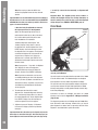
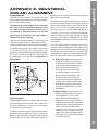
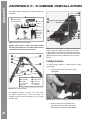
1
INSTRUCTION MANUAL 10",, 12" and 14" Advanced Coma-Free™ f/8 LX600™ with StarLock™ ® The name “Meade,” “AutoStar,”“StarLock” and the Meade logo are trademarks registered with the U.S. Patent and Trademark Office and in principal countries throughout the world. Deep Sky Imager,” “LX600,” and “Tonight’s Best” are trademarks of Meade Instruments Corp. Protected by U.S. Patent: US 6,392,799 and other Patents Pending. © 2013 Meade Instruments Corp. WARNING! Never use a Meade® LX600 Telescope to look at the Sun! Looking at or near the Sun will cause instant and irreversible damage to your eye. Eye damage is often painless, so there is no warning to the observer that damage has occurred until it is too late. Do not point the telescope at or near the Sun. Do not look through the telescope or Finder Scope as it is moving. Children should always have adult supervision while observing. TRAVEL SCREW The LX600 f/8 ACF optical tube assembly (OTA) is shipped from the factory with the focusing mechanism protected by a travel screw. This screw secures the primary mirror in a fixed position during travel thereby protecting the focusing mechanism from shock damage. This screw is on the back cell of the OTA, near the focus knob, and is identified by a dab of red paint. This screw must be removed before attempting to focus the OTA. Failure in removal can result in damage to the focusing mechanism. Retain this screw for future use as it is suggested that mirror be locked down anytime the OTA is shipped. Move the primary mirror to the travel position by rotating the focus knob counter clockwise until its travel limit is reached. Reattach the travel screw and tighten until firm. Do not over tighten. Battery Safety Instructions • Always purchase the correct size and grade of battery most suitable for the intended use. • Always replace the whole set of batteries at one time, taking care not to mix old and new ones, or batteries of different types. • Clean the battery contacts and also those of the device prior to battery installation. • Ensure the batteries are installed correctly with regard to polarity (+ and -). • Remove batteries from equipment which is not to be used for an extended period of time. • Remove used batteries promptly. • Never attempt to recharge primary batteries as this may cause leakage, fire, or explosion. • Never short-circuit batteries as this may lead to high temperatures, leakage, or explosion. • Never heat batteries in order to revive them. • Remember to switch off devices after use. • Keep batteries out of the reach of children; small batteries may be ingested. • Seek medical advice immediately if a battery has been swallowed. CONTENTS Introduction The LX600 Telescope . . . . . . . . . . . . . . . . . . . . . . . . . . . 5 Quick Start . . . . . . . . . . . . . . . . . . . . . . . . . . . . . . . . . . . . . . 6 LX600 Features . . . . . . . . . . . . . . . . . . . . . . . . . . . . . . . . . 10 AutoStar II Features . . . . . . . . . . . . . . . . . . . . . . . . . . . . . 14 Getting Started Parts Listing . . . . . . . . . . . . . . . . . . . . . . . . . . . . . . . . . 17 How To Assemble Your Telescope . . . . . . . . . . . . . . . . . 17 Choosing An Eyepiece. . . . . . . . . . . . . . . . . . . . . . . . . . 19 Observing Observing Using AutoStar II’s Arrow Keys . . . . . . . . . . . 20 Slew Speeds. . . . . . . . . . . . . . . . . . . . . . . . . . . . . . . . . 20 Astronomical Observing . . . . . . . . . . . . . . . . . . . . . . . . 20 To Track An Object Automatically . . . . . . . . . . . . . . . . . 20 Moving Through AutoStar II’s Menus. . . . . . . . . . . . . . . 21 Automatic Alignment for Alt-Az Mounted Telescopes . . 21 One-star Polar Alignment . . . . . . . . . . . . . . . . . . . . . . . 23 Syncing Your Eyepiece or Camera Using StarLock. . . . . 23 Observe a Star Using the Automatic Feature . . . . . . . . . 24 Calibrate Home . . . . . . . . . . . . . . . . . . . . . . . . . . . . . . . 24 StarLock Operation. . . . . . . . . . . . . . . . . . . . . . . . . . . . 25 Focusers. . . . . . . . . . . . . . . . . . . . . . . . . . . . . . . . . . . . 25 Cameras . . . . . . . . . . . . . . . . . . . . . . . . . . . . . . . . . . . . 25 GoTo Saturn . . . . . . . . . . . . . . . . . . . . . . . . . . . . . . . . . 25 Using the Guided Tour. . . . . . . . . . . . . . . . . . . . . . . . . . 25 AutoStar II Operation The AutoStar II Handbox . . . . . . . . . . . . . . . . . . . . . . . . 27 AutoStar Navigation Exercise . . . . . . . . . . . . . . . . . . . . 28 Example of Locating a Menu. . . . . . . . . . . . . . . . . . . . . 28 AutoStar II Menu Tree . . . . . . . . . . . . . . . . . . . . . . . . . . 29 Navigating AutoStar II . . . . . . . . . . . . . . . . . . . . . . . . . . 30 Object Menu . . . . . . . . . . . . . . . . . . . . . . . . . . . . . . . . . 30 Event Menu. . . . . . . . . . . . . . . . . . . . . . . . . . . . . . . . . . 31 Glossary Menu . . . . . . . . . . . . . . . . . . . . . . . . . . . . . . . 31 Utilities Menu . . . . . . . . . . . . . . . . . . . . . . . . . . . . . . . . 32 Setup Menu . . . . . . . . . . . . . . . . . . . . . . . . . . . . . . . . . 32 “Hot Button” Menu . . . . . . . . . . . . . . . . . . . . . . . . . . . . 36 StarLock Periodic Error Correction . . . . . . . . . . . . . . . . 36 Advanced Autostar II Features Adding Observing Sites . . . . . . . . . . . . . . . . . . . . . . . . . 37 Creating User Objects . . . . . . . . . . . . . . . . . . . . . . . . . . 38 Observing Satellites . . . . . . . . . . . . . . . . . . . . . . . . . . . 38 Landmarks . . . . . . . . . . . . . . . . . . . . . . . . . . . . . . . . . . . . . . 39 Identify . . . . . . . . . . . . . . . . . . . . . . . . . . . . . . . . . . . . . 40 Browse . . . . . . . . . . . . . . . . . . . . . . . . . . . . . . . . . . . . . 41 Alternate Alt-Az Alignments . . . . . . . . . . . . . . . . . . . . . 41 Easy Alignment . . . . . . . . . . . . . . . . . . . . . . . . . . . . . . . . . . . 41 Two-Star Alt-Az Alignment . . . . . . . . . . . . . . . . . . . . . . . . . . 42 One-Star Alt-Az Alignment . . . . . . . . . . . . . . . . . . . . . . 42 Polar Drift Alignment (Northern Hemisphere). . . . . . . . . 43 StarLock Automatic Rate Calibration. . . . . . . . . . . . . . . 43 Periodic Error Correction (PEC Training) . . . . . . . . . . . . 43 StarLock Assisted PEC Training . . . . . . . . . . . . . . . . . . 43 Update Menu Option . . . . . . . . . . . . . . . . . . . . . . . . . . . 43 Erase Menu Option . . . . . . . . . . . . . . . . . . . . . . . . . . . . 43 On and Off Menu Option . . . . . . . . . . . . . . . . . . . . . . . . 43 Optional Accessories . . . . . . . . . . . . . . . . . . . . . . . . . . . . . 44 Maintenance . . . . . . . . . . . . . . . . . . . . . . . . . . . . . . . . . . . . 46 Collimation . . . . . . . . . . . . . . . . . . . . . . . . . . . . . . . . . . 46 Inspecting the Optics . . . . . . . . . . . . . . . . . . . . . . . . . . 48 Gauging the Movement of the Telescope. . . . . . . . . . . . 48 Meade Customer Service . . . . . . . . . . . . . . . . . . . . . . . 48 Specifications . . . . . . . . . . . . . . . . . . . . . . . . . . . . . . . . . . . 49 Appendix A Training the Drive . . . . . . . . . . . . . . . . . . . . . . . . . . . . . 51 Appendix B StarLock Utility . . . . . . . . . . . . . . . . . . . . . . . . . . . . . . . 52 Appendix C Automatic Rate Calibration (ARC) . . . . . . . . . . . . . . . . . 54 Appendix D Split Fork Arms . . . . . . . . . . . . . . . . . . . . . . . . . . . . . . . 55 Appendix E Equatorial (Polar) Alignment . . . . . . . . . . . . . . . . . . . . . 57 Appendix F X-Wedge Installation . . . . . . . . . . . . . . . . . . . . . . . . . . . 62 Appendix G Latitude Chart. . . . . . . . . . . . . . . . . . . . . . . . . . . . . . . . 67 Appendix H Manual Drift Alignment . . . . . . . . . . . . . . . . . . . . . . . . . 68 Appendix I The Moon Menu . . . . . . . . . . . . . . . . . . . . . . . . . . . . . . 69 Appendix J Advanced Coma-Free Optical System . . . . . . . . . . . . . . 70 Recycling . . . . . . . . . . . . . . . . . . . . . . . . . . . . . . . . . . . . . . 71 Meade Warranty One Year Limited Warranty . . . . . . . . . . . . . . . Back Cover The LX600 Telescope Advanced Technology for the Astro Imager and Visual Observer Congratulations on receiving your new LX600 telescope. You’ll find that this telescope system has all you need to explore the Universe we live in. Drawing on over 40 years of experience and innovation, Meade Instruments introduces the latest in a long line of advanced astronomical products: the LX600. Using revolutionary new technology, every aspect of this amazing telescope system has been designed to deliver the new standard in astrophotographic and visual performance: Introduction INTRODUCTION • StarLock™ full-time automatic integrated guider assists with ultra-precise polar alignment, finds and centers targets and then automatically locks onto a field star as faint as 11th magnitude for down to one arcsecond guiding. No separate computer, no guide star selection, no user focus. Just set up your camera and image. • Fast f/8 Advanced Coma-Free (ACF) optical systems on the 10", 12" and 14" OTAs. These optics produce wider, flatter fields with no coma for pinpoint stars out to the edge of larger imaging sensors or extreme wide angle eyepieces. • Internal Crayford-style primary mirror focusing system with a dual speed 7:1 focus control, which eliminates image shift and mirror flop. Precise focus is a snap. • Optional X-Wedge is made from machined aluminum and stainless steel for 30% more stability. Configures the LX600 telescope in the Polar mode which is essential for long exposure astro phototgraphy If you are like us, you can’t wait to get outside under a dark sky to use your new LX600 telescope. We have provided a Getting Started Guide that will get you up and running in the shortest amount of time possible. After your first experience, please sit down with this manual and read about all the advanced features that are available to you with this telescope system. We are confident that the LX600 will keep you fascinated with the Universe and entertained for many years to come. Clear Skies, The People at Meade 5 AutoStar #497Quick HANDBOX Start QUICK START It is recommended that you attach the LX600 ACF telescope to the supplied tripod for observing. Perform the telescope and AutoStar II setup indoors in the light so that you become familiar with the parts and operation before moving the telescope outside into the dark for observing. B C D I vertically, with the tripod feet down and with the tripod still fully collapsed. Grasp two of the tripod legs and, with the full weight of the tripod on the third leg, gently pull the legs apart to a fully open position (Fig. B). The spreader bar (Fig. A, 4) has been removed for shipment. Slide the spreader bar onto the threaded rod on top of the spacer that is already on the threaded rod. Position the spreader bar with the flat side facing upward (Fig. C). E H G F B Tripod Head C Threaded Rod D T-handle Tension Knob E Spreader Spacer cer F G H I Leg Lock Knobs Extension Strut Tension Hub Retaining clip (not visible) Figure A. Fully assembled tripod. Figure C. Slide the spreader onto the threaded rod. Slide the threaded rod back through the tripod head from underneath. Push the retaining clip onto the threaded rod in the depressed ring on the threaded rod (Fig. D). The Field Tripod is supplied as a completely assembled unit, except for the spreader bar (Fig. A, 4). For visual observations and short exposure astro-imaging, the drive base of the telescope’s fork mount is attached directly to the field tripod. The telescope in this way is mounted in an “Altazimuth” (“Altitude-Azimuth” or “vertical-horizontal”) format. CAUTION: “Firm feel” tightening is sufficient; over-tightening may strip the threads or damage the tripod and results in no additional strength. B How to Attach the Tripod to the Telescope Assembly. (See Appendix F for attaching the tripod to X-Wedge. ) After removing the Giant Field Tripod from its shipping carton, stand the tripod Figure D. Push the retaining clip onto the threaded rod. Move the spreader bar so that the three arms of the spreader bar are lined up with the three tripod legs. Place the entire telescope onto the top of the tripod head, and thread the rod into the central threaded hole in the bottom of the drive base of the telescope. Note: that the LX600 features split fork arms; you can now break down the telescope into easier to mount parts (see page 55 for details). Tighten the T-handle tension knob (Fig. A, 3); firm tightening of the tension knob is sufficient to result in rigid positioning of the tripod legs. It is not necessary to use extreme force in tightening this knob. To vary the tripod height, loosen the six leg lock knobs and slide the three inner tripod leg sections out to the desired height. Retighten the lock knobs to a firm feel (Fig. E). 6 Figure B. Extend the tripod legs out. Qucik Start On/Off switch HBX port Lock knobs Figure E. Loosen the leg lock knobs, extend the lower portion of the leg and tighten the knobs (turn to a firm fit). To collapse the tripod (after removing the telescope), rotate the spreader bar 60° from its assembled position, so that one spreader bar arm is located between each adjacent pair of tripod legs. At the base of the tripod is a three-vane extension strut system, with a circular hub at its center (Fig. A, 7). Grasp the tripod head (Fig. A, 1) with one hand and, with the other hand, pull directly “up” on the central hub of the extension strut system. This operation will cause the tripod legs to move inward to a collapsed position. CAUTION: If the tripod does not seem to extend or collapse easily, do not force the tripod legs in or out. By following the instructions above, the tripod will function properly, but if you are unclear on the proper procedure, forcing the tripod into an incorrect position may damage the extension strut system. C Remove the covers of the battery compartments located on the fork arms (one on each fork arm) and carefully lift the battery holders from their compartments, being mindful of the connector wires. Insert four (user-supplied) C-cell batteries into each battery holder, oriented as shown on the diagram on the battery holder. Return the battery holders to their respective compartments. Replace the covers when you are done. Battery compartment Figure G. The LX600 control panel). E Remove the travel screw on the rear OTA Use the provided hex key to remove the travel screw (the position of the travel screw will vary by OTA model) (Fig. H). DO NOT OPERATE THE FOCUS KNOB BEFORE REMOVING THE SCREW or you will damage your telescope. Place the provided black plastic cap in the hole left by the travel screw. Retain the travel screw for use in future shipments. Travel screw Figure H. Remove the travel screw before operating the focuser. Return the travel screw before shipping the telescope. F Attach the 1.25" Diagonal Remove the dust cap from the rear cell of the telescope. Thread the eyepiece holder into the rear cell thread. Slide the diagonal prism into the eyepiece holder and lock in place by turning the thumbscrew to a firm feel. Place the Super Plössl 26mm eyepiece into the diagonal prism and tighten the attachment thumbscrew to a firm feel only. G Attach the Microfocuser (Optional Accessory) Remove Eyepiece Figure F. The battery compartments are located on inside of each of the fork arms. D Press the computer control panel power switch to OFF, if necessary. Remove the AutoStar II handbox and the AutoStar II coil cord from the packing materials. Plug one end into the HBX port of the telescope’s computer control panel (Fig. G) and plug the other end into the coil cord port on the AutoStar II handbox. Thumbscrews Diagonal prism Rear cell port 7 AutoStar #497Quick HANDBOX Start the dust cap from the rear cell port (A) of the telescope (Note: Telescope not shown for clarity). Thread the microfocuser adapter (B) into the rear cell port thread. Slide the microfocuser (C) over the microfocuser adapter and tighten the three hex screws on the microfocuser (K) using the provided hex keys. 훿 훾 훽 I Attach the StarLock cable. The StarLock cable has a small connector on one end and a larger connector on the other end. Plug the smaller connector into the“StarLock Telescope Connection” port on the StarLock unit and the larger connector into the “StarLock” port located on the fork arm. OR Fork arm jumper cable — other end is obscured Fork arm jumper Figure I. Attaching the optional microfocuser. 1.25" Diagonal Prism Users: If using the 1.25" diagonal prism (G), slide the 1.25" adapter (D) into the microfocuser. Line up the thumbscrew into the groove in the microfocuser. Slide the 1.25" diagonal prism into the adapter (D). Tighten the adapter thumbscrew (H) to a firm feel only. Tighten the microfocuser thumbscrews (I) to a firm feel only. 2.0" Diagonal Mirror Users: If using the optional 2.0" diagonal mirror, slide the mirror directly into the microfocuser (C). Tighten the microfocuser thumbscrews (I) to a firm feel only. J Connect the two (2) jumper cables that bridge the OTA and the telescope base. These jumpers are non-directional and identical on each fork arm. Secure the connectors to the receptacle by tightening the knobs on both sides of the plug. Finger tight, do not over tighten. 1) Remove the dust covers from the ends of the telescope tube and the narrow and wide angle tubes of the StarLock. 1! Mount and align the viewfinder. To assemble and align the viewfinder perform the following during the daytime: Dovetail bracket Retaining R e bolts H Attach the StarLock assembly. Loosen the two retaining bolts on the StarLock dovetail bracket with the provided hex key. Slide the StarLock unit fully into the saddle plate. Tighten the retaining bolts to a firm feel only. 8 1. Assemble the viewfinder by attaching all included thumbscrews onto the viewfinder bracket and insert the 8X50 viewfinder into the bracket. Tighten the thumbscrews to a firm feel only so the 8x50 optical tube is roughly centered in the middle of the bracket. 2 . Slide the viewfinder bracket into its mounting assembly on the OTA. To secure the viewfinder to the mounting assembly, tighten the two thumbscrews to a firm feel only. Remove the viewfinder dust cover. 3. Loosen the RA and DEC clutches. Point the telescope at some well-defined and stationary land object at least 200 yards distant, such as Depending on the optional accessories you attach, additional weights may need to be purchased. C 1# Tighten, to a firm feel only, the RA and DEC locks. 1$ Press the Power Switch on the computer control panel to the ON position. The copyright message lights on AutoStar II’s LCD display. RA lock DEC C lock Figure J. The RA and DEC locks. the top of a telephone pole or street sign. Center the object in the telescope eyepiece. Re-tighten the RA and DEC clutches. 4. With the object centered in the telescope eyepiece, look through the viewfinder and loosen or tighten, as appropriate, one or more of the viewfinder collimation screws until the viewfinder crosshairs are precisely centered on the object you previously centered in the telescope eyepiece. Twist the rear section near the eyecup clockwise or counter-clockwise to bring the object into clear focus. Quick Start B 1% “Press 0 to Align or Mode for Menu” displays. You can use the Arrow keys to slew (move) the telescope up, down, right, or left. To change the telescope’s slew speed, press the Speed key and then the Number keys. “9” is the fastest speed and “1” is the slowest speed. See page 20 for more details, or you can Press “0” to begin Automatic Alignment. See page 21 for more information. 5. Check this alignment on a celestial object, such as the Moon or a bright star, and make any necessary refinements. 1@ Balance the OTA. Rotate the OTA so that it is parallel to the ground plane. Locate the counterweight (Fig. K, 3) and loosen its locking hex screw just enough so that the counterweight can B Counterweight rail C Counterweight hex screw D Counterweight Figure K. OTA counterweight assembly. slide easily along the counterweight rail. While maintaining a hold on the OTA, lightly loosen the DEC Lock (Fig.J, 2) so that the OTA rotates freely. With your free hand move the counterweight until the OTA balances; favoring neither front nor back. Tighten the counter weight hex screw to secure. Note that the counterweight provides adjustment to balance the OTA equipped with the standard factory accessories. 9 AutoStar LX600 #497 HANDBOX Features LX600 FEATURES B C D E F G H I J 1) 1! 1@ 3! 3( 2$ 1( 1* 1& 1^ (Not shown) 1$ 1# (Not shown) hown)) (Not shown) 훽 훿 훾 B Eyepiece C Eyepiece thumbscrew D 1.25" diagonal prism E Diagonal prism thumbscrew F Rear cell port G Two-speed focus knob H Fork arms I Battery compartments j Travel screw Figure 1(a): LX600 Key Features - Right View; Control panel (inset) 10 1) RA slow-motion control 1! RA setting circle 1@ RA lock 1# Computer Control Panel (see page 12 for more information) 1$ Autostar II holder 1% Fork handles 1^ DEC slow-motion control 1& DEC lock 1* Dust cover 2) 2! 2@ 2% 3^ LX600 Features 2( 3) 2# 2^ 2& 2* 3& 1% 3( 3% 1( Optical tube (see page 10) 2) DEC setting circle 2! Viewfinder collimation screws 2@ 8 x 50 viewfinder 2# GPS receiver 2$ Tube adapters (see page 10) 2% Counterweight(s) 2^ Counterweight hex screw 2& Counterweight rail 3* 2* AutoStar II handbox 2( StarLock assembly 3) StarLock dovetail bracket 3! StarLock retaining bolts (see page 10) 3@ Threaded rod 3# Spreader bar 3$ T-handle tension knob 3% X-Wedge (see Appendix F) 3^ Fork Arm Jumper Cables 3& Fork Arm Connecting Plates 3* Connecting Plate Bolts (4 per 3@ 3# 3$ fork arm) 3( StarLock Cable Figure 1(b): LX600 Key Features - Left View 11 AutoStar LX600 #497 HANDBOX Features LX600 FEATURES The Meade LX600 ACF models are extremely versatile, highperformance telescopes for imaging and visual use. With pushbutton controls, precision GPS alignment, true-level and North electronic sensors, StarLock automatic guiding and ultraprecise pointing, automatic tracking of celestial objects, and a library of 145,000+ objects in the AutoStar II database, the LX600 ACF models offer unmatched state-of-the-art performance. Caution: Do not operate the RA or DEC slow-motion controls with the locks in the fully locked position, as such operation may result in damage to the internal gear system and also cause you to lose alignment. Observe or image the rings of the planet Saturn from a distance of 800 million miles or focus beyond the Solar System on ancient star clusters, remote galaxies, and stars recently discovered to have planets orbiting about them. Meade LX600 ACF telescopes are capable of growing with your interest and can meet the requirements of the most demanding advanced observer. rotation of the telescope. Turning the RA lock counterclockwise unlocks the telescope, enabling it to be freely rotated by hand about the horizontal axis. Turning the RA lock clockwise locks the telescope, prevents the telescope from being rotated manually, and engages the horizontal motor drive for AutoStar II operation. Caution: Using products other than standard Meade accessories may cause damage to the telescope’s internal electronics and may void the Meade warranty. B Eyepiece: Place the Series 4000 26mm Plössl eyepiece into the 90° diagonal prism (Pg. 10, Fig. 1, 1) and tighten in place with the eyepiece thumbscrew (Fig. 1, 2). The eyepiece magnifies the image collected in the optical tube. C Eyepiece Thumbscrew: Tightens the eyepiece (Fig. 1, 2) in place. Tighten to a firm feel only. D 1.25" Diagonal Prism: Provides a more comfortable right angle viewing position. E Diagonal Prism Thumbscrew: Tightens the diagonal prism in place. Tighten to a firm feel only. F Rear Cell Port: The diagonal prism slides into this port. G Two-speed Focus Knob: 2-Speed Crayford-style focusing system moves the telescope’s primary mirror in a finely-controlled motion to achieve precise image focus. LX600 telescopes can be focused on objects from a distance of about 100 ft to infinity. Rotate the focus knob clockwise to focus on distant object. H Fork Arms: This heavy-duty mount holds the optical tube securely in place. I Battery Compartments: Insert four user-supplied C-cell batteries into each compartment (one compartment on each fork arm; eight batteries total). J Travel Screw: Locks down the primary mirror during transportation. 1) Right Ascension (RA) Slow-Motion Control: When not using AutoStar electronic control, make fine adjustments in the Right Ascension, i.e. the horizontal axis, by turning this control with the RA lock in the unlocked position. Set the RA lock to a “partially locked” position to create a comfortable drag for the RA slow-motion control. 12 1! Right Ascension (RA) Setting Circle: See Appendix E, page 57, for detailed information. 1@ Right Ascension (RA) Lock: Controls the manual horizontal 1# Computer Control Panel (see Pg. 10, Fig. 1 inset): A. ON/OFF Switch: Turns the computer control panel and AutoStar II ON or OFF. The red power indicator LED next to the switch illuminates when power is supplied to the AutoStar II handbox, the optional microfocuser and to the telescope’s motor drives (the LED can be turned off in the Panel Light menu; see page 32). B. 12vDC Power Connector: Provides a connection so that the telescope assembly may be powered from a standard 115/240v AC home outlet using the optional Universal Power Adapter (product# 07584) or the optional 12v DC #607 Cigarette Lighter Adapter (product# 07043). See Optional Accessories, page 44. C. Focus Port: (An additional focus port is located on the fork arm). Plug the optional microfocuser into this port. Control the microfocuser through the AutoStar II menus. See Hot Button Menus, page 36. D. Reticle Port: Plug the optional reticle eyepiece cable into this port. Control the reticle through the AutoStar II menus. See Hot Button Menus page 36. Also see OPTIONAL ACCESSORIES, page 44. Note: See the instruction sheets that are included with the focuser and the reticle for more details. E. 12vDC Output: (An additional 12vDC power output is located on the fork arm) Use the 12vDC output to power telescope accessories. F. Handbox (HBX) Port: Plug the AutoStar II coil cord into this port. G. RS232 Port: Provides a connection with a PC H. Auxillary Autoguider Port: If you wish to use an add-on autoguider in place of the integrated StarLock, plug the autoguider cable into this port. See the instruction sheet that came with your autoguider for more information. the telescope eyepiece. 2# GPS Receiver: Receives information transmitted from Global Positioning System satellites. See page 24 for more information. 2$ Tube Adapters: The optical and mechanical axes of the LX600 telescope have been carefully aligned at the factory to ensure accurate object pointing. Do not loosen or remove the optical tube assembly from the tube adapters. The resulting misalignment of the axes will result in inaccurate pointing of the telescope in the GO TO mode. below) or X-Wedge. Holds your handbox in a convenient location. 2% StarLock Counterweight(s): Precisely counter balance the StarLock assembly and optional accessories by moving this weight. 1% Fork Handles: Use to lift optical tube assembly or to rotate 2^ StarLock Counterweight Hex Screws: Tighten to secure the telescope when attached to the tripod. the counterweight in place. Important After the telescope is aligned do not use the RA or DEC manual slow motion controls or alignment will be lost and the telescope will need to be realigned. 2& StarLock Counterweight Rail: Slide the StarLock counterweight along this rail to achieve optimum balance. 1$ Tiltable AutoStar II Holder: Attach to fork handles (see 1% (DEC) Slow-Motion Control: Make fine adjustments in declination (altitude) by turning this control. In order for this control to operate properly, power must be off. 2* AutoStar II Handbox: The LX600 user interface. Use the Handbox to command the LX600 to automatically slew to any object in the night sky. See pages 27 thru 36 for a description of features. 1& DEC 2( StarLock 1^ Declination Lock: Controls the manual vertical movement of the telescope. Turning the DEC lock counterclockwise unlocks the telescope, enabling it to be freely rotated by hand about the vertical axis. Turning the DEC lock clockwise (to a firm feel only) prevents the telescope from being moved manually, but engages the vertical motor drive for AutoStar II operation. Assembly: Integrated autoguiding unit made up of the StarLock narrowfield OTA and sensor, used for highprecision guiding, and the StarLock widefield OTA and sensor, used in alignment and ultra-precise pointing. Caution: When loosening the DEC lock, be sure to support the optical tube (Fig. 1, 19). The weight of the tube could cause the tube to swing through the fork arms suddenly. 3! StarLock Retaining Bolts: Secures the StarLock assembly to the dovetail adapter. 1* Dust Cover: Gently pry the dust cover from the front lens of Threaded Rod: Secures the LX600 mount to the the telescope. Note: The dust cover should be replaced after each observing session and the power turned off to the telescope. Verify that any dew that might have collected during the observing session has evaporated prior to replacing the dust cover. 1( Optical LX600 Features and for current and future Meade accessories. Your PC can control your LX600 ACF telescope using the supplied AutoStar Suite software for custom applications. Go to the Meade website (www.meade.com) to download the latest serial commands and device pinouts. 3) StarLock Dovetail Adapter: Attaches StarLock to the telescope mount. 3@ Tripod tripod. 3# Tripod Spreader Bar: Holds the LX600 mount and tripod legs in place. 3$ Tripod T-handle Tension Knob: Use to apply tension to the tripod spreader bar. 3% X-Wedge: See Appendix F for details. 3^ Fork Arm Jumper Connector: Bridges the break between Tube: The main optical component that gathers the light from distant objects and brings this light to a focus for examination through the eyepiece. OTA and Telescope base. 2) Declination (DEC) Setting Circle: See Appendix E, page 57, for detailed information. 3& Fork Arm Connecting Plate: Mates OTA to base for easier assembly. Four connecting screws per side(See Appendix D). 2! Viewfinder Collimation Screws: Use these six screws to 3* Connecting Plate Bolt: Used to secure the OTA to Telescope adjust the alignment of the viewfinder. 2@ 8 x 50mm Viewfinder: A low-power, wide-field sighting scope with crosshairs that enables easy centering of objects in base. Four (4) connecting screws per side. 13 AutoStar #497IIHANDBOX AutoStar Features AUTOSTAR II FEATURES 1! Library Number of Objects New General Catalog (NGC) ........................ 7,840 Index Catalog (IC)........................................5,386 B Messier Catalog (M)........................................110 Caldwell Catalog ............................................ 109 C D F E Named Objects ..............................................227 Herschel Catalog ...........................................400 Abell Catalog of Galaxy Clusters ................. 2,712 Arp Catalog of Irregular Galaxies ...................645 Uppsala Galaxy Catalog ............................ 12,940 Morphological Catalog of Galaxies ............ 12,939 G General Catalog of Variable Stars .............28,484 I SAO ........................................................... 17,191 Hipparcos Star Catalog ..............................17,325 J 1) H Figure 2: The AutoStar II handbox Tour the Cosmos with Just the Push of a Button Control of the LX600 ACF telescope models is through the operation of the standard AutoStar II system. Nearly all functions of the telescope are accomplished with just a few pushes of AutoStar II’s buttons. Because the AutoStar II system uses flash (rewritable) memory, your system will be able to grow when new features and enhancements become available. Download the latest satellite data, star and object catalogs, tours, serial commands list and software revisions, directly from the Meade website (www. meade.com). To learn about downloading updates see Page 35. Requires the optional #507 Cable Connector Kit (product# 07047. See OPTIONAL ACCESSORIES, page 44). Some of the major features of the AutoStar II system are: ■ 14 Automatically move the telescope to any of the more than 145,000 objects stored in the object library, including: ■ Take a guided tour of the best celestial objects to view on any given night of the year. ■ Control your LX600 ACF with your PC using an RS232 interface. ■ Align your telescope automatically using GPS (Global Positioning System), Level North sensors and StarLock. ■ Access a glossary of astronomical terms. ■ Mount the telescope in the “Alt-az” mode (altitude-azimuth, or vertical-horizontal), or polar mode with the optional X-Wedge, for fully automatic tracking, GoTo pointing and guiding on celestial objects. The AutoStar II system provides control of virtually every telescope function. The AutoStar II handbox has soft-touch keys designed to have a positive feel. The LCD (Liquid Crystal Display) is backlit with red LEDs (Light Emitting Diodes) for easy viewing in the dark. The backlit display, key arrangement, and sequential menu structure make AutoStar II extremely user friendly. B 2-Line LCD Display: This screen displays AutoStar II’s menus and information about the telescope. • Top line: Lists the primary menu. • Bottom line: Displays other menus that may be chosen, menu options, telescope status, or information about a function that is being performed. an option in a menu. The ENTER key is similar to the RETURN or ENTER key on a computer. See NAVIGATING AUTOSTAR II, page 30 and AutoStar II Menu Tree, page 29. d MODE Key: Press to return to the previous menu or data level. The top menu level is “Select Item”. The MODE key is similar to the ESCAPE key on a computer. Additionally, use the Arrow keys to to move the cursor across the display: Use the Right or Left Arrow key (Fig. 2, 5) to move the cursor from one number to the next in the display. g Number Keys: Press to input digits 0 to 9. Each Number key also has a specific function, which is printed on each key (these are commonly known as “hot buttons”—see page 36): 1 SPEED: Changes the slew speeds. To operate, press Speed and then a Number key (1 is the slowest speed, 9 is highest speed). To learn about changing slew speed see Page 20. Note: Pressing MODE repeatedly while in the “Select Item” level moves AutoStar II to the topmost screen: “Select Item: Object”. 2 CALD (Caldwell): Press to display the Caldwell catalog on the AutoStar II handbox. Note: If MODE is pressed and held for two seconds or more, information about the telescope’s status displays. When the status displays, press the Scroll keys (Fig. 2, 7) to display the following information: 3 M (Messier): Press to display the Messier catalog library. 4 Focus: Press to display the Focus Control menu. • Right Ascension and Declination (astronomical) coordinates 5 SS: Press to display the Solar System library. 6 STAR: Press to display the Star library. • Altitude (vertical) and Azimuth (horizontal) coordinates 7 RET (Reticle): Press to display the StarLock Control menu. To learn about the StarLock menu see Page 32. • Local Time and Local Sidereal Time (LST) • Timer and Alarm Status 8 IC: Press to display the Index Catalog library. • Date 9 NGC (New General Catalog): Press to display the NGC catalog library. • Site coordinates • Battery status 0 LIGHT: Press to turn on and off the red utility light on the top of the hand-box. Press MODE again to return to the previous menu. e GO TO Key: Press to slew (move) the telescope to the coordinates of the currently selected object. While the telescope is slewing, the operation may be aborted at any time by pressing any key except GO TO. Pressing GO TO again resumes the slew to the object. Also, press during the alignment or GO TO procedures to activate a “spiral search”. To learn more about the GO TO function and performing a spiral search see Page 23. f Arrow Keys: The Arrow keys have several functions. Press an Arrow key to slew the telescope in a specific direction (up, down, left, and right), at any one of nine different speeds. See Slew Speeds, page 20. Use the Up and Down Arrow keys to move the telescope vertically up and down. The Left Arrow key rotates the telescope horizontally counterclockwise, while the Right Arrow key rotates it clockwise (unless reversed for Southern Hemisphere use). Also, use the Arrow keys to scroll through numbers 0 through 9 and the alphabet. The Down Arrow key begins with the letter “A”, the Up Arrow key begins with digit “9”. AutoStar II Features c ENTER Key: Press to go to the next menu level or to choose h Scroll Keys: Press to access options within a selected menu. The menu is displayed on the first line of the screen. Options in the menu are displayed, one at a time, on the second line. Press the Scroll keys to move through the options. Press and hold a Scroll key to move quickly through the options. The Scroll keys also control the speed of text scrolling on the AutoStar II display. When text is scrolling, press and hold the Up Scroll key for a faster display speed and the Down Scroll key for a slower display speed. i? Key: Press to access the “Help” file. “Help” provides on-screen information on how to accomplish whatever task is currently active. Press the ? key and then follow the prompts on the display to access details of AutoStar II functions in the Help feature. The Help system is essentially an on-screen instruction manual. If you have a question about an AutoStar II operation, e.g., INITIALIZATION, ALIGNMENT, etc., press the ? key and follow 15 AutoStar #497IIHANDBOX AutoStar Features the directions that scroll on the second line. When satisfied with the Help provided, press MODE to return to the original screen and continue with the chosen procedure. Tip: When an astronomical term appears in [brackets], press ENTER for a definition or more detailed information. Press MODE to return to the scrolling AutoStar II Help display. If a celestial object’s name appears in brackets (and your telescope is aligned), press ENTER and then GO TO to slew the telescope to the object. j Coil Cord Port: Plug one end of the AutoStar II coil cord (Pg. 14, Fig. 2, 10) into this port located at the bottom of the AutoStar II handbox. 1) Coil Cord: Plug one end of the AutoStar II coil cord into the HBX port (Pg 10, Fig 1 inset, F) of the computer control panel of the telescope and the other end into the AutoStar II coil cord port. See #9 above. 1! Utility Light: Use this built-in red light to illuminate star charts and accessories without disturbing your eye’s adaptation to darkness. Press “0” to turn the light on and off. 16 Parts Listing replace the covers.) 3. Plug in the AutoStar II handbox: Be certain that the power switch on the computer control panel (Fig. 1, 13A) is in the OFF position. Plug the coil cord of the AutoStar II handbox into the HBX port (Fig. 1, 13F). Getting the telescope ready for first light requires only a few minutes. When first opening the packing box, note carefully the following parts: ■ LX600 ACF telescope with fork mount system ■ AutoStar II handbox and interface coil cord; handbox holder ■ 8 x 50mm viewfinder assembly ■ Eyepiece holder and 1.25" diagonal prism ■ Series 4000 26mm Super Plössl eyepiece ■ OTA Counterweight(s) ■ DEC Jumper cables (2) ■ Anti-vibration pads (3) ■ 507 Connecting Cable ■ Variable height Giant Field Tripod and mounting base, threaded rod with T-handle tension knob, spacer cone and c-clip, and spreader bar ■ Set of hex keys ■ StarLock unit with cable ■ Instructional Manual and Software DVD. Note: The AutoStar II handbox does not require batteries. The telescope supplies its power. 4. Remove the dust cap from the rear cell of the telescope. Thread the eyepiece holder into the rear cell thread. Slide the diagonal prism into the eyepiece holder and lock in place by turning the thumbscrew to a firm feel. 5. Insert eyepiece: Remove the Series 4000 26mm Super Plössl eyepiece (Fig. 1, 1) from its container and place it in the diagonal prism (Fig. 1, 3). Tighten the eyepiece holder thumbscrew (Fig. 1, 2) to a firm feel only. 6. Remove the travel screw. The LX600 is shipped with a travel screw in place to protect the primary mirror during shipping. Use the provided hex key to remove the screw. Replace the screw with the provided plastic cap. DO NOT ADJUST THE FOCUS KNOB BEFORE REMOVING THE TRAVEL SCREW OR DAMAGE TO YOUR TELESCOPE WILL OCCUR. How to Assemble Your Telescope Assembly of the LX600 ACF telescope requires eight C-cell (usersupplied) batteries or the optional Universal AC Power Adapter (product# 07584) connected to a standard 115v home outlet or to an optional #607 Cigarette Lighter Adapter (see OPTIONAL ACCESSORIES, page 44). Plug an adapter into the 12vDC In port of the computer control panel (Fig. 1, 13B). 7. Remove dust cover: Remove the dust cover (Fig. 1, 18) from the optical tube assembly (Fig. 1, 19) by gently prying it off. Note that the LX600 features split fork arms allowing you the option of breaking the telescope down into to two, easier to maneuver units. See Appendix D, Page 55 for details. 1. Position the telescope: Start by turning the DEC lock (Pg. 10, Fig. 1, 17) counterclockwise to unlock the the optical tube (Fig. 1, 19). Next, move the optical tube through the fork arms to the position depicted in Fig. 1 and turn the DEC lock clockwise to a firm feel to relock the position of the optical tube. 2. Install batteries: Remove the battery compartment covers (Fig. 1, 8) and carefully remove the battery holders, being mindful of the connector wires. Insert four user-supplied C-cell batteries into each battery holder, oriented as shown on the diagram on the battery slots inside the battery holder. Return the battery holders to their respective compartments and Getting Started GETTING STARTED 8. Attach the handbox holder: Remove the handbox holder from the plastic bag. If necessary, loosen the lock knob (Fig. 3a, A) and place the clamp (Fig. 3a, B) about one of the fork arm handles (Fig. 1, 15). Tighten the lock knob to a firm feel. Slide the AutoStar II handbox into the holder (Fig. 3a, C). You may also snap the 훽 훾 훿 Figure 3a: Handbox holder: (A) Lock knob; (B) Clamp; (C) Holder. Fig. 3b: Handbox holder attached to fork arm handle. 17 AutoStar #497 HANDBOX Getting Started handbox into the holder: Slide one side of the handbox into the holder and then firmly press the other side of the handbox into the holder until it snaps in place. Adjust the tilt of of the holder by loosening the lock knob and then moving the holder clamp to the desired angle. Retighten the lock knob. GPS receiver Collimation screws Viewfinder eyepiece 9. Mounting and Adjusting the Viewfinder. To align the viewfinder, perform steps A through E below during the daytime; perform step F at night. A. Slide the track on the bottom of the viewfinder into the slot in the viewfinder mounting assembly. To secure the viewfinder to the mounting assembly, tighten the two thumbscrews (Fig. 9) to a firm feel only. B. If you have not already done so, insert the Mounting slot Track Fig. 5. Viewfinder collimation screws and eyepiece 5) until the viewfinder crosshairs are precisely centered on the object you previously centered in the telescope eyepiece. F. Check this alignment on a celestial object, such as the Moon or a bright star, and make any necessary refinements, using the method outlined in steps C through E. 10. Mounting the StarLock unit. Mount the StarLock unit by sliding it into the StarLock dovetail adapter on the top of the OTA. The unit slides into the adapter from back to front. Dovetail bracket Retaining R e bolts Thumbscrews ce s cr Viewfinder base locking screws Fig. 4. Viewfinder assembly 26mm eyepiece into the diagonal prism. C. Unlock the RA (Pg. 10, Fig. 1, 12) and DEC (Fig. 1, 17) locks so that the telescope moves freely on both axes. D. Point the telescope at some well-defined and stationary land object at least 200 yards distant, such as the top of a telephone pole or street sign. Center the object in the telescope eyepiece. Retighten the RA and DEC locks. E. Look through the viewfinder eyepiece (Fig. 5) and loosen or tighten, as appropriate, one or more of the viewfinder collimation screws (Fig. 18 Mount StarLock Once positioned, secure the unit by tightening the thumbscrews until they are snug. Do not overtighten. Remove both dustcovers from the lenses of the StarLock. 11. Attach the StarLock cable. The StarLock cable has two distinct connections, a four-pin and a six-pin. Make sure that you plug the four-pin end into the “StarLock Telescope 11. Attach the DEC jumper cable. LX600 features split fork arms. In order to make electric connection between the two portions you must install the jumper cables on the left and right sides. . Choosing an Eyepiece A telescope’s eyepiece magnifies the image formed by the telescope’s main optics. Each eyepiece has a focal length, expressed in millimeters, or “mm”. The smaller the focal length, the higher the magnification. For example: An eyepiece with a focal length of 9mm has a higher magnification than an eyepiece with a focal length of 26mm. Your telescope comes supplied with a 26mm Plössl eyepiece which gives a wide, comfortable Series 4000 26mm Super field of view with high Plössl eyepiece image resolution. Low power eyepieces offer a wide field of view, bright, highcontrast images, and eye relief during long observing sessions. To find an object with a telescope, always start with a lower power eyepiece such as the 26mm Plössl. When the object is located and centered in the eyepiece, you may wish to switch to a higher power eyepiece to enlarge the image as much as practical for prevailing seeing conditions. For information about optional eyepieces for the your telescope, see OPTIONAL ACCESSORIES, page 44. The power, or magnification of a telescope is determined by the focal length of the telescope and the focal length of the eyepiece being used (an eyepiece’s focal length is printed on the side of the eyepiece). To calculate eyepiece power, divide the telescope’s focal length by the eyepiece’s focal length. Too Much Power? Can you ever have too much power? If the type of power you’re referring to is eyepiece magnification, yes, you can! The most common mistake of the beginning observer is to “overpower” a telescope by using high magnifications which the telescope’s aperture and atmospheric conditions cannot reasonably support. Keep in mind that a smaller, but bright and well-resolved image is far superior to one that is larger, but dim and poorly resolved. Powers above 400X should be employed only under the steadiest atmospheric conditions. Getting Started Connection” port on the back of the StarLock unit, and the six-pin into the “StarLock” port on the fork arm. Jupiter; examples of the right amount of magnification (left) and too much magnification (right). AutoStar II can calculate the best eyepiece for you to use. Try out the “Eyepiece Calc” feature in the Utilities menu. Most observers should have three or four additional eyepieces to achieve the full range of reasonable magnifications possible with the LX600 ACF telescopes. See OPTIONAL ACCESSORIES, page 44. available for the LX600 ACF telescopes, see OPTIONAL ACCESSORIES, page 44. Note: Seeing conditions vary widely from night-to-night and site-to-site. Turbulence in the air, even on an apparently clear night, can distort images. If an image appears fuzzy and ill-defined, back off to a lower power eyepiece for a more well-resolved image (see above example of Jupiter). For example: A 26mm eyepiece is supplied with LX600 ACF models. The focal length of the 14" f/8 LX600 ACF is 2845mm (see Specifications, pages 49 and 50). Eyepiece Power = Telescope focal length ÷ Eyepiece focal length Eyepiece Power = 2845mm ÷ 26mm Eyepiece Power = 109 The eyepiece power, or magnification is therefore 109x. Note: For a list of magnification ratings of the eyepieces 19 AutoStar #497 Observing HANDBOX OBSERVIING Observing Using AutoStar II’s Arrow Keys Number Key 2= 2x = 2 x sidereal (0.5 arc-min/sec or 0.008°/sec) Number Key 3= 8x = 8 x sidereal (2 arc-min/sec or 0.033°/sec) 2. Verify that AutoStar II is properly connected to your telescope. See Quick Start, page 6. Number Key 4= 16x = 16 x sidereal (4 arc-min/sec or 0.067°/sec) 3. Flip the telescope power switch to the ON position. Number Key 5= 64x = 64 x sidereal (16 arc-min/sec or 0.27°/sec) The AutoStar II screen is activated and a copyright message displays briefly, followed by a short beep. Then AutoStar II takes a few moments to start up the system. Number Key 6= 128x = 30 arc-min/sec or 0.5°/sec Number Key 7= 1.5° = 90 arc-min/sec or 1.5°/sec Number Key 8= 3° = 180 arc-min/sec or 3°/sec 4. After the Autostar II has finished startup, "Press Mode for Menu or 0 to Align displays". Press Mode. Number Key 9= Max = 480 arc-min/sec or 8°/sec) You may observe land and astronomical objects using AutoStar II’s Arrow keys to move the telescope. 1. Tighten the RA and DEC locks (Fig. 1, 12 and 17). 5. Press the Mode key several times until Setup Item: Object displays. 6. The Arrow keys are now activated. Press the Arrow keys (Pg. 14, Fig. 2, 5) to slew (move) the telescope up, down, right, or left. 7. Press the Speed key (Number key “1”) and then a Number key (Fig. 2, 6) to change the telescope’s slew speed (“1” is the slowest speed, “9” is highest speed). 8. Use the viewfinder (Fig. 1 , 22) to locate an object and practice using the AutoStar II’s Arrow keys to center the object in the telescope’s field of view. Warning: Do not look through the telescope’s eyepiece or viewfinder while it is rapidly moving. Children should always have adult supervision while observing. Slew Speeds AutoStar II has nine slew speeds that move the optical tube at rates that are directly proportional to the sidereal rate and have been calculated to accomplish specific functions. Press the Speed key (Number key “1”) and then press a Number key to change the slew speed, which is shown for about two seconds on AutoStar II’s display. 20 The nine available speeds are: Number Key 1= 1x = Guide Rate, programmable Speeds 1, 2, or 3: Best used for fine centering of an object in the field of view of a higher power eyepiece, such as a 12mm or a 9mm eyepiece. Speeds 4, 5, or 6: Enable centering of an object in the field of a low-to-moderate power eyepiece, such as the standard Super Plössl 26mm. Speeds 7 or 8: Best used for rough centering of an object in the viewfinder. Speed 9: Moves the telescope quickly from one point in the sky to another. Astronomical Observing Used as an astronomical instrument, your telescope has many optical and electromechanical capabilities. It is in astronomical applications where the high level of optical performance is readily visible. The range of observable astronomical objects is limited only by the observer’s motivation. To Track an Object Automatically As the Earth rotates beneath the night sky, the stars appear to move from East to West. The speed at which the stars move is called the sidereal rate. You can setup your telescope to move at the sidereal rate so that it automatically tracks (follows) the stars and other objects in the night sky. If the telescope is not tracking an astronomical object, the object will drift out of the eyepiece field of view. The tracking function automatically keeps an object centered in the telescope’s eyepiece. To automatically track objects, you need to learn how the AutoStar II keypad operates in order to move through its menus. You will need to initialize and align your telescope. The AutoStar II database is organized in levels for quick and easy navigation. ■ Press ENTER (Pg. 10, Fig. 2, 2) to go deeper into AutoStar II’s menu levels. ■ Press MODE (Fig. 2, 3) to move back toward the top menu level. ■ Press the Scroll keys (Fig. 2, 7) to move up and down through the options available for each level. ■ Press the Arrow keys (Fig. 2, 5) to enter characters and digits. The Arrow keys are also used to move the telescope. ■ Use the Number keys (Fig. 2, 6) to enter digits. Automatic Alignment for Alt-Az Mounted Telescopes AutoStar II offers four methods of altazimuth (alt-az) alignment; this section describes how to initialize and align your telescope using Automatic Alignment. (For a description of the other altaz alignment methods, see page 41. For information about equatorial (polar) alignment, see the next section, Appendix D and Appendix E). To prepare your telescope for Automatic Alignment: 1. Tighten the RA and DEC locks (Pg. 10, Fig. 1, 12 and 17). 2. Verify that AutoStar II is properly connected to your telescope. See How To Assemble Your Telescope, page 17. 3. Flip the telescope power switch to the ON position. When you slide the On/Off switch to “On” on your telescope’s computer control panel, a version screen briefly appears, followed by “Welcome to AutoStar”. 4. “Press 0 to align or Mode for Menu” displays. Press “0” to begin Automatic Alignment. (If you wish to choose a manual alignment method, keep pressing Mode to go through the menus to find other alignments.) Note: AutoStar II initializes the Smart Drive if it has been turned “On,” has been previously selected, PEC training has been performed and you have “parked” the telescope. If you have parked it, AutoStar II will remember its position on the worm gear. If you do not park the scope and turn it off, it will not remember its position. See Parking the Telescope, page 32 and PEC Training, page 43. 5. “Automatic Alignment” displays. The system now performs the following routines (press any AutoStar II key to abort Automatic Alignment) : Observing Moving Through AutoStar II’s Menus Caution: As the telescope performs the following operations, it will swing and rotate. Keep a safe distance from the telescope. The telescope now finds the level and tilt position of the telescope, and also detects where true North is. It may not actually level or tilt the telescope or point to North — it is just detecting these positions. This may take a minute or two. a. Finds the home position. Moves the telescope to find the “home” position. When the home position is found, the system knows the limiting positions of the telescope and can avoid tangling cables and over-rotating the telescope. b. Detects “level” position of the telescope; finds tilt and tip. To detect level, AutoStar II must calculate “level” at three compass points. See Detecting True Level on page 24. AutoStar II also determines the positioning (i.e., tilt and tip) of the optical tube. c. Finds North. Locates magnetic North, then calculates true North. See Detecting True North, page 24. d. Attempts a “GPS Fix”. The GPS receiver attempts to acquire and sync up with signals from the GPS satellite system. “Getting GPS Fix” displays. See The Global Positioning System on page 24. After performing these operations, AutoStar II now knows: ■ The telescope’s limiting positions ■ Where level is for the telescope ■ The location of true North ■ The observing site’s location ■ The date and time 21 AutoStar #497 Observing HANDBOX Note: Press any key to abort the GPS fix. You will then be prompted to enter the time, date and location. Important Note: It is recommended that you do not attempt a GPS fix indoors. It is also recommended that you CALIBRATE SENSORS the first time your telescope takes a GPS fix. See page 33 for more information. e. Once the level, tilt and North are detected, the telescope will “Go To” two alignment stars. The telescope will go to these stars in order to orient itself to the sky. Once it has done this, it will be able to point to any of the more than 145,000 stars in its database. “Automatic Alignment: Selecting Star” and “Slewing” display. Finally, when it is close to the alignment star “Center Brightest Star: Press ENTER” displays. Use the Arrow keys to center the alignment star in the eyepiece. The alignment star will be the brightest star in that area of the sky (and hence, “brightest star”). When the alignment star is centered, press ENTER. This also defines the telescope’s optical center on the StarLock sensor. Note: If you press the “?” key while “Ctr Brightest Star” displays, the name of the alignment star that AutoStar has chosen will display. For example, “Arcturus: Press ENTER” may display. Note: If you have an obstruction, such as a tree or a building blocking your view of the alignment star, or if you have any doubts at all about the star that has been chosen, no problem. Just press the Scroll Down key and AutoStar will find another star to align upon. 6. The telescope now slews to the second alignment star. “Automatic Alignment: Selecting Star” and “Slewing” display. When it is close to the second alignment star “Center Brightest Star: Press ENTER” displays. Use the Arrow keys to center the alignment star in the eyepiece. 7. “Alignment successful” displays. If “Alignment Unsuccessful” displays, perform the procedure over again. Important Note: Once the telescope is aligned, only use the Arrow keys to move the telescope. Once the telescope has been aligned, do not loosen the telescope locks (Pg. 10, Fig. 22 1, 12 and 17), or move the base manually, or alignment will be lost. Important Note: The Daylight Saving menu enables or disables the Daylight Savings Time setting: Remember to turn this setting off or on the two days a year when Daylight Saving changes. See TIMING IS EVERYTHING, page 35. Polar Mode Pointing at Polaris North The LX600 in proper orientation for one-star polar alignment Up until this point we have described the operation of the LX600 in the Alt-Azmuth mode. The LX600 telescope was designed to be operated in the Polar mode using Meade’s X-Wedge. This precision machined, rigid equatorial wedge is designed to securely mount between the giant field tripod and the LX600 telescope and provides a steady platform ideally suited for long term astro photography. Instructions to attach the X-Wedge and mount the LX600 telescope can be found in Appendix F: X-Wedge Installation (Page 62-66). The alignment procedure for an X-Wedge mounted LX600 differs from Alt-Azmuth mode telescope. Meade offers you several polar alignments to choose from, but generally “One-Star Polar Alignment” described below is preferred method. One-star Polar Alignment Setup the telescope facing true North with the tripod level. Use the altitude adjustment knob on the X-Wedge to set your latitude. Make sure the telescope is set to Polar mode in the Autostar Setup/Telescope/Mount Menu (See page 32). Turn on the power to the telescope and when the AutoStar II handbox displays "Press 0 to Align, Mode for Menu", press "0". The AutoStar II will ask you to place the telescope in the polar home position. Polar home position is where the DEC axis is at 90 degrees (telescope tube pointing directly away from the drive base and parallel to the fork arms) and the RA axis is at 0:00 hour angle (rotate the RA axis to put the viewfinder on the underside of the telescope tube and the base of the fork arms is parallel to the ground). Press "ENTER" and the telescope will get GPS time, date and location, and will then slew near to the star Polaris. Find Polaris in the viewfinder (it is very important to have the viewfinder aligned with the optics of your telescope. See page 18) and using the azimuth and altitude controls on the X-Wedge, center Polaris on the crosshairs of the viewfinder. Now, look through a low power eyepiece like the 26mm Super Plössl and further adjust the X-Wedge controls until Polaris is accurately centered in the field of view. Relock the X-Wedge locking screws. Press "ENTER" to confirm and the telescope will slew to a second star. Using the AutoStar II handbox slew keys, center the star in the viewfinder and then accurately center it in the eyepiece. Press "ENTER" and the alignment is complete. Tip: To manually enter the RA and DEC coordinates of an object: Press and hold MODE for two seconds or more. The RA and DEC coordinates display. Press GO TO. “Object Position” and a set of coordinates displays. Then enter the RA and DEC coordinates of any celestial object using Number keys. As soon as the coordinates are entered, AutoStar II slews the telescope to the coordinates. Note that the telescope must be initialized for this procedure to operate properly. Which One’s the Alignment Star? If AutoStar II has chosen an alignment star with which you are unfamiliar, how can you be sure if the star in your eyepiece is really the alignment star? The rule of thumb is that an alignment star is usually the brightest star in that area of the sky. If you perform a GO TO to an alignment star and you’re not sure if you have located the alignment star or it isn’t in the eyepiece, look through your viewfinder. When you view an alignment star in the viewfinder, it stands out dramatically from the rest of the stars in that portion of the sky. The viewfinder will help you locate a star more quickly than the eyepiece, because it has a much wider field of view than the eyepiece. Using AutoStar II, set the slew speed to 6 or higher and use the Arrow keys to center the alignment star in the viewfinder. If your viewfinder has been aligned with the telescope, the alignment star should now be in the eyepiece. Set the slew speed to 4 or less and center the star in the eyepiece. Observing Tip: The GO TO key also allows you to perform a “spiral search”. A spiral search is useful when the telescope slews to an object, but that object is not visible in the eyepiece after the telescope finishes its search. (This sometimes occurs during an alignment procedure.) Press GO TO when the telescope stops slewing. The telescope begins to move in a spiral pattern at a very slow speed around the search area. Look through the eyepiece and when the object does become visible, press MODE to stop the spiral search. Then use the Arrow keys to center the object. Syncing your Eyepiece or Camera using Starlock Whenever you change eyepieces, diagonals or cameras, the center field of view may shift slightly. Starlock can compensate for this slight difference by performing the following routine: 1. Press the MODE key several times, until “Select Item: Object” is displayed. 2. Press the ENTER key to choose the “Object” option and move down four (4) levels. “Object: Star” is displayed. 3. Press the ENTER key to choose the “Star” option and move down one (1) level. “Named” is displayed. 3. Press the ENTER key to choose the “Named” option. 4. Scroll thorough the lists of Named star until you come to a bright star that is visible (if you are not sure what to choose use the same star that AutoStar used during the alignment procedure). Press the GOTO key to choose that star. 5. The telescope will slew to that star. When slewing has been completed, re-center the star in the eyepiece or camera. Then hold the “ENTER” key for 2 seconds. Then press “ENTER” again to confirm your position. StarLock will now compensate for the offset. 23 AutoStar #497 Observing HANDBOX Calibrate Home The Global Positioning System The Global Positioning System (GPS) is comprised of 24 satellites orbiting the Earth that are constantly transmitting their precise position and time. The system provides highly accurate, worldwide positioning and navigation information for any number of applications. GPS receivers on the Earth acquire signals from three to twelve satellites to determine the precise latitude, longitude, and time of the receiver. (Accuracy of the receiver’s position may be within 10 to 15 feet.) As AutoStar II uses latitude, longitude, and time information to calculate the positions of celestial objects, GPS is an important tool for aligning your LX600 ACF telescope. Detecting True Level To detect level of the base of the telescope, AutoStar II must calculate the tip and tilt of the telescope at three compass points and then compensate for it. Finding level involves the geometric calculations of a “plane”. In order to define a plane, three positions are necessary. This is not unlike building a table: For a table to stand level and solid, it must have a minimum of three legs. AutoStar II makes gravitational measurements to make a precise determination of true level. Finding True North Locating True North is one of the most important ingredients in the alignment of a telescope. True North is the axis—the pole—which the Earth spins about and is a key reference for the motion of the Earth. As you look at the night sky, the stars seem to move; in fact, if you watched long enough or took a long timeexposure photograph, you’d realize that the stars seem to revolve around one point—the pole or True North. When AutoStar II knows where True North is and also knows the time, it can calculate the location of all the other objects in the sky. One traditional way to find True North is to locate the North Star, Polaris, which lies very close to True North. Another way to calculate True North is to use gyroscopes or accelerometers. The LX600 ACF determines True North by using a magnetic North sensor. The sensor locates magnetic North. Magnetic North is not True North, but a measurement of the magnetic lines of the Earth. Magnetic North may deviate several degrees from True North. But AutoStar II, using the observation site location determined by the GPS and magnetic North information, can calculate the position of True North. Some areas are subject to magnetic disturbances, and the magnetic field of the Earth changes slightly from year to year. AutoStar II allows you to adjust for discrepancies in the local magnetic field using the “Calibrate Sensors” option in the Telescope menu. See page 33 for more information. After a precise polar alignment (drift alignment) you may want to calibrate the Home Sensors on your mount. This procedure sets the 90 degree declination position and the zero hour angle of the RA axis very accurately. When you perform future alignments, the system uses these positions to aid in a precise alignment. Parking the Scope Designed for a telescope that is not moved between observing sessions. Align the telescope one time, then use this function to park the telescope. Once parked, the screen prompts to turn off power. The advantage of parking is that you do not need to align the telescope the next time you turn on Autostar; it remembers your alignment. Tip: When waking their telescope, some users select a bright star from the Objects menu and perform a GoTo on that star. If the star is not in the exact center of the eyepiece, move the star to the center using the arrow keys and then hold ENTER down for more than two seconds. This activates the Enter to Sync function and fine tunes and improves the telescope’s alignment. Important Note: When the “Park Scope” option is chosen and the display prompts you to turn off the telescope’s power, Autostar II is unable to be returned to operation without turning the power off and then back on. Most users can use the default park position when parking their LX600. The default park position is identical to the home position; fork arms parallel to the ground plane and OTA pointing forward toward the celestial pole. However, if you are storing your telescope in a location where it cannot be stored in the home position, for example, such as an observatory with a top that slides back, just move your telescope to the position you want to store it. Choose “Park Position” from the Setup: Telescope menu. When “Park Position” displays, use the down arrow key to scroll through the choices. Select “Use Current” if your position is anything other than the Home Position. If you are using the Home Position, select “Use Default.” StarLock Operation Your LX600 Telescope incorporates the advanced StarLock™ system that makes target acquisition and accurate autoguiding during exposures completely automatic. The StarLock system incorporates a narrow field 80mm f/5 optic and a super wideangle lens that automatically finds your target with high precision, locks on to a field star and automatically begins guiding. StarLock Menu: 24 • Turn StarLock guiding on and off. Enable and disable StarLock High Precision Pointing • Monitor StarLock corrections • Set Different Guide Speeds Key to StarLock Indicator Lamps On the back surface of the StarLock assembly, between the two (2) receptacles is a single red LED indicator lamp. Below is a guide showing what the lamp blink patterns are indicating: • No illumination: StarLock is turned off, does not have power or is idle awaiting commands. • Blinking: StarLock is searching for a suitable guide star (either for guiding or HPP centering). • Solid: StarLock has located and locked onto a guide star. Focusers If you are using a secondary focuser, be sure that the focus lock is tightened once you have achieved focus. Crayford-style focusers are secured via pressure on a rolling pin. Too much force and the scope will not focus, to little and the focuser tube can shift as you scope tracks around the sky, especially with a heavy camera hanging off the end. GoTo Saturn This exercise demonstrates how to select a celestial object, the planet Saturn, for viewing from AutoStar II’s Solar System library. Objects in the eyepiece should maintain their position even though the Earth is rotating beneath the stars. In other words, the telescope tracks the chosen objects. Note: Saturn is not visible the entire year; you may need to choose another object from any of AutoStar II’s many object libraries; however, the procedure, as described below, remains the same. 1 After the telescope is aligned, press Number key “5/SS”. 2. “Solar System: Mercury” displays. Keep pressing the Scroll Down key until “Solar System: Saturn” displays. AutoStar II Handbox Press RET/GUIDE (Number key “7”) to select this menu directly from Autostar II’s keypad. This “Hot Key” provides the ability to control the StarLock system easily and directly from any place within the Autostar menus. From this key, you can: 3. Press ENTER. “Calculating” displays. Then “Saturn” and a set of coordinates displays. Note that Saturn’s (and other planets’) coordinates change throughout the year. 4. Press GO TO. “Saturn: Slewing...” displays and the telescope slews until it finds Saturn. You may need to use the Arrow keys to center Saturn precisely in the eyepiece. AutoStar II then automatically moves the telescope so that it “tracks” Saturn (or whatever other object you may have chosen); i.e., Saturn remains centered in the eyepiece. Cameras Using the Guided Tour Be sure your camera is securely attached to the telescope. Inserting the camera in a draw tube and tightening a single captive screw is a recipe for image shift. Draw tubes should have at least two and preferably three captive screws so the camera cannot shift when the scope moves about the sky. The Guided Tour feature is an easy and fun method of exploring AutoStar II’s GoTo capabilities. This example demonstrates using “Tonight’s Best” Guided Tour. 1. After observing Saturn, keep pressing mode until “Select Item: Object” displays again. 2. Press the Scroll Down key twice. “Select Item: Guided Tour” displays. 3. Press ENTER. “Guided Tour: Tonight’s Best” displays. Press ENTER. Note: If you wish to try out other Guided Tours, press the Scroll Down key to scroll through other tour choices. When the tour you wish to select displays, press ENTER. 4. “Tonight’s Best: Searching...” displays. After calculating, “Tonight’s Best: Jupiter” displays. Note: Different objects may be displayed on a tour list on any given night. 25 AutoStar #497IIHANDBOX AutoStar Handbox 26 Press ENTER to display information about the object. Press GO TO to move the telescope to the object. 5. Press MODE to return to the Tour list. Press the Scroll keys to scroll through the list. Press ENTER when you find the next object you wish to observe. 6. Press and hold down MODE for two seconds to leave the Guided Tour menu. Other Guided Tours are available, such as “How Far is Far” and “A Star’s Life”. 1! B Two-line LCD display C ENTER key B D MODE key E GO TO key F Arrow keys G Number keys C D F E G I h J 1! AutoStar II Operation AUTOSTAR II OPERATION H Scroll keys I ? key J Coil cord port 1) Coil cord 1! Utility light Figure 7: The AutoStar II handbox through the options in the opposite order. Note that this capability is a quick way to get to an option that is near the bottom of the list. The following example demonstrates this capability. Example: To navigate to the “Select Item: Setup” menu option when the “Select Item: Object” menu is displayed: 1. Press the Scroll Down key four times or the Scroll Up key once. The screen (Fig. 7, 1) displays two lines of information. The top line shows the current menu level. The second line displays an option which may be selected within that menu level. Fig. 8: The AutoStar Universe: The six primary categories listed in the Select Item menu of AutoStar. For proper operation of the AutoStar II it is important to understand that menu selections are set in a loop (Fig. 10). This means that pressing the Scroll Down key (Fig. 7, 7) cycles down through all the available options within a given category, then returns to the first option. The Scroll Up key (Fig. 7, 7) cycles up Figure 9: AutoStar levels Figure 10: Menus set in loop. 27 AutoStar #497II HANDBOX AutoStar Operation Some options are choices that select the next menu level down. The Scroll keys move up and down within the list of available options, showing one option at a time. Tip: When multiple choices are available within a menu option, the current option is usually displayed first and highlighted by a right pointing arrow (>). When the desired option is displayed on the second line, press the ENTER key to choose that option and move down one menu level. In the example, press Enter and the display now reads “Object: Solar System.” You have moved down to the Object menu level (Fig. 9). You can now use the up and down keys to scroll through the other options available for the Objects menu: Constellations, Deep Sky, etc. Press the MODE key to leave a level; e.g., the wrong menu option is chosen. Important Note: No matter how many levels into AutoStar are traveled, each press of the MODE key moves up a level, until the top level, “Select Item”, is reached. Once in the Select Item level, press MODE to return to the topmost level, “Select Item: Object”. AutoStar Navigation Exercise To demonstrate how the AutoStar menu structure works, the following exercise calculates Sunset time so an evening observing session can be planned. To Calculate Sunset time: 1. Press the MODE key several times, until “Select Item: Object” is displayed. 2. Press the Scroll Down key once to display the “Event” option in the “Select Item” menu. 3. Press the ENTER key to choose the “Event” option and move down a level. “Event: Sunrise” is displayed. 4. Press the Scroll Down key once to display the “Sunset” option in the Event menu. 5. Press the ENTER key to choose the “Sunset” option and move down another level. 6. AutoStar calculates the Sunset time based on the current date, time, and location. AutoStar then displays the results of the calculation. 7. Press MODE once to start moving back up through the AutoStar levels. The first level up is 28 the Event menu. 8. Press MODE again to move up another level. This is the top level, “Select Item”. 9. Press MODE again to return to the starting point of “Select Item: Object”. Example of Locating a menu As you typically will be using menus after you initialize and align your telescope, this example will assume you have just completed aligning your scope. AutoStar II displays “Select Item: Object” after the alignment procedure; this will be our starting point. In this example, we will locate the “Owner Info” option. Please reference page 25, figure 7 for the location of the Autostar II keys used in this example. 1. “Select Item: Object” displays. 2. As the Owner Info option is in the Setup menu, you will have to use one of the Scroll keys to navigate through the list of menus. Press the Scroll Down Key. “Select Item: Event” displays 3. Keep pressing the Scroll Down key. Notice that all the menus display as you press the key: Guided Tour, Glossary, Utilities, Setup. Stop when “Select Item: Setup” displays. If you press the Scroll Down key one more time, “Select Item: Object” will display again. This is because the list of menus or options cycles through each choice over and over again when you press one of the Scroll keys. 4. With “Select Item: Setup” displayed, press ENTER. Pressing ENTER selects the menu or option currently displayed. 5. “Setup: Align” displays. 6. Press the Scroll Down key again. “Select Item: Telescope” displays. Press ENTER. Autostar II will now display all the choices that are available with the Telescope menu. 7. Continue to press the Scroll Down key until “Setup: Owner Info” displays. 8. Press ENTER. “Owner Info: Name” displays. Press ENTER again. “Name” displays, with the second line blank. On this line you may enter your first and last name into Autostar II’s memory. Solar System Mercury Etc. Moon Asteroids Comets Constellations Andromeda Etc. Deep Sky Named Object Galaxies Nebulae Planetary Neb. Etc. Star Named Hipparcos Catalog SAO Catalog Etc. Satellite Select Add Delete Edit User Objects Select Add Delete Edit Landmarks Select Add Delete Identify Browse Start Search Edit Parameters Select Item: Object Moon Overview Landing Sites Apollo 11 Etc. Craters Abbot Etc. Mountains Mons Bradley Etc. Mare, Lakes Lacus Aestatis Etc. Valley, Rills Rima Agatharchid Etc. Sunrise Sun Transit Sunset Moonrise Moon Transit Moonset Moon Phases Next Full Moon Next New Moon Next 1st Qtr Next 3rd Qtr Meteor Showers Quadrantids Lyrids Etc. Solar Eclipses Lunar Eclipses Min. of Algol Autumn Equinox Vernal Equinox Winter Solstice Summer Solstice Select Item: Event Tonight's Best A Star’s Life How Far is Far Tour Objects Select Item: Guided Tour Accretion Disk Etc. Owner Info Name Address Street City State Zip Code Clone Catalogs Software All Download Statistics Reset Targets Terrestrial Astronomical Date Time Daylight Savings GPS-UTC Offset Site Select Add Delete Edit Name Latitude Longitude Time Zone B... C... Etc. A... Select Item: Glossary Align Easy One Star Two Star Align Home Drift Align Automatic Telescope Mount AltAz Polar Telescope Model Focal Length Max Slew Rate Mnt. Upper Limit Mnt. Lower Limit Park Position Use Current Use Default Calbrate Home Anti-backlash RA/Az. Percent DEC/El. Percent Train Drive RA Train DEC Train “Cal Sensors” Tracking Rates Sidereal Lunar Solar Custom Guide Rates Set RA Rate Set DEC Rate Auto Rate Cal. DEC Guiding Reverse L/R Reverse Up/Down Home Sensors GPS Alignment On Off At Startup HPP Dome Delay RA PEC On/Off Erase Training Train Update DEC PEC On/Off Erase Training Train Update Field Derotater High Precision Select Item: Setup AutoStar II Operation Park Scope Ambient Temp. StarLock Status Auto Rate Cal. Set RA Rate Set DEC Rate On/Off High Precision HPP Dome Delay Reticle Timer Set Start/Stop Alarm Set On/Off Eyepiece Calc. Field of View Magnification Suggest Brightest Star Brightness Adjust Contrast Panel Light 12v Port Power Beep Battery Alarm Landmark Survey Select Item: Utilities AUTOSTAR II MENU TREE Figure 11: The AutoStar II Menu Tree 29 AutoStar #497II HANDBOX AutoStar Operation 9. Press the Up or Down Arrow key. Notice that a letter of the alphabet displays. Continue to press one of the Arrow keys until the first letter of your name displays. 10. Use the Right Arrow key to move to the next position so you can choose the second letter of your name. Continue to use the Arrow keys to enter your full name. 11. Press ENTER when you are finished. Your name is now entered into AutoStar II’s memory. 12. “Owner Info: Name” displays again (if you wish, you can press the Scroll Down key — “Owner Info: Address” will display and you can enter your address if you wish). 13. Press MODE and “Setup: Owner Info” displays. Press MODE again. “Select Item: Setup” displays. MODE allows you to backup and exit through the menu structure. Navigating Autostar II Autostar II’s menus are organized for quick and easy navigation: • Press ENTER to go deeper into Autostar II’s menu levels. • Press MODE to move back toward the top menu level. • Press Number key “1” to engage the Speed mode, and then press Number keys 1 through 9 to change speeds. The Object Menu options include: Solar System: A library of the eight planets (Earth is not included) in order out from the Sun, followed by the Moon, asteroids, and comets (Number key “5”). Constellation: A library of all 88 Northern and Southern Hemisphere constellations. When this menu option is chosen and a constellation name appears on the first line of the screen, press GO TO and the telescope goes to the center of the constellation and will display coordinates. Then, use the Scroll keys to cycle through the list of the most significant stars in the constellation. Then it will display deep space objects and so forth in the constellation. Deep Sky: A library of objects outside our Solar System such as nebulae, star clusters, galaxies, and quasars. Star: A catalog of stars listed in different categories such as named, double, variable, or nearby. Also included are the Hipparcos, SAO, HD, and HR catalogs. The Star catalog may also be accessed directly by pressing Number key “6.” Satellite: A library of Earth-orbiting objects such as the International Space Station, the Hubble Space Telescope, Global Positioning System (GPS) satellites, and geosynchronous orbit satellites. To learn more about observing satellites, see page 36. • Press Number key “4” to access the Focus menus. Other Catalogs are accessed directly using the Autostar II “hot keys”: Caldwell (key “2”), Messier catalog (“3”), Solar System (“5”), IC (“8”), and NGC (“9”). • Press Number key “7” to access the StarLock menu. To slew the telescope to catalog objects: • Press the Scroll keys to move up and down through the options or lists. Enter the catalog number of the object using the Number keys and then press ENTER. For example: To slew to NGC 6720, press Number Key “9,” then using the Number keys, enter the digits “6-7-2-0.” Then press ENTER. • Press the Arrow keys to move the cursor across the display. • Press the Help (?) key to access on-line help. Object Menu Almost all observing with Autostar II is performed using the Object menu category. (Note: Exceptions include Guided Tour and Landmark Survey.) Autostar II contains many libraries of viewable objects, such as stars, planets, comets, nebulae and so forth. When one of these objects is selected from a library, Autostar II moves your telescope 30 (if properly aligned) and points it at the selected object. Six of the most popular libraries can be accessed directly using the hot buttons. Autostar II displays the common name and alternate names of the object, if available. Press one of the Scroll keys to display some or all of the following information about that object: Type of object (galaxy, nebula, etc.), DEC and RA coordinates, constellation it is located within, magnitude, size, distance, and star-type classification, if the object is a star. If further information is available, it displays as scrolling text. Press GO TO. The telescope, if aligned, will slew to that chosen object. Press MODE repeatedly to return to previous menu levels. User Objects: Allows the user to define and store in memory deep-sky objects of specific interest that are not currently in the showers, such as the Perseids, the Leonids, etc. Also lists the dates of the showers and when they reach maximum. Identify: An exciting feature for an observer who wants to scan the night sky and start exploring. After the telescope has been properly aligned, use the Autostar II Arrow keys to move about in the sky. Then follow this procedure: Note: Meteors are fast moving objects that cover large areas of the sky and are usually best observed with the naked eye. Important Note: Only use the Arrow keys to move the telescope during the Identify procedure. Do not loosen the telescope locks or move the base or alignment is lost. 1. When a desired object is visible in the eyepiece, keep pressing MODE until the “Select Item: Object” menu is displayed. Press ENTER to select this menu. 2. Scroll through the Object menu options until the “Object: Identify” screen appears. 3. Press ENTER. Autostar II searches the libraries for the identity of the object being observed. 4. If the telescope is not directly on an Autostar II library object, the nearest library object is located and displayed on the screen. Press GO TO and the telescope slews to that object. Browse: Allows you to search the library for objects with certain parameters, much like a search engine. “Edit Parameters” lets you set various parameters for the search, such as: Object Type, Minimum Elevation, Largest, etc. Once you have set the parameters of the search, select “Start Search” and press ENTER. Autostar II will display the results of the search. To learn more about the browse menu, see page 41. Solar Eclipse: Lists upcoming Solar Eclipses, including the date and type (total, annular, or partial) of eclipse. Use the Scroll Up and Down keys to display the available data. This option is dependent on your location. WARNING: NEVER USE A MEADE LX600 TELESCOPE TO LOOK AT THE SUN! Looking at or near the sun will cause instant and irreversible eye damage. Lunar Eclipse: Lists upcoming Lunar Eclipses, including the date and type (total, partial, penumbral) of eclipse. Use the Scroll Up and Down keys to display the available data. Min. (Minimum) of Algol: Displays the minimum brightness of the dramatic eclipsing binary star system, Algol. It is relatively close at a distance of 100 light years. Every 2.8 days during a 10-hour period, Algol undergoes a major change in apparent magnitude as one of the two stars passes behind the other. The combined magnitude of the two stars thus dips from +2.1 to a minimum of +3.4 halfway through the eclipse as the second star is hidden. Autostar II calculates minimum magnitude time at mideclipse. Autumn and Vernal Equinox: Calculate the time and date of the fall or spring equinox of the current year. Winter and Summer Solstice: Calculate the time and date of the winter or summer solstice of the current year. Glossary Menu Sunrise, Sun Transit, and Sunset: Calculate the time of Sun rise, Sun transit, or Sun set on the current date. Find rise and set times for other dates by entering a new date into the “Setup: Date” menu. The Glossary menu provides an alphabetical listing of definitions and descriptions for common astronomical terms and Autostar II functions. Access directly through the Glossary menu or through hypertext words embedded in Autostar II. A hypertext word is any word in [brackets], usually found when using the Autostar II Help function or when reading a scrolling message such as a description of a planet or star. Press ENTER whenever a hypertext word is on screen and Autostar II goes to the glossary entry for that word. Moonrise, Moon Transit, and Moonset: Calculate the time of Moon rise, Moon transit, or Moon set on the current date. Find rise and set times for other dates by entering a new date into the “Setup: Date” menu. To access directly from within the Glossary menu, use the Scroll keys to scroll through the alphabet. Press ENTER on the desired letter. Scroll to the desired entry and then press ENTER to read the description. Event Menu The Event menu provides access to dates and times of astronomical events. The Event database includes: AutoStar II Operation Autostar II libraries. See CREATING USER OBJECTS, page 38, for more information. Moon Phases: Displays the date and time of the next Full, New, 1st Quarter, and 3rd Quarter Moon. Meteor Showers: Provides information on upcoming meteor 31 AutoStar #497II HANDBOX AutoStar Operation Utilities Menu The Utilities menu provides access to several extra features within Autostar II, including a countdown timer and an alarm. The Utilities functions include: • Suggest: Autostar II calculates and suggests the best eyepiece for viewing, based on the telescope and the object being viewed. Brightest Star: Gives you a choice of Autostar displaying “CTR Bright Star” or identifying the star by name during alignment. StarLock: Provides the ability to control the StarLock system • Turn StarLock guiding on and off. Enable and disable StarLock High Precision Pointing Contrast Adj: Adjusts the contrast of the display using the Scroll keys. When complete, press ENTER. Panel Light: Allows you to turn off LED panel light. • Monitor StarLock guiding corrections • Set Guide Aggresiveness Aux Port Power: Allows you turn off and on the 12v DC OUT power port. • Train SmartDrive with StarLock Beep: Turns the beep alerts on or off. RA PEC: Allows you to turn on or off RA Periodic Error Correction. Timer: Selects a countdown timer. This feature is useful for functions such as astrophotography and tracking satellites. To use the Timer, press ENTER, then choose “Set” or “Start/Stop.” • Set: Enter the time to be counted down, in hours, minutes, and seconds, then press ENTER. • Start/Stop: Activates the timer set previously. Use the Scroll keys to toggle between ON and OFF. When ON is displayed, press ENTER to activate the timer. When the timer runs out, four beeps sound and the timer is deactivated. Alarm: Selects a time for an alarm signal to sound as a reminder. To use the Alarm, press ENTER, then choose “Set” or “Start/ Stop.” • Set: Enter the time of day for the alarm to sound, in hours, minutes, and seconds, then press ENTER. • Start/Stop: Activates the alarm set previously. Use the Scroll keys to toggle between ON and OFF. When ON is displayed, press ENTER to activate the alarm. When the alarm time arrives, Autostar II beeps. Press ENTER to deactivate the alarm. Eyepiece Calc: Calculates information about an eyepiece for the specific telescope to which Autostar II is connected. • Field of View: Scroll through a list of available eyepieces. When an eyepiece is selected, the field of view is calculated. • Magnification: Scroll through a list of available eyepieces. When an eyepiece is selected, the magnification is calculated. Park Scope: Designed for a telescope that is not moved between observing sessions. Align the telescope one time, then use this function to park the telescope. The next time it is powered up, pressing ENTER causes the telescope to move to its predetermined Park position. Once parked, the screen prompts to turn off p Note: When the “Park Scope” option is chosen and the display prompts you to turn off the telescope’s power, Autostar II is unable to be returned to operation without turning the power off and then back on. Setup Menu There are numerous other features available within the Setup menu, including: Align: Lets you choose a method of alignment. Align on Home: If Calibrate Home has been performed and the telescope has not been moved since last used, power up your telescope and select this menu to return the previously calibrated home position. In other words, the telescope is fully aligned according to the setting that were stored in Autostar II’s memory during the Calibrate Home procedure. See Calibrate Home, page 33, for more information. Drift Align: Use this to fine tune your polar alignment. See page 43, Polar Drift Alignment. Telescope: Accesses several options, including: • Mount: Choose between alt-az and polar modes of operation. • Telescope Model: Allows you to select the type of OTA mounted on LX600. • Focal Length: Displays the focal length of the selected telescope. • Max Slew Rate: Sets the upper limit for the slew 32 • Park Position: After aligning your telescope, select this menu and power down the telescope. The alignment settings—North, time, alignment stars—are stored in Autostar II’s memory and are remembered after you power off the telescope. When you power on the telescope, “Automatic Alignment” displays after the start up routine. Press MODE (do not press ENTER). The telescope remembers its alignment and you can continue viewing or performing other operations without aligning the telescope again. Park Position provides two options. Use Current Position uses the last position set by the user. Default Position places scope in the home position. • Calibrate Home: For permanently mounted telescopes only. After aligning your telescope, select this menu and the alignment settings— North, time, alignment stars—are stored in Autostar II’s memory and are remembered after you power off the telescope. You can enable Autostar II to retrieve and automatically align your telescope using these settings the next time you power up by choosing the Align on Home menu. This menu helps improve auto alignment. • Anti-Backlash: This option allows you to change the backlash along either the RA and the DEC axes by entering a number from 0% to 199%. This sets the backlash in the way the Arrow keys move the telescope along an axis. If you enter a value near 199%, telescope responds more quickly as you hold down an Arrow key. If you enter a value near 0%, it takes longer for the tube to respond as you hold down an Arrow key. Experiment with this option: Try changing the values until the motion of the telescope (while holding down an Arrow key) feels comfortable to you. alignment stars. It calibrates to correct slight mechanical misalignment due to transport, vibration, or aging. It is recommended that calibration be performed once on a new telescope after the user initially assembles it. When this menu is selected, the telescope slews to Polaris. AutoStar II then prompts you to center Polaris and to press ENTER. AutoStar II uses the position of Polaris to fine tune the position of North and also detects level for the base of the telescope. • Tracking Rate: Changes the speed at which the telescope tracks targets in the sky. AutoStar II Operation rate. 8° degrees per second is the fastest setting. a. Sidereal: The default setting for Autostar II; sidereal rate is the standard rate at which stars move from East to West across the sky due to the rotation of the Earth. b. Lunar: Choose this option to properly track the Moon over long observing sessions. c. Solar: Choose this option when observing the Sun. WARNING: NEVER USE A MEADE LX600 TELESCOPE TO LOOK AT THE SUN unless it is equipped with a properly installed, safe solar filter! Looking at or near the sun without appropriate filters will cause instant and irreversible eye damage. Damage to the StarLock optical/sensor systems and viewfinder optics will occur if pointed at the Sun. d. Custom: Allows entry of user-defined tracking rates. Note: Custom Tracking Rate allows you to enter values from -999.999 to 999.999. The lower the number, the slower the rate; the higher the number the faster the rate. If you enter -999, the telescope will move so slow as to appear to be stopped. If you enter 999, the telescope will be moving at approximately twice the tracking rate. • Train Drive: All telescopes have a certain amount of “backlash” (looseness in the interplay of gears). This menu allows you to compensate for the backlash in the RA and DEC motors— which helps locate objects with more precision. • Guiding Rate: Allows you to change the base slew speed, 1x. Enter a percentage of the speed (less than 100%) and press ENTER. This function may be useful in guiding the telescope during CCD and long-exposure photography. See SLEW SPEEDS, page 20, for more information. • Calibrate Sensors: This menu allows you to improve your telescope’s pointing accuracy to • DEC Guiding: Allows a user using an autoguider to disengage autoguider inputs. Allows you to 33 AutoStar #497II HANDBOX AutoStar Operation select N & S, North only, South only, and off. • Reverse L/R: Reverses the functions of the Left and Right Arrow keys for controlling the telescope’s motion (i.e., the Right key moves the telescope to the left). • Reverse U/D: Reverses the functions of the Up and Down Arrow keys for controlling the telescope’s motion (i.e., the Up key moves the telescope down). • Home Sensor: Turns off or on the True North sensor, if preferred, for Easy, One-Star, and TwoStar alignment. The default setting for this menu is “On.” • GPS Alignment: Allows three options. Select “Off” if you wish to align the telescope manually (turns off GPS). Select “On” (default setting) if you wish to automatically align your telescope and want the telescope to get the GPS fix when it is needed during alignment. Select “At Start Up” if you want the telescope to get a GPS fix when the telescope is powered up. • HPP Dome Delay: Allows time for the dome of an observatory-mounted telescope to catch up with the telescope before StarLock takes a highprecision star sighting. By default, this value is “0.” The value should be set based on the worstcase rotation time of your dome. The time is entered in seconds of delay. Advanced software programs can release this hold early if the dome system is configured to notify the telescope when it is ready. See the Meade Telescope Protocol Specifications for details. • RA PEC: Allows you to perform periodic error correction on the RA drive worm gear. Must be performed with a high-power reticle (eg., 9mm) or StarLock. You may restore the factory default setting by selecting “On.” See Page 54 for more details. • High Precision Pointing With StarLock: If High Precision is turned on in the StarLock menu, when a GoTo command is issued, the telescope first slews to a bright star near the target object. StarLock then measures the error from center and applies the correction to the slew to the target object providing ultra-precision pointing accuracy. 34 When StarLock is turned off and manual highprecision pointing is turned on, the telescope first slews to a bright star near the target object. The user must center the star using the slew keys on the AutoStar II hand controller. Once centered, push “ENTER” and the telescope then slews to the target object with high precision. Time: Changes the time entered into Autostar II. Setting the correct time is critical for Autostar II to properly calculate locations and events. Time may be set to “AM,” “PM,” or 24-hour mode (military time). To select the 24-hour mode, press ENTER when the “blank” option displays (i.e., neither “AM” nor “PM” is displayed). Look Into The Future The AutoStar II Date option in the Setup menu is much more than just an entry of today’s date; with it you can look far into the future or learn about past events. AutoStar II can calculate the date and times of future events and, except for eclipses, past events as well (based on the current calendar system). E.g., a Sunrise on March 6, 2043 A.D. or the Vernal Equinox in 1776 A.D. To use this feature, enter the desired date in the Setup menu or select an option in the Event menu. AutoStar II, using the Event menu, can calculate dates and times for Sunrises, Sunsets, Moonrises, Moonsets, Moonphases, Solar and Lunar Eclipses (for the next 100 years), meteor showers, equinoxes and solstices, and the minimums of Algol. One very practical use of the Event menu is to check the Sunset option to determine when you can begin your astronomical observing session. Targets: Switches between astronomical targets and Terrestrial targets. If “Astronomical” is selected, the telescope tracking motor is activated and any object you observe in the sky will remain centered in the eyepiece. If “Terrestrial” is selected, the tracking motor is turned off. Date: Changes the date used by Autostar II. This function is useful to check events in the past or future. For example: Set the Date menu for a day three months in the future. Then check the “Select Item: Event” menu for the Sunset time on that date. See EVENT MENU, page 31. Your telescope receives the precise time when it syncs with the GPS. Precise time is important in aligning your telescope so that it can accurately locate celestial objects. AutoStar II receives time data in the Universal Time format. However, if you wish to display the correct time in your local time zone, use the Daylight Saving menu (see above) to turn the Daylight Saving option on or off. Keep in mind that the telescope is receiving the correct time whether or not you set this option to display your local time. Daylight Saving: Enables or disables the Daylight Savings time setting. Note: Daylight Savings Time may be referred to by different names in various areas of the world. Check local time to verify. GPS-UTC Offset: Universal Time (UTC) allows you to add leap seconds to its time calculations, GPS does not. The offset is the number of leap seconds added since the establishment of GPS. Site: Site provides access to several options including: • Select: Displays the currently selected observing site. Use the Scroll keys to cycle through all available sites (see Add below). Press ENTER when the site you wish to select displays. Use this option when you move to a different geographic location. • Add: Allows you to add new observing sites to the database. Scroll through the list of Countries/ States. Press ENTER when the site you wish to add displays. Then choose the desired city in the same manner. However, when the GPS signal is received, the site is normally selected automatically and the site list is updated automatically. Use of this option is not necessary and is included for the convenience of those users who may wish to enter a site manually. You may edit the name of a site using the Edit option (see below). • Edit: Edits a selected site, including: the name, latitude, longitude, and time zone. Time Zone refers to the Greenwich Mean Time (GMT) time zone shift. Users West of Greenwich, England use “-” hours, East of Greenwich use “+” hours. For the United States, look up the time zone shift in Table 1. Note: Autostar II compensates for daylight savings time, if selected. See Setup Menu: Daylight Saving, left. Owner Info: Accesses the owner information menu, including: • Name: Users may enter both their first and last names using the Up and Down Arrow keys to cycle through the alphabet. Use the Right and Left Arrow keys to move through the text. Press ENTER when the entry is complete. • Address: Use the Up and Down Arrow keys to enter your street address, city, state, and zip code. Press ENTER when the entry is complete. AutoStar II Operation Timing is Everything Clone: Uploads information from one Autostar II handbox to another. Three options are available: • Catalogs: Sends only user-defined object information, such as new satellite orbits or comet data to another Autostar II handbox. • Software: Sends only the basic Autostar II software. This is useful if one user has downloaded a new version of Autostar II software from the Meade website (www. meade.com) and wants to pass this software along to friends. • All: Everything—user-defined information and Autostar II software—is sent to another Autostar II. Download: Transfers information from another Autostar II. During the operation, the warning “Downloading Do Not Turn Off” appears. Note: The Download function requires the usage of the included #507 Cable Connector Kit (product# 07047). See the instruction sheet included with the cable for more information on how to download. • Catalogs: Receives only user-defined object information, such as new satellite orbits or comet data to another Autostar II handbox. • Software: Receives only the basic Autostar II software. This is useful if one user has downloaded a new version of Autostar II software from the Meade website (www.meade.com) and wants to pass this software along to friends. • All: Everything—user-defined information and Autostar II software—is received by another Autostar II handbox. 35 AutoStar #497II HANDBOX AutoStar Operation Important Note: If your download fails in the middle of the download attempt (e.g., your PC crashes), turn off the telescope. Turn the telescope back on and as soon the AutoStar II display lights up, press “999”. Then attempt the download again. Statistics: Provides basic statistical data about Autostar II, including: • Characters Free: Displays how much room is available in user-defined object memory. • Version: Displays the current version of the Autostar II software. • Serial Number: Displays the unit’s serial number. Reset: Completely resets Autostar II. Most values entered into the menus revert to factory defaults. Autostar II requires initialization again after a Reset before proceeding with observations. “Hot Button” Menus Two menus, six object libraries and two functions can be accessed directly using the Number keys (commonly referred to as “hot buttons”). The two functions, the Speed mode and the Utility light are described earlier in the manual. Focus Control Menus: If you have installed the Meade Zero Image Shift Micro Focuser, Press Number key “4/Focus” to select these menus directly from Autostar II’s keypad. Each time you press Focus, the key toggles between focus/focus speed menus. When “Focuser: Fast” displays, press the Up or Down Scroll keys to select a focus speed (fast, medium, slow or fine). When “Focuser: Position” displays, use the Up or Down Arrow keys to achieve fine focus of the object. Focus Speeds: Key # Speed 1 or 2 Fine 3, 4, or 5 Slow 6 or 7 Medium 8 or 9 Fast StarLock Control Menu: Press the number key “7” to access this menu. • StarLock On/Off: Selecting this entry allows you to turn StarLock on or off. You may wish to disable StarLock if you're imaging a planet, or 36 using an alternative autoguiding system. • StarLock Status: When you select this option, the handbox will display the real-time guide corrections being made by the StarLock. The corrections are expressed in arcseconds. Pressing MODE will return you to the regular menus. • Guide Rate: This option allows you to control how aggressively the StarLock attempts to remove tracking errors. This value is typically about 66 to 75%. When seeing is good higher values produce best results. In poor seeing this number should be reduced so that you scope does not “chase seeing” resulting in poor tracking. • StarLock HPP: This option allows you to turn StarLock high precision pointing on and off. StarLock Permanent Periodic Error Correction StarLock will automatically perform the PEC feature on your mount. To use this feature, simply press ENTER. It takes about 7 minutes to train one cycle. It is advised that you perform one training and then immediately follow-up with two updates for maximum Periodic Error Correction. The level of training is necessary for critical applications such as long exposure photography. Periodic Error Correction is retained within AutoStar's memory until you overwrite it by performing additional training cycles. Before trying out the examples in this section, familiarize yourself with the basic operations of AutoStar II described earlier in this manual. The following examples assume that you have a basic knowledge of AutoStar II and understand how to scroll to a desired menu or menu option, and how to enter numbers and text. It also assumes that you have initialized and aligned your telescope. Adding Observing Sites If you plan to observe using AutoStar II at different geographic locations, you can store observation sites in AutoStar II’s memory to help simplify your telescope setup. Perform these procedures using the Site options (Add, Select, Delete, Edit) of the Setup menu. To Add a Site to the user-defined site list: In this example, you will choose a city and add it to the database list. You will then select the site to enable it. 1. Navigate to the “Setup: Site” menu. Press ENTER, 2. Scroll through the options until “Site: Add” displays. Press ENTER. 3. Scroll through the list of countries/states. Press ENTER when the country/state you wish to add displays. 4. Scroll through the list of cities. Press ENTER when the city you wish to add displays. The Site is now added to the database. You may add sites using this method. 5. To choose a site, navigate to “Setup: Select”. Press ENTER. Scroll through the list of sites. When the desired site displays, press ENTER. Tip: Using AutoStar II to find objects not in the libraries: If you do not wish to navigate through the menus, a more direct way to enter coordinates is to press and hold MODE for two seconds or more. R.A. and Dec. coordinates display. Press GO TO. “Object Position” and a set of coordinates displays. Enter the R.A. and Dec. coordinates of any celestial object using Number keys, overwriting the coordinates currently displayed. As soon as the coordinates are entered, AutoStar II slews the telescope to the coordinates. Note that the telescope must be aligned (see page 21). To Edit a Site: In this procedure, you will enter a location that is not available in the AutoStar II database by editing data of a nearby site. You will edit the location’s name, latitude, longitude, and the time zone shift. You will then select the site to enable it. You will need to know the latitude and longitude of your location to perform this procedure. 1. Using the Add option, choose a site on the list that is closest to your observing site and press ENTER so that the site is added to your observing sites list. Choosing a site already on the list (as opposed to using the “Custom” feature) makes it easier to edit, as the “Time Zone” value may not need to be changed. 2. Scroll to “Site: Edit” and press ENTER. “Edit: Name” displays. Press ENTER. 3. The name of the site you have just entered to your list displays; if it does not, scroll to the site. 4. Using the Arrow keys, change the name of the site so that it now reads the name of your observing location. Press Enter. “Edit: Name” displays again. Advanced AutoStar II Features ADVANCED AUTOSTAR II FEATURES 5. Press the Scroll Down key and “Edit: Latitude” displays. Press ENTER. 6. Using the Number Keys, enter the latitude of your observing site and then press ENTER. “Edit: Latitude” displays again. 7. Press the Scroll Down key and “Edit: Longitude” displays. Press ENTER. 8. Using the Number Keys, enter the longitude of your observing site and then press ENTER. “Edit: Longitude” displays again. 9. Press the Scroll Down key and “Edit: Time Zone” displays. Press ENTER. (If the site you chose from the list in step 1 has the same Time Zone as the site you are editing, just press ENTER again to go on to the next step.) “Time Zone” refers to the Greenwich Time Zone shift. Users West of Greenwich, use “-” hours (one hour per time zone) and users East of Greenwich use “+” hours. Time Zone Atlantic Eastern Central Mountain Pacific Shift -4 Hours -5 Hours -6 Hours -7 Hours -8 Hours 37 AutoStar #497IIHANDBOX Advanced AutoStar Features Alaska Hawaii -9 Hours -10 Hours. 10. After entering the shift, press ENTER. “Edit Time Zone” displays. 11. Press MODE. “Site: Edit” displays. 12. Using the Arrow keys, scroll to “Site: Select”. The site you have just edited displays. Press ENTER to select the site. Creating User Objects In this procedure, you will enter coordinates of celestial objects that do not appear in any of the AutoStar II libraries. You will enter the object’s name and RA and DEC coordinates (required information). You may also enter the object’s magnitude and size (optional information). Although AutoStar II contains an extensive database of celestial objects (stars, nebulae, planets, etc.) that you can observe, you may eventually want to view objects that are not part of a library. AutoStar II provides a feature that allows you to enter an object’s RA and DEC coordinates in the “User: Objects” option of the Object menu and allows automatic slewing of the telescope to the user-entered coordinates. In order to use this menu option, you first need to look up the RA and DEC coordinates of the object or objects you wish to observe. Check the internet, your local library or bookstore for astronomy books, CD Roms, or magazines (such as Sky & Telescope or Astronomy) to find coordinates of celestial objects. The objects/ coordinates you enter become part of your own permanent database, called “User Objects”. To enter coordinates of an object into the “User: Objects” option of the Object menu: 6. “Right Asc.: 00.00.0” displays. Use the Number keys to enter the digits for the Right Ascension coordinate of your object. When you are finished, press ENTER. 7. “Declination: +00°.00'” displays. Use the Number keys to enter the digits for the Declination coordinate of your object. If necessary, use the Scroll Keys to change “+” to “-”. When you are finished, press ENTER. 8. AutoStar II then prompts you to enter the size of the object. This step is optional. Use the Number keys to enter the size (in arc-minutes), if so desired, and press ENTER to go to the next display. If you do not wish to enter this information, simply press ENTER. 9. AutoStar II then prompts you to enter the magnitude of the object. This step is also optional. Use the Number keys to enter this information, if so desired, and press ENTER to go to the next display. “User Object: Add” displays again. To GO TO a user-entered object: In this procedure, you will choose an object from the User Object list and GO TO the object. 1. With “User Object: Add” displayed, press the Scroll Up key once. “User Object: Select” displays. Press ENTER. 1. Make sure AutoStar II has been initialized and the telescope has been aligned. 2. Use the Scroll keys (if necessary) to scroll to the desired object. Press ENTER. 2. After the telescope is aligned, “Select Item: Object” displays. (If necessary, use the Scroll keys to scroll through the menus, as previously described, to find this option). Press ENTER. 3. The name of the object and the Right Ascension and Declination coordinates display. 3. “Object: Solar System” displays. Keep pressing the Scroll Up key until “Object: User Object” displays and press ENTER. 4. “User Object: Select” displays. Press the Scroll Down key once. “User Object: Add” displays. Press ENTER. 38 5. “Name” displays on the top line and a blinking cursor on the second line. Use the Arrow keys, as previously described, to enter the name of the object you wish to add to the database. When you are finished, press ENTER. 4. Press GO TO and the telescope slews to the object. Observing Satellites In this procedure, you will prepare your telescope to observe a satellite pass. 1. Navigate to the “Object: Satellite” menu option 2. Use the Scroll keys to scroll through the list of satellites. 3. Select a satellite from the list and press ENTER. 4. “Calculating...” and then “Tracking...” displays. If the satellite is going to make a pass, “Located” displays. 5. Use the Scroll keys to display data about the pass: aos — acquisition of signal and los — loss of signal. If you subtract the aos from the los, you can calculate how long the satellite will be visible. Location information also displays. 6. “Alarm” displays after the location information. Press ENTER and AutoStar II automatically sets the alarm to sound a minute before the satellite’s scheduled appearance. You may return to regular observations until the alarm goes off. 7. When the alarm goes off, return to the Satellite menu and press a Scroll key until the desired satellite is on the top line of the display. 8. Press GO TO. AutoStar II slews the telescope to where the satellite should appear. The motor drive stops and a countdown is displayed. Note: If the scheduled appearance position of the satellite is obstructed (i.e., by a building, tree, or hill), press ENTER and AutoStar II starts to move the telescope along the expected satellite track. When the track clears the obstruction, press ENTER again to pause the telescope, then continue with this procedure. 9. With about 20 seconds left on the countdown timer, start watching through the telescope viewfinder for the satellite to enter the field of view. 10. When the satellite enters the viewfinder field of view, press ENTER. The telescope starts to track with the satellite. 11. Use the AutoStar II Arrow keys to center the object in the viewfinder, then look through the eyepiece to view the object. Satellite orbits change and new satellites (including the Space Shuttle) are launched. Visit the Meade website (www.meade. com) approximately once a month to get updated information and instructions on how to download this data to AutoStar II. If orbital parameters are more than one month old, the satellite pass may not happen at the time predicted by AutoStar II. Downloading requires usage of the included #507 Interface Cable. Note: Satellite observing is an exciting challenge. Most satellites are in low orbit, travelling at approximately 17,500 mph. When visible, they move quickly across the sky and are only in the field of view for a few minutes, requiring AutoStar II to slew the telescope rapidly. Best viewing is near Sunrise or Sunset when the sky is still dark. Viewing in the middle of the night can be problematic because a satellite may pass overhead, but not be visible as it is in the Earth’s shadow. Landmarks This menu option allows you to define and store terrestrial objects in the Landmark database. First, a landmark needs to be stored in memory using the “Landmark: Add” option. To view a landmark, use the “Landmark: Select” option. Landmarks may also be viewed using the “Landmark Survey” option in the Utilities menu. Advanced AutoStar II Features and press ENTER. Tip: To use the Landmark function, the telescope must be located and aligned exactlhy as when the landmark was addded to the database. To add objects to the Landmark database, the telescope must be located and aligned exactlh as when the orignal objects were added to the database. To Add a landmark to the database: In this procedure, you will store the location of terrestrial landmarks in AutoStar II’s memory. 1. Note for future reference where the telescope is located and if you have aligned the telescope, which alignment method is used. 2. Display the “Setup: Targets” menu option. Chose “Terrestrial” and press ENTER. “Setup: Targets” displays again. Choosing this option turns off tracking for astronomical objects which is not useful for the viewing of terrestrial objects such as those in the Landmark database. Be sure to change this option back to “Astronomical” when you wish to view celestial objects again. 3. Press MODE once. “Select Item: Setup” displays. 4. Press the Scroll Down key once and “Select Item: Object” displays. Press Enter. “Object: Solar System” displays. 39 AutoStar #497IIHANDBOX Advanced AutoStar Features 5. Press the Scroll Up key twice and “Object: Landmarks” displays. Press ENTER. “Landmark: Select” displays. 6. Press the Scroll Down key once. “Landmark: Add” displays. Press ENTER. 7. “Landmark Name” displays. Using Arrow keys, enter a name for the landmark you wish to add to the database. When finished, press ENTER. 8. “Center Landmark. Press Enter” displays. Using only the Arrow keys (do not manually move the telescope), move the telescope to the desired landmark and center the object in the eyepiece. Press Enter. The object is now stored in memory. 9. “Landmark: Add” displays. If you wish to add more landmarks, repeat steps 5 through 8. To Select a landmark from the database: 1. Make sure the telescope is located and aligned exactly as when the desired landmark was entered into memory. 2. Display the “Landmark: Select” menu option. Press ENTER. 3. Use the Scroll keys to scroll through the list of objects you have previously entered. When the desired object displays, press ENTER to select the object. Use the Scroll keys to scroll through location information about the object, if desired. Press GO TO to slew the telescope to the landmark. 4. Press MODE to exit. To perform a Landmark Survey: This procedure allows you to perform a tour of the objects entered in the “Object: Landmark” menu option—note that the Landmark Survey will function only if you have previously entered objects in the Landmark menu. 1. Navigate to “Utilities: Landmark Survey” menu and press ENTER. 2. “Landmark Survey: Slewing...” displays. The telescope moves to the first object on the Survey list and displays the name of the object. 3. Press MODE to stop the Survey. Press Enter to restart the survey at the first object of the survey. To check on the available amount of memory in AutoStar II: 40 AutoStar II has a limited amount of memory. Once you begin to store Landmarks, user objects and other bits of information in AutoStar II, you will begin to use up memory. This procedure allows you to check on how much memory is still available. 1. Navigate to the “Setup: Statistics” menu option and press ENTER. 2. “Statistics: 37.2K Char. Free” displays. This is the amount of memory that is still available to the user. Identify This procedure allows you to use AutoStar II to identify objects you have found in the night sky using the Arrow keys. If the object is not in AutoStar II’s database, AutoStar II displays information about an object in its database that is closest to the one you queried about. Important Note: For this function to operate properly, you must first initialize and align AutoStar II. If you physically move the telescope after initialization, this function will fail to operate properly. In this procedure, you will center an object you wish to have identified by AutoStar II in the telescope eyepiece and use the “Identify” menu to find out information about the object or the nearest object to it in the AutoStar II database. 1. Center the object you wish to have identified in the telescope’s eyepiece. 2. Navigate to the “Object: Identify” option and press ENTER. 3. “Searching...” displays. When AutoStar II finishes calculating, the name of the closest object displays. 4. Press a Scroll key to display information about this object. AutoStar II displays some or all of the following information about the object with each press of a Scroll key: Displayed information: Catalog or common name of object Right Ascension Example: Messier 107, NGC6171, Orion Nebula, etc Globular Cluster, Nebula, Black Hole, etc. 16:32:4 Declination Constellation 13°03' Virgo, Orion, etc. Type of object 3 2' “This Globular Cluster is 10,000 light years away...” Browse This menu allows you to search the libraries for objects with certain parameters, much like a search engine. “Edit Parameters” lets you set various parameters for the search, and “Start Search” activates the search. A typical search might be performed as follows: 1. Select “Browse” from the Object menu. Press ENTER. “Browse: Start Search” displays. 2. Press one of the Scroll Keys and “Browse: Edit Parameters” displays. Press Enter. 3. “Edit Parameters: Largest (mins)” displays. “Mins” stands for arc-minutes. Press ENTER. 4. “Largest (mins)” and a value displays. Using the Number keys, enter a size in arc-minutes. AutoStar II will search for objects up to this size and no larger. Press Enter. 5. “Edit Parameters: Largest (mins)” displays again. Press the Scroll Down key. “Edit Parameters: Smallest (mins)” displays. Enter the value for the smallest size of an object that AutoStar II will search for in the database. Continue with “Brightest”, “Faintest”, and “Minimum Elevation”, using the procedure described in steps 3 and 4. 6. After “Minimum Elevation”, “Object Type” displays. Press “ENTER”. “+Black Hole” displays. If you do not wish to have “Black Holes” in your search, press ENTER and the “+” changes to a “–”. Press the Scroll Down key to scroll to the next item. “+Diffuse Nebula” displays. Continue to scroll through the list and press ENTER if you wish to change the “+” to a “–” or vice-versa. 7. After you have scrolled to the last item on the “Object Type” list, press MODE twice and the Scroll Down key once. “Browse: Start Search” displays. Press ENTER. “Start Search: Next” displays. Press Enter. AutoStar II searches the database and displays the first object that matches the search parameters you have entered. Use the scroll keys to display information about the object. Press MODE and “Start Search: Next” displays again. Press ENTER and the next item matching the parameters displays. Repeat this procedure to display all the objects. Press GO TO to slew telescope to a displayed object. 8. Press MODE repeatedly to leave this menu. Alternate Alt-az Alignments If you would rather set up your telescope without using automatic alignment, AutoStar II offers alternative alignment methods for both alt-az and equatorial mounting. During the One-Star and Two-Star alt-az alignment procedures, you will (unlike the Automatic alignment procedures) manually place the telescope in the home position. The procedures for equatorial (polar) alignment are discussed in Appendix C, page 57; the three alternative alt-az alignment methods are discussed below. Advanced AutoStar II Features Magnitude Size Scrolling message Easy Alignment In this method, the AutoStar II sets the home position, and also automatically picks two stars from its libraries for alignment. During the procedure, AutoStar slews the telescope to a first alignment star. The user is asked to center the star in the eyepiece. The process is repeated with a second star to complete the alignment. How to perform the Easy Align Procedure 1. Select Alignment. Select “Align: Easy” from the Setup menu. Press ENTER. 2. Home Position. The telescope automatically sets the following positions: home, level and North. If so desired, you may turn off the sensors and manually set these positions. See CALIBRATE Sensors, page 33 for more information. 3 . Star Alignment. AutoStar II chooses two stars to align upon. The telescope slews to the first star for alignment. Should the alignment star not appear in the field of view in the eyepiece, it should be easily recognized: It will be the brightest star in the area of the sky where the telescope is pointing. Use the Arrow keys to 41 AutoStar #497IIHANDBOX Advanced AutoStar Features move the telescope until the star is visible and centered in the eyepiece. Press ENTER. Repeat the procedure for the second alignment star. Note: See WHICH ONE’S THE ALIGNMENT STAR, page 23, for some important tips concerning alignments stars and using your viewfinder. When the procedure is performed correctly, “Alignment Successful” displays. If AutoStar does not display this message, perform this procedure again. (Keep pressing MODE until “Align: Easy” displays and repeat the procedure.) Fig. 13. DEC circle at 0° Two-Star Alt-az Alignment Two-Star Alignment requires some knowledge of the night sky. AutoStar II provides a library of bright stars and two stars from this library are chosen by the observer for alignment. In this procedure, AutoStar II does not automatically find home, level, or North. 1. Select Alignment. Select “Align: Two Star” from the Setup menu. Press ENTER. 2. Set Home Position. Place the telescope in the home position. 3. To Set the Home Position Manually: a. See Figs. 12 and 13. Loosen the telescope’s DEC lock (Pg. 10, Fig. 1, 17). Set the optical tube to 0° on the DEC setting circle (Fig. 1, 20). b. Tighten the DEC lock (Fig. 1, 17) to a firm feel only. c. Level the tripod base. d. Move the base of the telescope so that the computer control panel (Fig. 1, 13) approximately faces South. e. Unlock the RA lock (Fig. 1, 12) and turn the telescope’s optical tube horizontally until it points North. f. Re-lock the RA lock (Fig. 1, 12). Press ENTER. g. Press ENTER. 4 . Star Alignment. “Select Star” displays. AutoStar II then displays a library of stars for the observer to choose from. Use the Scroll keys to scroll to a star on the list that you wish to align upon — select a star that you can easily locate in the night sky. Press ENTER. 5. Center Star. The telescope slews to the star. Use the Arrow keys to move the telescope until the star is centered in the eyepiece. Press ENTER. 6. Center Star. Repeat procedure for a second alignment star. Once ENTER is pressed, the telescope is aligned and you are now ready to use AutoStar’s II GO TO capabilities for a night of observing. One-Star Alt-az Alignment North One-Star Alignment requires some knowledge of the night sky. AutoStar II provides a library of bright stars. One-Star Alignment is identical to Two-Star Alt-az: Alignment (above), except only one star from the database is chosen by the observer for alignment. DEC setting circle NOTE: OTA should be level. 42 Fig. 12. Alt-az home position Level base The LX600 with StarLock is specially equipped to perform an Automatic Drift Alignment. In the Autostar Setup menu, select “Drift Align” and the LX600 will guide you through a quick Automatic drift alignment procedure. This method is substantially quicker than the manual drift alignment method. During the Automatic Drift Alignment Procedure, LX600 will slew to a Southern star and Starlock will begin monitoring the stars’ drift on its CCD chip. Autostar will then let the user know how many turns of the mounts’ Azimuth Adjustment knob to make to improve the mounts’ polar alignment. Next, the LX600 will slew to an Eastern star and StarLock will monitor its drift on its CCD chip. Again, the StarLock will suggest to the user the appropriate number of turns, this time using the mounts Latitude Adjustment knob, to achieve the optimal polar alignment. However, if you prefer to drift align the mount using the manual drift alignment procedure, see Appendix H. StarLock Automatic Rate Calibration (ARC) Obtaining best performance from StarLocked telescopes requires that the guiding aggressiveness be optimally set for current viewing/imaging conditions. This is an essential procedure to obtain peak tracking accuracy Please refer to Appendix C, page 54 for details. Periodic Error Correction (PEC Training) Training the mount using AutoStar's built-in Periodic Error Correction is necessary to achieve peak performance of the LX600 Telescope System. This is especially true when you are taking long exposure photography. Periodic Error Correction should be done after you have fully assembled your mount, balanced with all the auxiliary equipment you plan on using and you have successfully aligned the telescope. It is also important that this performed under reasonably dark skies with good seeing conditions. If atmospheric conditions are poor you will not obtain accurate error correction. See page below for directions on how to perform the Periodic Error Correction routine. of a telescope. Follow the steps below to perform this procedure using StarLock: 1. Point the telescope’s OTA at a moderately bright star near 0 declination (celestial equator). 2. Wait for the StarLock indicator lamp to stop blinking and become solid red, which indicates that it has located and locked onto the guide star. 3. Using your AutoStar handbox, navigate to the “Setup: Telescope” menu. Press ENTER. 4. Scroll through the options until “Telescope: RA PEC” displays. Press ENTER. 5. Scroll through the options until “RA PEC: Train” displays. Press ENTER. Training begins. 6. Scroll through the options until “RA PEC: Update” displays. Press ENTER. Update training begins. 7. Repeat step 6 one more time to improve the PEC training. Update Menu Option Advanced AutoStar II Features Polar Drift Alignment (Northern Hemisphere) Use the Update option to further refine your training; it is recommended that you update your original training two or three times when first using your telescope. Update does not overwrite the data, but updates the training using information gathered from both the last and the current training sessions. Press the MODE key to exit from this option. If you wish to further refine your training, select this menu again and repeat the procedure. Erase Menu Option Select this option to erase all PEC training data. On and Off Menu Options Select “On” when you want the telescope to use the training information. Select “Off” when you do not want for the telescope to use the training information. Select “On” to enable the Smart Drive. Starlock Assisted PEC Training Periodic Error Correction (PEC) helps to remove the slight perturbations in tracking that occur due to the mechanical nature 43 AutoStar #497 HANDBOX Optional Accessories OPTIONAL ACCESSORIES A wide assortment of professional Meade accessories is available for the LX600 telescope models. The premium quality of these accessories is well-suited to the quality of the instrument itself. To find out more information about these and other exciting Meade accessories visit Meade’s website at www.meade.com. Universal Power Adapter with Cable (07584): A regulated power adapter which permits powering from a standard home (115/240v AC) outlet. • Xtreme-Wide Angle: Xtreme-Wide Angle Series 5000 Eyepieces use 9 optical elements to achieve a high contrast image with razor sharp correction all the way to the edge of the huge 100 degree apparent field of view. The lenses are Super Fully Multi-Coated with blackened edges in 2" diameter format. Three focal lengths, 9mm, 14mm and 20mm are all parfocal. Series 5000 2" Diagonal with Enhanced 99% Reflecting Coatings: The Series 5000 2" diagonal delivers premium performance with 99% of the light reflected to the eyepiece. This diagonal allows you to use the advanced 2" eyepieces like Meade’s Series 5000 UWA, XWA and HD-60s for wider, sharper fields. The Series 5000 2" diagonal comes with a 1.25" adapter for using standard sized eyepieces. Meade Series 5000 Premium Eyepieces: deliver all the amazing performance that the ACF and APO optical systems can provide with Fully-Multi Coated optics, wide fields and razor sharp images all the way to the edge: Series 5000 HD-60 eyepieces • HD-60: The all new Series 5000 HD-60 Eyepieces have a large 60 degree apparent field of view that is flat and sharp to the edge, 17mm or more of eye relief for easy comfortable observing, Super Fully- Multi-Coated lenses with blackened edges and rotating adjustable eyecups. Focal lengths from 4.5mm to 25mm. Series 5000 Ultra-wide eyepieces • Ultra Wide Angle: Ultra Premium Series 5000 Eyepiece have an extremely large 82 degree Apparent Field of View, 6 & 7 element Super Fully-Multi-Coated lenses with blackened edges, rotating adjustable eyecups. Focal lengths from 5.5mm 1.25" to huge-field-of-view 30mm 2" diameter format. #62 T-Adapter: The T-Adapter is the basic means of prime-focus 35mm photography through all Meade Schmidt-Cassegrain and Advanced Coma-Free models. Thread the T-Adapter on to the rear cell of your telescope, followed by a T-Mount for your 35mm camera, and the camera body is rigidly coupled to the telescope. #777 Off-Axis Guider: The Off-Axis Guider provides a means during long-exposure astrophotography for the photographer to monitor the tracking of the telescope to assure that the telescope remains precisely positioned on the object being photographed. Like the T-Adapter, the Off-Axis Guider couples the camera body to the telescope but it also causes a small amount of the guidestar’s incoming light to be diverted at a right angle, where star’s position can be examined for tracking errors with an illuminated reticle eyepiece; position corrections can then be effected using Autostar II (this is not needed if using StarLock). Piggyback Brackets: Piggyback photography is one of the most popular and easiest ways to get started in astrophotography. Attach your 35mm camera, with its own 35mm-to-250mm lens, atop your LX600 in equatorial mode, and guide the telescope Series 5000 Xtreme-wide angle eyepieces 44 Optional Accessories using StarLock’s narrow-field camera. Wide-field photos of the Milky Way showing remarkable detail and clarity can be taken. Dew Shields: In moist climates, water particles suspended in the atmosphere may condense on the front surface of the telescope’s correcting plate. This dew formation may be inhibited to a significant extent by the addition of a dew shield, essentially an extension tube attaching to the front-cell of the telescope. #905 Variable Polarizer (1.25"): The #905 system includes two polarizer filters mounted in a specially-machined cell, for glare-reduction in observing the Moon. Rotate the thumbscrew at the side of the unit to achieve light transmission between 5% and 25% of its original value. The #905 inserts into the diagonal mirror of the telescope, followed by an eyepiece. Cigarette Lighter Adapter: Powering the LX600 telescope by means of an automobile cigarette lighter plug. Astrometric Eyepiece: A high-precision 3-element achromatic eyepiece for a wide range of astronomical measurements. Measure double star separations, position angles, planetary diameters, lunar crater diameters and so forth. Includes variable LED illumination control and batteries. More accessories will soon be available for your LX600 model. To find out more about these and other accessories available for your telescope, check out the Meade website at www.meade. com or contact your local Meade dealer. Eyepiece 10" f/8 12" f/8 14"/f8 Power/ Actual Field Power/ Actual Field Power/ Actual Field Series 5000 Ultra Wide Angle Eyepieces - 82° AFOV (6 or 7-elements; 1.25" O.D., except as noted) 5.5mm (Waterproof) 369/13' 443/11' 517/10' 8.8mm (Waterproof) 231/21' 277/18' 323/15' 14mm (Waterproof) 145/34' 174/28' 203/24' 20mm (2" O.D.) (Waterproof) 102/48' 122/40' 142/35' 24mm (2" O.D.) 85/58' 102/48' 119/42' 30mm (2" O.D.) 68/1°13' 81/1°1' 95/52' Series 5000 HD-60 Long Eyerelief Eyepieces - 60° AFOV (Fully Multi-Coated; 1.25" O.D.) 4.5mm 452/8' 542/7' 632/6' 6.5mm 313/12' 375/10' 435/8' 9mm 226/16' 271/13' 316/11' 12mm 169/21' 203/18' 237/15' 18mm 113/32' 135/27' 158/23' 25mm 81/44' 98/37' 114/32' 45 AutoStar #497 HANDBOX Maintenance MAINTENANCE LX600 ACF telescopes are precision optical instruments designed to yield a lifetime of rewarding applications. Given the care and respect due any precision instrument, your LX600 ACF will rarely, if ever, require factory servicing. Maintenance guidelines include a. Avoid cleaning the telescope’s optics: A little dust on the front surface of the telescope’s correcting lens causes virtually no degradation of image quality and should not be considered reason to clean the lens. b. When absolutely necessary, dust on the front lens should be removed with gentle strokes of a camel hair brush or blown off with an ear syringe (available at any pharmacy). DO NOT use a commercial photographic lens cleaner. c. Organic materials (e.g., fingerprints) on the front lens may be removed with a solution of 3 parts distilled water to 1 part isopropyl alcohol. You may also add 1 drop of biodegradable dishwashing soap per pint of solution. Use soft, white facial tissues and make short, gentle strokes. Change tissues often. Caution: Do not use scented or lotioned tissues or damage could result to the optics. d. Do not, for any reason, remove the correcting plate from its machined housing for cleaning or other purposes. You will almost certainly not be able to replace the corrector in its proper rotational orientation and serious degradation of optical performance will result. Meade Instruments assumes no liability for damage incurred to the telescope in this way. e. If the LX600 ACF is used outdoors on a humid night, water condensation on the telescope surfaces will probably result. While such condensation does not normally cause any damage to the telescope, it is recommended that the entire telescope be wiped down with a dry cloth before the telescope is packed away. Do not, however, wipe any of the optical surfaces. Rather, simply allow the telescope to sit for some time in the warm indoor air, so that the wet optical surfaces can dry unattended. prolonged periods may leak, causing damage to the telescope’s electronic circuitry. g. Do not leave your LX600 ACF inside a sealed car on a warm summer day; excessive ambient temperatures can damage the telescope’s internal lubrication and electronic circuitry. Collimation The optical collimation (alignment) of any astronomical telescope used for serious purposes is important, but in the case of the Advanced Coma-Free telescope design of the LX600 ACF models, such collimation is absolutely essential for good performance. Take special care to read and understand this section well so that your LX600 ACF will give you the best optical performance. As part of final optical testing, every Meade Advanced ComaFree telescope is precisely collimated at the Meade factory before shipment. However, vibrations in shipping can cause the optical system to become misaligned. Re-aligning the optics is, however, a straightforward process. To check the collimation of your LX600 ACF, center a bright star that is overhead, or use a “hot spot” of reflected Sunlight from a chrome car bumper, with the supplied eyepiece. Allow the telescope to adjust to the temperature of your observation site before proceeding; temperature differences between the optics and the outside air can cause distortion in the images. With the star or hot spot centered, de-focus the image. You will notice that the out of focus star image looks like a ring of light surrounding a dark central spot; the dark central spot is in fact the shadow of the secondary mirror. Turn the focus knob until the ring of light fills about 10% of the eyepiece field-diameter. If the dark central spot is offset in (i.e., not concentric with) the ring of light, your telescope’s optical system is misaligned and requires collimation. Follow these steps for collimation of the optical system: f. If your LX600 ACF is not to be used for an extended period, perhaps for one month or more, it is advisable to remove the batteries from the telescope. Batteries left in the telescope for 46 Fig. 15. Collimation screws Caution: Do not force the three collimation screws past their normal travel and do not loosen them more than two full turns in a counterclockwise direction or the secondary mirror may come loose from its support. You will find that the adjustments are very sensitive, usually requiring only one-half turn or less to produce the desired result. b. While looking at the defocused star image, notice which direction the darker shadow is offset in the ring of light or notice which part of the ring is the thinnest (Fig. 16,1). Place your index finger in front of the telescope so that it touches one of the collimation set screws. You will see the shadow of your finger in the ring of light. Move your finger around the edge of the black plastic secondary mirror support until you see the shadow of the finger crossing the thinnest part of the ring of light. At this point, look at the front of the telescope where your finger is aiming. It will either be pointing directly at a set screw, or it will be between two set screws aiming at the set screw on the far side of the black secondary mirror support. This is the set screw that you will adjust. c. Using the AutoStar II’s Arrow keys at the slowest slew speed, move the defocused image to the edge of the eyepiece field of view (Fig. 16, 2), in 1 2 3 Fig. 16. Defocused star images. Misaligned (1, 2), aligned (3) the same direction as the darker shadow is offset in the ring of light. d. Turn the set screw that you found with the pointing exercise while looking in the eyepiece. You will notice that the star image will move across the field. If while turning the defocused star image flies out of the eyepiece field, then you are turning the screw the wrong way. Turn the opposite direction and bring the image back to the center of the field. e. If the screw you are turning becomes very loose, tighten the other two screws by even amounts. If the screw you are turning gets too tight, unthread the other two by even amounts. Maintenance a. The only adjustments possible, or necessary, on the Advanced Coma-Free Telescopes LX600 ACF models are from the three screws (as shown in Fig 15.) f. When you bring the image to center (Fig. 16, 3), carefully examine the evenness of the ring of light (concentricity). If you find that the dark center is still off in the same direction, continue to make the adjustment in the original turning direction. If it is now off in the opposite direction, you have turned too far and you need to turn in the opposite direction. Always double check the image in the center of the field of the eyepiece. g. You may find after your initial adjustment that the dark center is off in a new direction (e.g., instead of being off side-to-side it is now off in an upand-down direction). In this case repeat steps b through f to find the new adjustment screw. h. Now try a higher power eyepiece (e.g., 9mm or less) and repeat the above tests. Any lack of collimation at this point will require only very slight adjustments of the three set screws. You now have good collimation of the optics. i. As a final check of alignment, examine the star image in focus with the higher power eyepiece as suggested (h), under good viewing conditions. The star point should appear as a small central dot (commonly referred to as an “Airy disc”) with a diffraction ring surrounding it. To give a final precision collimation, make extremely slight adjustments of the three set screws, if necessary, to center the Airy disc in the diffraction ring. You now have the best alignment of the optics possible with this telescope. Inspecting the Optics A Note about the “Flashlight Test”: If a flashlight or other high-intensity light source is pointed down the main telescope tube, the view (depending upon the observer’s line of sight and the angle of the light) may reveal what appear to be scratches, dark or bright spots, or just generally uneven coatings, giving 47 AutoStar #497 HANDBOX Maintenance the appearance of poor quality optics. These effects are only seen when a high intensity light is transmitted through lenses or reflected off the mirrors, and can be seen on any high quality optical system, including giant research telescopes. Meade Customer Service The optical quality of a telescope cannot be judged by the “flashlight test;" the true test of optical quality can only be conducted through careful star testing. Telephone: (800) 626-3233 Gauging the Movement of the Telescope A common complaint of many first-time motorized telescope owners is that they cannot see the telescope “move” when the motor drive is engaged. If fact, when the batteries are installed, the power is on and the RA lock (Fig. 17) engaged, the telescope is moving. However, the movement is at the same speed as the hour hand of a 24-hour clock; as such, the movement is difficult to discern visually. To check the movement of your telescope, look at an astronomical object through the telescope’s eyepiece with the telescope aligned and with the motor drive on. If the object remains stationary in the Fig. 17. RA lock field of view, your telescope is operating properly. If not, check to ensure that you have engaged the RA lock, the telescope is aligned on the night sky and that the power switch on the control panel is on. 48 If you have a question concerning your LX600 ACF, contact the Meade Instruments Customer Service Department at: Customer Service hours are 7:00 AM to 5:00 PM, Pacific Time, Monday through Friday. In the unlikely event that your LX600 ACF requires factory servicing or repairs, write or call the Meade Customer Service Department first, before returning the telescope to the factory, giving full particulars as to the nature of the problem, as well as your name, address, and daytime telephone number. The great majority of servicing issues can be resolved by telephone, avoiding return of the telescope to the factory. If factory service is required, you will be assigned a Return Goods Authorization (RGA) number prior to return. AutoStar II System Specifications Processors ...................................................................10 processors arranged in a Distributed Intelligent Network Architecture to facilitate parallel task management (U.S. Patent 6,304,376) Flash Memory .............................................................3.5MB, reloadable Database ......................................................................145,000 objects AutoStar II Handbox Specifications Keypad .........................................................................20 key alphanumeric Display .........................................................................2 line, 16 character LCD Backlight ......................................................................Red LED Utility Light ...................................................................Yes Coil Cord ......................................................................24" Length ..........................................................................6.56" (16.6cm) Width (LCD end)...........................................................3.19" (80cm) Width (Connector end) .................................................2.25" (57cm) Depth ...........................................................................0.81" (21cm) AutoStar II net weight ..................................................1.12 lbs (0.51kg) Specifications SPECIFICATIONS StarLock Specifications Wide-field camera........................................................25mm x 26mm f/1.04 optic with 1/2 inch format CMOS sensor gives field of 14.72 x 11.78 degrees. Narrow-field camera ....................................................80mm x 400mm f/5 optic with 1/2 inch format CMOS sensor gives field of 57.2 x 45.8 arcminutes (2.68 arcseconds/pixel) High-precision pointing ...............................................+/- 1 arc minute High-precision guiding ................................................+/- 1 arc second RMS (with good seeing. 1-4 second correction update rate depending on star magnitude. Faintest guide star 11th mag.) High-precision alignment............................................Semi-automatic drift align procedure for ultra-precise polar alignment Weight .........................................................................2.7 pounds 10" f/8 LX600 ACF Specifications Optical design ..............................................................Advanced Coma-Free Clear aperture ..............................................................254mm (10") Focal length .................................................................2032mm Focal ratio (photographic speed) ................................f/8 Resolving power ..........................................................0.46 arc sec Coatings ......................................................................Meade Ultra-High Transmission Coatings (UHTC) Mounting ......................................................................Cast-aluminum, double-tine forks Gears ..........................................................................5.75"-dia. worm gears, both axes Periodic Error Correction .............................................Both axes Alignment ....................................................................Altazimuth or equatorial wtih optional wedge Slew Speeds ................................................................1x sidereal to 8°/sec in 9 increments Power ...........................................................................8 C-cell (user-supplied) batteries or optional 12v power supply Tripod ...........................................................................Variable-height giant field tripod Accessories .................................................................8 x 50mm viewfinder 1.25" diagonal prism Series 4000 26mm Super Plössl eyepiece Anti-Vibration Pads #507 Connection Cable USB to RS232 Adapter Software DVD 16-channel GPS receiver Net telescope weight ...................................................62 lbs. Net tripod weight .........................................................50 lbs. 49 AutoStar #497 HANDBOX Specifi cations 12" f/8 LX600 ACF Specifications Optical design ..............................................................Advanced Coma-Free Clear aperture ..............................................................305mm (12") Focal length .................................................................2438mm Focal ratio (photographic speed) ................................f/8 Resolving power ..........................................................0.38 arc sec Coatings ......................................................................Meade Ultra-High Transmission Coatings (UHTC) Mounting ......................................................................Cast-aluminum, double-tine forks Gears ..........................................................................5.75"-dia. worm gears, both axes Periodic Error Correction .............................................Both axes Alignment ....................................................................Altazimuth or equatorial w/optional wedge Slew Speeds ................................................................1x sidereal to 8°/sec in 9 increments Power ...........................................................................8 C-cell (user-supplied) batteries or optional 12v power supply Tripod ...........................................................................Variable-height giant field tripod Accessories .................................................................8 x 50mm viewfinder 1.25" diagonal prism Series 4000 26mm Super Plössl eyepiece Anti-Vibration Pads #507 Connection Cable USB to RS232 Adapter Software DVD Net telescope weight 73 lbs. Net tripod weight .........................................................50 lbs. 14" f/8 LX600 ACF Specifications Optical design ..............................................................Advanced Coma-Free Clear aperture ..............................................................356mm (14") Focal length .................................................................2845mm Focal ratio (photographic speed) ................................f/8 Resolving power ..........................................................0.325 arc sec Coatings ......................................................................Meade Ultra-High Transmission Coatings (UHTC) Mounting ......................................................................Cast-aluminum, double-tine forks Gears ..........................................................................5.75"-dia. worm gears, both axes Periodic Error Correction .............................................Both axes Alignment ....................................................................Altazimuth Slew Speeds ................................................................1x sidereal to 8°/sec in 9 increments Power ...........................................................................8 C-cell (user-supplied) batteries or optional 12v power supply Tripod ...........................................................................Variable-height giant field tripod Accessories .................................................................8 x 50mm viewfinder 1.25" diagonal prism Series 4000 26mm Super Plössl eyepiece Anti-Vibration Pads #507 Connection Cable USB to RS232 Adapter Software DVD Net telescope weight 110 lbs. Net tripod weight .........................................................50 lbs. 50 Appendix A APPENDIX A: TRAINING THE DRIVE Train the telescope motors using AutoStar II. Perform this procedure if you are experiencing any pointing accuracy problems. Fig. 18 depicts the complete Drive Training procedure. Note: Use a terrestrial object, such as a telephone pole or lamp post, to train the drive. Complete this exercise once every 3 to 6 months to maintain the highest level of telescope pointing accuracy. • Fig. 18. Training the drive procedure. 51 AutoStar #497Appendix HANDBOX B APPENDIX B: STARLOCK UTILITY The StarLock Utility program provides the ability to: • Install Firmware Updates • Monitor StarLock Tracking Performance Meade is constantly working to improve the performance of the product and it is common for new features or performance improvements in the software to be developed. Use the StarLock Utility to update your Starlock firmware. If you use your telescope with a computer in the field, the StarLock utility will also allow you to monitor how your image session is going and help you tune the guide rate to optimize performance. Installation The StarLock utility will normally be installed when you install the Autostar Suite DVD that comes with your telescope. If you have download the program from Meade’s website, the StarLock Utility program is packaged in an install file with a file name of the form StarLockUtilSetup_Vx.y.zip, where x and y are version and sub-version numbers. To install the program, download it to a working directory and execute the program. It will walk you through the setup. Connection In order to run the Utility program the StarLock needs to attach to a Meade telescope by the StarLock interface cable connected to the “StarLock Telescope Connector” on the left side of the back of the StarLock. The telescope will need to be turned on to supply power to the StarLock. Next you need to attach a standard Meade AutoStar #507 telescope interface cable to the “PC” connector on the right side of rear of the StarLock. This cable is attached to a serial port on the back of your PC or via an USB/Serial connector. Running The Software From your Start Menu, click on Programs, Meade and then StarLockUtility to start the program. . When the program executes, the dialog below will appear Before beginning to use the program, check that the correct COMM port number is entered in the dialog box, and if you have changed serial ports, click on the Reset Connection button on the display. Viewing StarLock Images To view StarLock images you should point your telescope at a bright or first magnitude star. It is best to start by viewing the wide field sensor. You can use the slow motion controls of the telescope to move the star the precise center of the sensor’s field of view. The center of the your optical field of view may not exactly match the sensor’s field of view. For this exercise you want to center your star on the StarLock’s center, not the eyepiece’s. Once you have viewed the wide field sensor, you can then view the star in the narrow field sensor. To view your StarLock images click on the Reset Connection button. Then, select which Imager you wish to view by clicking on the “Wide Field” or “Narrow Field” button. Now click on the “Focus” button. After a few seconds a “Downloading” progress message should appear on the bottom line of the display. At this point you should see an image from the StarLock in the main window of the dialog. The sensors on the StarLock are 1280x1024 pixels. In order to speed the update process, the downloaded images are a maximum of 320x240 pixels. The “Zoom” control allows you to select how many pixels of the original image are binned together to make the displayed image. For example, zooming 4x4 results in 16 pixels being combined into a single pixel of the final display and image size being 320x240. If you use a lower zoom number, the image is cropped, showing you only the center 320x240 pixels of the resulting image. It is therefore important that your target be as well centered as possible as you switch between the wide field and narrow field images. Additional controls that will be helpful are the “Exposure” control and the “Contrast” control. For most nighttime viewing the contrast control should be set about 2/3rds toward the right. For daylight viewing the contrast should be all the way to the left. This control allows you to look at only a subrange of an image. It is primarily for testing the StarLock using nighttime stars that may be very faint. When viewing StarLock images, the location and intensity of brightest feature in the image are displayed below the image and updated each time the image is refreshed. It is important to adjust your exposure downward if your peak values are hitting a maximum of 255. 52 Appendix B Updating The Utility program also has the ability to load new firmware into the StarLock. The firmware release code must first be downloaded from Meade’s website. It should be put in an easily located directory such as your desktop. The file will be named “StarLock_Vxy.Ldr”. To update the firmware, establish a serial connection with the StarLock by getting images to download by pressing the FOCUS button. Once you have a good connection, click the button again to stop focusing and then click the “Update” button. A file dialog similar to the one below will appear: results with your seeing conditions. In general, if seeing is poor, you will need to reduce your guide rate so you do not chase seeing. Under better conditions you can increase guide rates until over correction starts to make the scope jump back and forth across the star making it too wide again. Histograms Navigate to the new firmware version and either double click on it, or select it and click on “Open.” The status bar at the bottom of the screen will show you the firmware being download. After the firmware has been successfully downloaded and checked for correctness, it will be burned into the StarLock. DO NOT POWER OFF THE COMPUTER OR TELESCOPE DURING THIS PROCESS. Once the new firmware has been successfully burned into the StarLock a message indicating the operation is complete will be posted on the bottom of the display. The other way to monitor tracking is with the histogram function. This plots how many corrections are made at each distance. The result is typically a Gaussian distribution function. The plot will tell you about seeing and your alignment quality. To make this measurement click on the Histogram button. The example above is pretty typical. You can see that both the RA and DEC corrections are plotted in the range of –8 to +8 arcseconds. The width of the distribution is an indication of seeing NOTE: Close the StarLock Utility program and cycle the telescope power off and then on again to complete the update. Monitoring StarLock Guiding There are two different methods of monitoring StarLock guide performance. The first method is to look at the guiding history as a “Point Spread Function”. This presentation basically sums up the images of the guide star at each guide update cycle. It provides a good prediction of how well tracking is going and on the seeing conditions. To use this method, click on the PSF button. The field of view of the display is approximately 20 arcseconds across. If your star is stretched horizontally, you are either not tracking aggressively enough, or you are tracking too aggressively. Change the Guide Rate setting under the StarLock menu on the telescope, reset the PSF or run the ARC as discussed in Appendix C and start a new measurement, if your star gets worse, change the Guide Rate in the other direction. Adjust your rate for best conditions. In this case seeing is about 1/5 to 2 arcminutes. Both distributions are pretty symmetric and centered on zero. This indicates a good telescope alignment. 53 AutoStar #497Appendix HANDBOX C and Set Dec Rate to 33%. Exit the StarLock menu by pressing MODE. Wait for the StarLock light to come on continuously to indicate that it has locked up on the star. At this point, simply go the hand box menus and select Setup/Telescope/RA PEC/ Train and press ENTER. The StarLock will lock onto the current star and watch it for one worm revolution, about 6.4 minutes, and calibrate your drive’s PEC. For even better PEC training, add one or more cycle’s worth of data. Select Setup/Telescope/RA PEC/ Update and the scope will then run one more 6.4 minute worm revolution, refining the PEC. The plot above tells you that the scope is not too well aligned. Notice that the DEC guide corrections are not centered around zero. This is because the object is drifting down in declination due to the scope being poorly polar aligned. While the StarLock is succeeding in tracking the star, you will get field rotation over time due to scope misalignment and may not be able to point to targets near the poles. When you see this type of plot it is time to drift align, or realign your scope. If you see an RA histogram with two humps, you are guiding too aggressively and need to reduce your guide rate. APPENDIX C: Automatic Rate Calibration (ARC - Polar Mode Only) Using StarLock’s Automatic Rate Calibration (ARC) Feature Obtaining best performance from StarLocked telescopes requires that the guiding aggressiveness be optimally set for current viewing/imaging conditions. A guide rate calibration routine has been included in the StarLock software that automatically determines the best rate based on viewing conditions. Calibrating your guide rate is a two-step process. First you will need to train and update the mount’s Periodic Error Correction (PEC). Then you will run the Automatic Rate Calibration (ARC) routine. If you have already trained your mount’s PEC you may go directly to running ARC. Periodic Error Correction (PEC) First set-up and align you scope. Now slew to a bright star near the celestial equator. Using your AutoStar II handbox, press the "7/Ret" key to bring up the StarLock menu and Set RA Rate 54 PEC training will be retained in the telescope’s database and will not require retraining providing that you use the “Park” routine before turning the power off. The “Park” routine can be accessed through the “Utilities” menu in AutoStarII. PEC is retained even if you loosen the clutches, reposition the RA or DEC axis or disassemble and reassemble the telescope. Realignment will be required, but PEC training will not be required. Automatic Rate Calibration (ARC) Slew to a bright star near the celestial equator or you can use the same star that was used to train PEC. Go to the StarLock Menu by pressing the "7" key. Then scroll down to Auto Rate Cal. The hand box will initially display Test Dec 33%. The percentage value will change about once a minute while it evaluates different rates. It will then display Test RA 33% and evaluate several rates. Finally, the scope will beep indicating calibration is complete and display the result on the hand box. Press the ENTER button to continue. If you need to abort automatic calibration, just press the mode key. The process will stop and the default values will be used as the guide rate. When to use Automatic Rate Calibration (ARC) ARC calibration should be repeated at the start of an imaging session, if you have changed the optical tube assembly or if environmental conditions have significantly changed during an imaging session. With the removal of eight (8) boltss the OTA is easily separated from the telescope. This detachable OTA is a departure from the original design LX200 series design that preceded your LX600. This feature facilities easier assembly as the telescope can be broken down into two, easier to lift units. This feature is most useful when assembling the larger 12”/14” models and when mounting the LX600 onto the X-Wedge. cables. Loosen the DEC lock and rotate the OTA so that the objective points down, towards the base, and relock the DEC to prevent it from rotating during break-down. Locate and loosen the eight (8) screws using the supplied 5/16” hex head wrench. Note that there are four screws per side, with a fifth screw which is used as a “hanger pin” when mounting on a wedge. This fifth screw has been permanently locked in place at the factory; do not attempt removal. Once you have removed all eight screws the OTA can be separated from the base by sliding slightly to disengage the hanger pins and lifting. Place on flat and stable surface. Note that only the DEC lock fork arm will remain immobilized; the opposite arm will always swing freely. Appendix D APPENDIX D: SPLIT FORK ARMS Reassembly: Altaz Mode OTA The LX600 separated Base The LX600 is shipped from the factory with the OTA fastened to the base. Depending on the model and your situation, it may not be necessary to ever separate the OTA from the base. It is possible for a single person to mount the 10”/12” models without breaking them down. It is also possible for two people to mount the 10”/12” and 14” models as one unit. In the previous scenarios it is not necessary to break the telescope down. In situations where the weight of the assembled OTA and base presents a physical challenge to safely mounting the telescope you should take the time to break the telescope into its two, easier to lift components. Below is the procedure to break-down and reassemble the LX600’s OTA and telescope base. Break-Down Altaz Mode If the telescope is not mounted on the tripod, place the telescope assembly on a flat and stable surface. Remove the two jumper Reassembly in this mode is straight forward. Attach the telescope base securely to the tripod or if you are reassembling after observing, make sure that it is on a stable surface. Lift and slide the OTA onto the mounting plates, making sure to engage the hanger pins into their dedicated slots. Remember that one of the arms will swing freely, so it may be helpful to enlist someone to help stabilize and locate that arm. Once you have determined that the OTA has been successfully located on the base, you can begin to thread on the eight (8) screws. Tighten the screws to a “firm”, consistent feel. Reassembly: X-Wedge Attach the X-Wedge to the tripod as detailed in Appendix F: X-Wedge Installation (page 62-66). You will mount the telescope base only, to the X-Wedge as described in the procedure starting on page 63. As the mounting plate is indexed to receive the hanger pin on the OTA, you will need to rotate the fork arms so that the RA Lock is pointing away from the control panel. Lock the RA in this position. In this configuration the receiving slots Hex Head fasteners — four per side. H Hanging Pin — two per side. Loosening fasteners connecting the OTA to the telescope base Slots to receive Pin Note position of RA lock N Orient the fork arms to receive the OTA 55 AutoStar #497Appendix HANDBOX D Rotate fork arms so that the RA lock points upward will be pointing upward to easily accept the hanger screw as it slips down. If you have not already done so, lock the DEC axis. Orient the OTA so that when you lift it the “hanger” screw will be positioned so that OTA will hang from it when you place it and slide the OTA fork arm plates on the base’s fork arm plates. Once you have placed the OTA on the base you can begin to thread on the eight (8) screws. Tighten the screws to a “firm”, consistent feel. Removal from X-Wedge Note orientation of hanger pins Position OTA and Rotate fork arms to begin removal Removal is basically the reverse of the assembly process with the following important caveat. It is essential that you unlock the RA, rotate the telescope so that the RA Lock/RA slow-motion control is facing upward, or away from the control panel and then lock the RA. In this position the OTA will safely rest on the hanger pins, and will not fall away when with eight (8) retaining screws are removed. Failure to orient the OTA in this position prior to disassembly can result in damage to the telescope and/ or personal injury. 56 Slide OTA to disengage hanger pin, left and right sides Equatorial Alignment In equatorial (or “polar”) alignment, the telescope is oriented so that the horizontal and vertical axes of the telescope are lined up with the celestial coordinate system. Important Note: The “Telescope: Mount”option of the Setup menu is set to “Alt-az” as the default mount by the factory. The example presented in this section assumes that you are performing an alignment procedure for the first time with your telescope and therefore, the “Telescope: Mount” option does not need to be selected. If the telescope is equatorially mounted, you must choose the “Polar” option from the AutoStar II “Telescope Mount” menu. In order to equatorial align your telescope, it is essential to have an understanding of how and where to locate celestial objects as they move across the sky. This section provides a basic introduction to the terminology of equatorial-aligned astronomy, and includes instructions for finding the celestial pole and for finding objects in the night sky using Declination and Right Ascension. Fig. 19. Celestial Sphere. Celestial Coordinates A celestial coordinate system was created that maps an imaginary sphere surrounding the Earth upon which all stars appear to be placed. This mapping system is similar to the system of latitude and longitude on Earth surface maps. In mapping the surface of the Earth, lines of longitude are drawn between the North and South Poles and lines of latitude are drawn in an East-West direction, parallel to the Earth’s equator. Similarly, imaginary lines have been drawn to form a latitude and longitude grid for the celestial sphere. These lines are known as Right Ascension and Declination. The celestial map also contains two poles and an equator just like a map of the Earth. The poles of this coordinate system are defined as those two points where the Earth’s North and South poles (i.e., the Earth’s axis), if extended to infinity, would cross the celestial sphere. Thus, the North Celestial Pole (Fig. 19, 1) is that point in the sky where an extension of the North Pole intersects the celestial sphere. The North Star, Polaris, is located very near the North Celestial Pole (Fig. 19, 1). The celestial equator (Fig. 19, 2) is a projection of the Earth’s equator onto the celestial sphere. Appendix E APPENDIX E: EQUATORIAL (POLAR) ALIGNMENT So just as an object’s position on the Earth’s surface can be located by its latitude and longitude, celestial objects may also be located using Right Ascension and Declination. For example: You could locate Los Angeles, California, by its latitude (+34°) and longitude (118°). Similarly, you could locate the Ring Nebula (M57) by its Right Ascension (18hr) and its Declination (+33°). ■ Right Ascension (RA): This celestial version of longitude is measured in units of hours (hr), minutes (min), and seconds (sec) on a 24-hour “clock” (similar to how Earth’s time zones are determined by longitude lines). The “zero” line was arbitrarily chosen to pass through the constellation Pegasus, a sort of cosmic Greenwich meridian. RA coordinates range from 0hr 0min 0sec to 23hr 59min 59sec. There are 24 primary lines of RA, located at 15-degree intervals along the celestial equator. Objects located further and further East of the zero RA grid line (0hr 0min 0sec) carry higher RA coordinates. ■ Declination (DEC): This celestial version of latitude is measured in degrees, arc-minutes, and arc-seconds (e.g., 15° 27' 33"). DEC locations North of the celestial equator are indicated with a plus (+) sign (e.g., the DEC of the North celestial pole is +90°). DEC locations South of the celestial equator are indicated with a minus (–) sign (e.g., the DEC of the South celestial pole is –90°). Any point on the celestial equator (such as the the constellations of Orion, Virgo, and Aquarius) is said to have a Declination of zero, shown as 0° 0' 0". 57 AutoStar #497Appendix HANDBOXE Setting Circles Setting circles included with the LX600 ACF models permit the location of faint celestial objects not easily found by direct visual observation. The RA circle (Pg. 10, Fig. 1, 11 and Fig. 20) is located on the top surface of the telescope’s drive base. The Declination circle (Fig. 21) is located at the top of the fork tine. With the telescope pointed at the North Celestial Pole, the DEC circle should read 90° (understood to mean +90°). Objects located below the 0-0 line of the DEC circle carry minus Declination coordinates. Each division of the DEC circle represents a 1° increment. The RA circle runs from 0hr to (but not including) 24hr, and reads in increments of 5min. Fig. 20. Section of RA setting circle. Using setting circles requires a developed technique. When using the circles for the first time, try hopping from one bright star (the calibration star) to another bright star of known coordinates. Practice moving the telescope from one easy-to-find object to another. In this way, the precision required for accurate object location becomes evident. Note You may also enter an object’s RA and DEC coordinates using the “User: Objects” option of AutoStar II’s Object menu. AutoStar II then automatically slews the telescope to the entered coordinates. Note: The RA circle is double-indexed (i.e., there are two series of numbers running in opposite directions around the circumference of the RA circle). The upper series of numbers (increasing counterclockwise) applies to observers located in the Earth’s Northern Hemisphere; the lower series of numbers (increasing clockwise) applies to observers located in the Earth’s Southern Hemisphere. To use the setting circles to locate an object not easily found by direct visual observation: With the telescope aligned to the Celestial Pole, first look up the celestial coordinates (RA and DEC) of the object in a star atlas. Then loosen the RA lock and move the telescope to read the correct RA of the desired object; lock the RA lock onto the coordinate. Next, move the telescope in Declination to read the correct Declination of the object. If the procedure has been followed carefully, and if the telescope was well-aligned with the pole, the desired object should now be in the telescopic field of a low-power eyepiece. If you do not immediately see the object you are seeking, try searching the adjacent sky area. Keep in mind that, with the 26mm eyepiece, the field of view of the LX600 ACF is about 0.5°. Because of its much wider field, the viewfinder may be of significant assistance in locating and centering objects, after the setting circles have been used to locate the approximate position of the object. Pinpoint application of the setting circles requires that the telescope be precisely aligned with the pole. See PRECISE POLAR ALIGNMENT, page 60. X-Wedge An optional equatorial X-Wedge is required for equatorial (polar) alignment. Note: The Meade X-Wedge is recommended for the 10" to 14" models. The equatorial wedge permits use in an astronomical, or “equatorial” mode. The wedge fits onto the field tripod allowing you to take longer exposure photographs with your LX600 ACF. See the instruction sheet supplied with the wedge for installation and setup information. Note: For almost all astronomical observing requirements, approximate settings of the telescope’s latitude and polar axis Fig. 21. DEC setting circle. 58 Appendix E are acceptable. Do not allow undue attention to precise polar alignment of the telescope to interfere with your basic enjoyment of the instrument. Fig. 23. Locating Polaris Polaris is simple. Most people recognize the “Big Dipper”. The Big Dipper has two stars that point the way to Polaris (Fig. 23). Once Polaris is found, it is a straightforward procedure to obtain a rough polar alignment. Fig. 22. Optional X-Wedge for equatorial mode. Note: The Meade equatorial wedge is designed solely for use in conjunction with your Meade tripod. The wedge should never be used without the tripod (e.g., by placing the wedge alone on a table top and then mounting the telescope on the wedge—the wedge may become seriously unbalanced, to the point where the telescope may actually tip over. Lining Up with the Celestial Pole Objects in the sky appear to revolve around the celestial pole. (Actually, celestial objects are essentially “fixed”. Their apparent motion is caused by the Earth’s rotation). During any 24 hour period, stars make one complete revolution about the pole, making concentric circles with the pole at the center. By lining up the telescope’s polar axis with the North Celestial Pole (or for observers located in Earth’s Southern Hemisphere, with the South Celestial Pole), astronomical objects may be followed, or tracked, simply by moving the telescope about one axis, the polar axis. This tracking may be accomplished automatically with the LX600 ACF electric motor drive. If the telescope is reasonably well aligned with the pole, very little use of the telescope’s Declination slow motion control is necessary. Virtually all of the required telescope tracking will be in Right Ascension. (If the telescope were perfectly aligned with the pole, no Declination tracking of celestial objects would be required.) For the purposes of casual telescopic observations, lining up the telescope’s polar axis to within a degree or two of the pole is more than sufficient: with this level of pointing accuracy, the telescope’s motor drive will track accurately and keep objects in the telescopic field of view for perhaps 20 to 30 minutes. Begin polar aligning the telescope by locating Polaris. Finding To line up with Polaris, follow the procedure described below. Refer to the instruction sheet included with your equatorial wedge for information about attaching the wedge to the telescope and also about using the azimuth and latitude controls. 1. Select “Setup: Telescope” from the AutoStar II menus. Press ENTER. Scroll to “Telescope: Mount” and press ENTER. Scroll to “Scope Mounting: Polar” and press ENTER. The telescope mount is now set to the polar mode. 2. Press MODE until “Select Item: Setup” displays. Press ENTER. “Setup: Align” displays. Press ENTER. “Align: Easy” displays. Scroll to “Align: One-Star” and press ENTER. AutoStar II now prompts you to set the telescope in the polar home position. a. Using the bubble level placed on the wedge floor, adjust the tripod legs so that the bubble is level. b. Set the wedge to your observing latitude. c. Using the Up and Down Arrow keys, rotate the telescope tube in Declination so that the telescope’s Declination reads 90°. See SETTING CIRCLES, page 58. Tip: You can check if the declination is set at true 90°. Look through the eyepiece and rapidly move the optical tube on the R.A. axis. If all the stars rotate around the center of the field of view, the Declination is set at 90°. If the stars arc out of the field of view, move the optical tube on the Declination axis until you achieve the centering effect. d. Loosen the RA lock, and rotate the fork arms to the 00 position H. A. : Move the forks arms 59 AutoStar #497Appendix HANDBOXE field. On the left fork arm, loosen the large smooth knob centered in the setting circle. With the knob loose rotate the setting circle until it aligns with 89.2 degrees with the pointer. While holding it in place, tighten the large smooth knob. so that center tick mark on fork arm base (Fig. 24, A) aligns with the tick mark on the base (Fig. 24, B). Lock the RA. e. Press ENTER. The telescope slews to Polaris. Should you wish to use the manual setting circles, the RA setting circle (Pg. 58, Fig. 20) must be calibrated manually on the Right Ascension of a star every time the telescope is set up. (The RA setting circle has two sets of numbers, the inner set is for Southern hemisphere use, while the other is for Northern hemisphere use.) Locate a star with which you’re familiar. Look up the RA for the star in a star chart or other aid. With the star centered in the telescope’s eyepiece, move the RA setting circle, using one of knobs (Fig. 24, C), so that the RA of the star lines up with the tick mark on the base of the telescope (Fig. 24, B). f. Use the azimuth and latitude controls on the X-Wedge to center Polaris in the field of view. Do not use the AutoStar II handbox during this process. When Polaris is centered, press ENTER. Lock the locking screws on the X-Wedge. The telescope will then slew to an alignment star and ask you to center it. Once you have done tis press ENTER. The telescope is now polar aligned. See AUTOSTAR II POLAR ALIGNMENT, on this page, for more information. At this point, your polar alignment is good enough for casual observations. There are times, however, when you will need to have precise polar alignment, such as when making fine astrophotographs. Once the latitude angle of the wedge has been fixed and lockedin according to the above procedure, it is not necessary to repeat this operation each time the telescope is used, unless you move a considerable distance North or South from your original 훿 훽 훾 Fig. 24. Align tick marks to set the fork arms to 00 H.A. position. observing position. (Approximately 70 miles movement in NorthSouth observing position is equivalent to 1° in latitude change.) The wedge may be detached from the field tripod and, as long as the latitude angle setting is not altered and the field tripod is leveled, it will retain the correct latitude setting when replaced on the tripod. The first time you polar align the telescope, check the calibration of the Declination setting circle. After performing the polar alignment procedure, center the star Polaris in the telescope 60 Precise Polar Alignment It should be emphasized that while doing casual observing, precise alignment of the telescope’s polar axis to the celestial pole is not necessary. Don’t allow a time-consuming effort at lining up with the pole to interfere with your basic enjoyment of the telescope. For long-exposure photography, however, the ground rules are quite different, and precise polar alignment is not only advisable, but almost essential. Even though the LX600 ACF telescopes offers a very precise and sophisticated drive system, the fewer tracking corrections required during the course of a long-exposure photograph, the better. In particular, the number of Declination corrections required is a direct function of the precision of polar alignment. Achieving precise polar alignment can be done with Starlocks assistance or manually using a crosshair eyepiece. See Polar Drift Alignment on page 43 for more information on using Starlock to obtain a precise polar alignment. If you wish to manually obtain a precise polar alignment, the Meade Astrometric Reticle Eyepiece (see OPTIONAL ACCESSORIES, page 44) is well-suited in this application, but it is also preferable to increase the effective magnification through the use of a 2X or 3X Barlow lens as well. Follow the procedure on page 68, Appendix G: Manual Drift Alignment to obtain a precise polar alignment without Starlocks assistance. When performing this procedure, turn off the Starlock in the Utilities menu. Achieving precise polar alignment can be done with Starlocks assistance or manually using a crosshair eyepiece. AutoStar II Polar Alignment AutoStar II provides three different (manual) methods for polar alignment: Easy, One-Star and Two-Star. One-Star Polar Alignment (Default) Setup the telescope facing true north with the tripod level. Use Two-Star Polar Alignment Polar Two-Star Alignment requires some knowledge of the night sky. AutoStar II provides a library of bright stars and two stars from this library are chosen by the observer for alignment. First, choose “Polar” from the “Setup: Telescope: Mount” menu. The rest of the procedure is almost identical to the (Alt-az) Two Star Alt-az Alignment, page 42, except the telescope will be placed into the Polar home position before beginning the night sky alignment. Appendix E Pointing at Polaris Telescope: Mount” menu. The rest of the procedure is identical to the (Alt-az) Easy (Two-Star) Align, page 41, except the telescope will be placed into the Polar home position before beginning the night sky alignment. North Fig. 25. LX600 in polar home position. the altitude adjustment knob on the X-Wedge to set your latitude. Turn on the power to the telescope and when the AutoStar II handbox displays "0 to Align, Mode for Menu", press "0". The AutoStar II will ask you to place the telescope in the polar home position. Polar home position is where the DEC axis is at 90 degrees (telescope tube pointing directly away from the drive base and parallel to the fork arms) and the RA axis is at 0:00 hour angle (rotate the RA axis to put the viewfinder on the underside of the telescope tube and the base of the fork arms is parallel to the ground with). Press "ENTER" and the telescope will get GPS time, date and location, and will then slew near to the star Polaris. Find Polaris in the viewfinder (it is very important to have the viewfinder aligned with the optics of your telescope. See page 18) and using the azimuth and altitude controls on the X-Wedge, center Polaris on the crosshairs of the viewfinder. Now, look through a low power eyepiece like the 26mm Super Plössl and further adjust the X-Wedge controls until Polaris is accurately centered in the field of view. Tighten the locking screws on the X-Wedge. Press "ENTER" to confirm and the telescope will slew to a second star. Using the AutoStar II handbox slew keys, center the star in the viewfinder and then accurately center it in the eyepiece. Press "ENTER" and the alignment is complete. Easy Polar Alignment Two alignment stars are chosen by AutoStar II based on the date, time, and location. First, choose “Polar” from the “Setup: 61 AutoStar #497Appendix HANDBOXF APPENDIX F: X-WEDGE INSTALLATION The Meade X-Wedge is designed for use with the Meade Giant Field Tripod. B Hex wrenches (3) C Center mounting F 5/16" hex bolt (1) and washer (1) B C 1! 1) screws (3) and washers (3) E 3/8" hex screws (3) and washers (3) D Threaded rod cap (1) and threaded rod sleeve insert (1) G Tangent arm (1) and connecting 8-32 hex screws (2) J D E F G I H Figure A. Hardware kit for the X-Wedge. Warning: If the telescope is placed on the wedge without the field tripod attached to it, the wedge will be seriously overbalanced and the telescope could tip over. B C D I Figure C. Parts of the X-Wedge. (1) Tilt-plate; (2) Mounting slot at top of tilt plate; (3) Latitude lock screw (one on each side); (4) Vernier pointer; (5) Latitude Scale; (6) Azimuth Control Knob; (7) Wedge Body; (8) Plate center hole; (9) Latitude control screw (adjustment knob not shown); (10) Mounting slots; (11) Center bolt hole. X-Wedge Assembly E H G The required wedge hardware is shipped within the wedge carton (Fig. A). 1. Locate the two 8-32 hex screws and the tangent arm (Fig. A, 6). F B Tripod Head C Threaded Rod D T-handle Tension Knob E Spreader F Leg Lock Knobs G Extension Strut H Tension Hub I Retaining clip (not visible) Figure B. Fully assembled tripod. The X-Wedge instructions are written for use with either the Meade Standard Field or Giant Field Tripod. The assembly procedure requires two people who can lift about 55 pounds each. Figure D. Attach the tangent arm with the flat surface facing up. 2. Attach the tangent arm to the tripod using the supplied 8-32 hex screws. Note: the flat surface of the tangent arm should face upwards (Fig. D). 62 Appendix F Azimuth thrust bar pin Figure E. The azimuth thrust bar pin positioned in the tangent arm. 3. Place the wedge on the tripod head, sliding the azimuth thrust bar pin into the tangent arm slot (Fig. E). Figure G. X-Wedge with threaded rod cap and 5/16" hex screws secured. 65°, unthread the lock screw with the supplied hex key wrench and move the screw to the optional mounting hole. 4. Push the tripod threaded rod (Fig. B, 2) up so that the rod extends through the X-Wedge plate center hole (Fig C, 8). 5. Screw the threaded rod insert onto the threaded rod until it is seated firmly on the X-Wedge base plate, fitted in plate center hole (Fig. F). Latitude lock screw (in 25˚ to 57˚ position Latitude lock screw hole for 32˚ to 65˚ Figure H. Latitude screw with multiple lock screw positions. Mounting the Telescope on the X-Wedge Figure F. The Threaded rod insert properly positioned on the threaded rod and X-Wedge base plate. 1. Thread one of the provided 3/8" hex screws into the hole on the underside of the telescope drive 6. Align the tripod spreader bar with the tripod legs as shown in Fig, B. Tighten the tripod t-handle tension knob to a snug fit. Screw the threaded rod cap onto the end of the threaded rod. 7. Using the three 5/16" hex screws and washers (Fig. A, 5) pass the hex screws through the oval slots on the wedge floor and thread them into the tripod head (Fig. G). 8. The latitude lock screw (Fig. H) is installed at the factory to allow the tilt plate to be adjusted for any latitude greater than 25° and less than 57°. If viewing in a region with a latitude from 57° to Figure I. Attach one of the 3/8" hex screws to the curved part of the telescope drive base. 63 AutoStar #497Appendix HANDBOXF base. The desired hole is located at the curved end of the telescope drive base (see Fig. I). Be sure to leave approx, 3/4" of the screw exposed to allow for clearance of the wedge tilt plate. tighten all three 3/8" hex screws at this time. Do not overtighten. 2. Grasp the two fork arms of the telescope firmly, with the control panel toward the floor, place the telescope onto the wedge tilt plate (Fig.C, 1) by sliding the mounting screw on the telescope base into the slot at the top tilt plate (Fig. J). Figure L. Use the provided hex wrench to secure the three 3/8" hex screws into the telescope drive base. The telescope is now fully mounted onto the wedge and field tripod. Adjustments in wedge latitude angle and/or azimuth orientation may be made with the telescope in place. Figure J. The telescope drive base placed on the X-Wedge tilt plate. 3. Insert the center mounting bolt (Fig. K) through the center of the underside of the tilt plate and into the underside of the drive base. Firmly tighten the bolt. Do not overtighten. Note: It is important to insert the center mounting bolt into the wedge-telescope assembly. The center mounting bolt insures the precise pointing accuracy of the X-Wedge. Setting the Observing Latitude Look up the latitude of the desired observing site (most road maps show latitude lines). Then, loosen the latitude lock screws (Fig. C, 3) and rotate the fine latitude control knob (Fig. C, 9) while reading the latitude scale (Fig. C, 5). The latitude pointer is a vernier scale (Fig. C, 4) which will allow the tilt angle to be set to within 0.25°. When the tilt plate is aligned with the desired latitude, tighten the latitude locking screws. Aligning the Magnetic Compass With the aid of the magnetic compass, a telescope can be polar aligned in locations where the view of Polaris is obstructed or even before the skies get dark. The compass face has an angular scale from 0 to 360 degrees which will be useful in adjusting for the local angle of Magnetic Declination—the difference between Magnetic North (which the compass shows) and true north (where the telescope should be pointed). Figure K. Attaching the center mounting bolt. 4. Insert the two remaining 3/8" hex screws through the underside of the tilt plate (Fig. L) and into the underside of the drive base. Firmly 64 Note: Magnetic Declination should not be confused with the astronomical term “Declination” which, when used with “Right Ascension,” describes the celestial coordinate system. 1. Setting Magnetic Declination: a. In order to obtain an accurate reading using the compass, you first need to determine the NOTE: East Magnetic Declination means Magnetic North is to the right (East) of the True North position and West Magnetic Declination means Magnetic North is left (West) of the True North position. For example, Fig. N shows the correct setting for 13.5° East Declination which covers Irvine, CA. The compass scale markings range from 0 to 360 degrees azimuth so for East Magnetic Declinations add the East Magnetic Declination value from 0 to obtain the correct reference mark on the compass face. b. While holding the compass, rotate it so the red compass arrow points in the direction of Magnetic North. The arrow should be directly over the "N" marking on the compass face. Follow these simple steps for a quick and easy azimuth alignment. a. Slightly loosen the three 5/16" hex screws in the wedge floor to allow for rotation of the X-Wedge. b. Using the Azimuth Control Knob (Fig C, 6), manually adjust the X-wedge around the threaded rod (without moving the compass) until the red compass arrow points toward the observing sites Magnetic Declination found in step 1. Appendix F Magnetic Declination of the observing area by referring to the Magnetic Declination Map (Fig O). Locate this value on the compass face for future reference. c. Tighten the t-handle tension knob, locking the X-Wedge into place. d. Retighten the 5/16" hex screws on the wedge floor. Do not over tighten. The tripod and X-Wedge are now pointed directly toward celestial north, without ever having seen the North Star. Figure M. Compass level placed on the X-Wedge. c. Now place the compass onto the flat base of the X-Wedge as shown in Fig M. Verify the compass is still pointing toward Magnetic North and the bubble level is properly centered. If the bubble is not centered, adjust the tripod legs until centered. Figure N. Compass bearing adjusted for Irvine, CA's magnetic declination. 2. Finding True North: The magnetic compass is now ready for use. 65 AutoStar #497Appendix HANDBOXF Figure O. Magnetic declination map of North America. 66 Latitude Chart for Major Cities of the World To aid in the polar alignment procedure (see page 57), latitudes of major cities around the world are listed below. To determine the latitude of an observing site not listed on the chart, locate the city closest to your site. Then follow the procedure below: Northern hemisphere observers (N): If the site is over 70 miles NORTH AMERICA City Albuquerque Anchorage Atlanta Boston Calgary Chicago Cleveland Dallas Denver Detroit Honolulu Jackson Kansas City Kenosha Las Vegas Little Rock Los Angeles Mexico City Miami Minneapolis Nashville New Orleans New York Oklahoma City Ottawa Philadelphia Phoenix Portland Salt Lake City San Antonio San Diego San Francisco Seattle Washington Southern Hemisphere observers (S): If the site is over 70 miles (110 km) North of the listed city, subtract one degree for every 70 miles. If the site is over 70 miles South of the listed city, add one degree per 70 miles. EUROPE (continued) State/Prov./Country New Mexico Alaska Georgia Massachusetts Alberta Illinois Ohio Texas Colorado Michigan Hawaii Mississippi Missouri Wisconsin Nevada Arkansas California Mexico Florida Minnesota Tennessee Louisiana New York Oklahoma Ontario Pennsylvania Arizona Oregon Utah Texas California California Washington District of Columbia Latitude 35° N 61° N 34° N 42° N 51° N 42° N 41° N 33° N 40° N 42° N 21° N 32° N 39° N 45° N 36° N 35° N 34° N 19° N 26° N 45° N 36° N 30° N 41° N 35° N 45° N 40° N 33° N 46° N 41° N 29° N 33° N 38° N 47° N 39° N Country Netherlands Greece Switzerland Denmark Ireland Germany Scotland Finland Portugal England Spain Latitude 52° N 38° N 47° N 56° N 53° N 50° N 56° N 60° N 39° N 51° N 40° N EUROPE City Amsterdam Athens Bern Copenhagen Dublin Frankfurt Glasgow Helsinki Lisbon London Madrid (110 km) North of the listed city, add one degree for every 70 miles. If the site is over 70 miles South of the listed city, subtract one degree per 70 miles. Appendix G APPENDIX G: LATITUDE CHART City Oslo Paris Rome Stockholm Vienna Warsaw Country Norway France Italy Sweden Austria Poland Latitude 60° N 49° N 42° N 59° N 48° N 52° N Country Colombia Brazil Argentina Uruguay Chile Venezuela Latitude 4° N 23° S 35° S 35° S 34° S 10° N Country China China South Korea Taiwan Japan Japan India India Vietnam Saudi Arabia Latitude 40° N 23° N 37° N 25° N 36° N 43° N 19° N 22° N 21° N 21° N Country Egypt South Africa Morocco Tunisia Namibia Latitude 30° N 34° S 34° N 37° N 23° S SOUTH AMERICA City Bogotá São Paulo Buenos Aires Montevideo Santiago Caracas ASIA City Beijing Hong Kong Seoul Taipei Tokyo Sapporo Bombay Calcutta Hanoi Jedda AFRICA City Cairo Cape Town Rabat Tunis Windhoek AUSTRALIA AND OCEANIA City Adelaide Brisbane Canberra Alice Springs Hobart Perth Sydney Melbourne Auckland State/Country South Australia Queensland New South Wales Northern Territory Tasmania Western Australia New South Wales Victoria New Zealand Latitude 35° S 27° S 35° S 24° S 43° S 32° S 34° S 38° S 37° S 67 Assembly Appendix H APPENDIX H: MANUAL DRIFT ALIGNMENT How to manually Drift Align the LX600 Telescope (Northern Hemisphere). The LX600 with StarLock is specially equipped to perform an Automatic Drift Alignment. In the Autostar Setup/Align menu, select “Drift Alignment” and the LX600 will guide you through a quick Automatic drift alignment procedure. This method is substantially quicker than the manual drift alignment method. However, if you prefer to drift align the mount using the manual drift alignment procedure, follow the steps below. NOTE: In order to perform the manual drift alignment with the LX600, it is necessary to disable the Starlock by turning it off in the Utilities menu. Important Note: You will need a reticle eyepiece to perform this procedure. 1. Center your reticle on a bright star near the Eastern horizon. For best results, the star should be about 20 or 30 degrees above the eastern horizon and within +/- 5 degrees from the celestial equator. 2. Look through the reticle while pressing Autostar’s right and left Arrow keys. This will slew the mount back and forth in the RA axis. 3. Loosen and rotate the reticle until one of the crosshairs matches the right-left path of the star as you press the Arrow keys. This crosshair is now on the RA axis. The other axis is therefore on the DEC axis. Carefully secure the reticle in place (do not move the crosshairs for the rest of this procedure). 4. Observe the bright star you have chosen. If, over time, it drifts off the RA axis, use the latitude adjustment knob on the X-Wedge to bring it back past center. Experience will teach you how much to move the latitude knob. If the star drifts slowly, use only a small amount of correction; if it moves quickly, use a much larger amount of correction. 5. Use Autostar’s up and down keys to bring the star back to center. Perform step 4 repeatedly until it does not drift on the DEC axis for a few minutes. 6. Next, center on a bright, Southern star. This star should be within 10° to 20° of the celestial equator. 68 7. If the star drifts above the RA axis, use the Azimuth adjustment knob on the X-Wedge to move the star to the right and down until the star is almost out of the field of view. If it drifts below the RA axis, use the Azimuth adjustment knob to move the star to the left and up. 8. Use Autostar arrow keys to center the star again. Repeat steps 7 and 8 until the star no longer drifts off the RA axis for a few minutes. 9. Go back and check the first star and see if it is drifting again. And then recheck the second star also. Keep repeating steps 4, 7 and 8, until there is no more drift in either of the stars you have chosen for a few minutes. Your telescope is now drift aligned. The Moon option of the Object menu allows you to observe the moon in a way never possible before. You will be able locate many specific features of the lunar surface, including hundreds of craters, mare, valleys, and mountains. One special feature allows you to view all six Apollo landing sites. While you won’t be able to see details such as any of the lunar landers or lunar excursion modules left behind by the astronauts (the best earthbased telescopes can only resolve features of about a half-mile across), you’ll be able pinpoint the landing sites and study the terrain surrounding these sites. 11.Press GO TO. The telescope slews to the Apollo 15 site. 12. Press MODE to return to the previous menu option. Continue to press MODE to exit this menu. Appendix I APPENDIX I: THE MOON MENU Use this method to find other lunar features and points of interest. When you have selected a feature, press the “?” key or use the Scroll keys to display detailed information about the feature. Press MODE to return to the menu options. When AutoStar II syncs to a lunar feature, the telescope switches to Selenographic coordinates, i.e., lunar latitude and longitude. To observe the Apollo 15 landing site using the Moon option: Kepler Copernicus 1. Initialize and align the telescope system as previously described. 2. Press “5” on the AutoStar II keypad. “Solar System: Mercury” displays. 3. Press a Scroll key until “Solar System: Moon” displays. Press ENTER. 4. “Moon: Overview” displays. Press GO TO. The telescope slews to the Moon. 5. With “Moon: Overview” on AutoStar II’s display, use the Scroll keys to browse through the menus options. Five categories of features are available: Landing Sites, Craters, Mountains, Mare and Lakes, and Valleys and Rills. 6. Select a distinct lunar crater with which you are familiar, such as Copernicus or Kepler, from the Craters option and press ENTER. 7. Then press GO TO to slew to that feature. Center the feature in the eyepiece and hold down ENTER for more than two seconds to ENTER TO SYNC. The telescope is now synced to Selenographic coordinates. Tycho Fig. 26. Some easily recognized lunar craters. 8. Press MODE twice to return to the features list. Press a Scroll key until “Moon: Landing Sites” displays. 9. Press ENTER. “Landing Sites: Apollo 11” displays. 10. Press a Scroll key until “Landing Sites: Apollo 15” displays. 69 AutoStar #497Appendix HANDBOXJ APPENDIX J: ADVANCED COMA-FREE OPTICS (2) (2) Ray (2) Ray (1) (2) (1) Focal Plane Secondary Mirror Secondary Baffle Primary Baffle Tube Field Stops Primary Mirror Unlike Schmidt-Cassegrain systems, Meade’s Advanced ComaFree (ACF) optical system provides razor-sharp pin-point star images all the way to the very edge of the field of view. This aplanatic (coma-free) optical system brings the highest level of performance to the amateur astronomer. In the ACF design shown above, light enters from the right, passes through a thin lens with 2-sided aspheric correction (“correcting plate”), proceeds to a spherical primary mirror, and then to a hyperbolic secondary mirror. The hyperbolic secondary mirror multiplies the effective focal length of the primary mirror and results in a focus at the focal plane, with light passing through a central perforation in the primary mirror. 70 (1) (1) Correcting Plate The Meade ACF optical system includes an oversized primary mirror, yielding a fully illuminated field-of-view significantly wider than is possible with a standard-size primary mirror. Note that light ray (2) in the figure would be lost entirely, except for the oversize primary. It is this phenomenon which results in Meade ACF having off-axis field illuminations about 10% greater, aperture-for-aperture, than other systems utilizing standard-size primary mirrors. Field stops machined into the inside-diameter surface of the primary mirror baffle tube significantly increase lunar, planetary, and deep-space image contrast. These field stops effectively block off-axis stray light rays. (EU Countries only) Correct Disposal of this Product (Waste Electrical & Electronic Equipment) This marking shown on the product or its literature indicates that it must not be disposed of in unsorted municipal waste at the end of its working life To prevent possible harm to the environment or human health from uncontrolled waste disposal, please separate this from other types of wastes and recycle it as required by law. Household users should contact either the retailer where they purchased this product, or their local government office, for details of where and how they can take this item for environmentally safe recycling. Business users should contact their supplier and check the terms and conditions of the purchase contract Recycling Information RECYCLING INFORMATION This product should not be mixed with other commercial wastes for disposal. 71 MEADE LIMITED WARRANTY Every Meade telescope, spotting scope, and telescope accessory is warranted by Meade Instruments Corp. (“Meade”) to be free of defects in materials and workmanship for a period of ONE YEAR from the date of original purchase in the U.S.A. and Canada. Meade will repair or replace a product, or part thereof, found by Meade to be defective, provided the defective part is returned to Meade, freightprepaid, with proof of purchase. This warranty applies to the original purchaser only and is non-transferable. Meade products purchased outside North America are not included in this warranty, but are covered under separate warranties issued by Meade international distributors. RGA Number Required: Prior to the return of any product or part, a Return Goods Authorization (RGA) number must be obtained from Meade by writing, or calling (800) 626-3233. Each returned part or product must include a written statement detailing the nature of the claimed defect, as well as the owner’s name, address, and phone number. This warranty is not valid in cases where the product has been abused or mishandled, where unauthorized repairs have been attempted or performed, or where depreciation of the product is due to normal wear-and-tear. Meade specifically disclaims special, indirect, or consequential damages or lost profit which may result from a breach of this warranty. Any implied warranties which cannot be disclaimed are hereby limited to a term of one year from the date of original retail purchase. This warranty gives you specific rights. You may have other rights which vary from state to state. Meade reserves the right to change product specifications or to discontinue products without notice. Meade Instruments Corp. 27 Hubble Irvine, CA 92618 800-626-3233 www.meade.com Follow us on facebook and twitter for updates. 14-9267-00 REV 002 031513 55-12001 - 021012