1
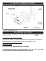
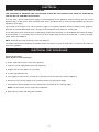
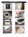
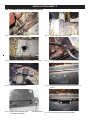
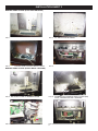
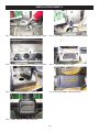
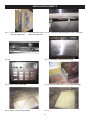
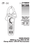
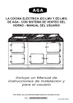
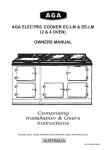
AGA 13 AMP RETRO-FIT WITH AIMS
(OIL TO ELECTRIC)
FITTING INSTRUCTIONS
LEAVE WITH CUSTOMER
For use in GB and IE
02/12 EINS 515736
OIL TO ELECTRIC CONVERSION INSTRUCTIONS
l
ISOLATE ELECTRIC SUPPLY, OIL SUPPLY AND WATER SUPPLY (BOILER MODELS),
BEFORE COMMENCING WORK.
BOILER MODELS (OCB AND OEB)
IMPORTANT NOTE: The boiler must be removed completely and the supply pipework either
removed or suitably capped. This plumbing works need to be carried out PRIOR to the oil to
electric conversion.
AGA OCB MODELS (2 OVEN MODELS WITH BOILER)
Isolate water supply, disconnect, drain and remove boiler completely from cooker. Remove or cap-off supply pipework.
NOTE: The exisiting barrel, burner chamber and burner housing can be re-used for this conversion.
AGA OEB MODELS (4 OVEN MODELS WITH BOILER)
POST-2000 OEB MODELS
Remove boiler and pipework. NOTE: A NEW BARREL WILL BE REQUIRED.
PRE-2000 OEB MODELS: (OLDER 4-OVEN MODELS WITH BOILER)
After the boiler and connecting pipework have been removed and suitably capped, these models will require, A NEW
BARREL, A NEW BURNER CHAMBER AND NEW BURNER HOUSING TO BE FITTED.
2
DE-COMMISSION OIL SUPPLY AND REMOVE OIL CONTROLS
1. Turn off oil supply, disconnect supply to appliance (preferably outdoors) and cap off. Turn on supply and test for leaks
2. Disconnect and drain oil control valve, taking care not to spill any oil. Remove oil valve and mounting bracket from side
panel.
3. Cap off oil supply pipework using fitting provided. (See Installation Sheet 1, Fig. 2).
4. Remove inner burner housing door.
5. Disconnect oil pipe to burner. Seal pipe, remove oil burner and supply pipe.
6. Remove access plate from base of burner housing and remove pipework.
7. From inside burner housing, remove fire valve probe (feed oil valve cable through guide tube, then feed fire valve probe
out through tube). (See Installation Sheet 1, Fig. 1).
8. Remove thermostat, thermostat knob and fixing bracket from burner housing.
9. Remove thermostat phial (from inside of roasting oven), remove thermostat and phial mounting bracket.
REMOVE INSULATION
1. Remove top plate, insulation and vermiculite from LEFT HAND SIDE of cooker.
2. Remove boiling plate and D-baffle from barrel.
3. Remove barrel.
MODIFICATIONS TO PRE-2000 MODELS ONLY (CAST BURNER HOUSING)
(See Installation Sheet 2, Figs. 1 - 8)
1. Remove phial guide tube from top of burner housing.
2. Open out the hole in the top of the cast burner housing (to take fitting for new flexible conduit). (See Installation Sheet,
Fig. 3).
3. Drill and tap hole in top of roasting oven (for M6). (See Installation Sheet 2, Fig. 1).
4. Open out hole in top LHS roasting oven (as shown). (See Installation Sheet 2, Fig. 2).
5. Fit flexible conduit (guide tube) between top burner housing and hole in roasting oven (fit new bracket to top roasting
oven using M6 screw). (Installation Sheet 2, Fig. 4). Make sure it does not come into contact with outer barrel.
6. Remove bolts from thermometer location casting.
7. Fix casting into place using longer 5/16” screws and washers (provided).
8. Feed new thermocouple and overheat thermostat phial through new guide tube into roasting oven.
9. Fix end of thermocouple and overheat phial to new phial mounting plate. Position thermocouple as shown. (See
Installation Sheet 2, Fig. 7).
10.Fix phial mounting plate onto extended 5/16” screws using 5/16” nuts (provided).
11.Ensure phial and thermocouple are in the groove in the top of the roasting oven, and not touching the cast iron.
3
FIT STAINLESS STEEL TUNNEL
1. Fit new stainless steel tunnel (between barrel and roasting oven).
2. Replace barrel (use new graphite barrel gasket and new rope seal). (See Installation Sheet 1, Figs. 3 & 4).
MODIFY INNER BURNER DOOR (FOR POST-2000 MODELS ONLY)
(See Installation Sheet 3, Figs. 5 - 8).
Before fitting the burner door into the sheet metal burner housing, the door has to be modified as follows:
a)
b)
c)
d)
e)
Remove lower fixing from pad on front of door (M5 screw).
Remove large pad from rear of door.
Fix the M5 x 60mm screw (provided) through rear of door, so that it projects out the front.
Re-fit large pad to rear of door.
This M5 stud is used to attach the control back cover using M5 nuts and washers provided. (See Installation
Sheet 3 Figs. 5 - 8).
FIT ELEMENT AND ELECTRICAL CONTROLS
1. Position new element platform and pads inside ashpit. (See Installation Sheet 1, Fig. 5).
NOTE:
Height of 2-oven platform is 120mm
Height of 4-oven platform is 160mm
2. Position element on top of platform (through barrel). Feed element tails through into burner housing. Route tails through
slot in front of platform as shown. (See Installation Sheet 1, Fig. 6).
3. Feed element tails through holes in new burner door, and fit new burner door (hook-on). (See Installation Sheet 3, Figs.
1 and 5).
NOTE: Post 2000 (sheet metal burner housing). Burner door requires M5 stud fitting.
4. Fit new insulation blanket into burner housing (Cast iron and sheet metal versions). (See Installation Sheet 3, Fig. 2).
5. Feed 13 amp mains cable in through existing guide tube and into aperture in base of burner housing.
6. To fit the control back cover to burner housing:Pre-2000 Cookers (Cast burner housing):- Remove the lower fixing from the pad on the burner door. Put control back
cover into position (feed element tails through aperture). Screw through the slot into the burner door (See Sheet 3, Fig.
3).
NOTE: Take care not to dislodge burner door. Then fix cover to burner housing base (2 screws).
Post-2000 Cookers (Sheet metal housing):- Put control back cover into position (feed element tails through
aperture).Fix cover onto M5 stud on burner door using M5 nuts and washers (See Sheet 3, Fig. 6). Then fix cover to
burner housing base (2 screws).
7. Fix overheat thermostat to LH side of control back cover and feed thermostat phial through guide tube into roasting
oven. (See Installation Sheet 5, Figs. 1 and 2). Plug end of guide tube with Rockwool.
8. Fit new AIMS control panel to control back cover.
9. Feed thermocouple through guide tube into oven. Attach thermocouple tip and overheat thermostat phial to mounting
bracket, attach bracket to oven. (Post 2000 sheet metal burner housing). Ensure thermocouple goes through notch in
control panel as shown. (See Installation Sheet 4, Fig. 3) Thermocouple and sensor must not touch the cast iron.
10.Attach element tails to terminal block. Ensure tails are routed away from PCB.
4
11. Fix mains cable through cable clamp. Fix cable clamp to control panel (See Installation Sheet 4, Figs. 1 and 2).
12. Attach mains wiring to control panel.
13. Outside the appliance route mains cable through ‘P’ clips provided, and attach to hank bushes on side panel (See
Installation Sheet 5, Fig. 5).
14. See ‘Electrical’ and ‘Electrical Test Procedure’ sections.
PAD BELOW SIMMERING PLATE
(See Installation Sheet 1, Fig. 8)
1. Remove simmering plate.
2. Fit new insulation pad on RH side of weir (ridge below simmering plate), as shown.
This must block off the flue passage. Take care, do not block off the vent hole in the top of the roasting oven.
FLUE SHROUD AND BLANKING PLATE
(See Installation Sheet 4, Figs. 4 - 7)
1. Remove flue shroud and remove flue baffle plate.
2. Fit new flue box blanking plate assembly, as follows:a)
b)
c)
d)
e)
f)
g)
Remove front (RH) fixing from flue box.
Feed blanking plate assembly into place with raised part at rear.
Replace front fixing using a large washer and longer bolt (provided) to hold plate down.
Put thin layer fire clay around edges of blanking plate.
Attach mesh to rear flue shroud using silicone. (Align slot in mesh with second slot from top of flue shroud).
Position flue shroud over flue box so that lever arm projects through second slot from top.
Lever should move freely from left to right. Put lever in left hand position (vent closed).
MODIFY HOTCUPBOARD (4-OVEN MODELS ONLY)
1. Remove warming plate from top of hot cupboard (4-oven cookers only).
2. Fit blanking plate to LH side. Drill 2 holes for self-tap screws. (See Installation Sheet 5, Fig. 6).
3. Place 2 pads on top of hot cupboard. (See Installation Sheet 5, Fig. 7).
4. Replace warming plate, using new sealing strips.
HEAT INDICATOR PLATE, INSTRUCTION PLATE AND DATA PLATE
1. If the heat indicator plate is numbered either 4, 5 or 6, then swap the plate for one which is two numbers lower (either
1, 2 or 3).
2. Remove instruction plate from outer burner door (if fitted) and reverse the plate (See Installation Sheet 5, Fig. 3).
3. Write original cooker serial number onto data label.
4. Attach data plate label top LH side of control back cover (See Installation Sheet 5, Fig. 4).
5. Record the serial number of the cooker and refer this serial number to Service Centre.
CHECK LEVELS AND RE-BUILD
1. Replace simmering plate and boiling plate, check level and adjust as necessary.
2. Refill with vermiculite and fit new top plate blanket, and re-fit top plate.
5
ELECTRICAL
WARNING: THIS APPLIANCE MUST BE EARTHED.
THIS APPLIANCE IS DESIGNED FOR THE VOLTAGE STATED ON THE RATING PLATE, WHICH IS SITUATED ON
THE TOP OF THE CONTROL BACK COVER.
A 13 amp 230v ~ 50 Hz fused electrical supply is required adjacent to the appliance. External wiring to the unit must be
installed using a 3 core silicon - SIHF insulation cable, and in accordance with the current wiring regulations and any local
regulations which apply.
The method of connection to the mains electricity supply must facilitate complete electrical isolation of the appliance,
preferably by a fused double pole switch, having a contact separation of at least 3mm in both poles.
A 13A safety plug can be used, however, we do strongly recommend connection via a fused double pole switch for integrity
of the connection. If a 13A safety plug is used it must be of a high quality and must be to BS1363 - 3: 1995 (13A Plugs,
socket, outlets and adaptors).
NOTE: Switched spur outlet should only serve the appliance.
The isolator should not be positioned immediately above the cooker, but must be fitted within 1.5 metres of the cable exit
point of the appliance.
ELECTRICAL TEST PROCEDURE
Final Electrical Test using (CLARE) and Flash Test
Flash Test Procedure
(Earth Appliance Test Simulation)
1. Select 1250v Flash Test on Clare Test equipment.
2. Plug the 13 amp supply plug into the test equipment.
3. Depress the red ‘Test Button’ for 3 seconds.
4. A ‘Pass’ light will illuminate.
5. If the appliance fails the test, re-check all circuits and correct the fault and re-test the appliance.
6. Disconnect from the test equipment and connect cooker to its permanent supply.
7. A full load test will be performed using a clamp meter connected to the incoming supply.
NOTE: The test results 10.5/11 amps normal operation.
8. Make notes of results and disconnect all leads.
6
INSTALLATION SHEET 1
FIG. 1 OIL CONTROLS TO BE REMOVED
FIG. 2 CAP OFF OIL SUPPLY
FIG. 3 FIT NEW ROPE SEAL
FIG. 4 FIT TUNNEL BETWEEN BARREL & OVEN
FIG. 5 PLATFORM AND PADS INTO ASHPIT
FIG. 6 POSITION TAILS THROUGH SLOT IN PLATFORM
FIG. 7 POSITION ELEMENT
FIG. 8 FIT PAD BELOW SIMMER PLATE
7
INSTALLATION SHEET 2
PRE- 2000 MODELS ONLY (CAST BURNER HOUSING)
FIG. 1 DRILL AND TAP HOLE (M6)
FIG. 2 OPEN OUT HOLE INTO OVEN
FIG. 3 MODIFY HOLE FOR FLEX CONDUIT FITTING
FIG. 4 FIT LOCATION BRACKET TO TOP OVEN
FIG. 5 USE LONGER FIXINGS
FIG. 6 STUDS PROTRUDING THROUGH ROOF OF
OVEN
FIG. 7 POSITION ELEMENT AND
OVERHEAT SENSOR
10mm SPACING
FIG. 8 ATTACH PHIAL PLATE (AS SHOWN)
8
INSTALLATION SHEET 3
BURNER DOOR FITTING (CAST IRON HOUSING)
FIG. 1
FIG. 3
FIG. 2 FIT INSULATION BLANKET
FIXINGS FOR CONTROL BACK COVER
FIG. 4
BURNER DOOR FITTING (SHEET METAL HOUSING)
FIG. 5 M5 STUD FITTED TO BURNER DOOR
FIG. 6 FIXINGS FOR CONTROL BACK COVER (M5)
NUTS, WASHERS PLUS 2 SCREWS
FIG. 7
FIG. 8
9
INSTALLATION SHEET 4
FIG. 1 REMOVE CABLE CLAMP. ATTACH MAINS CABLE
FIG. 2 FIX CABLE CLAMP TO CONTROLS PANEL
FIG. 3 ROUTE THERMOCOUPLE THROUGH NOTCH
FIG. 4 REMOVE FRONT FIXING
FIG. 5 POSITION AND FIRE CLAY IN PLACE
FIG. 6 SILICONE MESH ONTO SHROUD
FIG. 7 LEAVE ARM IN CLOSED POSITION
10
INSTALLATION SHEET 5
FIG. 1 POST 2000 STAT PHIAL
SUPPORT BRACKET
PRE 2000 STAT PHIAL FIG. 2A POSITION THEROCOUPLE (10mm SPACING)
SUPPORT BRACKET
FIG. 2B
FIG. 3 REVERSE INSTRUCTION PLATE
FIG. 4 DATA PLATE POSITION
FIG. 5 ROUTE CABLE USE ‘P’ CLIP AND GROMMET
FIG. 6 DRILL 2 HOLES (AS SHOWN)
FIG. 7
11
For further advice or information please contact
your local distributor/stockist
With AGA-Rangemaster’s policy of continuous
product improvement, the Company reserves the
right to change specifications and make
modifications to the appliance described at any
time.
Manufactured by
AGA-Rangemaster
Station Road
Ketley Telford
Shropshire TF1 5AQ
England
www.agaliving.com
www.agacookshop.co.uk
12