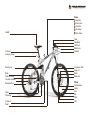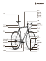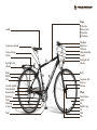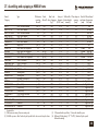
1
Please read pages 6 and 7 before your first ride! Please perform the functional check on pages 8 and 9 before every ride! U SER MANUAL Please go through the check list of the delivery receipt together with your MERIDA dealer Frame: 1 Top tube 2 Down tube 3 Seat tube 4 Chainstay 5 Rear frame Saddle Stem Handlebar Shift lever Brake lever Headset Seat post Seat post clamp 1 3 Rear shock Brake Front derailleur Cassette sprockets Rear derailleur Chain Chainring Crank set Pedal 2 5 4 Suspension fork Drop-out Brake Brake disc Wheel: Quick-release Spoke Tires Rim Valve Hub Frame: 1 Top tube 2 Down tube 3 Seat tube 4 Chainstay Saddle Stem Seat post Seat post clamp Handlebar Brake/shift lever 1 Headset Brake Brake 3 2 Fork Drop-out Cassette sprockets Front derailleur Rear derailleur Chain Chainring Crank set 4 Wheel: Quick-release Tire Spoke Rim Valve Hub Frame: 1 Top tube 2 Down tube 3 Seat tube 4 Chainstay Saddle Handlebar Brake lever Shift lever Stem (adjustable) Headset Front light with reflector Suspension seat post Seat post clamp Carrier 1 Rear light with reflector Brake Reflector Lock Cassette sprockets Front derailleur Rear derailleur Kick stand Chain Chainring Crank set Pedal 3 2 Brake Suspension fork Drop-out Dynamo 4 Wheel: Quick-release Spoke Rim Reflector ring Tire Valve Hub 1. Introduction Dear customer, In purchasing this MERIDA bike you have chosen a product of high quality and technology. Your new bike was produced with care and expertise and has been equipped with the best possible components. Your MERIDA dealer has assembled the bike, checked the function and made adjustments according to your needs so that you can enjoy cycling with complete peace of mind from the very first metres. In this brochure we have compiled for you a wealth of tips on how to use and adjust your bike as well as an extensive account of things worth knowing about bike maintenance and care. Please read these pages carefully – you will find it worthwhile, even if you have been cycling a whole lifetime. Bike technology has developed at a rapid pace during recent years. So before setting off on your new bike, please be sure to read chapter 3. “Before your FIRST ride”. To make sure cycling gives you the greatest possible enjoyment, you should always carry out the minimum functional check described in chapter 4. “Before EVERY ride” before mounting your bike. This manual cannot teach you the skills of a bike mechanic. Even a manual as big as an encyclopaedia, could not cover all possible combinations of bikes and parts. Therefore, this manual focuses on the bike as well as on some common parts and important notes and warnings. It does not, however, teach you the skills of a bike mechanic. When doing maintenance or repair work, be aware that the extensive instructions provided in your manual only refer to MERIDA bikes and not necessarily to other bikes. Due to frequent redesigns and modifications, it may be that some of the jobs are not described fully or in every detail. For this reason be sure also to observe the instructions of our component suppliers which you have received from your MERIDA dealer. 1. Introduction Note that the instructions may require further explanations, depending on the experience and/or skill of the person doing the work, some jobs may require additional (special) tools or supplementary instructions. In your own interest, never do any work unless you feel absolutely sure about it. If in doubt, ask your MERIDA dealer for advice! Before you set off, let us point out a few things to you that are very important to us being cyclists ourselves. Never ride without a properly adjusted helmet and take care always to wear suitable clothing. As a minimum, you should wear straight cut trousers and shoes which are compatible with the pedal-system. Always ride carefully on public roads and observe the traffic rules so as not to endanger yourself or others. This manual cannot teach you how to ride. Even a manual as big as an encyclopaedia, could not cover all possible conditions, different types of bikes and riders. Therefore, this manual focuses on the bike and important notes and warnings, not teaching you how to ride and not teaching you the rules of traffic. Please be aware that cycling is a hazardous activity that requires the rider to stay in control of his or her bike at all times. Like any sport, bicycling involves risk of injury and damage. By choosing to ride a bike, you assume the responsibility for the risk. Always keep in mind that there are no safety devices protecting you from injury, such as e.g. the bodywork or the airbag of a car. Therefore, always ride carefully and respect the other traffic participants. Never ride under the influence of drugs, medicals, alcohol or when you are tired. Do not ride with a second person on your bike and never ride without having your hands on the handlebar. Observe the legal regulations concerning offroad cycling. These regulations may differ in each country. Please respect nature when riding off-road. For your own safety stay on marked and well-maintained trails and forest roads. 1. Introduction First we would like to make you familiar with the various components of your bike. For this purpose, please unfold the front and rear cover of this booklet. Here, you will find pictures of all types of bikes showing all the essential components. Leave this page unfolded while you read so that you can quickly locate the components referred to in the text. The illustrations show arbitrary MERIDA bikes – not every bike will look like this. Nowadays, there are numerous types of bikes designed for specific purposes and equipped accordingly. The range of MERIDA bikes includes: City bikes/All Terrain Bikes (ATB) Cross bikes Fitness bikes Mountain bikes (MTBs)/Hardtail/ Full Suspension Road bikes Trekking bikes BMX bikes Kids’ bikes If your bike is made of carbon, you will find important notes as of chapter 28. “Special characteristics of carbon”. Some notes on this manual The table of contents will help you to quickly find whatever information you are looking for. Pay particular attention to the following symbols! This symbol means that your life or health may be in danger unless you comply with the instructions given or carry out the measures prescribed. If your bike is equipped with rear shock, please note chapter 15. “The rear shock”. This symbol warns you about actions that could lead to damage of property or environment. This symbol signifies information about how to handle the product or refers to a passage in the user manual that deserves your special attention. The possible consequences described above are not repeated every time one of the symbols appears! 2. Table of contents 1. Introduction.................................................1 2. Table of contents.........................................4 3. Before your first ride...................................6 4. Before every ride........................................8 5. After an accident.......................................10 6. Legal requirements for riding on public.......... roads........................................................12 7. How to use the quick-releases....................13 7.1 Use of quick-releases................................13 7.2 Notes on the mounting of thru axle wheels15 8. Adjusting the bike to the rider ..................17 8.1 Adjusting the saddle to the correct height...17 8.2 Adjusting the height of the handlebars.......20 8.2.1 Conventional stems.............................20 8.2.2 Adjustable stems................................21 8.2.3 Stems for threadless systems, ................. the so-called Aheadset system.............22 8.3 Correcting the fore-to-aft position and .......... horizontal tilt of the saddle........................24 8.3.1 Adjusting saddle position and tilt.........24 8.4 Adjusting the gripping distance . .................. of the brake levers....................................25 8.5 Adjusting the tilt of the handlebars, brake levers and bar ends .......................25 8.6 Adjusting the handlebar position . ................ by turning the handlebar...........................26 8.7 Adjusting the bar ends.............................27 8.8 Adjusting the tilt of the handlebars and brake levers with road, triathlon and cyclocross bikes........................................28 8.9 Adjusting the tilt of the handlebars and brake levers with road, triathlon and cyclocross bikes........................................29 8.10Seating position on BMX and dirt bikes.....30 9. The brake system......................................31 9.1 Brakes – how they work and what to do about wear..............................................31 9.2 Rim brakes (general) ...............................32 9.3 Checking, adjusting and synchronizing V-brakes..................................................32 9.3.1 Functional check.................................33 9.3.2 Synchronizing and adjusting the brakes..........................................33 9.4 Checking, adjusting and synchronizing racing or side-pull brakes ........................34 9.4.1 Functional check.................................34 9.4.2 Vertical adjustment of the brake pads........................................34 9.4.3 Synchronizing and adjusting the side-pull brakes ...........................34 9.5 Characteristics of cantilever brakes . .........35 9.5.1 Functional check.................................35 9.5.2 Synchronizing and adjusting the cantilever brakes...........................35 9.6 Rim brakes (U-brakes)..............................36 9.6.1 Checking, adjusting and synchronizing U-brakes......................36 9.6.2 Adjustment possibilities at the lever......37 9.6.3 Adjustment possibilities at the brake pads and bowden cables....................37 9.6.4 Adjustment of the rear brake at the rotor system..............................38 9.6.5 Synchronization.................................38 9.7 Drum or roller brakes...............................39 9.7.1 Checking and readjusting...................39 9.8 Back-pedalling brakes (coaster brakes)......40 9.9 Disc brakes..............................................41 9.9.1 Checking and adjusting hydraulic disc brakes........................................42 9.9.2 Checking, adjusting and synchronizing mechanical disc brakes.......................43 10. The gears.................................................44 10.1Derailleur gears.......................................44 10.1.1 How they work and how to use them......................................45 10.1.2 Mountain bike gear levers.................45 10.1.3 Road bike gear levers.......................48 10.1.4 Bar end gear levers..........................49 10.1.5 Inspecting and adjusting the derailleur gear............................50 10.1.6 Rear gear changer (rear derailleur)...50 10.1.7 Front gear changer (front derailleur)..52 10.2 Multi-speed hubs - internal gear hubs......53 10.2.1 How they work and how to use them53 10.2.2 Readjustment....................................54 10.2.3 Readjustment of the chain tension of bikes with adjustable drop outs ........54 10.3 Chain maintenance................................55 10.3.1 Chain wear......................................56 11. The wheels...............................................57 11.1 Tires, tubes, rim tapes, valves, tire pressure .........................................57 11.2 Rim trueness, spoke tension.....................60 11.3 Wheel fastening with wheel nuts or quick-releases....................................61 11.4 Repairing punctures...............................62 11.4.1 Dismounting wheels..........................62 11.4.2 Dismounting tires..............................63 11.4.3 Mounting tires..................................64 11.4.4 Mounting wheels..............................66 12. The headset.............................................67 2. Table of contents 12.1 Checking the bearing play of the headset............................................67 12.2 Adjusting the conventional headset..........67 12.3 Adjusting the threadless headset (Aheadset).............................................68 13. The suspension fork.................................70 13.1 Adjusting suspension forks......................70 13.2 Suspension fork maintenance..................72 14. The suspension seat post..........................73 14.1 Adjustment............................................73 14.2 Check and maintenance.........................74 15. The rear shock.........................................75 15.01 Notes on the sitting position..............75 15.02 Application and intended use............76 15.1 General notes on the adjustment of the frame...........................................78 15.2 Adjusting the rear shock absorber..........79 15.2.1 Adjusting the shock absorbers...........79 15.2.2 Adjusting the damping......................82 15.2.3 Making corrections on a test ride.......82 15.3 Checks, care and maintenance of the rear shock...................................83 15.3.1 Care................................................83 15.3.2 Check..............................................83 15.3.3 Maintenance....................................84 15.3.4 Service intervals...............................85 16. The pedals...............................................86 16.1 Different systems – how they work at a glance............................................86 16.2 Adjustment and maintenance..................87 17. The lighting set.........................................88 17.1 How it works.........................................88 17.2 Troubleshooting......................................89 17.3 Adjusting the front light..........................89 18. Dirt bikes – special features......................90 19. Kids’ bikes...............................................91 19.1 What parents must bear in mind.............91 19.2 Notes on BMX bikes...............................92 19.3 Adjustment of kids’ bikes........................93 19.4 Training wheels......................................94 20. Helmets, accessories.................................95 20.1 Helmets.................................................95 20.2 Accessories............................................95 21. Baggage..................................................96 22. Taking children with you..........................97 22.1 Child carriers.........................................97 22.2 Child trailers..........................................98 23. Transport by car.......................................99 24. Cleaning and caring...............................100 25. Storing the bike.....................................101 26. Service and maintenance schedule.........102 27. Assembling and equipping a MERIDA frame.......................................104 28. Special characteristics of carbon.............106 28.1 Carbon - special characteristics.............106 28.1.1 General notes on care....................107 28.1.2 Protection of the frame finish...........107 28.1.3 What to bear in mind when braking with carbon wheels............108 28.2 MERIDA framesets................................109 28.2.1 Determining the correct frame size...109 28.2.2 Before your first ride.......................109 28.2.3 Assembling and equipping a MERIDA-frame...............................110 28.2.4 The headset....................................112 28.2.5 Bottom bracket bearings.................112 28.2.6 Chainsuck protection......................112 28.2.7 Rear drop-out spacing....................113 28.2.8 Replaceable derailleur hanger.........113 28.2.9 Front derailleur hanger...................113 28.2.10Permitted torques for seat post binder with Allen bolt.....................114 28.2.11Bottle cage.....................................114 28.3 Carbon forks.......................................116 28.3.1 Before your first ride.......................116 28.3.2 Adjusting the headset.....................116 28.3.3 Mounting the full carbon fork with carbon steerer.........................117 28.4 Carbon handlebars and stems..............120 28.4.1 Before your first ride.......................120 28.4.2 Mounting.......................................120 28.5 Carbon seat post..................................124 28.5.1 Before your first ride.......................124 28.5.2 Adjusting the correct saddle height..124 28.5.3 Adjusting the position and angle of the saddle.........................125 28.5.4 Mounting the carbon seat post........126 28.5.5 Mounting the saddle.......................126 29. Recommended torques for bolted connections............................................127 29.1 Recommended torque settings: Campagnolo/Shimano/Avid/ SRAM components...............................128 29.2 Recommended torque settings: FSA components..................................129 29.3 Recommended torque settings for other components............................130 30. Warranty and guarantee........................131 30.1 Introduction.........................................131 30.2 A note on wear....................................132 30.3 Guarantee on MERIDA bikes................133 Imprint..........................................................134 3. Before your first ride 1. Road and fitness bikes are exclusively designed for use on roads with a smooth, hard surface. City, cross and trekking bikes are intended for hard-surface roads and paths. Mountain bikes are suitable for off-road use, but not for drops, dual slalom, free ride and downhill. For these purposes, we have special dirt, free ride and downhill models. Depending the model, dirt bikes are also suitable for drops, dual slalom, free ride and downhill. BMX bikes are intended for use on secured terrain. There are different types of bikes which are either suitable for tricks and show rides on smooth ground or for jumps and freestyle on special obstacle courses or for races. For your own safety, do not over estimate your riding skills. Please note that, though looking easy, the tricks of a professional are hazardous to your life and limb. Always protect yourself with suitable clothing. Only use your bike according to its intended purpose as it may otherwise not stand up to the stress and fail! If used other than for its intended purpose, the warranty will become void. For cycling on public roads, please observe the regulations of the respective countries. 2. Each of our bikes are designed for a maximum overall weight (rider, baggage and bike together). In chapter 27. “Assembling and equipping a MERIDA frame“ you will find a table listing the additional load permitted for the different bike models. Here a short overview: Road, fitness and mountain bikes 120 kg Cross and trekking bikes: Men’s version 120 kg Ladies’ version 100 kg City bikes: 100 kg The permissible baggage weight is marked on the carrier. Before you tow a trailer or before you mount a child carrier, please have a look at chapter 27. “Assembling and equipping a MERIDA frame“ and chapter 22. “Taking children with you”. 3. Before your first ride 3. Are you familiar with the brake system? Check whether the lever of the front brake is in the position you are used to (right or left). If this is not the case, you will need to train to get used to it, as inadvertent use of the front brake can make you crash! Or ask your MERIDA dealer to switch the brake levers. Your new bike is equipped with modern brakes which may be far more powerful than those you are used to! Be sure to first practise using the brakes off public roads! You will find more information about brakes in chapter 9. “The brake system“ and in the brake manufacturers’ manuals your bike is supplied with. Please note that your bike’s braking power and road grip will both be severely reduced in wet conditions. Look well ahead when riding on wet roads and go well below the speed you would ride at in dry conditions. 4. Are you familiar with the type and functioning of the gears? If not, make yourself familiar with the gears in a place free of traffic. For more information see chapter 10. “The gears“. 5. Are saddle and handlebars properly adjusted? The saddle should be set to a height from which you can just reach the pedal in its lowest position with your heel. Check whether your toes reach to the floor when you are sitting on the saddle. Your MERIDA dealer will be pleased to help you, if you are not happy with your sitting position. You will find more information on this in chapter 8. “Adjusting the bike to the rider“. 6. If your bike is equipped with clipless or step-in pedals: Have you ever ridden in the shoes they go with? First practise locking one shoe onto a pedal and disengaging it while standing on the other leg! For more information see chapter 16. “The pedals“. You will find more information on the pedals in the enclosed pedal manual. 7. If you bought a suspension bike, you should ask your MERIDA dealer to adjust the suspension mechanism to your needs. Improperly adjusted spring components are liable to malfunction or become damaged. In any case, they will impair the performance of your bike as well as your safety whilst riding. You will find more information about this in chapter 13. “The suspension fork“, chapter 14. “The suspension seat post“, chapter 15. “The rear shock“ and in the enclosed manuals. 4. Before every ride Check the following points before setting off: 1. Are the quick-release levers or nuts of the front and rear wheel, the saddle and other components properly closed? For more information see chapter 7. “How to use the quick-releases“. 2. Are the tires in good condition and do they have sufficient pressure (thumb test, how far can you press the tire to the rim with your thumb)? For more information see chapter 11. “The wheels“. Improperly closed quick-releases can cause components to come loose. This can cause a serious accident! 3. Spin the wheels to check whether the rims are true. Watch the gap between rim and brake pad or, in case of disc brakes, between frame and rim. Untrue rims can be an indication of tires with ruptured sides or broken axles or spokes. For more information see chapter 11. “The wheels“. 4. Test the brakes while standing by firmly pulling the brake levers towards the handlebars. The brake pads of calliper brakes must hit the rim with their entire surface without touching the tire. You should not be able to pull the lever all the way to the handlebars! Check the lines for leaks! With disc brakes, you should have a stable pressure point at once. If a stable pressure point is only achieved after having repeatedly pulled the brake lever, you should have the bike checked by your MERIDA dealer. For more information see chapter 9. “The brake system“. 4. Before every ride 5. If you want to ride on public roads, you must equip your MERIDA bike according to the regulations of your country. Riding without a light and without reflectors in the dark or when visibility is poor, is very dangerous because you will not be seen by other road users. Turn on the lights as soon as dusk sets in. For more information see chapter 6. “Legal requirements for riding on public roads“. 6. Let your bike bounce on the ground from a small height. If there is any rattling, find out where it comes from. Check the bearings and bolted connections, if necessary. 7. If your bike is suspended, check the frame: Lean on your bike and see whether the spring elements retract and extend as usual. 9. Do not forget to take a high quality lock with you on your ride. The only way to effectively protect your bike against theft is to lock it to an immovable object. 8. If your bike has a kick-stand, check that it is fully raised before you set off. ! Do not use your bike, if it fails on one of these points! If in doubt, contact your MERIDA dealer! A defective bike can lead to serious accidents! 5. After an accident 1. Check whether the wheels are still firmly fixed in the drop-outs and whether the rims are still centered with respect to the frame or fork. Spin the wheels and watch the gap between rims and brake pads. If the width of the gap changes markedly and you have no way to true the wheel on site, you will need to open the brakes a little so that the rim can run between the brake pads without touching them. In this case remember that the brakes will not act as powerfully as you are used to. 2. Check that the handlebars and stem are neither bent nor ruptured and whether they are level and upright. Check also whether the stem is firmly fixed in the fork by trying to twist the handlebars relative to the front wheel. Also, briefly lean on the brake levers to make sure the handlebars are firmly fixed in the stem. For more information see chapter 8. “Adapting the bike to the rider“ and chapter 12. “The headset“. For more information see chapter 9. “The brake system“ and chapter 11. “The wheels”. through all the gears. Pay particular attention when switching to the small gears, making sure the gear changer does not get too close to the spokes as the chain climbs onto the larger sprockets. If the derailleur or the drop-outs have been bent, this can cause the gear changer to collide with the spokes. This in turn can destroy the gear changer, the rear wheel or the frame! Check the derailleur function, as a displaced gear changer can throw off the chain, thus interrupting the power train. For more information see chapter 10. “The gears“. 3. Check whether the chain still runs on the chainwheel and sprockets. If your bike fell over to the chain side, check that the gears still work properly. Ask a helper to lift the bike by the saddle, then gently switch 10 5. After an accident 4. Make sure the saddle is not twisted using the top tube or the bottom bracket shell as a reference. Bent parts, especially parts made of aluminium, can break without any previous warning. They must not be repaired, i.e. straightened, as this will not reduce the imminent risk of breakage. This applies in particular to forks, handlebars, stems, crank sets and pedals. When in doubt, replace these parts for your own safety. 7. If your bike is equipped with parts made of carbon, please bear in mind the particularities of this material as described in chapter 28. “Special characteristics of carbon”. 5. Lift your bike up a few centimetres and let it bounce onto the ground. If this causes any sort of noise, search for loose bolt connections. 6. Finally, take a good look at the whole bike to detect any deformation, discolouration or cracks. If your bike has passed the complete test successfully, ride back home very carefully by taking the shortest possible way. Do not accelerate or brake hard and do not ride your bike out of the saddle. If you are in doubt about the performance of your bike, have yourself picked up by car instead of taking any risk. Back home, the bike must be checked thoroughly again and damaged parts must be repaired. In case of doubt, see your MERIDA dealer. 11 6. Legal requirements for riding on public roads If you want to use your bike on public roads, it has to be equipped according to the regulations of your country. This applies in particular to the reflectors and the lighting set! Ask your MERIDA dealer or the distributor in your country. You will find the address on the cover of this manual or on www.meridabikes.com. 12 7. How to use the quick-releases 7.1 Use of quick-releases How to fasten components securely Although handling quick-releases is very easy, they have repeatedly been the cause of accidents resulting from improper use. Quickrelease retention mechanisms essentially consist of two manipulable parts: Open the quick-release. The word “Open“ should now be readable on the lever. Over the second half of its travel, the force you need to move it, should increase considerably. Towards the end of its travel, the lever should be very hard to move. Use the ball of your thumb while your fingers pull on an immovable part such as the fork or a rear stay, but not on a brake disc or spoke, to push it in all the way. 1. The hand lever on one side of the hub which creates a clamping force via a cam when you close it. 2. The tightening nut on the other side of the hub with which to set the preliminary tension on the threaded rod. Make sure the levers of both quick releases are always on the side opposite the chain. This will help you to avoid mounting the front wheel the wrong way round. Move the lever back as if to close it. Now you should be able to read the word “Close” on the outside of the lever. From the start of the closing movement up to about the first half of its travel, the lever should move very easily, i.e. without clamping the wheel. In its end position the lever should be parallel to the bike, i.e. it should not stick out to the side. The lever should lie close to the frame, i.e. the fork, so that it cannot be opened accidentally. To check whether the lever is securely locked, try to turn it while it is closed. Apply pressure to the end of the hand lever as if to turn it in a circle. 13 7. How to use the quick-releases Improperly closed quick-releases can cause parts to come loose. This can result in an accident with severe injuries. If you close a quick-release, do not pull the lever with your fingers propped up against a brake disc or a spoke. Close the lever again and check the position for tightness. If the lever can no longer be turned, it is properly fastened. Finally, lift the bike up a few centimetres, so that the wheel no longer touches the ground, and hit the tire from above. If the quick-release is properly fastened, the wheel will remain firmly fixed in the drop-outs of the frame. If your seat post is equipped with a quickrelease retention mechanism, check whether the saddle is firmly fixed by trying to twist it relative to the frame. 14 7. How to use the quick-releases 7.2 Notes on the mounting of thru axle wheels With a conventional thru axle system, slide the thru axle through fork and hub so that the head of the Allen bolt comes to a rest on the right side, seen in direction of motion. Once the axle is mounted, let the fork deflect a few times, thus excluding that the axle gets jammed. Screw the nut onto the axle and tighten it according to the enclosed instructions of the fork manufacturer. Finally tighten the four Allen bolts at the front side of the fork, according to the enclosed instructions of the fork manufacturer in order to lock the axle. Check the bolts after one to two operating hours and then every 20 hours. If your bike is equipped with a thru axle system with quick-releases, put the wheel into the fork and mount the brake disc in the brake calliper. Bring the wheel into the right position between the drop-outs and slide the axle with open quick-release levers from the right side through the drop-out and the hub. As soon as the axle thread engages with the thread of the left drop-out, close it by turning it clockwise. Close the thru axle quick-release lever like a usual quick-release lever. From the start of the closing movement up to about the first half of its travel, the lever should move very easily without clamping the wheel, whereas over the second half of its travel the force you need to move it should increase considerably. Towards the end of its travel, the lever should be very hard to move. Use the palm of your hand while your fingers pull on an immovable part, such as the fork leg, but not on a spoke or the brake disc. In its end position, the quick-release lever should be tight so that it can no longer be turned. Do not use any other tools to fix the axle. A too tight fixing of the axle can damage the axle or the fork leg. In any case make yourself familiar with the user manual of the respective fork manufacturer. 15 7. How to use the quick-releases There are other thru axle systems which are a combination of threaded axle and quickrelease system. With these systems, the wheel including brake disc, must be mounted in fork and brake calliper. Then, the thru axle must be slided through the drop-out of one fork leg into the thread of the second fork leg where it is screwed in. The fold-out screw-in fitting helps you in doing so. After this, close both quick-release levers to clamp the axle. Proceed as with regular quick-releases. From the start of the closing movement up to about the first half of its travel, the lever should move very easily without clamping the wheel, whereas over the second half of its travel the force you need to move it should increase considerably. Towards the end of its travel the lever should be very hard to move. Use a matching Allen key to adjust the initial tension of the quick-release lever. Use the palm of your hand while your fingers pull on an immovable part, such as the fork leg. Do not use any other tools to fix the axle. A too tight fixing of the axle can damage the axle or the fork leg. In any case make yourself familiar with the user manual of the according fork manufacturer. 16 8. Adjusting the bike to the rider Adjusting the bike Your body height is the decisive criterion for the frame size you need. Pay particular attention that there is enough space between your crotch and the top tube so that you won’t hurt yourself when having to get off your bike quickly. By choosing a specific type of bike, you already roughly determine the posture you will be riding in. However, some components of your bike are especially designed so that you can adjust them to your proportions up to a certain degree. These include the seat post, the stem and the brake levers. After carrying out assembly work, always make a short functional check as described in “Before every ride” and do a test ride in an unfrequented place. This will allow you to safely check whether everything is in good order. 8.1 Adjusting the saddle to the correct height The correct saddle height is the height which provides maximum pedalling comfort and efficiency. When pedalling, the balls of your big toes should be positioned above the centre of the pedal spindles. With your feet in this position, you should not be able to stretch your legs completely at the lowest point, otherwise your pedalling will become awkward. You can check the height of your saddle in the following, simple way. This is best done wearing flat-soled shoes. Sit on the saddle and put one of your heels on the pedal at its lowest point. In this position, your leg should be fully stretched and your hips should not be tilted to either side. All the tasks described in the following require experience, appropriate tools and manual skill. Take particular care when tightening bolted joints. Increase the torque bit by bit, checking the seat of the component in between. Use a torque wrench and never exceed the maximum permissible torque! To adjust the saddle height, loosen the binder bolt or quick-release lever (first read chapter 7. “How to use the quick-releases“). Use a suitable tool to release the seat post binder bolt, turning it counterclockwise by two to three turns. Now you can shift the saddle to the desired height. If you are unsure about how to do something, it will be better just to check your seating position. Consult your MERIDA dealer, if you feel you want something changed. He will see to your wishes the next time you leave your bike at the workshop, e.g. for the first inspection. 17 8. Adjusting the bike to the rider Be sure not to pull out the seat post too far. The mark on the seat post must always remain within the seat tube. As a minimum, the seat post should be inserted by 2.5 times the diameter, i.e. with a 30 mm diameter seat post, at least 75 mm of it must remain within the seat tube. Make sure the part of the seat post inserted inside the seat tube is always well greased. In case of frames with long seat tube stretching beyond the top tube, the seat post must at least reach below the height of the top tube i.e. the tip of the rear stays! This can entail a minimum insertion length of 10 centimetres or more. Do not grease seat post or seat tube, if the frame or the seat post are made of carbon. For more information see chapter 28.4 “Carbon handlebars and stems” and chapter 28.5 “Carbon seat post”. If the seat post does not move easily inside the seat tube, ask your MERIDA dealer for advice. Do not ever use brute force. Align the saddle with the frame using the saddle nose and the bottom bracket or top tube as a reference point. Clamp the seat post tight again by turning the seat post binder bolt clockwise. You should not need much strength in your hands to clamp the seat post sufficiently tight. If you do, it means the seat post is the wrong size for the frame. If you have a road bike with a very small frame, there may be a danger of your foot colliding with the front wheel. Check the position of your cleats (the plates on the soles of cycling shoes), if this applies to your bike. Never ride your bike with the seat post drawn out beyond the limit, maximum, or stop line! The seat post might break or cause severe damage to the frame. 18 8. Adjusting the bike to the rider Verify that the seat clamp is sufficiently tight by taking hold of the saddle at both ends and trying to rotate the seat post inside the seat tube. If you can rotate it, you must increase the clamping force and repeat the test. If sitting causes you trouble e.g. because it numbs your crotch, this may be due to the saddle. Your MERIDA dealer has a very wide range of saddles available and will be pleased to advise you. Check whether you can still reach the ground safely with your feet while sitting on the saddle. If not, you should lower the saddle a little, at least to begin with. Does the leg stretch test now produce the right result? Check by moving your foot and pedal to the lowest point. If the ball of your foot is exactly above the pedal centre (ideal pedalling position) your knee must be slightly bent. If this is the case, you have adjusted the saddle height correctly. With some mountain bikes, such as e.g. the dirt jump bikes, it is sensible to lower the saddle a little for some riding manoeuvres. A lower saddle is advisable in particular for riding steep descents with the mountain bike. Longer rides with a too low saddle may, however, lead to knee joint pain. The position of the saddle is very individual. Contact your MERIDA dealer and let him help you find the best position for you. 19 8. Adjusting the bike to the rider 8.2 Adjusting the height of the handlebar The height of the handlebar determines the inclination of the upper body. Lowering the handlebars gives the rider a streamlined position and brings more weight to bear on the front wheel. However, it also entails an extremely forward leaning posture which is tiring and less comfortable because it increases the strain on your wrists, arms, upper body and neck. 8.2.1 Conventional stems Release the expander bolt by two to three complete turns. You should now be able to turn the stem freely inside the fork. If this is not the case, release the bolt by tapping it softly with a hammer. With most Allen bolts, you will first need to stick the Allen key into it, because they will probably be countersunk and therefore impossible to be hit directly. Then gently tap the key with the hammer. Now you can move the handlebars and stem up and down as a whole. Do not pull the stem out beyond the mark on the shaft! According to the CEN-standard, the minimum inserted length should be 2.5 times the diameter of the stem shaft. Handlebars with conventional stems only allow limited adjustment of height by moving the stem up or down inside the fork tube. To change the height of handlebars with an adjustable stem, all you have to do is loosen and retighten a few bolts. In the case of the threadless system, the so-called Aheadset system, the stem is part of the headset. Adjusting the height of this type of stem is more difficult, because it means dismantling and reassembling the stem. The stem is one of the load bearing parts of your bike and changes to it can impair your safety. If you are not sure about how to adjust the stem, your MERIDA dealer will be pleased to help you. insertion depth In any case, a deeper insertion depth means higher safety. Never try to unscrew the top race when you only want to adjust the stem, as you will otherwise alter the bearing play. These top races serve the purpose of modifying the bearing play. Align the handlebars so that they are symmetrical to the front wheel when riding straight-ahead. Tighten the expander bolt. Make sure not to exceed the maximum permissible torque. 20 8. Adjusting the bike to the rider Check that the stem is firmly fixed by taking the front wheel between your legs and trying to twist handlebars and stem. If the stem gives way, you have to increase the torque. If the handlebars are still too high or too low, the only solution will be to replace the stem. This can be quite a big job, as it may mean taking off and remounting all the fittings on the handlebars. Ask your dealer about the various stem types available. Note that the bolted connections of stem and handlebars have to be tightened to their specified torques. If you disregard the prescribed values, the handlebar or stem may come loose or break. 8.2.2 Adjustable stems Adjustable stems allow for the handlebar height to be modified by raising or lowering the front part of the stem. Release the bolt of the locking mechanism located on the side by about three to five turns until the integrated ratchet mechanism comes loose. Do not unscrew it all the way; otherwise the whole assembly will come apart. Slide the bolt to the side opposite the head. Adjust the stem which can now be moved, according to your needs. Never ride a bike whose stem has been drawn out beyond the mark for the maximum permissible height! Check all bolted joints and do a brake test before you set off! Please note: Changing the position of the stem alters the position of the handlebars as well as of the brake and gear levers. Correct them, if necessary, as described in chapter 8. “Adjusting the bike to the rider“. Slide the loose adjusting part back into the stem until the locking mechanism snugly engages with the ratchet mechanism. Then tighten the bolt by taking care not to exceed the maximum torque of 12 Nm. 21 8. Adjusting the bike to the rider With adjustable conventional stems, the height of the front stem area is modified by a mechanism located on the bottom side. Release the bolt of the locking mechanism located on the bottom side of the stem until the ratchet mechanism comes loose. Do not unscrew it all the way, otherwise the whole assembly will fall apart. Adjust the stem, which can now be moved, according to your needs. Gently tighten the bolt of the locking mechanism again, until it engages. Then tighten the bolt. Do not exceed the maximum torque of 10 Nm. Please note: Changing the position of the stem alters the position of the handlebars as well as of the brake and gear levers. Correct them, if necessary, as described in chapter 8. “Adjusting the bike to the rider“. 8.2.3 Stems for threadless systems, the so-called Aheadset* system (*Aheadset is a registered trade mark of the DiaCompe company which invented the threadless fork tube system). On bikes with an Aheadset system, the stem also serves to adjust the initial headset bearing pressure. If you change the position of the stem, you have to readjust the bearings (see chapter 12. “The Headset”). The vertical setting range is determined by the intermediate rings, also referred to as spacers. In the case of flip-flop stem models, it is also possible to mount the stem the other way round to achieve a different handlebar height. Release the bolt at the top of the fork tube which serves to adjust the initial bearing pressure and remove the Ahead cap. 22 8. Adjusting the bike to the rider Untighten the stem clamping bolts at the side of the stem and pull the stem off the fork. Now you can remove the spacers. Raising the handlebar height must not be achieved by simply mounting more spacers. The upper edge of the stem clamping (or the spacer respectively) must surmount the top of the fork’s steerer tube by approximately 3 mm. Slip the spacers you have removed onto the fork tube above the stem. If you want to turn the stem around, you also have to release the bolts securing the handlebars. If the stem is fitted with a cap, you can simply take out the handlebars at this point. If it is not fitted with a cap, you have to remove the handlebar fittings (see chapter 8.5 “Adjusting the tilt of the handlebars, bar ends and brake levers”). After turning the stem around, centre the handlebars and screw them tight again (see chapter 8.5 ”Adjusting the tilt of the handlebars, bar ends and brake levers”). Readjust the bearing, align the stem and then tighten it (see chapter 12. “The headset“). Check whether the handlebars are firmly seated in the stem by trying to turn the handlebars downwards. Also check, whether you can twist the handlebars and stem against the fork. Do this by holding the front wheel between your knees and trying to twist the handlebars. If there is any movement, carefully tighten the bolts a little more and check again. Do not go beyond the maximum permissible torque! Do not use a steel stem together with aluminium handlebars unless this combination is expressly approved by the manufacturer. Make sure the stem clamp is free of sharp edges. When removing the spacers, you will have to shorten the fork’s steerer tube. This adjustment is irreversible and in any case best left to an expert. When you are sure of the position you want, ask your MERIDA dealer to do the job for you. Note that the bolted connections of stem and handlebars have to be tightened to their specified torques. If you disregard the prescribed values, the handlebar or stem may come loose or break. Stems come in very different lengths as well as shaft and binder tube diameters. A stem of inappropriate dimension can become a serious source of danger: Handlebars or stem can break, causing an accident in the process. If your road racing bike is equipped with a carbon fork, you will find more information in chapter 28.4 “Carbon handlebars and stems” and chapter 28.5 “Carbon seat post”. 23 8. Adjusting the bike to the rider 8.3Correcting the fore-to-aft position and horizontal tilt of the saddle The inclination of your upper body and hence your riding comfort and pedalling power are also influenced by the distance between the handlebar grips and the saddle. This distance can be altered slightly by changing the position of the saddle rails in the seat post clamp. Some seat posts have two bolts for finer adjustment of tilt. Another version is the socalled saddle clamp which usually has two nuts seated on a single through bolt. Release one or both bolts at the top of the seat post. Turn the bolt two to three turns counterclockwise at the most, otherwise the whole assembly can come apart. However, this also influences your pedalling. Depending on whether the saddle is positioned more to the front or more rearwards, your legs will reach the pedals to a greater or lesser extent from behind. After fastening the saddle, check whether it resists tilting by bringing your weight on it once with your hands on the tip and once at the rear end. Keep to the prescribed torques, because too loose or overtightened bolts can lead to a failure of the seat post! The setting range of the saddle is very small. Replacing the stem allows you to make far larger changes to the fore-toaft position, because stems come in different lengths. In most cases, the length of the cables must be adjusted. Make sure the saddle is not positioned in the bends of the saddle rails, the latter might get damaged. The saddle needs to be horizontal in order to pedal in a relaxed manner. If it is tilted, you will constantly have to lean against the handlebars to prevent yourself from slipping off the saddle. 8.3.1 Adjusting saddle position and tilt With so-called patent seat posts, one bolt fixes the clamping mechanism, which ensures the tilt and the horizontal position of the saddle. Make sure the seat of the saddle remains horizontal as you tighten the bolt. Tighten the bolts to the prescribed torques. Move the saddle forward or backward as desired. You may have to give it a light blow to move it. If your bike is equipped with a seat post made of carbon, make sure to read the instructions given in chapter 28.5 “Carbon seat post“ before doing any adjustment or mounting. 24 8. Adjusting the bike to the rider 8.4 Adjusting the gripping distance of the brake levers 8.5 Adjusting the tilt of the handle- bars, brake levers and bar ends With most brake systems of MTBs, city and trekking bikes, the distance between the brake levers and the handlebar grips is adjustable. This gives riders with small hands the convenience of being able to bring the brake levers closer to the handlebars. The length of the rider’s fingers also determines how the lever position for first brake contact should be set. The handlebars of mountain bikes and trekking bikes are usually slightly bent at the ends. Set the handlebars to a position in which your wrists are relaxed and not turned outwards too much. Check the point, front and rear, at which the brake pads touch the rims. If this point is reached after the lever has only travelled a short distance, you will have to readjust the brakes when altering the gripping distance (for more information see chapter 9. “The brake system“). Otherwise the brakes could rub on the rim after the gripping distance has been changed. On most bikes, there is a small (headless) screw near the point where the brake cable enters the brake lever mount. Turn the screw clockwise and watch how the lever wanders as you do so. When you have set the levers to the desired gripping distance, be sure to check whether there is still enough free travel for the brake levers to move a little before the brake pads hit the rim. You should not be able to pull the brake levers all the way to the handlebars. Your maximum brake force should be reached short of this point! With road racing bikes, the straight bar ends should be parallel to the ground or slant slightly downwards toward the rear. The tips of the brake levers should coincide with an imaginary straight line extending forward from the straight extension below the drops. This is only a recommendation. What is important is that the brake is at easy reach at any time. Shifting the brake levers is a job best left to an expert, as it involves retaping the handlebars afterwards. 25 8. Adjusting the bike to the rider 8.6 Adjusting the handlebar position by turning the handlebar. Release the Allen bolt at the bottom or front side of the stem by two to three turns. Turn the handlebars to the desired position. Make sure the handlebars are accurately centred in the stem. Then gently tighten the bolts evenly and crosswise. Try twisting the handlebars inside the stem tube, and tighten the bolt a little more if necessary. Observe the maximum torque (for more information see chapter 29. “Recommended torques for bolted connections“). Fasten the grips again to the prescribed torque and do a twist test! After adjusting the handlebar, you will also need to readjust the brake and gear levers (unless you have a road racing bike). Release the Allen bolt at either grip binder. Twist the grip on the handlebars. Sit in the saddle and place your fingers on the brake levers. Check whether the back of your hand forms a straight line with the back of your lower arm. 26 8. Adjusting the bike to the rider 8.7 Adjusting the bar ends Retighten the bolts to the required torque. Bar ends give you additional ways of gripping the handlebars. They are usually fixed in a position that gives the rider a comfortable grip when pedalling out of the saddle. Therefore, they are usually mounted almost parallel to the ground or tilted slightly upwards. Note that the bolted connections of stem, handlebars, bar ends, and brakes have to be tightened to their specified torques. You will find the prescribed values in chapter 29. “Recommended torques for bolted connections“ or in the instructions of the handlebar and bar end manufacturers. Note that the distance you need to stop your bike, increases while riding with the hands on bar ends as the brake levers are not within reach as long as you have not changed the position of your hands. See whether the bar ends are firmly fixed by trying to twist them out of position. Keep in mind that not all handlebars are suitable for being equipped with bar ends. Ask your dealer for help. Release the bolts, which are usually located on the bottomside of the bar ends, by one to two complete turns. Turn the bar ends to the desired position making sure that the angle is the same on both sides. 27 8. Adjusting the bike to the rider 8.8 Adjusting the tilt of the handlebars and brake levers with road, triathlon and cyclocross bikes Triathlon handlebars In triathlons and time trials (training and competition), where a particularly aerodynamic seating position is important, so-called aero handlebars are used. With these aero models, the gear levers are often positioned at the handlebar ends. When you ride with your back in horizontal position, the brake levers are out of reach and the reaction time extends which makes your stopping distance longer. For this reason, it is very important for you to ride particularly anticipatory. Within certain limits the position of the aero handlebars can be adjusted according to your personal preferences. This means that the straight part of the aero handlebars should – if at all – only point slightly downward or upwards, whereas the upward inclination should not exceed 30 degrees. Make sure your forearms are always comfortably rested, i.e. the elbows should project the armrests a little towards the rear. The basic bullhorn handlebar should be aligned parallel to the lane. In this position, the ends generally point upwards. To adjust the angle of the handlebars, release the Allen bolt/s on the underside or front side of the stem and/or the areo handlebar. Turn the handlebars to the desired position. Make sure the handlebars are accurately centred in the stem. Now carefully tighten the bolt/s with a torque wrench. Try twisting the handlebars inside the stem tube and tighten the bolt a little more if necessary. Observe the maximum torque (see the chapter “Recommended torques for bolted connections”). Note that the bolted connections of the stem and aero handlebars have to be tightened to their specified torques. You will find the prescribed values in chapter 29. “Recommended torques for bolted connections“, in the enclosed manuals or on the components. The setting options may be different according to the model used. Please read the manual of the aero handlebar/ stem manufacturer in any case. 28 8. Adjusting the bike to the rider 8.9 Adjusting the tilt of the handlebars and brake levers on road, triathlon and cyclocross bikes Road handlebars With road bikes, the straight extension below the drops should be parallel to the ground or point slightly down towards the rear. The tips of the brake levers should coincide with an imaginary straight line extending forward from the lower edge of the straight extension below the drops. Shifting the brake levers is a job best left to your MERIDA dealer, as it involves retaping the handlebars afterwards. To adjust the tilt of the handlebars, release the Allen bolt/s on the underside or front side of the stem. Turn the handlebars to the desired position. Make sure the handlebars are accurately centred in the stem. Now carefully tighten the bolt/s with a torque wrench. Try twisting the handlebars inside the stem tube and tighten the bolt a little more, if necessary. Note that the bolted connections of the stem and aero handlebars have to be tightened to the prescribed torques. You will find the values in chapter 29. “Recommended torques for bolted connections“, in the enclosed manuals or on the components. 29 8. Adjusting the bike to the rider 8.10 Seating position on BMX and dirt bikes The seating position on BMX and dirt-bikes is not comparable to that on other bikes. When riding a BMX and dirt-bike, maximum control and movability on the bike are important. Such a seating position does not provide pedalling comfort when riding longer distances. In comparison to the conventional seating position, riding on a very low saddle considerably increases the stress on the knee joints. Pay attention to the signals of your body and seek medical advice, if necessary. 30 9. The brake system The brake system Brakes are used for adjusting one’s speed to the traffic situation. If necessary, they must be able to bring the bike to a halt as quickly as possible. Such emergency-stops are also a study in physics. In the process of braking the rider’s weight shifts forward, thus reducing the load on the rear wheel. The rate of deceleration is primarily limited by the danger of overturning and only in the second place by the road grip of the tires. This problem becomes particularly acute when riding downhill. When performing an emergency stop, you have to try to put your weight as far back as possible. Do not imitate! Actuate both brakes simultaneously. Bear in mind that due to the weight transfer, the front brakes take by far the greater part of the load. 9.1 Brakes – how they work and what to do about wear Actuating the hand lever on the handlebars or the back pedal brake causes a brake pad to be pressed against a brake surface, and the ensuing friction slows down the wheel. If water, dirt or oil gets in contact with one of the engaging surfaces, this changes the coefficient of friction and deceleration is reduced. This is why brakes respond at a slight delay and less powerfully in wet weather. This applies above all to rim brakes. In order to maintain their effectiveness, brakes need to be checked and readjusted once in a while. Be careful while getting used to the brakes. Practise emergency stops in a place clear of traffic until you have perfect command of your bike. This can save you from having accidents in road traffic. The assignment of brake lever to brake pad, e.g. right lever acts on rear brake, can vary. Please make yourself familiar with the lever-to-brake assignment on your bike or ask your MERIDA dealer to change the brakes as you want them. Always brake carefully when riding on wet or slippery roads, as the wheels can easily slip away. Make a habit of riding more slowly in such conditions. If parts of the brake system, e.g. the brake pads, must be replaced, please use original spare parts only. 31 9. The brake system 9.2 Rim brakes (general) The friction generated by braking causes wear to the brake pads as well as to the rims. Frequent rides in the rain and dirt encourage wear on both engaging surfaces. Once the abrasion of the rim has reached a certain critical point, the rim can rupture under the tire pressure. This can make the wheel jam or the tire burst, both of which can cause a crash! See your MERIDA dealer and ask him to examine the remaining thickness of the rims at the latest when you are through your second set of brake pads. Professionals have a special measuring device for determining the remaining thickness of the rims. Some rims are equipped with an all around groove or such like which serve as wear indicator. In case parts of this wear indicator are no longer visible, the rim must be replaced. 9.3 Checking, adjusting and synchronizing V-brakes Be aware of longer stopping distan ces when riding in the rain! When replacing brake pads, be sure to only use brake pads that bear the appropriate mark and match your rim. Your MERIDA dealer will be pleased to help you. Ensure that braking surfaces are absolutely free of wax, grease and oil. Have your rims regularly inspected and measured by an expert. Common cantilever and V-brake designs have two brake arms mounted separately on either side of the rim. When pulling the brake lever, both arms are contracted by the cable, the pads touch the rim. Brake cables which are damaged, e.g. frayed, should be replaced immediately, as they can otherwise fail in a critical moment, possibly causing a crash. 32 9. The brake system 9.3.1 Functional check Check whether the brake pads are perfectly aligned with the rims and still sufficiently thick. You can tell this by the grooves in the brake pad. If the pads are worn down to the bottom of the grooves, it is time to replace them. The brake pads should hit the rim simultaneously, both first touching it with their front part. At the moment of the first contact the rear part should be a millimetre away from the rim. Viewed from the top the brake pads form a “V” with the trough pointing to the front. This V-shaped setting prevents screeching when the brakes are applied. 9.3.2 Synchronizing and adjusting the brakes Almost all brake designs have a bolt located next to one or both brake pads for adjusting the initial spring tension. Adjust this bolt until the distance between brake pad and rim is the same on either side. Tighten the lock ring against the brake lever mount while holding the adjusting bolt. This prevents the adjusting bolt from coming loose by itself. Ensure that the slot of the bolt faces neither forward nor upward, as this would permit water or dirt to enter. To adjust the brakes, release the knurled lock ring located at the point where the brake cable enters the brake lever at the handlebars. The brake lever must always remain clear of the handlebars. You should not be able to pull it all the way to the handlebars – not even in the event of an emergency stop. Release the knurled, slotted adjusting bolt by a few turns. In this way you shorten the free travel of the brake lever. Adjusting the brake pads to the rims requires a considerable degree of skill. Replacing and adjusting the brake pads is a job best left to your MERIDA dealer. 33 9. The brake system 9.4 Checking, adjusting and synchro nizing racing or side-pull brakes 9.4.2 Vertical adjustment of the brake pads With side-pull brakes, the brake arms are suspended from a common point, thus forming an integral system. Release the fastening bolt of the brake pad by one to at most two complete turns. 9.4.1 Functional check Push the brake pad to the required height and tighten the fastening bolt again. Check whether the brake pads are accurately aligned with the rims and sufficiently thick. You can judge the wear of the brake pads by appearance of the grooves. To adjust the brake, turn the knurled nut or bolt, through which the brake cable passes at the arms, until the travel of the brake lever suits your needs. Do the arms contact the rim simultaneously when you pull the brake, and do they stay clear of the tire? They must not come in contact with the spokes. Do you get a clear-cut braking response when you pull the brake lever hard, and does the lever remain clear of the handlebars no matter how hard you pull? If your brakes pass on all these points, they are properly adjusted. Test the brake in standing after adjus ting it. Make sure the brake pads engage fully with the rim when you pull them hard. You should not be able to pull the lever all the way to the handlebars! 9.4.3 Synchronizing and adjusting the side-pull brakes With double-jointed brakes, turn the small (headless) bolt located at the side or slantingly above until the left and right brake pads are at the same distance from the rim. Check whether the bolt fastening the brake to the frame is still sufficiently tight. 34 9. The brake system 9.5 Characteristics of cantilever brakes 9.5.1 Functional check Cyclo cross bikes are usually equipped with cantilever brakes with a few special features in the brake system. Additional brake levers are mounted to the handlebars so that you can brake safely even in tricky terrain while riding securely with your hands on the upper part of the handlebar. These brake levers can be used on an equal footing with the other road bike brake levers. It is impossible to simultaneously actuate both brake levers of one brake. As with all rim brakes, the brake pads must be aligned accurately with the rims and be sufficiently thick. As the usual side-pull brakes can get clogged up with dirt and mud under the conditions of a cyclo cross ride, these bikes are equipped with cantilever brakes which leave more space for the tire, thus avoiding a pading of the tire. Furthermore, the brake pads should touch the rim with their front part first. At the moment of the first contact, the rear part should be a millimetre away from the rim. Viewed from the top the brake pads form a “V” with the trough pointing to the front. This V-shaped setting prevents screeching when the brakes are applied. When you pull the brake lever, both brake arms must contact the rim simultaneously. You should not be able to pull the brake lever all the way to the handlebar in the event of an emergency stop. 9.5.2 Synchronizing and adjusting the cantilever brakes For synchronizing the brake, almost all cantilever brakes have a bolt located on the side of one brake pad for adjusting the initial spring tension. Adjust this bolt until the distance between brake pad and rim is the same on either side. To adjust the brakes, release the knurled lock ring located at the cable hanger or brake lever. Release the knurled, slotted adjusting bolt by a few turns. In this way, you shorten the free travel of the brake lever. Keeping the adjusting bolt fixed, tighten the lock ring against the cable hanger or brake lever. This prevents the adjusting bolt from coming loose by itself. Adjusting the position of the brake pads to the rims requires a considerable degree of skill. Replacing and adjusting the brake pads is a job best left to your MERIDA dealer. Test the brake in standing after adjus ting it. Make sure the brake pads engage fully with the rim when you pull them hard. 35 9. The brake system 9.6 Rim brakes (U-brakes) Many BMX bikes are equipped with a rotor and in connection with this system with brakes, also referred to as U-brakes. Common U-brake designs have two brake arms mounted separately on either side of the rim. When pulling the brake lever, both arms are contracted by the cable, the pads touch the rim. The brake pads should hit the rim simultaneously, both first touching it with the front portion of their surface. At the moment of the first contact, their rear part should be a millimetre away from the rim. Viewed from the top, the brake pads form a “V” with the trough pointing to the front. This V-shaped setting prevents screeching when the brakes are applied. To align the brake pads, release the fixing bolts, re-align the pads and retighten the fixing bolt. The brake lever must always remain clear of the handlebars. You should not be able to pull it all the way to the handlebars even in the event of an emergency stop. A correctly adjusted brake will pass on all these points. Adjusting the position of the brake pads to the rims requires a considerable degree of skill. Replacing and adjusting the brake pads is a job best left to your MERIDA dealer. The brake cable of U-brakes with rotor system is composed of several sections all of which must be checked and adjusted. To begin with, release the counter nut of all adjusting devices; then unscrew the adjusting bolt until the cable tension meets your requirements. Finish by holding the bolt, while tightening the counter nut against the limit stop. The brake only works properly, when all sections are adjusted accurately – a job for a skilled mechanic. 9.6.1 Checking, adjusting and synchronizing U-brakes Check whether the brake pads are accurately aligned with the rims and still sufficiently thick. You can judge the wear of the brake pads by appearance of the grooves. If the pads are worn down to the bottom of the grooves, it is time to replace them. 36 9. The brake system 9.6.2 Adjustment possibilities at the lever To adjust the brakes at the lever, release the knurled lock ring located at the point where the brake cable enters the brake lever on the handlebars. Release the knurled, slotted adjusting bolt by a few turns. In this way you shorten the free travel of the brake lever. Keeping the adjusting bolt fixed, tighten the lock ring against the brake lever mount. This prevents the adjusting bolt from coming loose by itself. 9.6.3 Adjustment possibilities at the brake pads and bowden cables Another possibility to adjust the brake is by means of an adjusting bolt located at the front brake. Release in this area the knurled nut of the bolt through which the cable passes, unscrew the adjusting bolt by a few turns and finish by retightening the knurled nut relative to the brake arm. Test the brake in standing after adjust ing it. Make sure the brake pads engage fully with the rim when you pull them hard. Ensure that the slot of the bolt faces neither forward nor upward, as this would permit water or dirt to enter. The adjustment of the rear brake can be performed in the same way. In addition, the rear brake cable which is running along the bottom of the frame tube can be adjusted by means of another adjusting bolt. Release the lock nut at the cable holder and unscrew the adjusting bolt by a few turns. Then retighten the lock nut in order to avoid a coming loose of the adjusting bolt by itself. 37 9. The brake system 9.6.4 Adjustment of the rear brake at the rotor system The rotor uncouples the brake cables from the handlebar’s angle of turn. It allows for the handlebar to be turned all the way round by providing full braking power at the same time. As a result, much more attention must be paid to the adjustment of the rear wheel brake. By the time the brake pads wear down, readjust the brake by means of the adjusting devices at the brake lever as well as at the bottom of the frame tube, as above described. 9.6.5 Synchronization Some U-brakes are equipped with two bolts for the adjustment of the initial spring tension which are located on the axle on which the brake arms are fixed to the frame. Keep the outer sleeve nut with a fork spanner in its original position and loosen the inner Allen bolt. There are U-brakes of other designs which have a bolt located next to one or both brake pads for the adjustment of the initial spring tension. Adjust these bolts carefully until the distance between brake pad and rim is the same on either side. There are two adjusting bolts with counter nuts located directly above and two underneath the rotor. These adjusting devices allow for a synchronization of the brake cables in pairs, so that the rotor moves regularly and does not get jammed, when pulling the lever. The work at the rotor and brake cable parts on the frame are best left to a skilled mechanic. Maladjustement can lead to a failure of the brakes! Following the stationary test check the brakes in a place clear of traffic Continue by carefully adjusting the outer adjustment nut with the fork spanner until the distance between brake pad and rim is the same on either side. Retighten the inner Allen bolt when both pads are in the accurate position. Do not exceed the recommended torque. 38 9. The brake system 9.7 Drum or roller brakes 9.7.1 Checking and readjusting With these brake systems, the brake pads and surfaces are largely protected against the influences of weather. The braking power is transmitted through cables from the levers to the brakes. Regularly check whether you get a clear-cut braking response before the lever touches the handlebars. To a certain extent, wear of the brake pads can be compensated for directly at the hand lever. Release the union nut on the bolt through which the cable enters the lever and then release the bolt itself until the levers has the desired travel. After this, check the function and make sure the brake pads do not grind on the rims and the wheel turns easily. After several adjustments, the position of the brake lever may change. This can reduce the braking power so that it won’t be high enough anymore in an extreme case. Some models offer further adjusting possibilites directly at the brake. In any case, be sure to read the original instructions of the brake manufacturer before adjusting the brakes. If in doubt, ask your MERIDA dealer for advice. Check regularly whether the coaster brake bracket is still firmly attached to frame or fork. Tighten the lock nut again, taking care that the slit of the bolt head does not face upward or forward, as this would permit an unnecessarily high amount of water or dirt to enter. 39 9. The brake system Damaged cables should be replaced immediately, as they can tear. Brakes that have only been adjusted at the hand lever can lead to a severely reduced braking power. Enclosed brake systems are particu larly prone to overheating. This occurs when braking permanently on long and steep downhill roads or paths. As a result thereof, the braking power may be reduced (fading) with a complete failure of the brake in the extreme case. As soon as you feel a reduction of braking power, you should give the brake time to cool down. Sometimes, it will do already to alternate between front and rear break. If this does not suffice, you must stop and wait a few minutes. 9.8 Back-pedalling brakes (coaster brakes) This type of brake is a special form of the roller or drum brake. Some city bike models are equipped with this type of brake. The brake mechanism is fully enclosed and combined with a gear hub. Check regularly whether the coaster brake bracket is still firmly attached to the frame or fork. The back pedal brake is actuated by pedalling backwards. For maximum braking power, step on one of the pedals in its rearmost position, with the cranks horizontal. If your bike has a back-pedalling brake, you should occasionally check the tension of the chain. The amount of play midway between chainwheel and sprocket should not be more than 2 centimetres. Drum brakes become very hot during riding. For this reason do not touch the brakes shortly after a stop, especially after riding downhill a long time. 40 9. The brake system 9.9 Disc brakes again, whenever the road surface and the situation allow it. If you are in doubt, stop and let the brake system cool down with the brake levers released. Disc brakes are distinguished by their formidable braking power and good weather resistance. They respond a lot faster in wet conditions than rim brakes do and produce their normal high power within a very short time. They also require fairly little maintenance and do not wear down the rims as rim brakes do. One drawback of disc brakes is that they tend to be noisy when they are wet. The brake levers can be adjusted to the size of your hands, allowing you to operate them with optimal effectiveness. In most cases this is done by means of a small Allen bolt located directly at the hand lever. New brake pads have to be braked in before they reach their optimal braking power. Accelerate the bike 30 to 50 times to around 30 km/h and bring it to a halt each time. With mechanical disc brakes the travel of the brake lever becomes longer as the brake pad wears down, making it necessary to readjust the brakes regularly. Disc brakes get hot while in use! For this reason do not touch the brakes shortly after a stop, especially after riding downhill a long time. Hydraulic MERIDA brakes are equipped with a mechanism which automatically compensates for the wear! Manufacturers of hydraulic and mechanical disc brakes deliver their products with detailed instructions. Be sure to read these instructions carefully before you dismount a wheel or do any maintenance work. Do not open the brake lines. Brake fluid which is very aggressive might leak out. Continuous braking or dragging of brakes can cause the brake system to overheat. This may lead to a considerable reduction of the braking power or even to a failure of the brake. This may cause severe accidents. Therefore, check your way of riding and make it a habit to brake hard and then to open the brake For more information have a look at the manufacturers’ websites: www.magura.com / www.sram.com www.shimano.com / www.hajos-sport.de www.tektro.com / www.hayesdiscbrake.com 41 9. The brake system 9.9.1 Checking and adjusting hydraulic disc brakes Regularly check the lines and connections for leaks while pulling on the lever. If brake fluid leaks out, contact your MERIDA dealer immediately, as a leak can render your brakes useless. To adjust the travel of the lever, turn the adjusting bolt located on the setting bush of the lever by using a small screwdriver or an Allen wrench. Keep in mind that the adjusting range of the bolt is limited. Do not try to unscrew the bolt beyond this range. Loose connections and leaky brake lines drastically impair the braking power. If you find leaks in the brake system or buckled lines, contact your dealer. Do under no circumstances use your bike anymore. Leaking brake fluid may harm your health and is also aggressive against paint etc. Please clean the pads and disc exclusively with spirit or brake cleaner. Check the pads for wear (if necessary by inspecting the nose or ear-shaped metal lugs protruding from behind the brake calliper). When these wear indicators have approached the disc with about a millimetre to spare, you should dismount the pads according to the manufacturer’s instructions and examine them carefully. 42 9. The brake system 9.9.2 Checking, adjusting and synchroniz ing mechanical disc brakes Regularly check whether you get a clear-cut braking response before the lever touches the handlebars. To adjust the travel of the lever, turn the adjusting bolt located on the setting bush of the lever by using a small screwdriver or an Allen wrench. Keep in mind that the adjusting range of the bolt is limited. Do not try to unscrew the bolt beyond this range. To a certain extent, wear of the brake pads can be compensated for directly at the hand lever. Release the union nut on the bolt through which the cable enters the lever and then release the bolt until the levers has the desired travel. Tighten the lock nut again, taking care that the slit of the bolt head does not face upward or forward, as this would permit an unnecessarily high amount of water or dirt to enter. After this, check the function and make sure the brake pads do not drag on the disc when you release the brake lever and let the wheel spin. After several adjustments, the position of the brake lever may change. This can reduce the braking power so that it may not be high enough anymore in an extreme case. There are also ways of adjusting the brakes directly at the brake caliper, though they require a certain amount of skill. In any case, be sure to read the original instructions of the brake manufacturer before adjusting the brakes. If in doubt, ask your MERIDA dealer for advice. Check the pads for wear (if necessary by inspecting the nose or ear-shaped metal lugs protruding from behind the brake calliper). When these wear indicators have approached the disc with about a millimetre to spare, you should dismount the pads according to the manufacturer’s instructions and examine them carefully. Damaged cables should be replaced immediately, as they can tear. Brakes that have only been adjusted at the hand lever may have a severely reduced braking power. 43 10. The gears The gears The gears on your bike serve to adjust your pedalling power to the slope of the road, wind conditions, and the desired speed. A low gear (where in the case of derailleur gears the chains runs on the small chainwheel at the front and a large sprocket at the rear) allows you to climb steep hills with moderate pedalling force, but you also have to pedal relatively fast. High gears (large chainwheel at the front, small sprocket at the rear) are for riding downhill. Every turn of the pedals takes you many metres forward at correspondingly high speed. On level ground your pedalling speed, also referred to as cadence, should be higher than 60 strokes a minute. Racing cyclists pedal at a rate between 90 and 110 strokes a minute on level ground. When climbing uphill, your cadence will naturally fall off somewhat. Your pedalling should always remain fluent however. Thee are two types of gears in general use: The derailleur and the multi-speed hubs. For more things to know about operation, checking and maintenance, see the chapter on your type of gears. 10.1 Derailleur gears Derailleur gears are currently the most effective types of transmission for bikes. With specially designed sprocket teeth, flexible chains and clearcut lever positions, gear shifting has become very easy. Most systems nowadays have an indicator on the handlebars showing the currently used gear. Modern bikes can have up to 30 gears. Using gears, in which the chain runs extremely oblique, reduces power transmission efficiency and hastens wear of the chain. An unfavourable run of the chain is when the smallest chainwheel (front gearwheel) is being used with one of the two or three outermost (smallest) sprockets (rear gearwheels) or when the largest chainwheel is being used with one of the inmost (biggest) sprockets. Always wear straight-cut trousers or use trouser clips or the like to make sure your trousers do not get caught in the chain or chainwheels. 44 10. The gears 10.1.1 Derailleur gears - how they work and how to use them Derailleur gears always work according to the following principle. Large front chainwheel Small front chainwheel Large rear sprockets Small rear sprockets – higher/heavier gear – big transmission – lower/easier gear – small transmission – lower/easier gear – small transmission 10.1.2 Mountain bike gear levers Gear shifting is initiated by pressing a shifter on a gear lever, a combined brake and gear lever unit or by a short turn of the wrist with the twist grip, as the case may be. Because of the variety of different products your MERIDA bike can be equipped with components which are different in their shifting directions. Ask your MERIDA dealer and check this before you ride. Read the manual of the shifting component manufacturer and practise switching gears until you are familiar with it. With Shimano Rapid Fire shifters (press shifters) pressing the large shifter moves the chain to the large chain rings. Pulling the small lever, located in front of the handlebars from the rider’s viewpoint, shifts the chain towards the smaller sprockets. This means that any gear shift made by pushing the large thumb shifter on the right produces a lower gear, while pressing the large thumb shifter on the left moves the chain to the larger chainwheel, thus producing a higher gear. – higher/heavier gear – big transmission Normally the shifters are mounted according to the following scheme: Right shifter – rear chainwheels (sprockets) Left shifter – front chainwheels 45 10. The gears The Shimano Rapid Fire Plus shifters (e.g. XTR model 2007) work according to the usual Rapid Fire principle (see above), but in addition the small lever (the index finger lever) can be used with the thumb too. Using the thumb leads to the same shifting action like using the index finger. The chain runs to the small chainwheels and sprockets. So you can shift by thumb and index finger or use the thumb only. With the Shimano Dual Control gear and brake lever components, the brake lever has to be pushed downward to shift to the smaller sprockets at the rear or to shift to the bigger chainwheels at the front. This will give you a higher gear. Furthermore, you can shift more than one gear by one move: A short shifter travel results in a one gear change, a long shifter travel leads to a double gear jump. Pushing the brake lever upward or pushing the optional small lever, located under the handlebar, with the thumb, will give you a bigger sprocket at the rear or a smaller chainwheel at the front, both leading to a smaller transmission. 46 10. The gears Press the large shifter of SRAM trigger shifters located under the handlebar with your thumb, to shift to the bigger chainwheels. The smaller shifter, located under the handlebar as well, but a bit higher than the big one, is pushed with the thumb, too, and makes the chain move to the smaller chainwheels. The principle of twist grips is slightly different. Twisting the right-hand grip towards you gives you a lower gear, while the same movement on the left produces a higher gear. The shifting direction may vary in this case, as well. 47 10. The gears 10.1.3 Road bike gear levers On road bikes the gear levers are integrated in the brake lever. With Shimano Dual Control levers, swivelling the entire brake lever inward shifts the chain towards the larger sprockets. Up to three sprockets can be shifted per tap. Moving the small lever alone shifts towards the smaller sprockets, but only one per tap. SRAM Doubletap levers have only one shifting lever positioned behind the brake lever. A short tap to the inward moves the chain to a smaller sprocket. Sweeping the shifting lever more in means the derailleur shifts the chain to larger sprockets. One tap can shift up to three gears. On a Campagnolo Ergopower equipped bike moving the small gear lever located behind the brake lever inward by means of your index or middle finger shifts the chain towards the larger sprockets. Pressing with your thumb on the shifter located on the inward facing side of the brake lever mount, moves the chain towards the next smaller sprocket. A maximum of three sprockets can be shifted per move. 48 10. The gears 10.1.4 Bar end gear levers With Shimano and SRAM bar end shifters for triathlon and time trial use, the shifter is pressed downwards to move the chain to the smaller sprockets in the rear, i.e. to shift to a higher gear, and to the smaller chainwheels in the front, i.e. to shift to a smaller gear. By pulling the shifter upwards the chain can be moved to the bigger sprockets and chainwheels. It is always important when switching gears to continue pedalling smoothly without force as long as the chain is moving between sprockets or chainwheels! Shifting gears under load, i.e. while pedalling hard, can cause the chain to slip and considerably shorten its service life. Shifting under load with the front derailleur can cause the chain to fall off the chainwheels; this can lead to an accident! At least the durability of the chain will be shortened considerably. Practise switching gears in a place clear of traffic until you are familiar with the functioning of the levers or twist grips of your MERIDA bike. Avoid gears which involve an extremely oblique run of the chain. 49 10. The gears 10.1.5 Inspecting and adjusting the derailleur gear The gears of your bike were carefully adjusted by your MERIDA dealer before delivery. However, bowden cables may give a little way on the first kilometres, making gearchanging imprecise. This will result in the chain not wanting to climb onto the next larger sprocket. 10.1.6 Rear gear changer (rear derailleur) Adjusting the limit stops Increase the tension of the bowden cable by turning the adjusting bolt through which it passes at the entry to the shift lever or gear changer. Shift to the smallest sprocket and turn the adjustment bolt counterclockwise in half turns until the cable is tensioned. The rear derailleur is equipped with limit bolts which limit the swivelling range of the gear changer, thus preventing the gear changer and chain from colliding with the spokes or the chain from dropping off the smallest sprocket. The limit bolts have been adjusted by your MERIDA dealer. They do not alter their position during normal use. After a crash or replacement of the rear wheel, the correct position must, however, be checked. After tensioning the gear cable, check whether the chain readily climbs onto the next larger sprocket. To do so, you either have to turn the cranks by hand or ride the bike. If your bike tips over or the rear derailleur receives a blow, the rear derailleur or its mount can get bent. It is advisable to check the swivelling range and readjust the limit bolts if necessary after such an incident or after mounting new wheels on your MERIDA bike. If the chain readily climbs onto the next larger sprocket, check whether it also readily shifts to the small sprockets when you change to a higher gear. You may need several tries to get the derailleur system properly adjusted. 50 10. The gears Shift the right gear lever to the highest gear. Now the inner cable will be totally relaxed and the chain will automatically run on the smallest sprocket. Look from the rear at the sprocket cluster and check whether the chain rollers are perfectly aligned with the teeth of the sprocket. If the bolts are not marked, you will have to find out by trial and error. Turn one of the bolts, counting the number of turns, and watch the gear changer. If it does not move, it is the bolt for the other limit stop. Turn back the counted rotations to find its original position. If necessary, correct the position of the chain roller with the limit bolt. The adjusting bolts on gear changers are often marked “H” for high gear and “L” for low gear. In this case, high gear stands for high transmission ratio, i.e. the chain running on the smallest sprocket. Turn the bolt clockwise to shift the gear changer towards the wheel and counterclockwise to shift it away from the wheel. Shift gears to the largest sprocket. Be careful as you do so in order not to let the gear changer collide with the spokes. When the chain runs on the largest sprocket, deliberately overshift and then press the gear changer further towards the spokes by hand. Spin the wheel. If the roller cage touches the spokes or if the chain begins to move beyond the largest sprocket, you have to reduce the swivelling range. Turn the bolt marked “L“ until the gear changer is clear of the spokes. Adjusting the front and rear gear changers is a job which must be carried out by an experienced mechanic. If you want to do this yourself, be sure also to read the operating instructions of the gears manufacturer. If your gears give you any trouble, please ask your MERIDA dealer for advice. Always take a test ride in a place free of traffic, after adjusting the gears of your bike. 51 10. The gears 10.1.7 Front gear changer Adjusting the swivelling range of the front gear changer requires a great deal of experience. The range within which the front gear changer only just keeps the chain on the chainwheel, but does not grind, is very small. It is often better to let the chain grind slightly on the derailleur than to risk having it fall off the chainwheel, which would interrupt the power train. If the chain tends to jump off the chainwheels, you will need to reduce the swivelling range in the same way as with the rear gear changer, i.e. by turning the limit bolts marked “H“ and “L“. This adjustment is a job best left to your MERIDA dealer. As with the rear gear changer, the cable of the front gear changer is subject to lengthening, which may lead to a reduced precision in gear changing. If necessary, shift to the small chainwheel and increase the tension of the bowden cable by turning the adjusting bolt, through which it passes at the entry to the gear lever, or at the bottom area of the frame. After a crash, always check whether the guide plate of the derailleur is still in parallel with the chainwheels. Adjusting the front gear changer is a delicate job. Improper adjustment can cause the chain to jump off, thus interrupting the power train. This can cause an accident! Always take a test ride in a place free of traffic, after adjusting the gears of your bike. 52 10. The gears 10.2 Multi-speed hubs - internal gear hubs Two advantages of multi-speed hubs are their enclosed design and the fact that you can switch up to 14 gears on the same lever. Beside this, the chain lasts a lot longer than with derailleur gears, provided it is taken care of. Multi-speed hubs from Shimano are available with a free-wheel, i.e. the wheel hub is combined with a hand activated V-brake or roller-brake, and with integrated drum-brake, the so-called back-pedal-brake. The latter is activated by pedalling backwards. The best braking power is achieved with the pedals on a horizontal level and in low gears. Multi speed hubs from SRAM are available with a free-wheel, i.e. the wheel hub is combined with a hand activated V-brake or drum brake, and with integrated drum brake, the so-called back-pedal brake. The latter is activated by pedalling backwards. The best braking power is achieved with the pedals on a horizontal level and in low gears. 10.2.1 How they work and how to use them Internal gear hubs are equipped with a shift lever or thumb switch for changing gears as well as with an indicator showing the current gear. Depending on the type of hub, you can either continue pedalling without load on the pedal while shifting gears, or you have to free-wheel. For more information, read the operating instructions for your gears or ask your MERIDA dealer. In any case, make sure changing gears makes as little noise as possible. Twist grips from SRAM: When shifting gears, the bike should roll without being driven forward, i.e. do not move the pedals for a short moment. Twist grips of a Shimano Nexus hub: switching gears is better while pedalling. But for jerk-free and noiseless gear changing, you need to reduce the pedal power. Practise switching gears in a place clear of traffic until you are familiar with the functioning of the levers or twist grips. 53 10. The gears 10.2.2 Readjustment Multi-speed hubs need not be adjusted very often. The adjusting mechanisms are located at the hubs and/or at the shifting lever. There are two (red) marks on the hub which have to be brought into alignment by adjusting the cable directly at the lever or twist grip – similar to derailleur gears. 10.2.3 Readjustment of the chain tension of bikes with adjustable drop outs For the adjustment of the chain tension you need to release the bolt connections of the rear wheel axle. The bolt of the coaster brake bracket must be released by two turns, as well. Read the operating instructions of the gear manufacturer carefully. If you have any questions, your MERIDA dealer will be pleased to help you. Check regularly whether the coaster brake bracket is still fastened to the frame. Then pull the rear wheel to the rear, i.e. tension the chain with the bolts intended for this purpose, and screw tight again the rear wheel axle on both sides. Check the chain tension. The amount of play midway between chainwheel and sprocket should not be more than two centimetres. After the adjustment of the appropriate chain tension finish by tightening the rear wheel axle bolts with a torque wrench. Tighten the bolt of the coaster brake bracket to the stipulated torque. Checking the chain tension In the case of multi-speed or single-speed hubs, e.g. BMX, which are not equipped with a chain tensioner with spring preload, the drive chain tension must be checked occasionally, i.e. every 1,000 km, depending on the frequency of use. The amount of play midway between chainwheel and sprocket should not be more than two centimetres. 54 10. The gears 10.3 Chain maintenance It still holds true today that proper lubrication of the chain ensures a long service life and provides for enjoyable riding. Not the quantity, rather the distribution and regular application of lubricant is what counts. Having cleansed the chain as thoroughly as possible, apply appropriate lubricants. To lubricate the chain, drip the lubricant onto the rollers while you turn the crank. This done, pedal through several chain lengths and then let the chain rest for a few minutes so that the lubricant can disperse. Cleanse your chain and, if necessary, the chainwheels from time to time with an oily rag of dirt and oil. There is no need to use special degreasers. Finally rub off excess lubricant with a rag so that it does not spatter around during riding. For the sake of the environment, only use biodegradable lubricants. Bear in mind that some of the lubricant will always end up on the ground, especially in wet conditions. Make sure the braking surfaces of the rims and disc brakes remain clear of lubricant, as the brakes will otherwise fail! 55 10. The gears 10.3.1 Chain wear An improperly riveted or heavily worn chain can break, possibly causing a crash. Although the chain is one of the wearing components of a bike, there are still ways of influencing its service life. Make sure the chain is lubricated regularly, especially after riding in the rain. Try only to use gears which allow a more or less straight run of the chain. Get in the habit of pedalling fast. Chains running on derailleur gears are worn out after approximately 1,000 to 3,000 km. Heavily lengthened chains may impair the shifting characteristics. Cycling with a wornout chain also cause sprockets and chainwheels to wear out quite quickly. Replacing these components is relatively expensive compared with the costs of a new chain. It is therefore advisable to check the condition of the chain at regular intervals. It is advisable to only use original chains for replacement. An inappropriate chain may lead to a reduced precision in gear changing and make the chain slip temporarily. This may cause a crash. Your MERIDA dealer has accurate measuring instruments for precise chain inspection. Replacing the chain should be left to an expert because not all chains have a master link nowadays. Instead, they have a continuous design and require a special tool for mounting. If you need help, ask your MERIDA dealer to select and mount a chain matching your gear system. To do so, shift the chain on the large front chainwheel. Take the chain between your thumb and index finger and try to lift it off the teeth. If you can lift it off clearly, it is seriously lengthened and probably needs to be replaced. 56 11. The wheels Wheels and tires The wheel consists of hub, spokes and rim. The tire is mounted onto the rim so that it encases the tube. There is a rim tape running around the base of the rim to protect the sensitive tube against the spoke nipples and the edges of the rim base, which are often sharp. The wheels are subject to considerable stress through the weight of the rider and his or her baggage as well as through bumpy road surfaces or ground. Although wheels are manufactured with great care and delivered accurately trued, this does not prevent the spokes and nipples from losing a little tension on the first kilometres. Ask your MERIDA dealer to true up the wheels after you have run them in over around 200 to 400 kilometres. Check the wheels regularly after running them in. It will rarely be necessary to tighten the spokes. 11.1 Tires, tubes, rim tape, valves, tire pressure The tires provide the friction needed for carry ing the bike forward on the riding surface. At the same time they should afford minimum rolling friction and enhance the rider’s comfort by absorbing small shocks. The suitability of a tire for road surfaces or cross-country cycling is determined by its inner structure, also referred to as its carcass, as well as by the type of tire profile. Your MERIDA dealer will be pleased to help you choose among the numerous different types available for various cycling purposes. If you want to replace a tire, you need to know the dimensions of the old tire. These are written on the side of the tire. There are two designations, the more precise of which uses millimetres. The number sequence 37622 means that the tire is 37 mm wide when fully inflated and has an inner diameter of 622 millimetres. The other designation for this tire reads 28 x 1 5/8 x 1 3/8, which refers to inches. Only use tires of the appropriate diameter. If you mount a bigger tire, there may be a danger of your foot colliding with the front wheel – risk of accident! 57 11. The wheels Tires have to be inflated to the correct air pressure in order to function properly. Properly inflated tires are also more resistant to flats. An insufficiently inflated tire can easily get pinched (“snake-bitten”) when it goes over a sharp curb. The air pressure recommended by the manufacturer is given on the side of the tire or on the type label. Increasing the pressure even further does little to reduce friction but only makes the tire harder. Ask your MERIDA dealer for advice. Inflation pressure is often given in the old system of units, i.e. in psi (pounds per square inch). The table gives the most common pressure values in terms of both systems. The lower of the two pressure specifications makes for better cushioning and is therefore best for off-road cycling. Rolling resistance decreases with growing pressure, but so does comfort. A high tire pressure is therefore most suitable for riding on tarred roads. psi 30 40 50 60 bar psi 2.1 70 2.8 80 3.5 90 4.1 100 bar 1.8 5.5 6.2 6.9 psi 110 120 130 140 There are various valve types in general use on bikes: Sclaverand or Presta valves: This type is nowadays used on almost all types of bikes. It is designed to withstand extremely high pressures. Schrader or car valve: This is an adapted car tire valve. MERIDA exclusively uses Sclaverand valves. bar 7.6 8.3 9.0 9.7 The tire and rim alone would not be able to hold the air. Therefore a tube has to be placed inside the tire to retain the air pressure. The tube is pumped up via a valve. An exception to this are the classical tubular tires used on road racing bikes which have to be glued to the rim and the newly developed tubeless systems for mountain bikes (e.g. UST). In both cases, rim and tire provide an air-tight design without the aid of a tube. These valve types are equipped with a plastic cap to protect them from dirt. The Schrader valve can be inflated with a suitable pump directly after removing the protective cap. 58 11. The wheels With Presta valves you first have to undo the small knurled nut a little and press it in carefully until air starts to escape. With this valve type it often happens that the valve body is not screwed in properly and air slowly leaks out. Check the seat of the valve body in its stem. Hand pumps are often unsuitable for inflating tires to high pressures. A better choice is a floor- or foot-operated pump equipped with a manometer which enables you to check the pressure at home. Treat your tires well, in particular do not ever ride over sharp edges. Never inflate your tires beyond the maximum permissible pressure, otherwise one of them might burst or come off the rim during the ride. Always ride your bike with the pre scribed tire pressure and check the pressure at regular intervals. Replace spoilt rim tapes immediately. Strictly adhere to the notes on instal lation and care of your tire given in chapter 11. ”The wheels“ as well as to the service instructions of the tire manufacturer. Tires with Schrader valves have the convenience that you can inflate them at a filling station with a compressed air dispenser. Actuate the compressed air dispenser in short blasts as you may otherwise overinflate the tire and make it burst. To let off air, press the needle in the centre of the valve using e.g. a key. Your MERIDA dealer has adapters for all types of valves which allow you to inflate any type of tire at the filling station. Replace tires with a worn tread, brittled or frayed sides. Dampness and dirt penetrating the tire can cause damage to its inner structure. If you replace, e.g., a worn tire, make sure you mount a tire which is identical in size. Wide tires on a too narrow rim may lead to a spongy rideability and the tire may at worst slip off the rim. Danger of crash! 59 11. The wheels 11.2 Rim trueness, spoke tension Check regularly the condition of the rims. Keep in mind that the friction generated by braking causes wear to the rims. Once the abrasion of the rim has reached a certain critical point, the rim can rupture under the tire pressure. If in doubt, ask your MERIDA dealer for advice. The tension exerted by the spokes has to be distributed evenly around the rim in order for the wheel to run true. If the tension of single spokes changes, e.g. as a result of riding fast over a curb or because of spoke breakage, the tensile forces acting on the rim become unbalanced and the wheel will no longer run true. The functioning of your bike may even be impaired before you notice the untrue wheel by its wobbling. With rim brakes the sides of the rims also serve as braking surfaces. An untrue wheel can impair your braking power. It is therefore advisable to check the wheels for trueness from time to time. For this purpose lift the wheel from the ground and spin it with your hand. Watch the gap between the rim and the brake pads or in the case of disc brakes between frame or fork. If the gap varies by more than a millimetre, you should ask your dealer to true up the wheel. Do not ride with untrue wheels. In the case of extreme side-to-side wobbles, the brake pads of rim brakes can miss the rim and get caught in the spokes! This normally instantly jams the wheel. Danger of crash! Truing wheels is a difficult job which you should definitely leave to your MERIDA dealer. 60 11. The wheels 11.3 Wheel fastening with wheel nuts or quick-releases The wheels are attached to the frame at the hub axles. Each axle is clamped tight in its drop-outs by means of hexagon nuts or a quick-release. Wheel nuts usually require a 15 mm spanner for tightening or loosening. This tool is a must on any bike ride, as you can have a lot of trouble repairing a puncture without it. Quick-releases require no tools at all. Just release the lever, unscrew it a few turns, if necessary, and take out the wheel (see chapter 7. “How to use quick-releases”). The only drawback is that a thief will find this just as easy to do! There are special locks available which you can use instead of quick-release levers. For these you need a specially coded key or an Allen key. If in doubt, ask your MERIDA dealer. In case your bike is equipped with quickreleases, please read chapter 7. “How to use quick-releases”. Never ride a bike without first having checked whether the wheels are securely fastened. A wheel that comes loose en route will definitely cause an accident! If your bike is equipped with quick releases, be sure to lock it to an immovable object together with the wheels when you leave it outside. The front wheel is usually additionally secured by means of drop-out catches which prevent the wheel from coming off altogether, if the quick-release or nuts come loose. 61 11. The wheels 11.4 Repairing punctures Tire punctures can happen to any cyclist. As long as you have the necessary tools for changing tires and tubes and a spare tube or a tire repair kit, this need not mean the end of your cycle tour, however. For bikes with quick-releases, all you need in addition, are two tire levers and a pump; if your wheels are secured with nuts, you also need a suitable spanner for removing the wheel. 11.4.1 Dismounting wheels If your bike has V-brakes, you first have to disengage the brake cable from the brake arm. To do this, grip around the wheel with one hand and press the brake pads and arms together. In this position, it should be easy to disengage the outer cable. With U-brakes, dismounting the wheel is more complicated due to the brake lever arms which lie close together. The possibility to simply disengage the brake cable at the brake pad is only given in the case of a few brakes. If this is not the case, the easiest way is to deflate the tire, in order to be able to pull the tire without tool through the adjusted brake arms. If you have disc brakes, you should first check the exact position of the brake pads, i.e. the wear indicators. These are ear or nose-shaped metal protrusions. In this way, you will be able to tell later whether the brake pad is still in its proper position. Read the brake manufacturer’s operating instructions. If you have road rim-brakes, open the quickrelease lever at the brake (Shimano) or shift the pin in the combined gear-and-brake-lever unit mounted to the handlebars (Campagnolo). Do not pull on the brake lever with the wheel belonging to that brake being dismounted. Brake discs can become hot, so let them cool down before you dismount a wheel. In the case of drum brakes, i.e. multi-speed hubs, you also have to release the coaster brake bracket which fixes the rear axle to the frame. 62 11. The wheels If you have derailleur gears, you should shift the chain to the smallest sprocket before removing the rear wheel. This shifts the rear gear changer right to the outside where it does not interfere with the removal of the wheel. Turn the wheel nut counterclockwise or open the quick-release lever as described. If you cannot remove the front wheel after releasing the lever or nut, it is probably still being held in place by drop-out catches. These come as protrusions which extend out of each side of the drop-outs. Just release the quick-release adjusting nut by a few turns and slip the wheel past the catch. Lift the bike off the ground a little and give the wheel a light blow with your hand so that it drops out. 11.4.2 Dismounting tires Screw the valve cap and the fastening nut off the valve and deflate the tire completely. Press the tire from the sides towards the centre of the rim. You will find it easier to remove the tire, if you do this around its entire circumference. Apply a plastic tire lever to the bottom edge of the tire at a place close to the valve and lever the tire out of the rim at this place. Hold the tire lever tight in its position. Now you can pull out the tube. See to it that the valve does not get caught, as this can damage the tube. Slip the second tire lever between rim and tire at a distance of about ten centimetres on the other side of the valve and lever the next portion over the edge of the rim. You will find it easier to remove the rear wheel, if you pull the gear changer rearwards a little. After levering a part of the tire over the edge of the rim, you should normally be able to slip off the whole tire on one side by moving the tire lever around the whole circumference. 63 11. The wheels Repair the puncture according to the instructions of the repair kit manufacturer or replace the tube by a new one. In the case of high pressure tires, we advise against repairing punctures. Ask your MERIDA dealer, if you are in doubt about what kind of rim tape to use. If you have removed the tire, you should also check the rim tape. The tape should lie squarely in the base of the rim, covering all spoke ends, and should not be torn anywhere or brittle. If you have a puncture en route, do not pull the whole tube out of the tire. Leave the valve sticking in the rim. Pump up the tube. Look for the hole through which the air escapes with a hissing sound. When you have found the hole, look for the corresponding place on the tire and examine it. Often, you will find a foreign body sticking in the tire. If so, remove it. In the case of rims with a double base – known as hollow section rims – the tape must cover the entire floor of the rim, but it should not be so broad as to stand up along the sides of the rim. Rim tapes for this type of rim should only be made of textile or durable plastic. If necessary, you can remove the whole tire by pulling the other tire edge off the rim. 11.4.3 Mounting tires When mounting a tire make sure no foreign matter such as dirt or sand gets inside the tire and you do not injure the tube. Slip one edge of the tire onto the rim. Using your thumbs, press it over the edge of the rim around the entire circumference. This should always be possible without using tools, regardless of the type of tire. Stick the valve of the tube through the hole in the rim. Inflate the tube slightly so that it becomes round and push it into the tire all the way round. Make sure not to leave any folds in the tube. 64 11. The wheels To finish mounting the tire, start at the point opposite the valve. Using your thumbs, press the other side of the tire over the edge of the rim as far you can. Make sure the tube does not get pinched and squashed between the tire and rim by pushing the tube inside the tire with a finger as you work along. Check again that the tube lies properly inside the tire and press the last stretch of tire over the edge of the rim using the balls of your thumbs. If this does not work, you will have to use the tire levers. Make sure the blunt ends point towards the tube and the tube does not get damaged. Press the valve deep into the tire so that the tube does not get caught between the rim and the tire beads. Does the valve stand upright? Work the tire into the rim, approaching the valve symmetrically from both sides. Towards the end you will have to pull the tire vigorously downwards to make the already mounted portion of the tire slip towards the deepest part of the rim base. This will ease the job noticeably on the last centimetres. If not, dismount one side of the tire again and reposition the tube. To make sure the tube does not get pinched between rim and bead, inflate the tire a little and then move it sideways back and forth between the sides of the rim. While doing this you can also check whether the rim tape has been displaced. While doing this, you can also check whether the rim tape has been displaced. Check that the tire is properly seated, orienting yourself by the line on the circumference of the tire just above the edge of the rim. The distance between the line and the edge of the rim should be constant around the entire circumference of the tire. Inflate the tube to the desired pressure. The maximum pressure is indicated on the side of the tire. 65 11. The wheels 11.4.4 Mounting wheels To mount a wheel, follow the reverse procedure of wheel dismounting. Make sure the wheel is correctly seated in the dropouts and accurately centred between the legs of the fork or seat and chain stays. Make sure the quick-release and the drop-out catches are correctly seated. If you have V-brakes, make sure you immediately connect the brake cable again! With U-brakes make sure the drop-out catches are correctly seated. Inflate the tire again, if it has been deflated for dismounting/mounting. In the case of racing brakes close the cam lever. In the case of multi-speed hubs of city bikes check that all the relevant components are properly mounted. Tension the chain before tightening the wheel nuts by pulling the wheel rearwards. You should not be able to move the chain more than two centimetres up and downwards. On no account should the chain sag! Fasten the coaster brake bracket again. If you have disc brakes, check whether the brake pads rest snugly in their seats in the brake caliper. This is the case when the gap between the pads is parallel and when the wear indicators are in the allocated spots. Make sure you push the brake disc between the brake pads. After mounting the wheel and tightening the quick-releases, pull the brake lever and spin the wheel afterwards. The brake disc should not drag on the brake caliper or on the brake pads as a rule. Check whether the brake pads hit their braking surfaces. Make sure the wheel is correctly and firmly fixed in the drop-outs and the coaster brake bracket, if there is one, is properly mounted. Under all circumstances, make a brake test! Before riding again, check that you have not let any grease or other lubricants get on the brake pads or disc while mounting the wheel. 66 12. The headset Headset The headset connects the fork, stem, handlebars and front wheel to the frame but allows them to turn freely as a unit. It must afford virtually no resistance to turning if the bike is to go straight, stabilizing itself as it runs. Shocks caused by uneven road surfaces subject the headset to considerable stress. In this way it can become loose and maladjusted. The adjustment of the headset is a job best left to your MERIDA dealer. 12.1 Checking the bearing play of the headset Check the headset for play by placing your fingers around the upper head cup. Actuate the front brakes with your other hand and push the bike vigorously back and forth on the ground. If the bearing has play, you will feel the upper head cup moving against the lower cup. Another way to check the headset is to lift the front wheel off the ground a little and then let it drop. A rattling noise tells you that the bearing has play. To check the bearing for ease of running, lift the frame until the front wheel no longer touches the ground. Move the handlebars left and right. The front wheel should turn very easily left and right through its full range without catching anywhere. A light tap on the handlebars should be enough to turn the wheel to the side. 12.2 Adjusting the conventional headset For adjusting a headset of the classical type you need two flat fork spanners. The spanners must have an opening of at least 32 millimetres depending on the diameter of the bearing. Keeping the front wheel fixed between your legs apply both spanners and release the top locknut. Screw the upper head cup downward a little. Be sure not to screw the head cup completely tight, as you may otherwise immediately damage the bearing. 67 12. The headset Hold the head cup in place with a spanner so that it stays in its new position. Tighten the locknut against the head cup with the other spanner. Check the headset again for play. If the fork does not turn freely and easily, you have tightened the bearing too much. In this case, readjust it. It may take several tries to adjust the headset accurately. It is essential for a long service life that the bearing moves easily without play. 12.3 Adjusting the threadless headset (Aheadset) The special feature of this system is that the stem is not encased by, but rather clamped onto the fork tube, which in this case is threadless. The stem is an important part of the headset bearings. Its clamping force secures the bearing in its set position. Release the clamping bolts located on the side of the stem by one to two complete turns. Align the stem again with the frame so that the handlebars are not slanted when the wheel points straight ahead. Using an Allen key, gently tighten the countersunk adjusting bolt on top a little. 68 12. The headset Using a torque wrench, tighten the stem clamping bolts gradually up to the maximum value given in chapter 29 “Recommended torques for bolted connections”. You should not be able to turn the stem against the fork after tightening the bolts. Check the headset for play as described before. Take care not to tighten the bearing too much, as this could easily destroy it. To check the stem for tightness, stand in front of the bike, fix the front wheel between your knees, take hold of the handlebars and try to twist them against the front wheel. A loose stem can cause bad accidents. Riding the bike with a loose headset subjects the fork and bearings to extreme stress. This can lead to a fork rupture with serious consequences! Adjusting the headset requires a certain amount of experience and should therefore be left to your MERIDA dealer. Be sure to follow the instructions of the bearing manufacturer in any case. With road bike steerer tubes made of carbon the manufacturer’s manual must be followed strictly. Be particularly careful when clamping the stem, otherwise you may damage the steerer tube. Do not tighten the upper bolt com pletely, it only serves the purpose of adjusting the bearing play. 69 13. The suspension fork Suspension forks The damping is usually afforded by oil or by the self-damping properties of the elastomers. All MERIDA mountain bikes as well as some trekking and cross bikes are equipped with suspension forks. This feature gives you better control of your bike when riding crosscountry or on rough road surfaces. It noticeably reduces the strain on you and your bike caused by mechanical shocks. When the front wheel receives an impulse, the lower fork, the so-called immersion tubes, are forced upwards. The lower fork legs travel on thinner upper fork legs which are fixed to the fork crown (stanchion tube). The fork retracts as a spring inside it is compressed. The spring allows the fork to extend again and assume its original position. An undamped spring would instantly extend again, making riding impossible. The fork has an oscillation damper built into it which prevents the fork from springing back uncontrolled and provides a smooth return travel. The telescopic forks differ in their spring elements and in the way the damping is realised. The suspension may be provided by steel springs, special types of plastic known as elastomers or sealed air compartments or combinations of these options. 13.1 Adjusting suspension forks In order to function optimally the fork has to be adjusted to the weight of the rider and its intended purpose. Have your MERIDA dealer do this job. Please follow the manufacturer’s instructions. Adjusting the fork to your needs before first use requires little work, if you use a simple trick. Almost all fork manufacturers include well-written instructions in their deliveries. Read these instructions carefully before changing any settings on your fork. Adjustment and maintenance routines are in any case jobs best left to your MERIDA dealer. Please also visit the websites of the suspension fork manufacturers and importers: Before you start adjusting the fork the initial spring tension and the damping should both be at their lowest. Slip a cable binder onto the upper fork tube so that you can shift it easily along the tube. If you cannot slip the cable binder onto the upper fork tube because of a bellows, ask a helper to measure the distance from the top edge of the fork crown to the ground, once with and once without you in the saddle. www.foxracingshox.com, www.toxoholics.de www.answerproducts.com www.rockshox.com, www.sram.com www.dtswiss.com, www.marzocchi.com www.srsuntour-cycling.com www.rst.com.tw, www.magura.com 70 13. The suspension fork Generally speaking, the fork should deflect by about 10 to 25 % of its total travel when you sit on the bike. If this is not the case, you have to change the initial spring tension or the air pressure. Ride your bike on different kinds of surface and have a look afterwards how much of the fork’s travel was used. If the cable binder has only moved a few millimetres, your fork is in too rigid adjustment or has too much pressure in it. Check whether the initial spring tension is at its lowest and have the springs replaced or reduce the air pressure if it is. If this does not help, you should have the springs replaced by your MERIDA dealer. After adjusting the springs to your needs you can start optimizing the damping. Adjust it in small steps and watch the rebound movement. If you find it impossible to put a cable binder around the upper fork leg, you will need a partner to ride with you and watch the behavior of your fork in operation and advise you on how to adjust it. Do not ride, if your fork bottoms out. Insufficient damping causes the fork to rebound powerfully, making you feel as though your bike is trying throw you off. The more you close the damping mechanism, the slower the spring responds and the softer the rebound becomes. If the cable binder has moved along the entire travel range, or if you can hear the fork bottom out, the spring is too flexible. Apply an initial spring tension or increase the air pressure. Do not turn any bolts on your suspen sion fork in the vague hope of adjusting it somehow. You could be loosening the fastening mechanism, thus provoking an accident. As a rule, adjustment devices are marked with a scale or “+” and “-“ signs. Adjusting a suspension fork accurate ly can be a long and difficult process. If in doubt, ask your MERIDA dealer. Never try to do any adjustment of the fork during the ride. Excessive damping will cause the fork to sink in when subjected to a quick series of shocks because the rebound movement will be too slow. 71 13. The suspension fork 13.2 Suspension fork maintenance Suspension forks are quite intricately designed and require a considerable amount of maintenance and care. Therefore, almost all suspension fork manufacturers have established service centers where customers can have their forks thoroughly checked and overhauled at regular intervals. The following routines are essential for suspension fork maintenance: Whatever type of fork you have, make sure the sliding surfaces of the upper fork legs (stanchion tubes) are absolutely clean. Clean the fork with water and a soft sponge after every ride. After washing your mountain bike, spray the upper fork legs of the suspension fork a little (with MOTOREX Joker 440 or MOTOREX Silicone) or apply a very thin film of hydraulic oil (MOTOREX Fork Oil). Have your dealer regularly check all bolted connections on your fork with a torque wrench. If your fork has an elastomer suspension, you will have to clean and lubricate the synthetic springs regularly. Only use acid- and resinfree grease for this purpose. Some fork manufacturers provide special greases for fork maintenance. Observe your manufacturer’s recommendations. Forks with pneumatic springs have to be regularly checked for air pressure, as the air escapes over time. Before and after adjusting the fork, check whether the bolted connection at the top of the upper fork legs is still tight. With most suspension forks this bolt accommodates the adjusting mechanism. The bolt can come loose while you adjust the fork! If the available setting options do not cover your needs, you will need to replace the springs or shock absorbers. Many manufacturers have tuning and retrofitting sets on offer. Be sure only to use components approved by the manufacturer of your fork. Ask your MERIDA dealer to exchange the parts: wrong assembly can cause accidents and injuries. Some suspension fork manufacturers have established service centers, ask your MERIDA dealer for the addresses. Suspension forks are intricately designed. The maintenance routines and above all the disassembly of the fork are jobs best left to your MERIDA dealer. When checking the bolts at the suspension fork, use an appropriate torque wrench and follow the fork manufacturer’s instructions. Depending on how much you ride with your bike and on the wear, the suspension fork has to be serviced by an authorized MERIDA dealer at least once a year. 72 14. The suspension seat post Suspension seat post 14.1 Adjustment Suspension seat posts enhance the cyclist’s comfort when riding on uneven ground. They can be used on roads and field tracks as well as for cross-country cycling. However, suspension seat posts are not suitable for dirt biking, dual slalom and downhill riding etc. To increase the initial spring tension you first have to remove the seat post from the frame. Before you do this, mark the position of the seat post in the seat tube with a pen or adhesive tape or the like. Release the bolt or quick-release that clamps the seat post to the frame and pull the suspension seat post out of the frame. The adjusting bolt is located inside the seat post. To increase the initial tension, turn the bolt clockwise with an Allen key. To relax the spring, turn the bolt counterclockwise. When turning the bolt counterclockwise (as when looking at the bolt from below) do not release it beyond the point where it is even with the seat post, as the mechanism could otherwise fail. As a rule, suspension seat posts are adjusted for a cyclist of average weight, i.e. 75 kilograms. Their shock-absorbing properties can be altered either by adjusting the initial spring tension or by exchanging the springs. Grease the post over the length to be inserted into the seat tube (except if you have a carbon frame; for more information see chapter 28. “Special characteristics of carbon”). Clamp the seat post tight and check that it is firmly fixed inside the seat tube (see chapter 8.1 “Adjusting the saddle to the correct height“). If the setting range does not meet you needs, you will need to replace the springs inside the seat post with harder or softer ones. Only use springs from the original manufacturer. 73 14. The suspension seat post 14.2 Check and maintenance Manufacturers recommend servic ing the seat post after about 60 operating hours. Ask your local MERIDA dealer to do this lubrication work. To check the seat post for side-to-side play, take hold of the saddle at both ends and try to move it from side to side. Keep in mind the minimum insertion depth! Never ride your bike with the seat post drawn out beyond the limit, maximum or stop mark!. If you notice any play, get it reduced at your Merida dealer, or follow the instructions in the seat post manufacturer’s manual. Most suspension seat post manufac turers include well-written operating instructions in their deliveries. Read them carefully before changing any settings or doing any maintenance work. Check, whether the seat post still moves easily and whether there is no more play. Readjust it once again, if necessary, or reduce the initial tension. Release the bolt for the initial spring tension only so far that it is flush with the seat post. 74 15. The rear shock Full suspension (rear shock absorption) 15.01 Notes on the sitting position Full suspension bikes are equipped not only with a suspension fork but also with movable rear stays which are sprung and shockdamped by a shock absorber. Shock absorption is afforded by a steel or air spring, and damping usually by oil. Full-suspension bikes yield a little when you sit on the saddle (sag). This can cause the saddle to tilt a little backwards, an effect that should be taken into account when adjusting the tilt of the saddle. If you have trouble sitting, try lowering the nose of the saddle a little relative to the usual position. Furthermore, full-suspension bikes have a markedly greater ground clearance than bikes without suspension. If the saddle is adjusted to its proper height, you will not be able to reach the floor with your feet. Set the saddle a little lower to begin with and practise getting on and off the saddle. If you are not used to it, you may topple over with the bike due to the higher saddle height. Therefore practise getting on and off the saddle and lower the saddle a little, if necessary. 75 15. The rear shock 15.02 Application and intended use The MERIDA full-suspension models are designed for different application areas. Permissible total weight for all suspension bikes: bike 120 kg (rider and baggage together). Ninety Six – for fastest forward movement in cross-country races. Designed to provide a maximum of weight saving with compromises, however, in view of stability, durability and load capacity. This model is intended to be used mainly for efficient, fast rides in competitive races on terrain which is not paded. It is not suitable for heavy riders (with baggage, as the case may be), jumps, drops and highspeed downhill riding with heavy loads on the material, downhill races, free riding, dual slalom and trick rides. Mission – for efficient forward movement in mountainbike races and marathons. Slightly limited in stability and durability. This model is intended to be used mainly for fast rides on varying terrain. It is not suitable for overly heavy riders (with baggage, as the case may be), jumps, drops and highspeed downhill riding with heavy loads on the material, downhill races, free riding, dual slalom and trick rides. TM (Trans-Mission) – all mountain usage, for classical touring with excellent uphill and downhill features. Comfortable and light weight design, however always with compromises between light and stable/durable. This model is intended to be used mainly for long and extended rides on a varying terrain. Not suitable for jumps and drops, downhill races, free riding, dual slalom and trick rides. 76 15. The rear shock One five O – Enduro usage, for demanding, fast downhill rides with good handling in extreme (paded) terrain and yet good uphill features. The One five O models can also be used for rides, also referred to as free riding. They are, however, not suitable for large drops, downhill races or dual slalom and trick rides. The UMF Freddy bikes are stable, durable and designed for an uncompromising freeride use. They allow for higher jumps, drops, downhill or dual slalom races as well as for trick rides. Due to the higher weight and the handling-oriented seating position, longer rides can only be recommended to a limited extent. Please keep in mind that though look ing easy the tricks of a professional actually require a lot of training and experience. For your own safety’s sake do not overestimate your abilities and protect yourself with suitable clothing. Both Freddy and Duncan bikes need to be serviced twice as much as other bikes. The UMF Duncan bikes are designed to be used for the hardest freeride and downhill races. 77 15.1 General notes on the adjustment of the frame General notes on the adjustment of the frame Your dealer should have adjusted your bike already prior to delivery, i.e. the spring should have been selected or the air pressure adjusted, according to the frame size and the anticipated weight of the rider. The spring characteristics of the rear shock have to be adapted to the rider’s weight and posture. The rear shock of the rear swing arm (and the suspension fork) should retract slightly under the rider’s weight to allow for sufficient negative spring excursion (referred to as sag). When the rear wheel passes over a hole, the spring will rebound and the suspension mechanism will smoothen the uneven movement. If the selected spring rate is too high, this effect is lost because the wheel will already be fully extended. This means the loss of an important feature of safety and comfort. For city riding, touring, trekking and cross country cycling the sag is normally set to somewhere between 15% and 30% of rear wheel travel. Enduro riders and freeriders set the sag to approx. 25% to 40%, depending on the type of shock absorber. As this is in part a matter of taste, you can try different versions or vary the adjustment according to the terrain. Bobbing of the rear frame under the impact of pedalling occurs only to a small degree with MERIDA bikes and on some models it can be inhibited altogether. The rear shock should be adjusted in such a way that it never bottoms out. A spring which is too soft (or with air-spring-only models, too little air pressure) makes itself felt and usually also clearly heard by the hard shocks caused by the sudden complete compression of the shock absorber. If the rear shock frequently bottoms out, it will become damaged in the long term, and so will the frame. The action of the rear shock is governed by valves inside which control the oil flow rate and hence the speed with which the rear shock moves in and out. In this way it is possible to optimize the bike’s reaction to obstacles. Adjusting the rear shock is a delicate job, as even a small change on the adjusting wheel can have a big effect. Try approaching the exact setting you need in increments no larger than a quarter turn or click by click. Do not ride your mountain bike with spring elements that bottom out – risk of failure! 78 15.2 Adjusting the rear shock absorber 15.2.1 Adjusting the shock absorbers Find yourself a level area where you can sit on your bike while leaning onto something. A handrail within reach or a helper who can keep you from falling over would be ideal. Make sure you have adjusted the saddle to your desired seating position and check the tire pressure. In addition to the above-described general advantages of MERIDA rear frames in terms of spring kinematics, some of the special shock absorber systems provide the option of completely eliminating the bobbing of the frame by a lockout mechanism of the rear shock. Only actuate the lockout mechanism of the spring elements on hard-surface roads and smooth ground, e.g. on tarred roads, as the suspension is no longer responsive. Riding with a closed lockout mecha nism on an uneven ground may lead to a damage of the rear shock or frame or make the rider lose control of the bike. Push the O-ring on the piston rod of the rear shock upward until it engages with the damper body. To achieve the most favourable riding performance, the rear shock must be adjusted to your weight, your seating position and your riding habits. For this reason please read the following instructions thoroughly before setting about work on your bike. All rear shock manufacturers include mounting and operating instructions with their deliveries. Be sure to read these instructions. Gently sit on your bike and assume your normal riding position. 79 15.2 Adjusting the rear shock absorber Gently get off your bike again. Measure the distance the O-ring has moved on the piston rod. For cross country / all mountain use, the O-ring should have moved by 20 to 25 % of the total travel of the damper; otherwise there is a risk of bottoming out, resulting in a damage of the frame. Distance measured on the Sag in percent (%) rear shock (mm) 6 12 18 24 30 40 Sag of rear wheel given 90 mm rear wheel travel 10 20 30 40 50 60 9 18 27 36 45 54 The highlighted fields show the recommended adjustment. If your rear shock has an overall travel of approx. 60 mm, the table below allows you to classify your value measured with regard to the sag with a rear wheel travel of 90 mm. In general, a long sag makes for soft riding, which is good for freeriders, enduro riders and comfort cyclists, while a short sag makes for hard riding, which is what is needed for cross country and marathon cycling. For the overall travel of your rear shock model, see chapter 27. “Assembling and equipping a MERIDA frame”. If the sag is not as you want it, you can adjust the spring rate by altering the air pressure. When adjusting the spring rate, a good value to begin with is 4 bar. Make it a rule to inflate the rear shock with 0.5 bar more than intended, as air escapes when unscrewing the pump. Ask you MERIDA dealer for the sag and the overall travel of your damper, in order to be able to make the adjustment in accordance with the example. If you want a shorter sag, i.e. a harder ride, you will need to increase the pressure. 80 15.2 Adjusting the rear shock absorber Unscrew and remove the black dirt cap from the rear shock and screw the rear shock pump onto the valve. Air and oil may escape under high pressure, when unscrewing the valve cap and at the moment of screwing and unscrewing the pump. Make sure not to get dirty and to keep the braking surfaces clean. If you want to reduce the pressure to get a longer sag, screw on the special rear shock pump and let a little air escape via the bleed valve. Here too it is best to proceed in small increments. psi After completing the adjustment, screw the dirt cap back onto the valve. To ensure a proper filling, it is advisa ble to use an appropriate rear shock pump, which your MERIDA dealer keeps for sale. bar psi bar Minimum pressure 160 11 50 3.5 170 11.7 60 4.1 180 12.4 70 4.8 190 13.1 80 5.5 200 13.8 90 6.2 210 14.5 100 6.9 220 15.2 110 7.6 230 15.9 120 8.3 240 16.6 130 9.0 250 17.3 140 9.7 260 18 150 10.4 Maximum pressure Do not exceed the maximum pressure (e.g. of 18 bar or 260 psi with DT Swiss) in the air chamber. Please observe the imprint on your rear shock. Using a special rear shock pump increase the pressure a little. Increase the pressure in increments of 0.5 bar by taking care not to exceed the maximum pressure (e.g. of 18 bar with DT Swiss (260 psi))! Always observe the maximum pressure indicated for the respective rear shock. 81 15.2 Adjusting the rear shock absorber 15.2.2 Adjusting the damping Rebound damping can be adjusted by simply turning the red handwheel at the upper end of the rear shock. The handwheel enables you to modify the valve sections in the oil bath and hence the oil flow rate and volume. Start with the rebound damping value entirely open and increase it in small increments. Rebound damping is normally considered to be good when the rear frame bobs about one to one-and-a-half times after descending from a high kerb. Turn the handwheel in very small increments (i.e. click by click) from the open to the closed position until you reach the degree of damping that suits you best. Test the response you get after every change. If you turn the adjusting wheel too far, the oil will flow very slowly and increase the shock absorption to a maximum. This results in a sluggish rebound movement and the rear shock will yield all the way when subjected to a quick series of shocks. Turning the adjusting wheel in the other direction reduces shock absorption, making the rear shock rebound faster. When you increase rebound damping, this slows down the rebound movement, effectively preventing the rear frame from bobbing up and down. Excessive rebound damping, however, prevents the spring element from rebounding fast enough for the rear frame to respond adequately to holes. With some models compression damping can be altered, as well. Experience has shown that it is best to start with adjusting the rebound damping before varying the compression damping. Start with the compression damping value entirely open and increase it in small increments. You will notice changes by the speed with which the rear shock yields. 15.2.3 Making corrections on a test ride Take your bike for a test ride on different kinds of surface. If the rear shock bottoms out several times, you will need to change the spring rate, i.e. increase the pressure in the air chamber. Do not ride your bike, if the rear shock tends to bottom out. This could cause damage to the rear shock as well as to the frame. Increase the air pressure as described before. Take down the results obtained in the course of this hard detail work. This will save you time, i.e. you will not have to repeat the procedure again, in case you ever lose pressure. You are then in a position to directly adjust the rear shock by means of the rear shock pump according to your wishes. 82 15.3 Checks, care and maintenance of the rear shock Checks, care and maintenance of the MERIDA rear shock 15.3.1 Care Generally, all the rear frame needs in terms of care is a thorough cleaning around the rear shock, the moving rear stays and the area around the bearings. Do not use a steam jet or aggressive cleaning agents! Make sure from time to time to also clean the engaging surfaces of the rear shock from dust and dirt with a soft rag. Get into the habit of doing this every time you return from a ride through dusty terrain or rain and dirt. You can also gently clean the whole rear frame, as well as the entire bike, with a soap-based bike cleaning agent. We recommend MOTOREX cleaning products. Always make sure the protective caps are screwed onto the valves when cleaning your bike. Thinners and aggressive cleaning agents are liable to damage seals and stickers. Do not use abrasive cleaning agents, such as steel wool, polish or the like. The lower end of the piston rod and the adjoining end of the rear shock should regularly be cleaned, dried and lubricated. After cleaning your bike apply a little spray, e.g. Motorex Joker 440, to the upper and lower bases of the rear shock and the joints of the connection pieces. 15.3.2 Check Every 30 to 40 hours of riding, check the bearing of the swing arm for side-to-side play and the bearing of the rear shock for vertical play. To check the rear swing arm for play, lift the bike by the saddle and try to move the rear wheel from side to side. If necessary, ask a helper to keep the front part of the frame still while you do this. This provides lubrication and makes for silent riding. This job can be done with soft cotton rags. 83 15.3 Checks, care and maintenance of the rear shock To check the rear shock for vertical play, place the rear wheel gently on the ground and lift it again a little. Check for any rattling. If you find any play, ask your MERIDA dealer to eliminate it without delay. With all MERIDA suspension bikes, the swing arm is equipped with sealed bearings at its lower end which are largely maintenancefree. Check with a torque wrench whether the bolted-on bearing components and the rear shock bases are firmly seated. Before the swing arm bearings can be bolted against one another, the bearing on the left side must be loosened. The recommended torque is 910 Nm. If there is a clicking noise, apply a lit tle spray oil, such as MOTOREX Joker 440, to the area around the bearings and shock bases. If you want to dismantle the rear shock from the frame, be sure to take good note of the order in which you remove the parts! Arrange them in the order you disassembled them to avoid mistakes when reassembling. Disassembling the rear frame is a job best left to your MERIDA dealer. Wrong assembly may cause damage and serious accidents! Lubricate the sliding bearings and the rear base with a resin and acid-free grease, such as MOTOREX Bike Grease 2000, when reassembling the rear shock. 15.3.3 Maintenance Although spring elements require fairly little maintenance, you should regularly invest a little time in their cleaning and maintenance and have the suspension system serviced by your dealer at least every 200 hours of riding or once a year. Complete disassembly of the rear shock for maintenance purposes should be left to skilled service staff and in any case requires prior permission by MERIDA. Opening a spring element voids the guarantee. The rear shock is under pressure. Improper disassembly can lead to a sudden loss of pressure and is liable to cause injury! A shock absorber is basically a wearing part! Some of its components are subject to ageing dependent on, some independent of the degree of use. Components that wear through use include in particular seals that are subject to friction and guide elements. Observe the recommended maximum torques when reassembling the rear shock! This wear depends to a large degree on the manner of use as well as maintenance. 84 15.3 Checks, care and maintenance of the rear shock The rate of wear increases when components are subject to heavy soiling or put to use in extreme weather conditions. Mechanical stress such as from crashes or lateral forces exerted by baggage, increases the rear shock’s rate of wear. Make sure, therefore, not to rest pannier bags on the rear shock. After a fall or crash check the rear shock for damage. In case of doubt ask your MERIDA dealer for advice. Seals or coatings contain materials whose wear is dependent on storage conditions, UV light or moisture rather than degree of use. For example, anodized surfaces are subject to ageing and changes in colour intensity are therefore normal. The maintenance work of all spring elements is carried out by the national importers. 15.3.4 Service intervals We urgently recommend you to observe the service intervals specified below. For more information on how to perform the tests see chapter 15.3 “Checks, care and maintenance”. After every ride: Clean the rear shock, in particular its functional components, from dirt and dust. Before every ride: Push the saddle down with your weight to check whether the rear shock retracts and extends as it should. If necessary, check the pressure in the air chamber and – if you have a Manitou shock – in the SPV chamber. Every 30 to 40 hours of riding: Check whether the bearings of the rear swing arm and / or rear shock have any side-to-side or vertical play. Every 200 hours of riding or once a year: Bring your bike to your dealer for servicing. This will involve an inspection and, if necessary, an overhaul of the rear shock. To ensure that your rear shock serves you for many years without failure you should have it serviced by your dealer once a year or every 200 hours of riding. Every 8-10 hours of riding: Check whether the sag is still properly adjusted. Check the fastening bolts of the rear shock and frame with a torque wrench according to the torque specifications in this manual. Your MERIDA dealer is, however, your contact for any inquiry arising. 85 16. The pedals Pedal systems Not all shoes are suited for cycling. Shoes used for cycling should have a stiff sole and provide a firm support for your feet. If the soles are too soft, the pedals can press through and cause foot pain. Moreover, soft soles make for poor power transmission. The sole should not be too broad near the heels, as the rear stays will otherwise get in the way of your pedalling. This will prevent your feet from assuming a natural position and may cause knee pain in the long run. If your bike is equipped with platform pedals for competitive use, they are sharp-edged for a better hold of the shoes. There is the danger of hurting yourself, if you slip off. Be sure to wear protective clothing. 16.1 Different systems – how they work at a glance For sporty biking the pedals recommended most are those which provide a lock and release mechanism for your shoe, also referred to as clipless pedals. The firm connection between shoe and pedal prevents your feet from slipping off when pedalling fast or when riding over rough ground. Besides this, it enables you not only to push but also to pull on the pedals, which makes your pedalling more fluent. Lean against a wall or ask someone to help you steady yourself when you try to engage and disengage the shoe from the pedal. Taking up the pedals, engaging the shoes and disengaging them by turning the heel outward should first be practised in standing. Later you can refine your technique in a place clear of traffic. Clipless pedals come with a special type of cycling shoe which locks onto the pedal. The usual way to engage with the pedal, is to turn it to the horizontal using the tip of the cleat (the plate on the sole of the shoe) and then rest your foot on it. Most mountain bike pedals are equipped with a double-sided lock-in mechanism, so that you can step on the pedal with either face up. The shoe engages with the pedal with a click which you will hear and feel clearly. With all commercially available systems the shoe is disengaged from the pedal by twisting the heel outward. 86 16. The pedals 16.2 Adjustment and maintenance If there is a clicking noise, apply a little MOTOREX spray oil to the area around the bearings and shock bases. Current pedal systems can show considerable differences in design. Be sure to thoroughly read the oper ating instructions of the pedal and shoe manufacturers. Your MERIDA dealer will be pleased to help you, if you should have any questions. Nevertheless, there are some general rules for adjustment which apply to all of them: The cleat has to be attached to the shoe in a position allowing for the ball of the foot to rest on the pedal spindle. Your feet should assume a natural position when pedalling. For most people this means that the heels will point inward a little. Make sure the fastening bolts are properly tightened, as you will find it almost impossible to disengage your shoe from a loose plate! Adjust the required releasing force according to your needs. It is advisable to adopt a low initial tension to begin with. Turn the small Allen bolt and examine the change in initial tension when you engage and disengage the shoe from the pedal. Exposed springs and other components that attract dirt have to be cleaned and regreased regularly. Only use clipless pedals that allow you to engage and disengage smoothly. A defective pedal or a badly worn cleat can lead to an accident by causing the shoe to come off by itself. Squeaking or creaking cleats can often be silenced by applying a little grease to the point of contact between cleat and pedal. It may also be a sign of wear. Regularly check the cleats for wear, especially if they are made of plastics. If your shoe wobbles on the pedal, it is probably because the cleat or the sole of your shoes are worn. 87 17. The lighting set The lighting set Anyone cycling on public roads is required by law to have a properly working lighting set (see chapter 6. “Legal requirements for riding on public roads“). It is important to be familiar with the design of the lighting set so that you can repair it yourself in the event of a failure. Tire dynamos are usually put into operation by pressing on the joint or a key from above to release a spring which then presses the pulley wheel against the tire for electricity generation. Dynohubs can be switched on very comfortably by pressing a button mounted on the handlebars. 17.1 How it works The dynamo produces the electricity required for operating the light bulbs. It has two dual cables attached to it, one running to the front light and the other to the rear light. On some bikes, the electricity is conducted for a part of the way via strip conductors integrated in the mudguards. Most trouble occurs when you ride a lot in the rain or during the winter. The pulley wheel can slip on the wet rubber tire, making the light dimmer or fail altogether. Therefore, dynohubs are becoming more and more popular. Besides its indifference to weather, this type of dynamo is also distinguished by its greater efficiency, i.e. the smaller power input required for producing the same amount of electricity as compared with a tire dynamo. 88 17. The lighting set 17.2 Troubleshooting 17.3 Adjusting the front light First inspect the light bulbs of the front and rear light. Check whether the filaments are intact. Bulbs with a black tint are a sure indication of a defect. The centre of the light beam from the front light should hit the ground no further than 10 metres ahead of the bike. To correct the orientation of the light beam, release the fastening bolt and adjust the light as required. Tighten the bolts again. Check the contacts and the sockets in the lamp housing. White or greenish stains are a sign of corrosion. Remove the corroded material with a screwdriver or emery cloth until the contact surfaces are shiny again. Inspect the cable along its entire length and check for any damage. Check all contact points. Pin and socket connectors tend to corrode if exposed to salt and rain. Take the connectors apart and stick them together again. An incomplete or inoperative lighting set is not only against the law, it is also a hazard to your life. Cyclists riding in the dark without a light may easily be overlooked and risk getting involved in serious accidents If you still cannot find the cause of the trouble, ask your MERIDA dealer who will repair your lighting set competently. 89 18. Dirt bikes – special features Special features of dirt bikes Dirt bikes are designed for hard use, such as freeride, dirt, street or dual slalom. You may also do jumps with these bikes. However, do not overestimate your riding capacities when jumping or riding downhill. Although these bikes are strong and durable, there are limits which depend on the rider, his riding technique as well as the ground he is riding on and the obstacles. Only use your bike for its proper purpose, as it may otherwise not stand up to the stress and fail! Make it a rule to wear shoes which fit the pedal system and sufficient protective clothing, such as helmet, protective pads and gloves. Handling you bike is best learned by joining a club. Chain guide: This component protects the chain from slipping off the chainring as a result of too hard shocks caused by jumps, races and other tricks. Dirt bikes have a shorter wheel base and a lower trail than usual mountain bikes. This makes the performance of your bike more nervous, particularly in bends and at higher speeds, which must be considered during riding. Bashguard: Bashguards (chainring protections) are to protect the chainrings from damage in the event, the rider gets stuck with them on an obstacle. This protection against damage is, however, only ensured to a certain extent. A too hard impact may damage the set of chainrings, the bearing or the frame. This strain depends on both, the driver and the underground which strikes the bashguard. Therefore, only use your bashguard very carefully chain guide bashguard If you use your dirt bikes for riding on public roads, it must be fitted according to the regulations of the respective country. If in doubt, ask your MERIDA dealer. Keep in mind that the laws of physics are merciless. Please note that, though looking easy, the tricks of a professional require instructions, a lot of training and experience. Do not overestimate your riding skills. 90 19. Kids‘ bikes 19.1 What parents must bear in mind Children are among the most vulnerable road user groups - not only because of their lack of experience and practise, but also for the simple reason that they are smaller and may therefore have difficulties overseeing things and be easily overlooked. If you want your child to use his/her bike on the road, you should be willing to invest time in road safety instruction and help him/her improve his/her riding skills. Children are not as observant as adults, and you should therefore get into the routine of checking the bike and performing adjustments and maintenance as necessary. In case of any inquiries, your local MERIDA dealer will be pleased to help you. Bear in mind that it is your responsibility to supervise your child on his or her first rides – and do not expect too much! Inform yourself about the traffic rules in your country. In Germany, children must use the sidewalk until they are eight years old and they are permitted to do so until the age of ten! It is essential that your child has good control of his/her bike before riding on the road. As a first step in this direction we recommend giving your child a scooter or pedalles bike so that he/she can train their sense of balance. Make sure the child always wears a properly fitting bike helmet and well visible, i.e. bright, clothing. It is also advisable to wear reflector stripes to increase visibility. This being accomplished you will need to make your child familiar with the functioning of the brakes and gears before you let him or her sit on the bike. Find a place away from the road, ideally a backyard or play street, where you can practise braking and switching gears with your child under your supervision. If your child has progressed to a point where he or she can ride in traffic, train how to negotiate kerbs and other obstacles, that is as much at right angles as possible. Your child should also learn to look ahead and back for any danger before taking this kind of obstacle. Set a good example by using bike lanes wherever possible. It is also advisable to let your child take part in road safety lessons offered at school or by automobile associations. 91 19. Kids‘ bikes 19.2 Notes on BMX bikes 19.3 Adjustment of kids‘ bikes BMX bikes are designed to be used purely as sports equipment and therefore, due to their geometry and transmission, only suitable to a limited extend to be used as kids’ bikes. However, they are sometimes used as kids’ bikes due to the small frame, the popularity of the BMX bicycling as a sport and the children’s urging. Adjusting the bike to the bodily proportions of a child is even more important than in the case of an adult. In determining the height of the saddle you will need to find a compromise that allows the child to reach the ground with both feet when sitting on the saddle while at the same time giving him/her enough space for pedalling. Set the saddle to a height where the child can fully extend his/her leg when he/she rests his/he heel on the pedal at the lowest point. As a second test, make sure the child’s knee is slightly bent when the ball of the foot rests on the pedal in this position. If you intend to use your BMX bikes for riding on public roads, it must be fitted according to the regulations of the respective country. If in doubt, ask your MERIDA dealer. For more information see the instruc tions given in chapter 18. “Dirt bikes – special features”. 92 19. Kids‘ bikes During both tests the child’s pelvis should of course rest horizontally on the saddle. As a final check, see whether the child can still reach the ground with both feet at the same time when sitting on the saddle. If this is not the case, lower the saddle a little. For more information on how to adjust the height of the saddle see chapter 8. ”Adjusting the bike to the rider”. Children and adolescents need to have the height of their saddle checked at least every 3 months! Handlebars which are too far away from the saddle, can also impair the child’s riding comfort. Therefore, the saddle has been designed to allow fore-to-aft adjustment. Using a wrench, release the nut of the saddle clamp at the top of the seat post by one to two turns. Do not unscrew the nut all the way, otherwise the whole mechanism may come apart. Push the saddle into the desired position and tighten the nut again. Make sure the saddle is horizontal and the ratchet mechanism in the saddle clamp engages when you tighten the nut. Try to tilt the saddle a little to determine whether the mechanism has engaged. If this is the case, screw the nut tight. Now check whether the child can easily reach the brake levers. If this is not the case, adjust the brake lever as described in chapter 8.“Adjusting the bike to the rider” and chapter 9. “The brake system”. It is important to tell the child when he/she practises braking that he or she should ride more slowly in wet conditions, because the brakes will be slippery and not brake as well. Make a final check on how securely the saddle is fastened by trying to tilt it. 93 19. Kids‘ bikes Get into the habit of doing the checks given in chapter 4. “Before every ride” together with your child. In this way, the child will learn to handle the bike properly and you will be able to detect any defects that have developed during use. Encourage your child to tell you, if anything should not be working properly on his or her bike. Rectify the fault immediately or hand the bike in for repair, if you are in doubt. Children can be vain. Make sure you buy a tested bike helmet that the child feels happy with. Take your child with you to make sure you buy one which the child likes and which fits properly. This will increase the chances that the helmet is actually used, which might be life-saving one day! advisable to let your child train beforehand with a three wheeler or a scooter. Experience has shown that once your child has good control of the scooter, he/she will find it easy to get used to riding a bike. If you decide to assemble training wheels, start, if necessary, with mounting the wheels to the supporting arms. Then release and remove the wheel bolts on one side completely and attach the supporting arm together with the mounting bracket to the chainstay. Keep in mind that training wheels only insufficiently help small children to ride a bike and ought to be removed at the earliest stage possible so that your child can learn to balance a two-wheeler. 19.4 Training wheels Experts are of the opinion that training wheels are suitable to only a limited extent for learning how to ride a bike and therefore even counterproductive due to the memorizing of movement patterns. Therefore, if this aid is mounted, try to do without them as soon as possible; otherwise your child will get used to a completely wrong riding technique. It is Both training wheels are then to be aligned in a way that they touch the ground when the bike is in an upright position. Finish by tightening the wheel nuts to the prescribed torque. Make sure to correctly assemble the mounting bracket to the chainstay. Tighten the wheel nut hand-tight and continue by mounting the training wheel on the other side. 94 20. Helmets, accessories 20.1 Helmets 20.2 Accessories Cycling helmets are a must in today’s road traffic. Your MERIDA dealer keeps a large range of helmets of different sizes for sale. There are all sorts of accessories on the market that are intended to increase your pleasure in cycling. There are electronic speedometers that show your current and average speed, your daily and annual mileage as well as the duration of the present ride. Real de luxe models also give the highest speed achieved, differences in elevation, your cadence and many other things. Take your time when buying a helmet and keep the one you prefer most on for a while before making your final choice. A good helmet should fit tight without pinching. Pay attention to the test seals indicating the helmet passed the tests required by the respective standard. Never ride without a helmet! But the safest helmet is useless, if its belts are not fastened or if it is not properly adjusted. However, the most important accessories for a successful bike tour will always remain an air pump and a small tool kit. The tool kit should include two tire levers, the most commonly used Allen keys, a spare tube, a tire repair kit, a telephone card and a little cash. In this way, you will be well prepared in the event of a puncture or some other mishap. Before buying any additional bells, horns or lighting accessories, inform yourself thoroughly whether these are permitted and tested and accordingly approved for use on public roads. Additional battery/accumulator-operated lamps have to be marked with the wavy line and the letter “K”. Rear-view mirrors offer better view backwards. Before buying one, make sure it has a firm, non-vibrating mounting. Do not forget to equip yourself with a good lock – bikes are frequently stolen. Your MERIDA dealer will be pleased to advise you about the various security categories of bike locks. Retrofitted accessories such as mud guards, disc brakes, drum brakes, carriers etc. can impair the functioning of your bike. This can result in your losing control and falling off your bike. Make it a rule of asking your MERIDA dealer for advice before mounting any kind of accessories on your bike. 95 21. Baggage Transporting baggage Make sure the weight of your baggage is favourably distributed when loading your bike. Heavy items should be carried as close to the ground as possible. Handlebar bags and bags mounted to the top of the carrier are only suited for lightweight objects. There are various ways of carrying baggage on a bike. Your choice will primarily depend on the weight and volume of the baggage and on the bike you want to use. Mountain bikers and racing cyclists often carry their baggage in a rucksack on their back. In this way the additional load influences the performance of your bike the least. However, there are also many ways of fastening baggage directly to a bike. removal. Handlebar bags are particularly suitable for valuables and photo equipment. Bikes equipped with a carrier permit you to fasten a bag or basket to the carrier top. However, this solution is the least favorable in terms of the bike’s riding performance. A better one is to carry your baggage in stable pannier bags, as this lowers the overall centre of gravity. Lowrider bags for the front of the bike are mounted to the fork by means of special holders. They are a usefull add-on for long tours. They are well suited for heavy items, as they hardly affect the rider’s control of the bike as a result of the good weight distribution. When buying pannier bags make sure they are water-tight so that the first heavy rain does not turn into a very bad surprise. Another way of loading your baggage is in handlebar bags. They are often equipped with snap buckles for quick mounting and Do not overload your bike (see chap ter 3. “Before your first ride“) and observe the maximum load bearing capacity printed on or impressed in your carrier. Baggage generally changes the riding characteristics of your bike and makes your stopping distance longer! Practise riding a loaded bike in a place clear of traffic. Do not overload your carrier and be sure to observe the imprinted or engraved permissible maximum load. Do not exceed the permissible load bearing capacity of the bike indicated in chapter 3. “Before your first ride”. 96 22. Taking children with you The only possible and legal way of transporting children by bike is in special child carriers or trailers. The fastenings of child carriers are usually designed for intermittent use so that the carrier can be fastened to any bike that is equipped with the necessary fittings. Child carriers have a strong influence on the bike’s riding characteristics. The weight of both carrier and child will make the bike somewhat top-heavy and tend to give you a wobbly ride. Practise getting on and riding your bike with a child on it! 22.1 Child carriers A critical moment is when you have just placed the child in the carrier, because this is when the danger of the bike toppling over is greatest. A good way to obviate this danger is to use a two-legged kick stand to keep the bike stable in standing. Make sure to only buy tested child carriers (e.g. with DIN/GS-seals). Before use, it is essential to fasten the child’s seat belt and to make sure his/her feet are properly seated in the shields. Make sure the child you are taking with you wears a helmet! Do not overload your carrier and be sure to observe the imprinted or engraved permissible maximum load. Do not exceed the permissible overall load of the bike indicated in chapter 3. “Before your first ride”. Cover the springs of your saddle so that the child cannot get his/her fingers pinched between them. Children may only be transported in special child carriers that provide sufficient protection for their feet. In Germany e.g. the child to be transported must not be older than 7 and the rider not younger than 16 years old. Please inform yourself about the regulations in your country! Not all types of frames, in particu lar lightweight frames, are suitable for mounting a child carrier with special fittings. The table given in chapter 27. “Assembling and equipping a MERIDA frame” and chapter 28. “Special characteristics of carbon” will help you. Ask your MERIDA dealer how to mount the carrier. Inform yourself in your country about the regulations regarding child transport, before taking your child with you. If in doubt, ask your MERIDA dealer. 97 22. Taking children with you 22.2 Child trailers Special child trailers to be drawn behind a bike, are usually designed to accommodate up to two children. Children can play in the trailer without any danger of toys falling out. Some models provide the option of mounting a sunshade or rain shield. Trailers mainly affect the braking response of your bike, while other performance aspects remain largely unchanged. One drawback is that child trailers occupy far more width than the bike would alone. Moreover, trailers are not very high and therefore liable to be overlooked by others. For this reason, equip your trailer with a long pole with coloured pennant to increase visibility. Also, first practise drawing the trailer without passengers. A rearview mirror will allow you to keep an eye on the trailer and its occupants while riding. Trailers should be equipped with all the reflectors that are also required for bikes. If you use it in the dark, illuminate the rear end of the trailer with at least one battery/accumulatoroperated lamp. Please make sure the child you carry wears a helmet. A trailer is an insufficient protection in the case of an accident! Before towing a trailer with your bike, check whether your bike is suited for it by reading chapter 27. “Assembling and equipping MERIDA frames”. In case of doubt, ask your MERIDA dealer for advice. Always buckle up the child, as erratic movements inside the trailer can make the trailer topple over. Make sure the child you are taking with you wears a helmet! Keep in mind that towing a trailer alters riding behaviour and braking response. Make it a rule to always ride at an adequate speed and never off-road. Never exceed the permissible overall load of the trailer and make sure to read the operating instructions of the trailer. 98 23. Transport by car Taking the bike by car When you intend to travel with your bike mounted outside your car, inform yourself about the regulations regarding bike transport in the transit countries. There are different regulations e.g. with regard to the marking. Transporting the bike by car is very easy. There is hardly any car accessories dealer or car company that does not offer bike carrier systems. These save the user from having to disassemble the bike for transport. The usual design involves rails fixed to the roof of the car onto which the bikes are fixed with clamps gripping the down tubes. Rear carriers are becoming more and more popular. Their big advantage over roof carriers is that you do not have to lift up the bikes so high to attach them. When buying a bike carrier, make sure it complies with the safety standards and is provided with seals, such as TÜV/GS-seals or the like. Read the operating instructions of your bike carrier and observe the maximum loading capacity and driving speed. If you have a rear carrier, make sure it does not conceal the lights or the number plate of your car. For some carriers a second exterior rear view mirror is prescribed by the road traffic regulations. Keep in mind that your bike is more exposed to the weather conditions when mounted to the outside of your car. Driving at high speed in rainy weather is comparable to the effects of a steam cleaner. The water can pass through the seals and penetrate the bearings and bowden cables. This leads to the dilution of lubricants and consequently to greater friction, which destroys bearings and bowden cables in the long run. Most clamps are a potential source of damage to large-diameter frame tubes! Do not buy a carrier on which the bike has to be taken upside down, i.e. with the handlebars and saddle fixed face down to the carrier. This way of fastening the bike subjects the handlebars, stem, saddle and seat post to extreme stress during transport and can lead to failure of these parts! Bear in mind that your car has a greater overall height with the bike on it. Measure the overall height and place a sign stating the height somewhere in the cockpit or on the steering wheel so that it can be easily seen. Never transport bikes with hydraulic brakes upside down. This could let air enter the brake calipers and lead to brake failure. Disc brakes have to be secured with safety locks, if the bike is to be transported with wheels dismounted. 99 24. Cleaning and caring Your MERIDA dealer will have assembled and adjusted your bike ready for use when you come to collect it. Nevertheless, you should service it regularly. Have your local MERIDA dealer do the scheduled maintenance work This is the only way to ensure that all its components function safely and reliably and that you can use it safely and with joy for many years. A much more gentle way of cleaning your bike is with a soft water jet or with a bucket of water and a sponge or large brush, e.g. a glue brush. Cleaning and caring for the bike Do not use solvent-containing cleaners for powder-coated frames. Dried sweat, dirt and salt from riding during the winter or in sea air harm your bike. You should therefore make it a habit to regularly clean all its components to protect them from corrosion. The easiest way to remove dirt and minerals would be with a steam jet. This cleaning method is quick, but it also has serious drawbacks. As the water is ejected at high pressure in a narrowly focussed jet, it may pass through seals and penetrate bearings. This leads to the dilution of lubricants and consequently to greater friction. This destroys and impairs the functioning of the bearing races and the smooth running of bearings in the long term. Cleaning your bike by hand has another positive side-effect: you may discover defects in the paint or worn or defective components at an early stage. After your bike has dried, you should touch up damaged areas in the paint, if necessary. Impregnate the painted and metal surfaces of your bike by regularly applying hard wax. Apply the hard wax to spokes, hubs etc., as well. Use a hand-held atomizer for parts with small surfaces. When working on your bike, restrict yourself to jobs you are equipped for and have the necessary knowledge. Do not clean your bike with a strong water or steam jet from a short distance. While cleaning, watch out for cracks, scratches, dents as well as bent or discoloured material. If in doubt, contact your MERIDA dealer. Have defective components replaced immediately. Inspect the chain after you have finished cleaning and grease it if necessary (see chapter 10.3 “Chain maintenance”). 100 25. Storing the bike Sheltering and storing the bike If you regularly look after your bike during the season, you will not need to take any special precautions when storing it for a short time, apart from securing it against theft. It is advisable to store the bike in a dry and airy place. There are some things to bear in mind when putting the bike away for the winter: Inflated tubes tend to gradually lose air when the bike is not used for a long time. If the bike is left standing on flat tires for an extended period, this can cause damage to the structure of the tires. It is therefore better to hang the bike or else to check the tire pressure regularly. Take off the seat post and allow for any moisture that may have entered to dry away. Spray a little finely atomized oil into the seat tube (except if you have a carbon frame or a carbon seat post). Clean the bike and protect it against corrosion as described above. Switch the gear to the smallest chainwheel and the smallest sprocket. This relaxes the cables and springs as much as possible. Keep in mind that with Nexave gears the spring of the rear derailleur is relaxed, when the chain rests on the biggest sprocket. Store the bike in a dry place. Keep cleaning agents and chain oil clear of the brake pads and brake surfaces of the rim! This could impair the functioning of the brakes and cause an accident! There is usually hardly any waiting time at MERIDA dealers during the winter months. What is more, many dealers offer annual checks at a special price. Use the off-season to take your bike to your MERIDA dealer for inspection! 101 26. Service and maintenance schedule The bike will be due for its first maintenance after 100 to 300 kilometres or 3 to 6 weeks. The running-in phase typically involves spokes losing tension, cables lengthening, gears becoming maladjusted, and bearings running in, so there is every reason to have your dealer service the bike at this stage. This maturing process is unavoidable. Therefore make an appointment with your MERIDA dealer for a first inspection of your new bike. The first inspection is very important for the functioning and durability of your bike. It is advisable to have your bike serviced regularly after the running-in phase. The schedule given in the table below is a rough guide for cyclists who ride their bike between 1,000 and 2,000 km a year. If your consistently ride more or if you ride a great deal on poor road surfaces, the maintenance periods will shorten accordingly. The intended use of the bike includes regular maintenance and the replacement of worn out parts in time and therefore has an influence on the warranty as well. For your own safety, bring your bike to your MERIDA dealer for its first inspection after 100 to 300 kilometres or 3 to 6 weeks, at the very latest however after three months. It is advisable to only use original spare parts or parts approved by the manufacturer. Wearing parts of other manu factuers, e.g. brake pads or tires which are not of identical dimension, may cause harm to the safety of your bike - risk of an accident! Component What to do Bolts and nuts Bottom bracket Bottom bracket Brake (coaster brake) Brake cables Brakes (disc brake) Brakes (rim brake) Brakes (rim brake) Cables gear / brakes ride Check and tighten if necessary X Check for play X Dismount and regrease thread D Check coaster brake bracket and chain tension X Visual inspection X Check lever travel, wear of brake pads, visual inspection seals, X test brakes in standing Check lever travel, wear of brake pads, position of pads X test brakes in standing Clean pads X Disassemble and regrease D Before every Jobs marked with an “X“ you should be able to do yourself, provided you have a certain degree of manual skill, a little experience and suitable tools, this including, e.g., a torque wrench. If you come across any defects, take appropriate measures without delay. Your MERIDA dealer will be pleased to help you, if you have any questions or problems. Jobs marked with a “D“ are best left to your MERIDA dealer. Monthly Annually Other Intervals UMF Hardy, Freddy and Duncan models require halved service intervals. 102 26. Service and maintenance schedule Component What to do Before every Monthly Annually Other ride Intervals Chain Check and grease, if necessary X Chain Check and replace if necessary After 1,000 km Cranks Check and retighten if necessary x Full Suspension (rear frame suspension) Service D Gear changer / derailleur Clean and grease X Handlebars, aluminium Check, replace if necessary At least every 2 years Headset Check for play X Headset Regrease D Hubs Check for play X X Hubs Regrease D Lighting Check X Metal surfaces Polish Every 6 months Paint Polish Every 6 months Pedals Check for play X Pedals Clean and grease locking mechanism X Quick-release Check seat relative to rim X Rims (with rim brakes, Check thickness, replace if necessary At the latest after second aluminium) set of brake pads Stem, seat post Disassemble and regrease, if made of carbon clean only D Suspension fork Change oil or grease elastomers D Suspension fork Check and retighten bolts D Suspension seat post Service D Tires Check pressure X Tires Check tread and side walls X Valves Check seat X Wheels/spokes Check for trueness and tension X Jobs marked with an “X“ you should be able to do yourself, provided you have a certain degree of manual skill, a little experience and suitable tools, this including, e.g., a torque wrench. If you come across any defects, take appropriate measures without delay. Your MERIDA dealer will be pleased to help you, if you have any questions or problems. Jobs marked with a “D“ are best left to your MERIDA dealer. UMF Hardy, Freddy and Duncan models require halved service intervals. 103 27. Assembling and equipping a MERIDA frame All components (except for carbon seat posts and stems for carbon forks) have to be mounted to the frame with high-grade grease to inhibit corrosion. Omission of the grease may make future disassembly problematic or impossible. Road racing frame sets often include matching (carbon) forks. Observe the fork manufacturer’s instructions for mounting carbon fork tubes. When assembling a carbon frame, be sure to read chapter 28. “Special characteristics of carbon” before. The following dimensions are important for assembling a bike: Headset All frames have press fitted cups and an integrated headset. Common cartridge bearings can be mounted directly into the bottom bracket shell of all models with high-grade grease. For special bottom brackets, e.g. Shimano Dura Ace and XTR, the sides of the shell can be milled, as the paint may otherwise give the bearing a bad fit. Please protect the metal surfaces against corrosion e.g. with wax or grease. Rear drop-out spacing See table further on in this chapter. Permitted travel of the fork See table further on in this chapter. Please contact your MERIDA dealer, if you have any questions regarding compatibility of individual components with the frame. When mounting a fork to a mountain bike frame, make sure the fork crown turns freely without touching the down tube! Take a close look to the table with the measurements of all models further on in this chapter and the table of recommended torques. Do not clamp the frame to the mount ing stand by the frame tubes! This could cause damage to the thin-walled tubes. Instead, first mount the seat post and then clamp this part to fix the frame. Whoever assembles a bike from a bare frame carries the responsibility for ensuring that the components are selected and mounted in accordance with the manufacturers’ guidelines, generally accepted standards and the state of the art in science and technology. Bottom bracket bearings All frames: BSC or BSA thread: 1.370“ x 24 TPI, (left-handed thread on right side!). Shell width, see table further on in this chapter. 104 27. Assembling and equipping a MERIDA frame Name/ Type Category Child carrier Trailer Max. load Seat post Shell width of Rear drop-out Travel of Allowed travel mounting allowed? rider + baggage diameter bottom bracket spacing rear frame of suspension allowed? (kg) (Ø -0.1 mm) in mm (4) (mm) (mm) fork (mm) MATTS MTB* Allround Hardtail MATTS TFS XC MTB* Race Hardtail MATTS TFS TRAIL MTB* Allround Hardtail MATTS HFS XC MTB* Race Hardtail MATTS HFS TRAIL MTB* Allround Hardtail CARBON FLX MTB* Race Hardtail JULIET Lady-MTB* NINETY-SIX MTB* Race Full-Suspension MISSION MTB* Race Full-Suspension TRANS-MISSION MTB* All-Mountain Full-Suspension ONE-FIVE-O MTB* Enduro Full-Suspension CROSSWAY 700 C Cross bike CROSSWAY LADY 700 C Cross bike CROSSWAY TFS 700 C Cross bike CROSSWAY TFS LADY 700 C Cross bike FREEWAY Trekking bikes FREEWAY LADY Trekking bike CITY City bike -(low step-in) SPEEDER (Fitness bike) SPEEDER LADY (Fitness bike) S-PRESSO (Fitness bike) S-PRESSO LADY (Fitness bike) CYCLOCROSS Cross country race bike WARP Triathlon bike ROAD RACE/RIDE Road bike SCULTURA FLX Road bike SCULTURA EVO FLX Road bike yes (1) no no no no no yes (1) no no no no yes (1) yes (1) yes (1) yes (1) yes (1) yes (1) yes (1) yes (1) yes (1) yes (1) yes (1) no no no no no yes yes yes yes yes no yes no yes (2) yes (2) yes (2) yes yes yes yes yes yes yes yes yes yes yes yes yes yes no no 120 120 120 120 120 120 120 120 120 120 120 120 100 120 100 120 100 100 120 100 120 100 120 120 120 120 120 27.2 31.6 31.6 31.6 31.6 31.6 27.2 31.6 31.6 31.6 31.6 27.2 27.2 27.2 27.2 27.2 27.2 27.2 31.6 31.6 27.2 27.2 27.2 27.2 31.6 31.6 31.6 68 73 73 73 73 73 68 73 73 73 73 68 68 68 68 68 68 68 68 68 68 68 68 68 68 68 68 135 135 135 135 135 135 135 135 135 135 135 135 135 135 135 135 135 135 130 130 135 135 130 130 130 130 130 / 100 / 80-100 / 100-120 / 80-100 / 100-120 / 80-100 / 80 96 mm 100 110 mm 100-120 130 mm 110-140 150 mm 110-160 / 50-75 / 50-75 / 50-75 / 50-75 / 50-75 / 50-75 / 50-75 / Rigid fork only / Rigid fork only / Rigid fork only / Rigid fork only / Rigid fork only / Rigid fork only / Rigid fork only / Rigid fork only / Rigid fork only * Mountain bike (1) Child carrier mounting: Carrier mounting only (3) 130 mm with multi-speed hubs, 135 mm with derailleur gears (2) With full suspension: bikes Trailer only with special hitch to be mounted at quick release (4) All frames BSA threading (1.37“ *24 TPI). (Attention: Right cup with left hand threading!) 105 28. Special characteristics of carbon 28.1 Carbon - special characteristics As is the case with all products made of carbon composites, also referred to as CFK, with MERIDA frames, some particularities have to be paid attention to, as well. Carbon is extremely strong and durable with very low weight, making it perfect for the production of high-performance parts. However, one of the characteristics of carbon also is that the components do not bend when overstressed though the structure may already be damaged. If a carbon item has suffered a heavy impact or undue stress of any kind, it may – unlike steel or aluminium parts – not show obvious signs of damage, like deflections. This should not be taken as a sign that the part is undamaged, since the internal carbon fibers may have sustained serious damage. After having been overstressed, a pre-damaged carbon part may fail without any previous warning. This makes it very dangerous to keep on using the part after an impact or undue stress. If you continue to use a damaged bike part, this may lead to accidents with unforeseeable consequences. We strongly recommend taking the respective part or – even better – the whole bike to your MERIDA dealer for examination after an incident, e.g. a crash. If necessary, he may contact our service department in order to clarify open questions. Damaged parts made of carbon must never be repaired. They must be replaced at once! Make absolutely sure that any damaged part will never be used again. It should be destroyed to be certain that further using is impossible. Parts made from carbon should under no circumstances be subjected to excessive heat. Therefore never paint a carbon part and cure it by heat. The temperatures required for enameling or powder-coating will destroy the component. Do not leave carbon fibre parts near a source of heat e.g. a radiator or in your car during hot or sunny weather. Carbon parts have, like all very light weight constructions, only a limited service life. For this reason, change stem and handlebar at regular intervals as a preventive measure (every 3 years e.g.), even if they have not experienced any crashes or similar. If your MERIDA carbon frame or carbon fork makes any cracking noise or shows any dents, deformations, dis colouration, scratches or notches, do not use the bike until the part has been replaced! Contact your MERIDA dealer at once. He will check the part thoroughly! Make sure all carbon clamping areas are absolutely free of grease and other lubricants. Grease would penetrate the surface of the carbon material, reducing the coefficient of friction and hence impairing the stability of the clamping joint. Greased carbon may never again afford a safe clamping joint. Please use a special carbon assembly paste in clamping areas. 106 28. Special characteristics of carbon 28.1.1 General notes on care 28.1.2 Protection of the frame finish Clean the carbon components with water and a soft cloth. If necessary, also use a mild soap. Only use petroleum based solvents for cleaning tough stains of oil or grease. Do not use degreasing agents containing MEK, acetone, trichloroethylene, methylene, chloride, etc., solvents, non-neutral or chemical detergents or detergents containing solvents, as they may damage the carbon structure. Protect the vulnerable areas of your frame; such as steerer tube or lower side of the down tube etc., with protective pads against damage caused by rubbing cables or stone chipping. Your MERIDA dealer keeps these pads for sale. Take particular care to accurately fit the delivered chain stay protection and the chain suck protection plate made of stainless steel (MTB-hardtail only). To protect and re-polish the surface, use car wax. Polishing agents contain solid constituents that might attack the surface. Protect the vulnerable areas of your carbon frame, such as steerer tube or lower side of the down tube etc., with protective pads against damage caused by rubbing cables or stone chipping. Your MERIDA dealer keeps these pads for sale. Also keep in mind that carbon is sensitive to pressure. Do not lean your MERIDA bike carelessly against a post or such like. If you intend to equip your carbon frame with components, such as mudguards, carrier, kick-stand and lighting set, you will need the manufacturer’s approval. In general, only frames with special threaded eyes can be fitted with additional accessories. Never mount a carbon frame in the holding claw of a workstand! It is better to clamp it instead on an aluminium seat post mounted beforehand. 107 28. Special characteristics of carbon 28.1.3 What to bear in mind when braking with carbon wheels There are some special features with carbon braking surfaces. The brake surfaces of carbon rims are sensitive to high temperatures. Therefore, when you are riding in the mountains, avoid any drag braking. Riding downhill, for example with a permanently activated rear wheel brake, may heat up the material and thus lead to a deformation. The rim may suffer serious damage, the tire might burst, thus causing an accident. Note that your bike‘s braking power is greatly reduced in wet conditions. Avoid, as far as possible, to ride on your bike in damp weather or with imminent rain. If you ride, nevertheless, on wet or moist roads, be particularly anticipatory and do not ride as fast as under dry conditions. Always use both brakes simultaneously and release them regularly to allow the material to cool down. Adapt your driving behaviour to the particularities of braking on carbon material, in particular in the mountains. Only use brake pads that are suitable for carbon wheels. It is always advisable to use the brake pads of the wheel manufacturer. Carbon brake pads usually wear down faster than conventional brake pads. Check the condition of the brake pads at short intervals, as they wear down faster than with aluminium rims. Keep in mind that the braking response of the rims needs getting used to, in particular under wet conditions. Test your brakes in an area free of traffic until you have full control of your bike. 108 28.2 MERIDA framesets MERIDA framesets 28.2.1 Determining the correct frame size Please find the correct frame size in the “frame geometry” chart in the MERIDA catalogue. 28.2.2 Before your first ride Road bike frames Carriers must not be mounted on any of our road bike carbon frames. Furthermore, it is not permitted to mount trailers and child carriers! Before setting off on your bike for the first time, please be sure to read chapter 3. “Before your first ride”. Note that the instructions may require further explanation, depending on the experience and/or skill of the person doing the work and some jobs might only be possible with additional, special-purpose tools (e.g. a torque wrench) or supplementary instructions. For your own safety, never carry out work on your bike unless you are absolutely confident in your ability to complete the task to a satisfactory standard. If in doubt, ask your MERIDA dealer for advice! For more information on mounting a carrier, a child carrier or a trailer as well as on the permitted total weight, see the table in chapter 27. “Assembling and equipping a MERIDA frame”. Note that many types of bike carri ers for cars are unsuitable and can damage the frame tubes or the fork. Only use carriers without clamps or rigid fixtures for taking your bike by car. If in doubt, ask your MERIDA dealer. Road bikes are exclusively designed for use on roads with a smooth, hard surface. Permitted total weight, see chapter 27.1. Mountain bike frames (hardtail and full suspension) MERIDA mountain bike carbon frames are only designed for cross country or marathon bikes and their intended use. The carbon frames are not designed for extreme situations, such as free-riding, dual slalom, downhill, drops etc. 109 28.2 MERIDA framesets 28.2.3 Assembling and equipping a MERIDA frame MERIDA frames are also delivered bare for individual assembly. Please note that assembling a bike is a job for a skilled mechanic. Mistakes or inappropriate assembly may make the bike unsafe. We therefore strongly recommend that your MERIDA dealer carries out all assembly work. Frames are delivered ready for mounting, i.e. with threads cut and bearing seats and seat tube faced. Further finishing work is normally not necessary. Contact your MERIDA dealer, if problems occur nevertheless. Never grease the clamping area of the stem and steerer tube of a full carbon fork and the seat tube of the frame, if you are using a carbon seat post. With MERIDA carbon road race frames which have NO aluminium insert inside the upper end of the seat tube, it is definitely NOT ALLOWED to grease the carbon seat tube, whatever kind of seat post is used. Grease would penetrate the surface of the carbon material, reducing the coefficient of friction and hence impairing the stability of the clamping joint within the permitted torques. Greased carbon may never again afford a safe clamping joint. Do not clamp the frame to the mounting stand at the frame tubes! This can damage the thinwalled carbon tubes. First mount a sturdy aluminium seat post to the frame. Clamp only this seat post in the work stand to secure the frameset. Specific types of workstands suitable for carbon frames are available in specialist shops. Do not modify the frame or functional parts, e.g. adjustable cable guides, by filing, drilling or such like. All components (except for carbon seat posts and stems on carbon fork steerer tubes) have to be mounted to the frame coated with highgrade grease to inhibit corrosion. Otherwise, you will possibly no longer be able to disassemble your bike again after some time. Road racing framesets include matching forks. For the assembly of carbon forks, see the notes in chapter 28.3 “Carbon forks”. 110 28.2 MERIDA framesets Do not clamp the frame to the work stand by the frame tubes! This can damage the thin-walled carbon tubes. First mount a sturdy aluminium seat post to the frame. Clamp only this seat post in the workstand to secure the frameset. More suitable workstands are available in specialist shops. They fix the frame at three points inside the front triangle or only hold the fork ends and the bottom bracket shell. All bolted connections on the components of your bike have to be tightened carefully and checked regularly to ensure the safe operation of the bike. This must be done with a torque wrench that allows the recommended torque to be accurately set by clicking audibly and noticeably as soon as the respective torque is reached. Whoever assembles a bike from a bare frame carries the responsibility for ensuring that the components are selected and mounted in accordance with the manufacturers’ guidelines, generally accepted standards and the state of the art in science and technology. Please contact your MERIDA dealer, if you have any questions regarding compatibility of individual components with the frame. With all mountain bike and road racing models, the diameter of the seat post must be 31.6 ± 0.05 mm or 27.2 ± 0.05 mm. For the mounting and adjustment of the seat post, see the notes in chapter 8. “Adjusting the bike to the rider”. When mounting a seat post, be sure to also read the notes on mounting and adjusting both seat post and saddle, in the respective manuals. You will find the prescribed torques in this MERIDA manual in chapter 29. “Recommended torques for bolted connections” and in the manuals of the component manufacturers. 111 28.2 MERIDA framesets 28.2.4 Headset bearing Every carbon frame set is delivered with a semi-integrated headset that is already fitted. The included flat bearing shells made of aluminium must be mounted with specific tools. Be sure to read the operating instructions for carbon forks in chapter 28.3 “Carbon forks”, before doing any work at the fork. 28.2.5 Bottom bracket bearings All MTB frames: BSA thread: 1.370”x 24 TPI, (left handed thread on right side). The width of the shell is 73 ± 0.5 mm. All road bike frames: BSA thread: 1.370”x 24 TPI, (left handed thread on right side). The width of the shell is 68 ± 0.5 mm. exactly with a specialist facing tool, otherwise the bearings might not run perfectly in line. Observe the bottom bracket manufacturer’s torque specifications. 28.2.6 Chainsuck protection To protect the sensitive surface of the bottom bracket area against rupture through chain suck (the chain getting stuck between frame and chainwheel), there is a protection plate made of stainless steel fixed on every carbon mountain bike hard tail frame. Make sure the protection is located in the correct position, at the chainstay close to the chain rings. The diameter of the steerer tube for the MERIDA carbon models is 1 1/8” = 28.6 mm on the upper and bottom side. The outside diameter of the bearing shells at the steering head bearing is 50 mm; the diameter of the flange of the shells to be pressed into the frame is 44.05 + 0.05 mm. Common cartridge bearings can be mounted directly with high-grade grease. For special bottom brackets with unconnected left and right side bearings, for example Hollowtech II (e.g. Dura-Ace, Ultegra, XTR, XT and LX bearings) the ends of the shell can be aligned 112 28.2 MERIDA framesets 28.2.7 Rear drop-out spacing 28.2.9 Front derailleur hanger Road bike frames: 130 ± 0.5 mm. (cross, speed and cyclo frames as well) MTB, trekking frames: 135 ± 0.5 mm. MERIDA carbon road frames are suitable only for the mounting of a Campagnolo or Shimano derailleur with an inside clamping diameter of 34.9 mm. 28.2.8 Replaceable derailleur hanger Secure the bolts with a medium/strong, nonpermanent threadlocker and use a torque of 2-3 Nm. Do not exceed a maximum torque of 3 Nm! Shimano offers a clamp with fitting diameter for brazed on type derailleurs. MERIDA MTB carbon frames are not designed for top swing derailleurs. Only use down swing derailleurs (conventional type with high clamp). The outer diameter of the carbon seat tube in the area of the derailleur clamping is 34.9 mm with all mountain bike models. If there are raised dots at the inner side of the clamp (e.g. Shimano Deore XT FD-M 761), these must be filed off, until the surface is absolutely smooth. Otherwise, there will be a risk of damaging the carbon seat tube when fixing the derailleur clamp. Use a torque of 5-7 Nm. Do not exceed the maximum torque of 7 Nm! MTB full suspension carbon frames must be equipped with a top route derailleur (cable from upper side). 113 28.2 MERIDA framesets Seat post binder Every MERIDA carbon frame includes a special seat post binder to achieve an optimum clamping power. Only use the included model. 28.2.10 Permitted torques for seat post binder with Allen bolt Use a torque of 6-8 Nm to clamp the seat post. Do not exceed a maximum torque of 8 Nm! Ask your MERIDA dealer as to the mounting of suitable seat post binders. Check whether frame and seat post diameters match before mounting. 28.2.11 Bottle cage Use a torque of 2-3 Nm. Do not exceed a maximum torque of 3 Nm! Never grease the clamping area between seat post and seat tube when mounting a carbon seat post. 114 28.2 MERIDA framesets Tighten carefully by approaching the maximum permissible torque in small steps. Check, how securely the component is fastened, as described in chapter 29. “Recommended torques of bolted connections” or prescribed in the manuals of the component manufacturers. For your own safety adhere to the service intervals given in this MERIDA manual. We recommend, however, having your MERIDA dealer do the maintenance work. Where no maximum torque is prescribed, tighten the bolts carefully in steps, checking in between the seat of the component as described in the relevant chapters of this manual. Some components have the torque specifications printed on or affixed to them. Be sure to observe these specifications. Also observe the instructions provided by the component manufacturers! 115 28.3 Carbon forks Carbon forks 28.3.2 Adjusting the headset 28.3.1 Before your first ride Before you start to adjust the headset, make sure to read chapter 12. “The headset” and the operating instructions of the headset manufacturer. Road bike forks are exclusively made for road and triathlon use. The forks are just as unsuitable for riding on unpaved roads, over rough terrain and jumping etc. as they are for riding with heavy baggage or towing a trailer. The maximum permitted overall weight is 120 kg (rider, baggage, bike). Take the front wheel between your knees and try to turn the handlebar including stem. If you are able to turn the stem against wheel or fork respectively, you must increase the torque step by step. Never exceed 7 Nm in torque. adjust release/ tighten Do not file off or remove otherwise the security notch on the dropout of the fork. These notches prevent the wheel from falling out in the event of a quick release failure. Bear in mind that the stem can crush the steerer tube, if the bolts are tightened too much. In particular forks with carbon steerer tubes are highly sensitive to overtightening of shaft clamping at the stem. See chapter 28.3.2 “Assembling and equipping MERIDA frames”. Never exceed the maximum torque pre scribed by the stem manufacturer. If in doubt, contact your bike dealer. Check the torque and the firm seat of the stem after the first 100 - 300 km and then every 2,000 km. Use a torque wrench when fixing the stem. Start with 4 Nm and increase in steps of 0.5 Nm to match the recommended torque of 4 - 7 Nm. 116 28.3 Carbon forks 28.3.3 Mounting the full carbon fork with carbon steerer Cutting the steerer tube, pressing the seat mounting of the cone bearing and mounting the fork to the frame, are jobs best left to an expert. These steps are to be carried out by authorized MERIDA dealers only. Otherwise the warranty will become void. • The inner diameter of the headset crown race must fit the diameter of the crown of the carbon fork. With 1 1/8”- forks, the steerer crown race diameter is 30 ± 0.05mm. tion and until any gap between bearing and fork head has disappeared. Keep the fork in hand during hitting and do not put it down – risk of breakage! Each of the following instructions must be followed strictly. Non-observance of these instructions can cause the fork to fail and lead to a crash with serious consequences. • Usually, the aluminium bearing seat on every fork is prepared. If additional work is necessary nevertheless, only use a suitable milling tool for preparing the cone bearing seats. Sharp-edged or blunt tools can notch the bearing seats and make the steerer tube fail. • To cut the fork, do not put it into a vice as this could damage the shaft. Clamp the steerer tube with an appropriate device (e.g. a special vice) and use a sharp metal saw blade to saw it. Saw with low pressure and remove the burrs with a small file. • Clean the contact area of cone and fork seat and apply a little grease. Hit the cone bearing seat with an appropriate specialpurpose tool until it is in a horizontal posi- 117 28.3 Carbon forks To increase the clamping area, place a burr-free 5-mm-spacer above the stem. Make sure the clamping area of the sleeve and all spacers are free of burrs. Seal the cut with two-component-adhesive (epoxy resin) clear varnish or with instant adhesive. • Only use stems with symmetric outside clamps, i.e. clamping should be provided around the entire circumference. Stems with asymmetric clamping and segment clamping may damage the steerer tube and must not be used. • Only use the cone mechanism supplied with the product together with bolt and cover as counter bearing for the adjusting bolt of the headset. Do not use star fangled nuts and other full contact clampmechanisms, because they can destroy the steerer tube. • The stem’s clamping area must be free of burrs and the fork must have enough support inside the stem. The material used for MERIDA bikes is tested and approved to be used in the respective combinations. We recommend special stems for carbon steerer tubes. NEVER mount a star fangled nut as counter bearing or a stem system without cone mechanism clamping design. Sometimes, the steerer tube is only propped up by the upper edge of the stem by a few millimetres and thus is cut into and gets damaged! 118 28.3 Carbon forks • Carbon steerer tubes are usually fabricated in a highly precise way. For this reason, the stem normally fits snugly on the fork. Do not mount any stems which have play when put on the steerer tube. • Do not grease the steerer tube in the clamping area of the stem! • If you have strictly followed the above, you will not need high torques for the clamping bolts. With regard to the necessary torques, see chapter 29. “Recommended torques for bolted connections”. Approach these torques by means of a torque wrench in 0.5 Nm steps. If the torques for two components to be combined differ, make it a rule to stick to the lower torque. • If there is no particularly long nut delivered together with the fork, use the sleeve nut of the brake manufacturer included for the brake mounting. Check that the nut has a minimum grip of 8 turns! Never exceed the torque prescribed by the stem manufacturer and the maximum torque of the fork (chapter 29. “Recommended torques for bolted connections”)! Retighten all bolts after the first 100 - 300 km to the prescribed torque and then every 2,000 km. • Test the secure seat of the stem to the fork, by trying to turn the handlebar against the front wheel. 119 28.4 Carbon handlebars and stems Carbon handlebars and stems Note that the instructions may require further explanation, depending on the experience and/or skill of the person doing the work and some jobs might only be possible with additional, special-purpose tools (e.g. a torque wrench) or supplementary instructions. 28.4.1 Before your first ride • Carbon road handlebars and stems are only designed for being used with road race and triathlon bikes and their intended use. • Never use clip-on or aero bar extensions with carbon road handlebars unless they are specifically approved for such use by the manufacturer. • Carbon mountain bike handlebars and stems are only designed for being used with cross country or marathon mountain bikes and their intended use. • Carbon handlebars and stems are not designed for extreme situations, such as free-riding, dual slalom, downhill, drops or such like. • When using bar ends, make sure your handlebar is approved to be fitted with these parts. Most of the carbon handlebars are not suitable for being fitted with bar ends. Ask your bike dealer or the manufacturer of your handlebar for advice. • Never modify or change the handlebar or stem. • Make sure you are always able to easily reach the brake levers. • Be sure to only fit bar ends to specifically approved handlebars. 28.4.2 Mounting 1. Please note that stem and handlebar always have the appropriate clamping diameter! For example, stems with a clamping diameter of 31.8 mm are only approved to be used with handlebars of a clamping diameter of 31.8 mm. MERIDA denies any liability for damage/loss resulting from the combination of a carbon handlebar or stem with an unsuitable stem or handlebar. For your own safety, never carry out work on your bike unless you are absolutely confident in your ability to complete the task to a satisfactory standard. If in doubt, ask your local dealer for advice. Mounting incompatible components may lead to an insufficient clamping and hence to a severe crash. We recommend using components of the same manufacturer, as they are compatible 120 28.4 Carbon handlebars and stems If you prefer to use parts from another manufacturer, please check with the dealer and ensure that its design and dimensions make it suitable for direct attachment to carbon components. In this case, please follow the mounting instructions and warning notes of the stem manufacturer, as well. 2. Before the mounting, make sure both clamping areas of the stem are free of sharp edges and burrs. Do not use, but replace the stem in this case. Only remove these sharp edges or burrs, if there is absolutely no other option. If you mount a new handlebar to an existing stem, check the old handlebar for marks in the clamping area. Notches in the clamping area indicate defective processing of the stem in this area. If you replace the stem at a full-carbon fork, check that the steerer tube is in sound condition. If you have the slightest doubt, ask your MERIDA dealer for advice and replace the part if necessary - your safety comes first. 4. Mount your carbon handlebar accurately in the middle of the stem. The handlebar must slide into the stem clamp without requiring force on the one hand and be seated without any play on the other hand. The ends of the road handlebar should be parallel to the ground, i.e. point slightly downwards. Make sure the clamping area is absolutely free of grease, if either of the clamping faces is made of carbon. 3. Slide the stem onto the steerer tube. It must fit snugly onto the fork. Do not fit stems which have play on the steerer tube. The ends of MTB handlebars should be orientated slightly rearwards, i.e. in direction of the rider. 121 28.4 Carbon handlebars and stems 5. Screw in the bolts which have a greased thread and head by a few turns with your fingers. Screw in all bolts by hand until they are snug. The clamping slot between stem cap and stem body must be even with the same gap at either end. 6. Tighten the bolts of both clamping areas alternately and gradually with a torque wrench until you reach the lower limit of the recommended torque. In the case of stems with a 4-bolt front clamp, tighten the bolts diagonally. Check whether the handlebar is firmly seated in the stem by trying to turn the handlebar downwards. Furthermore, check whether you can twist the handlebar/stem unit against the fork. Take the front wheel between your knees and try to turn the handlebar against the wheel. If the clamping of the handlebar or stem is still not tight, increase the torque until you reach the upper limit of the torque setting given by the stem manufacturer. With regard to the necessary torques, see chapter 29. “Recommended torques for bolted connections”. If the torques for two components to be combined differ, make it a rule to tighten them to the lower torque. Check the firm seat once again, as described above. If the clamping of the handlebar into the stem or the stem onto the fork stem is not properly tight, there is a dimensional compatibility problem. In this case the stem should be replaced by a compatible one. 122 28.4 Carbon handlebars and stems Technical data 7. Check shift/brake levers for burrs and sharp edges in the clamping areas. Remove the clamping bands completely from the road handlebar levers before sliding them onto the handlebar. Mountain bike Handlebar: Clamping area (sleeve): Standard: 25.4 mm Oversized: 31.8 mm To prevent scratches in the carbon, never make rotational movements when fitting the levers. Once the clamping bands are positioned accurately on the handlebar, mount the levers and tighten the clamps. Make sure to also read the instruc tions of the shift/brake lever manufacturer before the mounting. 8. Bring the levers into their final position and tighten the clamps to the lower limit of the recommended torque setting. If the levers are still not tight enough, increase the torque. Never exceed the recommended maximum torque of the component manufacturer. With regard to the necessary torques, see chapter 29. “Recommended torques for bolted connections”. If the torques for two components to be combined differ, make it a rule to tighten them to the lower torque. Never exceed the maximum torque settings that are recommended by the stem, handlebar or fork manufacturers. Retighten all bolts after the first 100 - 300 km with the prescribed torque and then again every 2,000 km. Stem: Handlebar clamping area: Standard: 25.4 mm Oversized: 31.8 mm Fork steerer tube clamping area: 28.58 ± 0.05 mm (1 1/8“) Road bike Handlebar: Handlebar clamping area: Standard: 26 mm Oversized: 31.8 mm Stem: Handlebar clamping area: Standard: 26.0 mm Oversized: 31.8 mm Fork steerer tube clamping area: 28.58 ± 0.05 mm (1 1/8“) 123 28.5 Carbon seat post 28.5.2 Adjusting the correct saddle height Carbon seat post 28.5.1 Before your first ride • Carbon seat posts are only designed for being used on road and triathlon bikes as well as on cross country and marathon mountain bikes and their intended use. Carbon seat posts are not designed for extreme situations, such as free-riding, dual slalom, downhill, drops and such like. Release the bolts of the seat tube clamp by two to three turns. Then pull the seat post upwards or push it down until the saddle height matches your needs. During the adjustment, avoid any rotating movement of the seat post in the frame, as this would scratch the surface of the seat post. Do not use brute force for the adjustment. Never grease the seat tube when mounting a carbon seat post. The grease would penetrate the surface of the carbon material, reducing the coefficient of friction and hence impairing the stability of the clamping joint. Once in contact with grease or oil, a carbon fibre part may never be able to be clamped in a secure and safe way again. If the seat post cannot be shifted easily and smoothly up and down in the seat tube, ask your MERIDA dealer for help. • Only mount carbon seat posts to frames with suitable seat post clamps. Special seat post clamps reduce the forces occurring at the clamping slit. If necessary, use special clamps that are suitable for carbon seat posts. 124 28.5 Carbon seat post When the saddle is in the perfect position, tighten the bolt or the seat tube binder bolt gradually in half-turn increments, while checking whether the seat post is sufficiently tight after each half-turn. For this purpose, take hold of the saddle at both ends and try to turn it. If it does not move, the seat post is firmly seated. Do not overtighten the bolt or the seat post binder bolt. Overtightening may cause a seat post failure, resulting in a crash and injury of the rider. 28.5.3 Adjusting the position and angle of the saddle Single-bolt clamping With a released fixing bolt, the saddle can be pushed back and forth and be adjusted in the angle. Tighten the fixing bolt so that both clamps are in contact with the saddle rails as soon as the saddle is in a perfect position. Never exceed the recommended torque. Double-bolt clamping Release the fixing bolt you can reach from below and push the saddle back and forth to adjust the horizontal saddle position. To adjust the saddle angle, use the second fixing bolt you can reach from the upper side of the seat post. When the saddle is in a perfect position, tighten the fixing bolts until both clamps are in contact with the saddle rail. Never exceed the recommended torque. After fastening the saddle, check whether it resists tilting by bringing your weight to bear on it once with your hands on the tip and once at the rear end of the saddle. The seat post must be inserted by at least 100 mm (120 mm with LRSbikes) into the frame. Never ride your bicycle, when the stop mark is visible. In any case, a deeper insertion depth means more safety. 125 28.5 Carbon seat post 28.5.4 Mounting the carbon seat post 28.5.5 Mounting the saddle Make sure your new carbon seat post matches the inside diameter of the seat tube of the frame. The seat post must fit easily, without pushing or twisting, and free of play into the frame. A mismatch between frame and seat post can cause failure of the seat post. Carbon seat posts are usually designed to be combined with most sports saddles with a saddle rail diameter of 7 mm. To mount the saddle, release the fixing bolt/s by two to three turns. You need not disassemble the complete mechanism. In case the saddle rails do not fit exactly into the clamp grooves, do not try to force them in! The clamping mechanism or the saddle rail might break, thus causing an accident or injury to the rider. Do not use any grease! Before the carbon seat post is inserted into the seat tube, make sure the seat tube is absolutely free of lubricants, sharp edges and burrs. Clean the seat tube and remove burrs, if necessary. Retighten all bolts to the prescribed torque after the first 100 - 300 km and thereafter every 2,000 km. Improperly tightened fixing bolt(s) may cause an accident. Even a slight mismatch between seat tube and carbon seat post diameter or oil and grease in the seat tube, may lead to a breakage of the seat post. This can cause an accident or injury to the rider. Technical data Diameters available Maximum torque of the seat tube clamping: Minimum insertion depth: LRS bikes all hardtail bikes 31.6 mm 8 Nm 120 mm 80 mm If in doubt, play safe and increase the insertion depth of the seat post. An increased insertion depth always means more safety. Recommended torque of the saddle rail clamping Single-bolt clamping Double-bolt clamping (M5) Double-bolt clamping (M6) 22 - 25 Nm 5 - 7 Nm 6 - 8 Nm 126 29. Recommended torques for bolted connections All bolted connections of the components have to be tightened carefully and checked regularly to ensure the safe operation of the bike. This is best done with a torque wrench that switches off as soon as the desired torque has been reached. Where no maximum torque is prescribed, tighten the bolts carefully in steps by checking in-between the seating of the component as described in the relevant chapters. Some components have the maximum permissible torque printed on them. Observe these limits on the labels and make it a rule to stick to the lower limit, if the torques of two components to be combined differ. Also observe the instructions provided by the component manufacturers! Tighten the bolts carefully by approaching the maximum permissible torque in small steps. Check the safe seating of the components, as described in the relevant chapters. 127 29. Recommended torques for bolted connections 29.1 Recommended torque settings: Campagnolo /Shimano /Avid /SRAM components Component Bolted connection Campagnolo* Nm Nm Rear gear changer Fastening bolt 15 (rear derailleur) Cable fixing bolt 6 Chain roller bolt 3 Front derailleur Fastening bolt 3.5 Cable fixing bolt 5 Brake/shift lever Mounting bracket bolt (Allen bolt) 10 Mounting bracket bolt (screwdriver) Bolt of cable stop on frame (screwdriver) Shifter fastening bolt (rapidfire) Disc brakes Caliper bolt (fixation to frame) Disc (rotor) fixing bolts Hub Quick-release lever Locknut for adjustment of quick-release hub bearing 3.5 Free-wheel hub Freewheel body fastening bolt Freewheel body fastening nut Sprocket cluster lock ring Crank set Crank fixing bolt (cotterless, grease-free) 32 - 38 Crank fixing bolt (octalink) SRAM GXP Chainwheel bolt Sealed cartridge Shell 70 Bottom bracket Pedal Pedal axle 40 Shoe Cleat bolts Spike Brake Fastening bolt (V-brake) Fastening bolt (racing brake) 10 Cable fixing bolt 5 Brake pad fixing bolt 8 Pad fixing bolt in cartridge brake shoe ( ( Shimano** SRAM*** Nm 8 - 10 8 - 10 4 - 6 4-5 3 - 4 5 - 7 5 - 6.5 5 - 7 4.5 6 - 8 5-7 2.5 - 3 1.5 - 2 2.5 7 5 - 7 (RW)/ 9 - 10 (FW) 4 9 - 12 10 - 25 35 - 49 40 35 - 44 29 - 49 34 - 44 35 - 50 48 - 54 8 - 11 49 - 69 34 - 41 34 5-8 4 5 - 9 8 - 10 6 - 8 5 - 7 1 - 2 31 - 34 5-7 6-8 6-8 * From Campagnolo technical specifications ** From Shimano Product Information and Tech Tips, *** From SRAM technical information / Avid installation and operating instructions/Truvativ instructions. 128 29. Recommended torques for bolted connections 29.2 Recommended torque settings: FSA components Model no. Model name Stems ST-CX-120 XC-120 ST-FR-200 FR-200 ST-FR-200 1,5 FR-200 One Point Five ST-RD-120 RD-120 ST-RK-100 K-Force Lite with Alloy Front Cap ST-RK-100K K-Force Lite with Carbon Front Cap ST-RK-200 K-Force ST-DH-300 DH-300 ST-BX-400 Powder Keg ST-BX-400 1,5 Powder Keg One point Five All bottom brackets Alloy Cups Crank bolts (ISIS) Crank bolts BB-527 (X-Drive DH) BB-527 (X-Drive DH) BB-500 (Afterburner BMX) BB-500 (Afterburner BMX) BB-511 (X-Drive BMX/Flatland) BB-511 (X-Drive BMX/Flatland) B-522 B-522 (Smack Daddy/Wild Child) BB-510 (CK40/Pig) BB-510 (CK40/Pig) Chainring bolts Bolts M5 Ti M5 Cromo M6 Cromo M5 Cromo M5 Ti M5 Ti M5 Ti M6 Cromo M8 Cromo M8 Cromo 39.2 - 49 M8 steel M12 steel M14 steel M14 aluminium M15 steel M15 aluminium 3/8“ Cromo M6-Thru Boron 3/8“ Cromo M14 steel M8 steel Allen Cromo Allen aluminium Torx aluminium Nm 8 9 12 9 8 8 12 18 18 34 49 49 44 49 49 39 39 39 39 39 12 10 11 - 40 59 59 49 59 59 49 49 49 49 49 From FSA service instructions: Product Torque Specifications 129 29. Recommended torques for bolted connections 29.3 Recommended torque settings for other components Maximum torque of other parts Disc brake (Magura) Caliper bolt (fixation to frame/fork) Brake lever clamp bolt Disc (rotor) fixing bolt Reservoir cover bolt Disc brake (Hayes) Caliper bolt (fixation to frame/fork) Brake lever clamp bolt (Allen bolt) Disc (rotor) fixing bolt (6 hole) Disc brake Avid Caliper bolt (fixation to frame/fork) Brake lever clamp bolt (single-bolt clamping Juicy5)) (Double-bolt clamping Juicy7 / Carbon) Cable bolt at lever and brake caliper (alu clamping) (Steel-clamping) Disc brake Formula Caliper bolt (fixation to frame/fork) Brake lever clamp bolt Cable bolt at lever and brake caliper Disc (rotor) fixing bolt Stems Expander bolt in stem of fork Seat post Saddle fixing bolt double bolt M5 Saddle fixing bolt double bolt M6 Saddle fixing bolt M7 / M8 Saddle clamping (except with carbon seat posts) Bottle cage Bolts Bolts (carbon frame) Bar ends Nm 6 4 4 <1 12.4 3.4 - 4 (HFX9) 5.6 – 6.2 5 - 7 (HR)/ 9 - 10 (VR) 4-5 2.8 – 3.4 5 7.8 9 2.5 5 5.75 19 - 20 5-7 6-8 22 - 25 12 5 3 6 -8 If you are not sure with respect to the mounting or if you have any questions as to the correct torque of components which are not listed in the above table, please contact your MERIDA dealer. Be sure to strictly follow the component manufacturers’ instructions! 130 30. Warranty and guarantee 30.1 Introduction Your MERIDA bike was manufactured with care and delivered to you by your MERIDA dealer fully mounted. As direct purchaser, you have full warranty rights within the first two years (EU countries) after purchase. Please contact your MERIDA dealer in the event of defects. To smoothly handle your claim, it is necessary that you present your receipt and the delivery receipt. Therefore, please keep these documents in a safe place. To ensure a long service life and good durability of your bike, use it only for its intended purpose (see chapter 3. “Before your first ride“). Make sure to also observe the specifications as to the allowable loads. Further particulars to be observed strictly are the mounting instructions of the manufacturers (above all torques for bolted connections), the notes given in chapter 28. “Special characteristics of carbon”, notably in chapter 28.2 “MERIDA frame sets” as well as the prescribed maintenance intervals. Please observe the checks and routines listed in this manual or in any other manual enclosed in this delivery (see chapter 26. “Service and maintenance intervals”) as well as any instructions as to the replacement of safety-relevant components, such as handlebars, brakes etc. 131 30. Warranty and guarantee 30.2 A note on wear Some components of your bike are subject to wear due to their function. The rate of wear depends on care and maintenance as well as on the way you use your bike (kilometres travelled, rides in the rain, dirt, salt etc.). Bikes that are often left standing in the open may also be subject to increased wear through influence of weather. These components require regular care and maintenance. Nevertheless, sooner or later they will reach the end of their service life, depending on the conditions and intensity of use. Parts that have reached their limit of wear must be replaced. This concerns: • • • • • • • • • • The The The The The The The The The The chain brake cables handlebar grips / tape chainwheels paint sprockets chain rollers gear cables tires saddle covering • The lubricants • The brake pads • Bearings and seals of suspension forks and rear shocks Pads of caliper and disc brakes are inherently subject to wear. If you use your bike for competitive cycling or in hilly terrain, they may have to be replaced quite frequently. Check your brake pads regularly and have them replaced by your MERIDA dealer, if necessary. Seals and bearings are constantly in motion when the frame is subject to changing loads. These moving components are inherently subject to wear through the influence of weather (rain, dirt) and must therefore be cleaned and serviced regularly by your MERIDA dealer. However, depending on the intensity of use, these parts may wear down to a point where they have to be replaced, e.g. when bearings become slack. • Rims of bikes with V-brakes or hydraulic caliper brakes Braking causes wear not only to the brake pads but also to the rims. Therefore, check your rims regularly, e.g. when pumping up the tires. Some rims have wear indicators, such as rings, coloured marks or grooves, which become visible when the rim has reached its limit of wear. Take note of the specifications given on the rim. Ask your MERIDA dealer to examine the remaining thickness of the rims at the latest when you are through your second set of brake pads. Signs of deformation or fine cracks that appear in the sides of a rim when you increase the tire pressure indicate that the rim has reached the end of its service life. In this case, the rim must be replaced. • Lighting and reflectors The lighting is essential for your safety on the road, especially at night. Check whether the reflectors are in good working order before every ride. Light bulbs are inherently subject to wear. Always have a set of spare bulbs with you so that you can replace them, if necessary. 132 30. Warranty and guarantee 30.3 Guarantee on MERIDA bikes Your MERIDA bike is guaranteed (as of date of purchase to the initial buyer) for – 5 years against rupture of all aluminium and steel frames. – 5 years against rupture of all carbon frames. In a guarantee-activating event, MERIDA reserves the right to provide a bike of the current successor model in an available colour or, if no such bike is available, a higher grade model. Guarantee claims for shock absorbers, suspension forks, SRAM or Shimano components or other branded accessories will be processed not by MERIDA, but by the component manufacturers’ national distributors. This does not apply to the MERIDA own LRS spring element. Complaints with regard to this element will be received by MERIDA. Your direct contact in any case should be your MERIDA dealer, who will be pleased to answer your inquiries. The manufacturer’s guarantee only applies to claims made by the initial buyer and substantiated by presenting the customer’s receipt, the delivery receipt and the bike card stating the date of purchase, the dealer address as well as model and frame number. It does not cover damage resulting from wear, neglect (insufficient care and maintenance), accidents, overstress caused by overloading, incorrect mounting or improper treatment or damage resulting from changes to the bicycle (e.g. mounting or alteration of additional components). Guarantee claims will only be accepted, if the bicycle has been used for non other than its intended purpose, had an inspection during its first 500 km or the first six months after purchase, has been fitted with none other than original spare parts or accessories and had its suspension systems serviced by a MERIDA dealer at least once a year. Diligent compliance with the manufacturers’ mounting instructions and the prescribed maintenance intervals is crucial to a long service life and good durability of the bicycle’s components. Non-observance of the mounting instructions or maintenance intervals renders the guarantee null and void. Please observe the tests described in this manual as well as all instructions concerning the regular replacement of safety-relevant components, such as the handlebars etc. The guarantee does not cover labour and transport costs, nor does it cover follow-up costs resulting from defects. In case of any inquiries, ask your national distributor; visit www.merida.com to find his address. The guarantee does not apply to bikes that have been used for jumps, in competition or that have been subjected to any other kind of overstress. Coverage for competitive use is only provided in the case of road racing and MTB carbon frames and their intended use. 133 Imprint MERIDA Industry CO.; LTD P. O. Box 56 Yuanlim Taiwan R. O. C. Phone: +886-4-8526171 Fax: +886-4-8527881 www.merida.com [email protected] MCG MERIDA & CENTURION Germany GmbH Blumenstr. 49-51 71106 Magstadt Phone: 07159/9459-30 www.merida.com www.centurion.de In case of any inquiries, ask your national distributor; visit www.merida.com to find his address. This manual complies with the requirements of the European standards: EN 14766 / EN 14781 / EN 14764 / EN 14765 This manual does not help you to assemble a bike from individual parts, to repair it or to make a partly assembled bike ready-for-use! Technical details in the text and illustrations of this manual are subject to change. This manual is subject to European law. If delivered to other countries, supplementary information has to be added by the bike manufacturer. Concept, text and photos: Zedler Engineering Phone: +49 (0) 71 41-3 16 47 Fax: +49 (0) 71 41-3 16 48 [email protected] www.zedler.de Design: Ott • DTP-Service www.ott-dtp-service.de © No part of this publication may be reprinted, copied or transmitted by hand or with mechanical or electronical systems or used for another business purpose without prior written permission. February 2008 2nd edition 134 MERIDA Industry CO.; LTD P. O. Box 56 Yuanlim Taiwan R. O. C. Phone: +886-4-8526171 Fax: +886-4-8527881 www.merida.com [email protected] MCG MERIDA & CENTURION Germany GmbH Blumenstr. 49-51 71106 Magstadt Phone: 07159/9459-30 www.merida.com www.centurion.de Dealer-stamp Sail + Surf GmbH Bundesstr. 55 4822 Bad Goisem Austria Phone: 06135/20633-0 Belimport Lugano Via Adamini 20 6907 Lugano Switzerland Phone: +41 0919942544 [email protected]