1
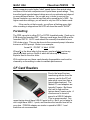
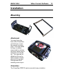
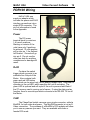
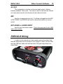
MoTeC USA ChaseCam For the PDR100 or PDR100-R USER MANUAL Revision 1.5 MoTeC USA ChaseCam Contents Introduction..............................................................3 ChaseCam PDR 100 ................................................5 Firmware Revisions............................................................................ 5 Hardware Version Identification ......................................................... 6 On-Board Batteries .......................................................................... 10 LED Status Lights ............................................................................ 10 Compact Flash Cards (CF) .............................................................. 11 Size Requirements ....................................................... 11 Speed Ratings.............................................................. 11 Formatting .................................................................... 12 CF Card Readers ............................................................................. 12 Installation..............................................................13 Mounting .......................................................................................... 13 PDR100 Wiring ................................................................................ 14 PDR100-R Wiring ............................................................................ 15 MoTeC Control Setup............................................16 ADL2, ADL3 or ACL Control Setup .................................................. 16 SDL Control Setup ........................................................................... 19 ADL Control Setup (VSM not compatible with ADL-1) ..................... 22 Video Convert Software ........................................25 Input Options.................................................................................... 25 Output Options ................................................................................. 26 Organizing Your Videos ................................................................... 27 Data Overlay...........................................................28 Adding the RS-232 Template....................................... 29 Appendices ............................................................33 Appendix A: ChaseCam Specifications............................................ 33 Appendix B: PDR100 Pin Out .......................................................... 34 Appendix C: PDR100-R Pin Out ...................................................... 36 Appendix D: Control String Setup .................................................... 37 MoTeC USA ChaseCam Copyright – Motec Systems USA – 2007, 2008 The information in this document is subject to change without notice. While every effort is taken to ensure correctness, no responsibility will be taken for the consequences of any inaccuracies or omissions in this manual. 5 March, 2009 MoTeC USA Introduction 3 Introduction Thank you for purchasing a MoTeC USA ChaseCam recorder. This system was developed to help customer’s integrate video into their data analysis. There are four steps in the Motec USA integration to the ChaseCam, each given an overview below. ChaseCam Control The first step is to control the ChaseCam unit by signaling it when to start recording and when to stop recording. By doing this, the recorded video matches the timing of the logged data. It also prevents the accidental mistake of the driver forgetting to turn on the recorder. Having Motec control the recording also keeps the video file sizes down to a minimum, as there is little use to recording warm-up or sitting on the grid waiting to go out on track. MoTeC USA Video Convert Software This software allows for the automation of moving video files from the CF memory card onto the computer, while at the same time renaming the file to a more descriptive name. If selected to, the software will convert the file type to a different format for multi camera playback in the “i2” Pro analysis software. While “i2” can play any type of video file, the compressed nature of files recorded on the ChaseCam can cause computer performance issues when playing multiple videos simultaneously. For example, playing two laps side-by-side. By converting the video file into an uncompressed format, it will allow the computer to play multiple videos at the same time without having to decode the compression. The conversion takes the “.mpg” file from ChaseCam and turns it into a “.avi” wrapped MJPEG format. MoTeC USA Introduction 4 “i2” Video Functionality With the Motec controlling the start point of the recording, once the video is transferred onto the computer then selecting that file will associate and sync it to the downloaded data. Now you can compare two laps side by side with Distance Based playback. There is an optional VSM or Video Sync Module available. This device encodes a unique signal onto one of the audio tracks and will allow “i2” to automatically find and sync the video file to the data file. Data Overlay For customers that want to see data real time on their video files directly, this option allows for any chosen channels of data to be displayed either as bar graphs or numeric values. It’s highly customizable to suit any need. This can also help to verify proper syncing has occurred. It requires an available RS-232 template not being used by telemetry. MoTeC USA ChaseCam PDR100 5 ChaseCam PDR 100 The ChaseCam PDR100 is an audio and video recorder, which writes digital files to a Compact Flash (CF) memory card. The unit accepts a single camera input, and can use either it’s own internal microphone, an external microphone or any stereo input. For more complete information about the PDR100, please refer to the ChaseCam PDR100 manual available online at http://www.chasecam.com/ then click on Support. Firmware Revisions Motec USA recommends that you use the latest version of firmware (software inside the ChaseCam) which is available online at http://www.chasecam.com/ under Support. New features and functions get added all the time and the software is free to download and install. To update the firmware, copy the “update.bin” file of which you downloaded, to the root directory of the CF memory card. Load the card into the ChaseCam. Hold down the MENU button and power up the unit. Hold the MENU button until you see the “UPDATER” text appear on the LCD screen, then release the MENU key. When it finishes updating then the unit will power off by itself. You will need to have version 01.02.06 or newer in order to use the control strategies listed in this manual. This version allows the momentary push switch to record while being held down, and stop recording when released. MoTeC USA ChaseCam PDR100 6 Hardware Version Identification Data Overlay There is a special MoTeC USA version, available only from MoTeC USA. This version allows for the real time Data Overlay function to perform. If you do not plan on doing live data overlay during the recording, then any ChaseCam unit will work. There are also different hardware versions of the PDR100. For data overlay, you must use one that was manufactured after March of 2007. Units prior to this can still have their recording on/off controlled by the Motec, they just can’t do the Data Overlay. VSM When using the Motec VSM, Video Sync Module, you will need either an external microphone or the newest revision 5 PDR100. This latest version has audio mixing capabilities, where the left audio track comes from the external audio input jack (used by the VSM) and the right audio track from the internal microphone. For older versions,an external mic adapter kit is available from MoTeC USA to work with the VSM. Rev 1-3 Rev 4 Rev 5 Power On/Off Motec controlled Motec controlled Recording Motec controlled Motec controlled Motec Controlled VSM Data Overlay Auto-On with ext mic with ext mic Yes No Yes* Yes* *only with a Motec enabled PDR PDR100 Revisions 1 thru 3 These were manufactured before March of 2007. If you currently own a prior unit and you want to do the data overlay, please contact MoTeC USA for an upgrade and current upgrade fee. MoTeC USA ChaseCam PDR100 PDR100 Revision 4 These were manufactured after March of 2007, known as Rev 4. They look identical to Rev 1-3 with a 4 prong green power plug. PDR100 Revision 5 These were manufactured after April of 2008 and can easily be identified by a 2 prong DC power terminal block. Another difference is the auto-on feature. To activate, slide the internal dip switch to the left. The switch is located inside on the left side of the CF card door. When active, the unit will turn on as soon as power is applied to the green connector. 7 MoTeC USA ChaseCam PDR100 8 Setup Menu Below are the recommended settings in Bold for the PDR100. Press the MENU keypad to enter setup. Press the X keypad to move back in the menu structure. Press the center <> button to select. CONTROLS RECORDING QUALITY Highest Higher Normal – recommended setting Subnormal Lower Lowest – not recommended VIDEO RESOLUTION Full Video – recommended setting 2/3 Horizontal – do not use One Quarter – use when more recording time is needed AUDIO INPUT CONTROLS AUDIO GAIN LEVEL Ext Line In Preset Ext Mic Close Preset Int Mic Close Preset Int Mic Wide Preset CUSTOM – Use this setting, with the left and right arrow keys, change the level meter displayed on the bottom to its minimum setting for both sliders. INT-EXC MIC LEVEL High – too much background noise with engine running. Low – recommended setting. SOURCE MIXING Turn Mixing On – use with VSM Turn Mixing Off – for non VSM installations LOOP RECORDING TURN LOOPING ON – this means it’s off TURN RECYCLE ON – this means it’s off SIZE LIMIT – should be set to 4096 MByte MoTeC USA ChaseCam PDR100 9 SETUP SET DATE AND TIME – Please verify this at the start of every race weekend. The ChaseCam much like your computer, can not tell what time zone you are located in. FILENAMES Number: Here you can set the first three characters of the file name. Most teams use the car number for identification purposes. Next Number: should say SAVED IN PDR not NEXT ON CARD. DISPLAY CONTRAST – moving the slider to change the contrast SERIAL NUMBER – Programmed at the factory. FEATURES ON SCREEN DISPLAYS – this feature is not applicable in the Motec version, as Motec has its own option for on screen data overlay. AUTO RECORD AT START – this feature is not applicable in the Motec version, as Motec controls the recording start and stop. AUTO SHUT DOWN – after selecting this feature, it should say AUTO SHUT DOWN IS OFF on the tope line of the display. RECORD SWITCH STYLE – after selecting this feature, it should say HOLDDOWN STYLE IN USE at the very top. The selection will show USE NORMAL REC SWITCH underneath. If the top says NORMAL RCORD IN USE then please arrow down and select USE HOLD-DOWN STYLE. Stop Delay should be set to 0 seconds. GFORCE RECORD TRIGGER – after selecting this feature, it should say GFORCE TRIGGER IS OFF on the tope line of the display. MoTeC USA ChaseCam PDR100 10 On-Board Batteries The PDR100 uses four AA sized batteries. The main power comes directly off the same 12 volt supply as the Motec dash, and therefore these batteries are only used as a backup. If a lose to main power occurs, the batteries allow the PDR100 to stop recording gracefully and finish writing the video file correctly. This prevents corrupt to the video file. It is recommended to use Lithium AA batteries instead of alkaline cells. For comparison, a lithium battery will last for 2 hours of recording, but an alkaline battery will last for only 3 minutes of recording. There is an optional SuperCap available. This capacitor takes the place of batteries, and provides enough power for up to 6 seconds after the initial charging time of one minute. This is enough time to shut down the recording without corrupting the video file. While you cannot turn the unit on with Supercaps, you will not have to worry about dead batteries. LED Status Lights The PDR100 has a dual color LED. Red LED Flashing: Recording but the battery is low. Flashing Slowly: Unit is armed for trigger starting. Green LED Steady: Unit is on and ready to record. Flashing Quickly: Playing back recorded file. Flashing Slowly: Not ready to record, view the LCD screen: “NO INPUT” for the video camera not present “NO CF CARD” if the CF card is absent The slow flashing can also signify low batteries or low disk space on the CF card. Red-Green LED Flashing Quickly: Recording video. MoTeC USA ChaseCam PDR100 11 Compact Flash Cards (CF) The PDR100 should accept most Type 1 or Type II CF card. This does not include CF style microdrives. Any size of CF card will work, but some limitations are imposed by the operating system and file types. Some computers have a 4GB limit to file size so there is little reason to get a larger CF card. Size Requirements Quality @ Full resolution screen size Highest 8.0 Mbits/Sec ~ 4GB per hour Higher 6.0 Mbits/Sec ~ 3GB per hour Normal 4.0 Mbits/Sec ~ 2GB per hour Subnormal 3.0 Mbits/Sec ~ 1.5GB per hour Lower 2.2 Mbits/Sec ~ 1.1GB per hour Lowest 1.5 Mbits/Sec ~ 0.75GB per hour Screen size @ Normal quality full = 4 Mbits/sec 2/3 = 2.56 Mbits/sec 1/4 = 1.37 Mbits/sec The LCD screen when on, will report an estimated recording time available for the existing settings. The recommended rate is normal quality at a full screen size setting. If you need to conserve space, try Subnormal quality. For a longer recording time, the screen size should be dropped to 1/4 screen size with Higher quality. Speed Ratings Video files are very large, and some memory cards can’t save that much information in real time. In order for the PDR100 to use higher video quality settings, the CF memory card must be capable of fast write times. Therefore the generic memory cards will not work well. The industry has some various ways of noting speed, but the most common is using a speed factor. 1X is 150Kbits/s 24X is 3.6Mbits/s 40X is 6Mbits/s 60X is 9Mbits/s MoTeC USA ChaseCam PDR100 12 Many companies quote higher “ideal” speed factors than actual rates and some of the best companies won’t quote these speed ratings. They know that such reported speed ratings are only an estimate and depend on many different factors. As you can see, in order to use just the Normal resolution you need a card that with a speed factor of 40X. For higher resolution settings, you will want to only use 60X or faster cards. If the card is not fast enough, you will see a flashing green light after recording is stopped and the LCD will show the words “SLOW”. Formatting The PDR can write to either FAT or FAT32 formatted cards. Cards up to 4GB should be formatted FAT. Memory cards larger than 4GB must be formatted FAT32. All CF cards should be manually formatted to force 32K cluster sizes. This can be done via the command prompt otherwise known as a DOS prompt. Below is an example: format E: /FS:FAT /V:label /A:32K Where E: is the drive letter to the memory card and label can be any identifying label such as Car24 of which will show up in Windows Explorer next to the drive letter. With continuous use, these cards develop fragmentation and must be cleaned by re-formatting in order to maintain performance. CF Card Readers Due to the large file sizes, transferring movies from the memory card to the PC will take much more time than a typical data download. The fastest CF card adapters are typically Firewire. But these are hard to find and few laptops have Firewire ports. A close second in terms of speed is a USB 2.0 adapter. This is recommended. Any recent laptop should have USB 2.0 ports built in. But if you’re laptop is old it might have USB 1.1 ports, and therefore the transfer time will be very slow. PCMCIA adapter are similar in speed to USB 1.1 and therefore not recommended. MoTeC USA Video Convert Software Installation Mounting Attachment You may Velcro the back of the ChaseCam unit to the car, or use the optional mounting cage. This cage allows for easy to remove access and is a cleaner and more secure way to mount the unit into the car. The cage can be affixed into the car by either screws or heavy duty hook & loop tape. See Appendix B for mounting screw layout. Orientation The ChaseCam PDR100 can be mounted in any orientation. 13 MoTeC USA Video Convert Software 14 PDR100 Wiring MoTeC USA can supply an adapter which includes the power and RJ45 interface connections into a single DTM connector. The pin out information is found in the Appendix. Power The DC power terminal block on revisions 1-4 have 4 positions. Starting on revision 5 the units have only 2 positions. As pictured, 12 volts positive will go into pin 1, the farthest left location. Ground will go into pin 2. Do not use the other two slots for anything unauthorized or damage will result. RJ45 Contains the switch trigger which connects to an available Aux Output of the Motec. Also contains both green and red LED status lights which can be wired only into an analog voltage input. Required for operation is the red LED, which specifies the unit is recording. The green LED is optional and will report if the unit is powered and flash if the CF memory card is running out of space. If using the data overlay function, there is a serial input which connects to the RS-232 TX line of the Motec. CAM The ChaseCam lipstick cameras use a single connector, called a MiniDIN, for both video and power. This MiniDIN connector is not an SVideo connection. The purchase of a MiniDIN to RCA adapter will allow you to use any camera you want. They are available with male or female RCA ends. MoTeC USA Video Convert Software 15 AV OUT This connection is used as a video and audio output, utilizing industry standard 3.5mm jack. This can be used to help aim the camera or to play back from the unit directly onto an external monitor. MIC Input for un-powered mics only. If nothing is plugged into the MIC or EXT AUDIO, the PDR100 will use its internal microphone to record sound EXT AUDIO or AUDIO INPUT Input for line level stereo audio. This is the input jack for the VSM, video sync module. PDR100-R Wiring In order for the internal mic to be used for sound, the Audio Out must be wired back into the Audio In Left or Right, or both. For the VSM, wire the VSM into Audio Left and the Audio Out gets looped back into Audio Right. MoTeC USA Video Convert Software 16 MoTeC Control Setup This section describes how the Motec should be setup to start and stop recording. Choose the appropriate one for your hardware. For all setups, the ChaseCam PDR100 must have the switch feature set to HOLDDOWN STYLE IN USE. ADL2, ADL3 or ACL Control Setup STEP 1: Decide when you want the recording to start and stop. If you have a VSM then you can choose to record separately from the logging. If you are not using the VSM, then you will want the recording to start at the exact same time as the logging. When done this way, the video and data will by synced by start point. The ChaseCam takes about 0.35 seconds to start recording once triggered. Therefore the output should trigger 0.35 seconds before the Motec starts to log data. Verify what your logging Start/Stop Conditions are set to. Below is an example of what the logging conditions might be, found under the Logging Setup window. MoTeC USA Video Convert Software 17 STEP 2: Create a new user condition that is similar to your logging start & stop conditions, only the time periods are 0.35 seconds less. For the output channel, rename any of the “Condition X” channels to “ChaseCam Recording”. With the VSM, it’s not required to start the recording at the same time as the logging. Therefore you can generate different start and stop conditions for the ChaseCam PDR100. This might be useful if you want to log the engine warm up time, but only record video while the car is moving. STEP 3: Using any of the available Auxiliary Outputs, setup the control channel as follows. This output should be connected to the switch control input on the ChaseCam. Remember on an ADL with 30 I/O only the first four Aux Outputs are available. To use Aux Outputs 5 through 8 the dash must have the 50 I/O option. MoTeC USA Video Convert Software 18 Optional STEP 4: The red LED indicates the unit is recording, while the green LED indicates the unit has power. Both status wires can be connected to any available AV or analog voltage input. For the channel, select a “General Purpose On/Off” channel and rename them to “ChaseCam Red LED” and “ChaseCam Green LED”. Calibrate as follows: Optional STEP 5: If your ChaseCam has a 4 prong green power plug, then it is not possible to automatically turn on by itself. So the output needs to be triggered by the Motec to turn the ChaseCam unit on. See the picture below for the extra lines required. MoTeC USA Video Convert Software 19 SDL Control Setup STEP 1: Decide when you want the recording to start and stop. If you have a VSM then you can choose to record separately from the logging. If you are not using the VSM, then you will want the recording to start at the exact same time as the logging. When done this way, the video and data will by synced by start point. The ChaseCam takes about 0.35 seconds to start recording once triggered. Therefore the output should trigger 0.35 seconds before the Motec starts to log data. Verify what your logging Start/Stop Conditions are set to. Below is an example of what the logging conditions might be, found under the Logging Setup window. STEP 2: Create a new user condition that is similar to your logging start & stop conditions, only the time periods are 0.35 seconds less. For the output channel, rename any of the “Condition X” channels to “ChaseCam Recording”. MoTeC USA Video Convert Software 20 With the VSM, it’s not required to start the recording at the same time as the logging. Therefore you can generate different start and stop conditions for the ChaseCam PDR100. This might be useful if you want to log the engine warm up time, but only record video while the car is moving. STEP 3: Using any of the available Auxiliary Outputs, setup the control channel as follows. This output should be connected to the switch control input on the ChaseCam. MoTeC USA Video Convert Software 21 Optional STEP 4: The red LED indicates the unit is recording, while the green LED indicates the unit has power. Both status wires can be connected to any available AV or analog voltage input. For the channel, select a “General Purpose On/Off” channel and rename them to “ChaseCam Red LED” and “ChaseCam Green LED”. Calibrate as follows: Optional STEP 5: If your ChaseCam has a 4 prong green power plug, then it is not possible to automatically turn on by itself. So the output needs to be triggered by the Motec to turn the ChaseCam unit on. See the picture below for the extra lines required. MoTeC USA Video Convert Software 22 ADL Control Setup (VSM not compatible with ADL-1) STEP 1: Because the ADL does not support the VSM, you will want the recording to start at the exact same time as the logging. When done this way, the video and data will by synced by start point. The ChaseCam takes about 0.35 seconds to start recording once triggered. Therefore the output should trigger 0.35 seconds before the Motec starts to log data. First verify what your logging Start/Stop Conditions are set to. Below is an example of what the logging conditions might be, found under the Logging Setup window. MoTeC USA Video Convert Software 23 STEP 2: Create a new user condition that is similar to your logging start & stop conditions, only the time periods are 0.35 seconds less. The stop condition will go on the third line with the additional ChaseCam Recording True condition. For the output channel, rename any of the “Condition X” channels to “ChaseCam Recording”. STEP 3: Using any of the available Auxiliary Outputs, setup the control channel as follows. This output should be connected to the switch control input on the ChaseCam. Remember on an ADL with 30 I/O only the first four Aux Outputs are available. To use Aux Outputs 5 through 8 the dash must have the 50 I/O option. MoTeC USA Video Convert Software 24 Optional STEP 4: The red LED indicates the unit is recording, while the green LED indicates the unit has power. Both status wires can be connected to any available AV, analog voltage input. For the channel, select a “General Purpose On/Off” channel and rename them to “ChaseCam Red LED” and “ChaseCam Green LED”. Calibrate as follows: Optional STEP 5: If your ChaseCam has a 4 prong green power plug, then it is not possible to automatically turn on by itself. So the output needs to be triggered by the Motec to turn the ChaseCam unit on. See the picture below for the extra lines required. MoTeC USA Video Convert Software 25 Video Convert Software This program allows you to easily move files from the CF memory card to your computer, rename them and clear them off the CF card. The software can also convert video files from “.mpg” to “.avi”. Input Options With Manual Conversion selected, you can convert a single file from “.mpg” to a motion jpeg “.avi”. The directory location will be remembered each time you choose a new path. With Automatic Conversion selected, the software will scan the drive selected (such as your CF card) looking for video files to copy and/or convert into the output path on your computer. It will only search the root directory and all folders under the DCIM directory (this is the default directory that ChaseCam puts the video files). MoTeC USA Video Convert Software 26 Output Options Under the Output Path, you can select what folder to store your video files on the computer. There is also an option to delete the original files when finished. This is handy for CF cards that will be put back into the ChaseCam for further recordings. When converting files, there will be pull down menu boxes to adjust the settings. For full screen video select the VGA setting. The as-recorded bit rate will give the best quality but really larger files (about 6 times larger than mpg). Try setting the bit rate to high for good quality and much smaller files (only 3 times larger). For use with “i2” only, choose the sVGA setting and a bit rate of high. The last section will allow you to rename the file based on Driver, Track and Session. If the Automatic Conversion is selected, the file name will contain the last 3 digits of the original files as a way to separate multiple video files on the CF memory card. MoTeC USA Video Convert Software 27 Organizing Your Videos There are two ways to organize your videos. If you plan to use the video for other purposes, besides “i2” then choose the second option. If you are only going to be viewing the videos in “i2” then choose the first option. Option 1) Convert MPG files to AVI and only keep AVI files. The advantage of this is that you have less files to keep track of. The disadvantage is it takes up more space. Option 2) Convert MPG files to AVI and keep both formats. This will allow you to record higher quality files, keep those for future use, and yet have a smaller video file for use in “i2”. The organization should be done in a systematic way. Videos should be stored on an external hard drive as they will quickly fill up a laptop drive. For your Motec Data: C:\ Motec \ Logged Data \ track 1 C:\ Motec \ Logged Data \ track 2 C:\ Motec \ Logged Data \ track 3 C:\ Motec \ Logged Data \ ... OR C:\ Motec \ Logged Data \ year \ track 1 C:\ Motec \ Logged Data \ year \ track 2 C:\ Motec \ Logged Data \ year \ track 3 C:\ Motec \ Logged Data \ year \ ... For your Motec Videos: E:\ Motec \ Videos \ track 1 E:\ Motec \ Videos \ track 2 E:\ Motec \ Videos \ track 3 E:\ Motec \ Videos \ ... AND (optionally) E:\ Motec \ Original Videos \ track 1 E:\ Motec \ Original Videos \ track 2 E:\ Motec \ Original Videos \ track 3 E:\ Motec \ Original Videos \ ... MoTeC USA Data Overlay 28 Data Overlay The ChaseCam PDR100 can be programmed to provide some pixel overlays real time on top of the incoming video as it gets recorded. There are two pixel areas that can be programmed. 1. Vertical Section: Consists of 4 pixels wide and either 48 pixels tall for NTSC or 60 pixels tall for PAL standards. Pixels are square. It can be displayed on the left or right side. 2. Horizontal Section: Consists of 8 pixels tall and 128 pixels wide. They are rectangular pixels where the height is half the width. This area can be used to display a maximum of 21 characters across. It can be displayed on the top or bottom. Both sections are set just inside of “TV Safe” zone. When a normal television plays any video signal, it will crop off the actual picture. When the same video signal is played on a computer or newer television, the entire picture is shown. There is also an option to have the background of the data overlay areas to display in black or be transparent as shown below. The layout can be customized to display many different things. See Appendix E for a complete list of setup information. For ease of use, MoTeC USA has created a number of predefined layouts each detailed in this section. To create your own, it might be easier to start with one of these 3 predefined layouts and modify for your use. MoTeC USA Data Overlay 29 The data overlay requires channels to be sent out via RS-232 serial. This means that the serial port can not be used for receiving GPS information nor can it concurrently send telemetry out. To use GPS with the Data Overlay, consider the purchase of a serial to CAN adapter, (STC) from your Motec dealer. Adding the RS-232 Template Please contact MoTeC USA for help in creating the ChaseCam template files. The templates will require 2D tables to be setup for all parameters in order to scale them from 0 to 255 or -127 to 127. Additionally, constants must be setup to control the type and location of each parameter. Start by renaming the channels below and adding the constants as you desire. Three examples are provided. Renaming Channels Depending on which template you choose to use, there will exist GP Constant channels that should be renamed to correspond to their appropriate function. Below is a list of the different GP Constant channels and what they should be renamed to. After choosing your RS232 template, rename any of the following channels which might exist in your config file. To do this, under the “Tools” pull down menu, should select “Edit Channels”. Then find and rename any of the following that you see: GP Constant 1 ChaseCam Setup Brakes GP Constant 2 ChaseCam Setup TP GP Constant 3 ChaseCam Setup Speed GP Constant 4 ChaseCam Setup Lap # GP Constant 5 ChaseCam Setup Steer Ticks GP Constant 6 ChaseCam Setup Steering GP Constant 7 ChaseCam Setup TP Ticks GP Constant 8 ChaseCam Setup Time GP Constant 13 ChaseCam Steer Ticks GP Constant 16 ChaseCam TP Ticks Constants For each template, there are a number of “Constants” that must be defined under the Inputs pull down menu. These constants are ChaseCam setup values that define the location and type of data to be overlaid onto the video. MoTeC USA Data Overlay 30 ChaseCam 1 Ground Speed (mph) Tick Marks Steering Wheel Angle Lap Number Brake Pressure Front / Throttle Pos Constants Setup Information MoTeC USA Data Overlay 31 ChaseCam 2 Ground Speed (mph) Tick Marks Steering Wheel Angle Lap Number Brake Pressure Front / Tick Marks / Throttle Pos Constants Setup Information MoTeC USA Data Overlay ChaseCam 3 Lap Number Constants Setup Information Running Lap Time 32 MoTeC Appendices Appendices Appendix A: ChaseCam Specifications PDR100 & PDR100-R Physical Case Size: 4.5”(w) x 3.5”(d) x 1.75”(h) (excluding connectors) Weight: 454 grams without batteries Batteries: Replaceable AA (x4) Power Supply Operating Voltage: 9 to 18 Volts DC Operating Current: 0.500 Amps Typical with one camera Operating Temperature Ambient Temperature Range: 0°F to 110°F / -17°C to 43°C Mounting Cage Layout Inner holes: 1.25” apart, 1.5” from center, flat head screws only Outer holes: 1.25” apart and 5.45 from center to center 33 MoTeC Appendices 34 Appendix B: PDR100 Pin Out DTM8 Connector Adapter DTM8 Pin # 1 2 3 4 5 6 7 8 Motec Connection Ground Power, 12 volt RS-232 TX Aux Output AV input only Aux Output for VSM n/a AV input only RJ45 Pin # n/c n/c 7 5 6 n/c n/c 3 ChaseCam Function see Power Connector see Power Connector serial RX Remote Switch Red LED, recording status n/a n/a Green LED, power status Notes: Motec RS-232 TX serial communication uses the following pins: • ADL, ADL2, ADL3 pin 67 *not available • ACL pin 33 or 22 *The Data Overlay option can not be used if the serial port is a) receiving channels from other devices such as a GPS or ECU b) used for telemetry c) in a Dodge Viper Comp Coupe or SRT-4 where this pin is used to communicate with the factory ECU, except for ADL-1 Harness Side To ChaseCam MoTeC Appendices Power Connector, 2 pin Terminal Block Pin 1 2 Function Power, 12 volt Ground Motec Connection ADL pin 8 ADL pin 7 Power Connector, 4 pin Terminal Block Pin 1 2 3 4 Function Power, 12 volt Ground 12 volt output, 300mA max Ground output, 300mA max MiniDin Camera, 4 pin Pin AUX +12VDC COM VID Function n/a Video Camera Power, 12v Video Camera Ground Video Camera Input Motec Connection ADL pin 8 ADL pin 7 n/a n/a 35 MoTeC Appendices 36 Appendix C: PDR100-R Pin Out AUX AUDIO, mating connector is AS608-35SN Pin Function 1 Audio Left Input 2 Audio Right Input 3 Audio Ground 4 Mic Left Input 5 Mic Right Input 6 Mic Output Note: For the internal MIC to operate, you need to tie the MIC OUTPUT into either both or just one of the audio inputs. VIDEO + INTERFACE, mating connector is AS610-35SN Pin 1 2 3 4 5 6 7 8 9 10 11 12 13 Function Remote Switch Remote Ground Green LED Red LED RS-232 TX RS-232 RX Remote Power Video Camera Ground Video Camera Input Video Camera Power, 12v Video Signal Output Ground Power, 12 volt Motec Connection Aux Output n/a AV input only AV input only n/a RS-232 TX n/a Wired to Camera Wired to Camera Wired to Camera ext. aiming screen ADL pin 7 ADL pin 8 Notes: Motec RS-232 TX serial communication uses the following pins: • ADL, ADL2, ADL3 pin 67 *not available • ACL pin 33 or 22 *The Data Overlay option can not be used if the serial port is a) receiving channels from other devices such as a GPS or ECU b) used for telemetry c) in a Dodge Viper Comp Coupe or SRT-4 where this pin is used to communicate with the factory ECU, except for ADL-1 MoTeC Appendices 37 Appendix D: Control String Setup The RS-232 serial stream consists of 2 lines. The first line is made up of setup information, such as the type of display either a bar graph, tick marks or text. The second line contains the channel values to be displayed. Definition of Setup Line: X,t,l,w,t,l,w,t,l,w... Begins with a hexadecimal number, “X” of value 200 + flag settings. This value is set as the compound line identifier. Defined so far: + 1 : black background instead of transparent background + 2 : vertical area is placed on right side instead of left side + 4 : horizontal area is placed on bottom instead of top Followed by any number of data item records. Each record will be of the following form, each preceded by commas: ,t,l,w t : specifies Type and Anchoring l : specifies Location w : specifies Width Values for t, Type: 10 = text in horizontal area 11 = Horizontal bar anchored at left 12 = Horizontal bar anchored at center 13 = Horizontal bar anchored at right 14 = Horizontal spot anchored at left 15 = Horizontal spot anchored at center 16 = Horizontal spot anchored at right 17 = Horizontal tick anchored at left with a tick there 18 = Horizontal tick anchored at center with a tick there 19 = Horizontal tick anchored at right with a tick there 20 = Vertical bar anchored at bottom 21 = Vertical bar anchored at center 22 = Vertical bar anchored at top 23 = Vertical spot anchored at bottom 24 = Vertical spot anchored at center 25 = Vertical spot anchored at top 26 = Vertical tick anchored at bottom with a tick there 27 = Vertical tick anchored at center with a tick there 28 = Vertical tick anchored at top with a tick there 29 = time in mm:ss.dd if width is 8, ss.dd if width is 5 30 = time in hh:mm:ss if width is 8, mm:ss if width is 5 If time width is 9, a leading space is put in front of 8 characters. If time width is 6 or 7, one or two leading spaces are put in front The width in characters should count the colons and decimal point. MoTeC Appendices 38 Values for L, Start Location: Vertical Area: 1-4 to specify pixels from the left. Horizontal Area: 1-8 to specify row pixels from the top. 11-31 to specify character position for text from the left. Values for W, Width: Vertical Area: 1-4 for width in pixels. Horizontal Area: 1-8 for row height in pixels. 1-9 for number of characters in text field. NOTE: Horizontal bars will automatically fill into the single longest open space on the line, not on both sides of text fields. If there are more than one open space of equal lengths, the left-most would be used. Definition of Data Line: Starts with 0, then contains N data items corresponding to the N records of most recent setup line sent. 0,xxxx,xxxx,xxxx,xxxx... xxxx can be comma separated number values or text strings with no comma allowed in text. This will be followed by a line terminator CR, or LF, or CR-LF. Number values must range from 0 through 255 in the case of bottom, top, left, or right anchoring or -128 through 127 in the case of center anchoring. Other decimal values may be transmitted but will be limited to the endof-scale values by the display routines. For ticks types, the data value represents the interval between ticks starting from the anchor position tick. MoTeC Notes 39 Example 1: Below is a break down of what each number represents in the setup values as used in this example. ChaseCam Setup Brakes channel has a value of 2012. “20” = a vertical bar anchored at bottom st “1” = start at the 1 pixel location from the left “2” = number of pixels wide ChaseCam Setup TP channel has a setting of 2032 where: rd “3” = start at the 3 pixel from the left “2” = width in pixels ChaseCam Setup Speed channel has a value of 10113: “10” = text in horizontal area st “11” = start number at 1 character location from the left “3” = number is 3 characters wide ChaseCam Lap # channel has a setting of 10293 where: “10” = text in horizontal area th “29” = start number at 19 character location from the left “3” = number is 3 characters wide ChaseCam Setup Steer Ticks setting of 1812 comprises of: “18” = Horizontal tick marks st “3” = starts at 1 pixel “2” = has a height of 2 pixels ChaseCam Steering setting of 1233 comprises of: “12” = Horizontal bar graph rd “3” = starts at 3 pixel down out of 8 possible “3” = 3 pixels in width ChaseCam Steer Ticks setting of 30 represents a tick mark every 30 units. The bar graph values range from “0 to 255” or “-128 to 127” for center anchoring bars. With a value of 30 that will correspond to 8 ticks over the range, calculated from 255/30 = 8. MoTeC Notes 40